circuit breaker application guidemerlin gerin
TRANSCRIPT

Merlin GerinCircuit breakerapplication guide
M M M M
M
M
M
M
M M M M M
MERLIN GERIN
multi 9C60NC63400Va6000
24234 2 4
10kA IEC 947.2
O - OFFO - OFFO - OFFO - OFF
6 8
1 3 5 7
MERLIN GERIN
multi 9C60NC25230Va6000
24178
O - OFF
10 kA IEC 947.2
MERLIN GERIN
multi 9C60NC63400Va6000
24234 2 4
10kA IEC 947.2
O - OFFO - OFFO - OFFO - OFF
6 8
1 3 5 7
1.5
2
3
4 5
6
8
10xIr
Im
.63
.7
.8
.85 .9
.95
.98
1xIn
IrSTR 22 SE90
105%Ir
alarm
ImIr
I n = 2 5 0 A
250N
P93083
OFF
MERLIN GERINcompactNS250 NUi 750V. Uimp 8kV.
220/240380/415440500660/690250
853635308
50
cat A
IEC947-2UTE VDE BS CEI UNE NEMA
Ue(V)
Icu(kA)
Ics=100% Icu
160/250Apushto
trip
pushto
trip
250N
P93083
1.5
2
3
4 5
6
8
10xIr
Im
.63
.7
.8
.85 .9
.95
.98
1xIn
IrSTR 22 SE90
105%Ir
alarm
ImIr
I n = 2 5 0 A
OFF
MERLIN GERINcompactNS250 NUi 750V. Uimp 8kV.
220/240380/415440500660/690250
85363530
850
cat A
IEC947-2UTE VDE BS CEI UNE NEMA
Ue(V)
Icu(kA)
Ics=100% Icu
160/250Apushto
trip
pushto
trip
MERLIN GERIN
multi 9ID'clicC32
40 mA
∆n 0,030A230Va
20564
20564
ID'clicbi 40 A
BS EN 61009
a3000
3
N 1L1 3L2
I . ON
MERLIN GERINmulti 9NG 125L
In = 125A
220/240V380/415V440V500V
Ue(V)5025156
IEC 947.218806
Icu(kA)
1.5
2
3
4 5
6
8
10xIr
Im
.63
.7
.8
.85 .9
.95
.98
1xIn
IrSTR 22 SE90
105%Ir
alarm
ImIr
I n = 2 5 0 A
250N
P93083
OFF
MERLIN GERINcompactNS250 NUi 750V. Uimp 8kV.
220/240380/415440500660/690250
853635308
50
cat A
IEC947-2UTE VDE BS CEI UNE NEMA
Ue(V)
Icu(kA)
Ics=100% Icu
160/250Apushto
trip
pushto
trip
Ic
µP
>Ir
>Im
test faultSTR 53 UE 60 75 90 105 %Ir
IImIrIo
tr tm(s)
x Inx Irx Iox In
on I2t off(s) at 1.5 Ir
test
R
tr
tm
ImIr I
MERLIN GERINcompact
NS400 HUi 750V. Uimp 8kV.
Ue(V)
220/240
380/415
440
500/525
660/690
1007065
40
35
IEC 947-2UTE VDE BS CEIUNE NEMA
Icu(kA)
cat B
Ics = 100% IcuIcw 6kA / 0,25s
In = 400A
.8
1
.63
.5
.9 .93.95
.98
.88
.85
.8 1
4 56
8
3
2
1.5 10
4 68
10
3
2
1.5 12
.3 .3.2
.1
.2
.1
0 0
120 24060
30
15 240
.9 .93.95
.98
.88
.85
.8 1
pushto
trip
pushto
trip400
250N
P93083
1.5
2
3
4 5
6
8
10xIr
Im
.63
.7
.8
.85 .9
.95
.98
1xIn
IrSTR 22 SE90
105%Ir
alarm
ImIr
I n = 2 5 0 A
OFF
MERLIN GERINcompactNS250 NUi 750V. Uimp 8kV.
220/240380/415440500660/690250
853635308
50
cat A
IEC947-2UTE VDE BS CEI UNE NEMA
Ue(V)
Icu(kA)
Ics=100% Icu
160/250Apushto
trip
pushto
trip
Reset
resetApIgI ∆n
IsdI i
Ir
Micrologic 70
Ics = 100% Icu
220/440525690
10010085
Icw 85kA/1s
NX 32 H 2
cat.B
IEC 947-2
UTE VDE BS CEI UNE AS NEMAEN 60947-2
50/60Hz
Ue Icu(V) (kA)
0 1 2 5 3
push OFF push ON
O OFF discharged

1
Contents
Description
Circuit breakers and system design
The requirements for electrical power distribution
Safety and availability of energy
Structure of LV electrical power distribution
Functions and technologies of protection devices
Standard BS EN 60947-2
Current limitation
Cascading
Discrimination
Earth leakage protection discrimination
Range of circuit breakers
Discrimination rules
LV discrimination study
Enhanced discrimination and cascading
Supplementary requirements
Transformer information
Cable fault reduction
400Hz operation
DC information
Residual current device selection
Circuit breaker markings
LV switch disconnectors
Technical data
Cascading tables
Discrimination tables
Type 2 co-ordinationtables for motor protection
Co-ordination with Telemecanique busbar
Section
1
2
3
Page
3
55
77

2
1000 kVA
1000 A
M M
100 A400 A
100 A 160 A
75 kW
16 A
20 kV/400 V1000 kVA
1600 A
1000 kVA
19 kA
45 kA
60 kA
23 kA70 kA
mainswitchboard
building utilities
lighting, heating, etc.
distributionboard
sub-distributionswitchboard
power distributionswitchboard -industrial/commercial
non-priorityfeeders
priority feeders
distribution
distributionenclosure
distributionworkshop 1

3
Section 1System requirements
Circuit breakers and system design
Safety and availability of energy
Structure of LV electrical power distribution
Functions and technologies of protection devices
Standard BS EN 60947-2
Current limitation
Cascading
Discrimination
Discrimination rules
Earth leakage protection discrimination
Coordination of protection devices
Range of circuit breakers
LV discrimination study
Enhanced discrimination and cascading
Page
5
6
7
10
15
19
21
25
26
28
30
43
46

4
Glossary
EDW:
SCPD:
IEC:
BS:
CT:
CU:
MSB:
BBT:
MV:
Isc:
Isc(D1):
Usc:
MCCB:
BC:
Icu(*):
IcuD1(*)
Ue:
Ui:
Uimp:
In:
Ith:
Ithe:
Iu:
Icm:
Icu:
Ics:
Icw:
Ir:
1.05 x Ir:
1.30 x Ir:
Ii:
Isd:
ElectroDynamic Withstand
Short circuit protection device
International Electrotechnical Commission
British Standard
Current transformers
control Unit
Main Switchboard
Busbar Trunking
Medium Voltage (1kV to 36kV)
Short-circuit current
Short-circuit current at the point D1 is installed
Short-circuit voltage
Moulded case circuit-breaker
Breaking Capacity
Ultimate Breaking Capacity
Ultimate Breaking Capacity of D1
Rated operational voltage
Rated insulation voltage
Rated impulse withstand voltage
Rated operational current
Conventional free air thermal current
Conventional enclosed thermal current
Rated uninterrupted current
Rated short-circuit making capacity
Rated ultimate short-circuit breaking capacity
Rated service breaking capacity
Rated short time withstand current
Adjustable overload setting current
Conventional non-tripping current
Conventional tripping current
Instantaneous tripping setting current
Short time tripping setting current

5
The design of LV installations leads to basic protection devicesbeing fitted for three types of faults:c overloadsc short-circuitsc insulation faults.
Operation of these protection devices must allow for:c the statutory aspects, particularly relating to safety of people,c technical and economic requirements.
The chosen switchgear must:c withstand and eliminate faults at optimised cost with respect to the necessaryperformance,c limit the effect of a fault to the smallest part possible of the installation in order toensure continuity of supply.
Achievement of these objectives requires coordination of protection deviceperformance, necessary for:c managing safety and increasing durability of the installation by limiting stresses,c managing availability by eliminating the fault by means of the circuit-breakerimmediately upstream
The circuit-breaker coordination means are:c cascadingc discrimination.
If the insulation fault is specifically dealt with by earth fault protection devices,discrimination of the residual current devices (RCDs) must also be guaranteed.
Safety and availability of energyare the operator s primerequirements.Coordination of protection devicesensures these needs are met atoptimised cost.
Safety and availability of energy
The requirements of electrical power distribution

6
The various levels of an LV electrical installationEach of the three levels of the installation has specific availability and safety needs.
Structure of LV electrical powerdistribution
The requirements of electrical power distribution
Simplified diagram of a standard installation covering most of the cases observed in practice.
1000 kVA
1000 A
M M
100 A400 A
100 A 160 A
75 kW
16 A
20 kV/400 V1000 kVA
1600 A
1000 kVA
19 kA
45 kA
60 kA
23 kA70 kA
mainswitchboard
building utilities
lighting, heating, etc.
distributionboard
sub-distributionswitchboard
power distributionswitchboard -industrial/commercial
non-priorityfeeders
priority feeders
distribution
distributionenclosure
distributionworkshop 1
Level A
Level B
Level C

7
Circuit-breaker functionsThis connection device is able to close and break a circuit regardless of current up toits breaking capacity.The functions to be performed are:c close the circuit,c conduct current,c open the circuit and break the current,c guarantee isolation.The requirements concerning installation, cost optimisation, management ofavailability and safety generate technological choices concerning the circuit-breaker.
Level A: the Main Switchboard (MSB)This unit is the key to the entire electrical power distribution: availability of supply isessential in this part of the installation.
c Short-circuit currents are high due to:v the proximity of the LV sources,v amply sized busbars for conveying high currents.
ccccc This is the area of the power circuit-breakers
Functions and technologies of theprotection devices
Own current compensationdiagram
Protection devices and theircoordination must be suited tothe specific features of theinstallation.c At the main switchboard, the needfor energy availability is greatest,c At the sub-distributionswitchboards, limitation of stressesin event of a fault is important,c At final distribution, user safety isessential.
1/3
2/3
i
i
A
i
ccccc Main data of these circuit-breakers:v of industrial type, meeting standard BSEN 60947-2,v with a high breaking capacity lcu from 40 to 150 kA,v with a nominal rating of 1000 to more than 5000 A,v category B:- with a high lcw from 40 kA to 100 kA — 1 s- with a high electrodynamic withstand (EDW),v with a stored energy operating mechanism allowing source coupling.Continuity of supply is ensured by total discrimination:v upstream with the protection fuses of the HV/LV transformer (*),v downstream with all the feeders (time discrimination).
(*) The value of HV/LV discrimination lies above all in the fact that resumption of operation hasfewer constraints in LV (accessibility, padlocking). This offers considerable advantages forcontinuity of supply.
These circuit-breakers are designed for high currentelectrical distribution:v they are normally installed in the MSBs to protecthigh current incomers and feeders;v they must remain closed in event of short-circuits soas to let the downstream circuit-breaker eliminate thefaults. Their operation is normally time-delayed.ElectroDynamic Withstand (EDW) and high thermalwithstand characterised by a short time withstandcurrent lcw are essential.EDW is designed to be as great as possible by an owncurrent compensation effect.

8
Level B: the subdistribution boardsThese boards belong to the intermediate part of the installation:c distribution is via conductors (BBT or cables) with optimised sizing,c sources are still relatively close: short-circuit currents can reach 100 kA,c the need for continuity of supply is still very great.Protection devices must consequently limit stresses and be perfectly coordinatedwith upstream and downstream LV distribution.
This is the area of the moulded case circuit-breakersThese circuit-breakers must open and break the current as quickly as possible. Themain need is to avoid as far as possible stresses at cable and connection level andeven at load level. For this purpose, repulsion at contact level must be encouragedin order to eliminate the fault even as the current is rising.
Fm
i
i
Fm The possible diagramsare:c with a single repulsionloop,c with double repulsionc with an extractor, amagnetic core pushing orpulling the movingcontact.
Example of a repulsion diagram Fm = magnetic force
The repulsion effects can be enhanced by implementation of magnetic circuits:c with effects proportional to the current square (U-shaped attracting or expulsioncircuit),c with effects proportional to the current slope (di/dt) and thus particularly effectivefor high currents (lsc).
Main data of the moulded case circuit-breakers:c of industrial type, meeting standard BSEN 60947-2,c with a high breaking capacity (36 to 150 kA),c with a nominal rating from 100 A to 1600 A,c category B for high rating circuit-breakers (> 630 A),c category A for lower rating circuit-breakers (< 630 A),c with fast closing and opening and with three operating positions (ON/OFF/Tripped).
Continuity of supply is ensured by discrimination:c partial, possibly, to supply non-priority feeders,c total for downstream distribution requiring high energy availability.
The requirements of electrical power distribution

9
Level C: Final distributionThe protection devices are placed directly upstream of the loads: discrimination withthe higher level protection devices must be provided.A weak short-circuit current (a few kA) characterises this level.
c This is the area of the Miniature Circuit-breaker
i
i
Fmi
These circuit-breakers are designed to protect finalloads. The purpose is to limit stresses on cables,connections and loads.The technologies for the miniature circuit-breakers,mainly used at this installation level, prevent suchstresses from occurring.In miniature circuit-breakers, limitation partly dependson the magnetic actuator. Once the mechanism hasbeen released, it will strike the moving contact makingit move at a high speed very early on. Arc voltage thusdevelops very quickly at a very early stage. For smallrating circuit-breakers, specific pole impedancecontributes to limitation.The miniature circuit-breaker is ideal for domestic useand for the protection of auxiliaries; it then conforms tostandard BSEN 60898.On the other hand, if it is designed for industrial use, itmust meet standard BSEN 60947-2.
Main data of these circuit-breakers:ccccc a breaking capacity to match needs (i.e. Below 10 kA on average),ccccc a nominal rating of 1.5 to 125 A according to the loads to be supplied,ccccc normally intended for domestic applications: conform to standard BSEN 60898.
The protection devices installed must provide:ccccc current limitation,ccccc operating convenience,ccccc absolute safety,as these devices are handled by non-specialist users.

10
-Changes in dependability needs and technologies have led to a marked increase instandard requirements for industrial circuit-breakers. Conformity with standard IEC947-2, renamed IEC 60947-2 in 1997 and BSEN60 947-2 can be considered as anall-risk insurance for use of circuit-breakers. This standard has been approved byall countries.
The principlesStandard BSEN 60947-2 is part of a series of standards defining the specificationsfor LV electrical switchgear:c the general rules BSEN 60947-1, that group the definitions, specifications andtests common to all LV industrial switchgear,c the product standards BSEN 60947-2 to 7, that deal with specifications and testsspecific to the product concerned.Standard BSEN 60947-2 applies to circuit-breakers and their associated trip units.Circuit-breaker operating data depend on the trip units or relays that control theiropening in specific conditions.
This standard defines the main data of industrial circuit-breakers:c their classification: utilisation category, suitability for isolation, etc.c the electrical setting data,c the information useful for operation,c the design measures,c coordination of protection devices.
The standard also draws up series of conformity tests to be undergone by the circuit-breakers. These tests, which are very complete, are very close to real operatingconditions. Conformity of these tests with standard BSEN 60947-2 is verified byaccredited laboratories.
Table of main data
Voltage Ue rated operational voltagedata Ui rated insulation voltage
Uimp rated impulse withstand voltageCurrent In rated operational currentdata Ith conventional free air thermal current
Ithe conventional enclosed thermal currentIu rated uninterrupted current
Short-circuit Icm rated short-circuit making capacitydata Icu rated ultimate short-circuit breaking capacity
Ics rated service breaking capacityIcw rated short time withstand current
Trip unit Ir adjustable overload setting current data 1.05 x Ir conventional non-tripping current
1.30 x Ir conventional tripping currentIi instantaneous tripping setting currentIsd short time tripping setting current
Circuit-breaker categoryCategory BSEN 60947-2 defines two circuit-breaker categories:c category A circuit-breakers, for which no tripping delay is provided. This is normallythe case of moulded case circuit-breakers.These circuit-breakers can provide current discrimination.c category B circuit-breakers, for which, in order to provide time discrimination,tripping can be delayed (up to 1 s) for all short-circuits of value less than the currentlcw.
This is normally the case of power or moulded case circuit-breakers with highratings. For circuit-breakers installed in the MSBs, it is important to have an lcwequal to lcu in order to naturally provide discrimination up to full ultimate breakingcapacity lcu.
Standard BSEN 60947.2 specifiesthe main data of Industrial Circuit-Breakers:c the utilisation category,c the setting data,c the design measures,c etc.It draws up a series of verycomplete tests representative ofcircuit-breaker real operatingconditions. In appendix A, itrecognises and definesCoordination of Protection Devices— Discrimination and Cascading.Conformity of a circuit-breakerwith standard BSEN 60947-2 is amust for industrial BSENswitchgear.
The requirements of electrical power distribution
Standard BSEN 60947-2

11
Reminders of standard-related electrical data
The setting data are given by the tripping curves.These curves contain some areas limited by the following currents (defined inappendix K of standard BSEN 60947-2).
I
t Io
IcuIr IiIsd
td
tsd
c Rated operational current (ln)ln (in A rms) = maximum uninterrupted current withstand at a given ambienttemperature without abnormal temperature rise.E.g. 125 A at 40 °C
c Adjustable overload setting current (lr)lr (in A rms) is a function of ln. lr characterises overload protection. For operation inoverload, the conventional non-tripping currents lnd and tripping currents ld are:vvvvv lnd = 1.05 lr,vvvvv ld = 1.30 lr.ld is given for a conventional tripping time.For a current greater than ld, tripping by thermal effect will take place according to aninverse time curve. lr is known as Long Time Protection (LTP).
c Short time tripping setting current (lsd)lsd (in kA rms) is a function of lr. lsd characterises short-circuit protection. The circuit-breaker opens according to the short time tripping curve:vvvvv either with a time delay tsd,vvvvv or with constant l2t,vvvvv or instantaneously (similar to instantaneous protection).lsd is known as Short Time Protection or lm.
c Instantaneous tripping setting current (li)li (in kA) is given as a function of ln. It characterises the instantaneous short-circuitprotection for all circuit-breaker categories. For high overcurrents (short-circuits)greater than the li threshold, the circuit-breaker must immediately break the faultcurrent.This protection device can be disabled according to the technology and type ofcircuit-breaker (particularly B category circuit-breakers).

12
Rated short time withstandcurrent (ts = 1 s)
Relationship betwenn Icu andpermissible peak current
asymmetricalpeak I
t t
Icu
IdId
Icw
ts = 1 s
Table for calculation of asymmetrical short-circuits (BSEN 60947.2 para. 4.3.5.3.)
c Rated short-circuit making capacity(*) (lcm)lcm (peak kA) is the maximum value of the asymmetrical short-circuit current that thecircuit-breaker can make and break. For a circuit-breaker, the stress to be managedis greatest on closing on a short-circuit.
c Rated ultimate breaking capacity(*) (lcu)lcu (kA rms) is the maximum short-circuit current value that the circuit-breaker canbreak. It is verified according to a sequence of standardised tests. After thissequence, the circuit-breaker must not be dangerous. This characteristic is definedfor a specific voltage rating Ue.
c Rated service breaking capacity(*) (lcs)lcs (kA rms) is given by the manufacturer and is expressed as a % of lcu. Thisperformance is very important as it gives the ability of a circuit-breaker to providetotally normal operation once it has broken this short-circuit current three times. Thehigher lcs, the more effective the circuit-breaker.
c Rated short time withstand current(*) (lcw)Defined for B category circuit-breakerslcw (kA rms) is the maximum short-circuit current that the circuit-breaker canwithstand for a short period of time (0.05 to 1 s) without its properties being affected.This performance is verified during the standardised test sequence.
(*) These data are defined for a specific voltage rating Ue.
lsc: symmetrical assumed short-circuit asymmetry factorkA (root mean square value) k4,5 i I i 6 1,56 < I i 10 1,710 < I i 20 2,020 < I i 50 2,150 < I 2,2
The requirements of electrical power distribution

13
t
IB IcuD1
D2 D1
I
IcuD2
D1
D2
overlappingarea
Circuit-breaker coordinationThe term coordination concerns the behaviour of two devices placed in series inelectrical power distribution in the presence of a short-circuit.
c Cascading or back-up protectionThis consists of installing an upstream circuit-breaker D1 to help a downstreamcircuit-breaker D2 to break short-circuit currents greater than its ultimate breakingcapacity lcuD2. This value is marked lcuD2+D1.BSEN 60947-2 recognises cascading between two circuit-breakers. For criticalpoints, where tripping curves overlap, cascading must be verified by tests.
c DiscriminationThis consists of providing coordination between the operating characteristics ofcircuit-breakers placed in series so that should a downstream fault occur, only thecircuit-breaker placed immediately upstream of the fault will trip.BSEN 60947-2 defines a current value ls known as the discrimination limit such that:vvvvv if the fault current is less than this value ls, only the downstream circuit-breaker D2trips,vvvvv if the fault current is greater than this value ls, both circuit-breakers D1 and D2 trip.Just as for cascading, discrimination must be verified by tests for critical points.Discrimination and cascading can only be guaranteed by the manufacturer who willrecord his tests in tables.
E 4
5015
b t
IB IcuD2+D1
D2 D1
I
IcuD2
D1
D2
Cascading Discrimination
c Glossary:vvvvv lsc(D1): Short-circuit current at the point where D1 is installed,vvvvv lcuD1: Ultimate breaking capacity of D1.

14
Main switchboard Subdistribution switchboard Final distribution switchboardLevel A Level B Level C
Switchboard datanominal I 1000 to 6300 A 100 to 1000 A 1 to 100 AIsc 50 kA to 150 kA 20 kA to 100 kA 3 kA to 10 kAThermal withstand *** * *lcw/EDWContinuity *** *** ** of supplyCircuit-breaker High current power Moulded case Miniaturetype circuit-breaker circuit-breaker circuit-breaker
or moulded case circuit-breaker
Standard IEC 60947-2 c c c (1)Trip unit
thermal magnetic v (2) celectronic c c
product datastandard ln 800 to 6300 A 100 to 630 A 1 to 125 AIcn 50 kA to 150 kA 25 kA to 150 kA 3 kA to 25 kA
Utilisation category B A ALimiting capacity * (3) *** ***ccccc recommended or compulsoryv possible
*** important
** normal
* not very important
(1) for domestic use as per BSEN 60898(2) possible up to 250 A(3) Sizing of the switchboard at level A means that this characteristic is not very important for standard applications.
Summarising table
The requirements of electrical power distribution

15
t
I
t
Em
t1 t2
U
L
A
ts
Id
asymmetrical
Isc
PrinciplesThe assumed fault current lsc is the short-circuit current lsc that would flow, if therewere no limitation, at the point of the installation where the circuit-breaker is placed.
Since the fault current is eliminated in less than one half-period, only the first peakcurrent (asymmetrical peak l) need be considered. This is a function of theinstallation fault cos ϕ.
Limitation is a technique thatallows the circuit-breaker toconsiderably reduce short-circuitcurrents.The advantages of limitation arenumerous:c attenuation of the harmful effectsof short-circuits:- electromagnetic- thermal- mechanicalc base of the cascading technique.
Reduction of this peak l to limited lL characterises circuit-breaker limitation.
Limitation consists of creating a back-electromotive force opposing the growth of theshort-circuit current.
The three decisive criteria guaranteeing the effectiveness of this limitation are:c intervention time, i.e. the time ts when the back-electromotive force (bemf)appears,c the rate at which bemf increases,c the value of bemf.
The back-electromotive force is the arc voltage Ua due to the resistance of the arcdeveloping between the contacts on separation. Its speed of development dependson the contact separation speed.
* As shown in the figure above, as from the time ts when the contacts separate, theback less than the assumed fault current flow through when a short-circuit occurs.
Limitation

16
A2
I2cc
t
Assumedenergy100%
Limitedenergy< 1%t
tcc
100%
10%
Âassumed transientpeak Isc
limitedpeak Isc
assumed steadypeak Isc
Isc
Advantagesc Application to electrical power distributionLimitation considerably reduces the harmful effects of short-circuits on theinstallation.harmful effects limitation effects
of short-circuitsc electromagnetic Reduction of magnetic field, thus
v less risk of disturbing neighbouringmeasurement instruments.
c mechanical Peak current limited, thus:v reduced electromagnetic forces,v less risk of deformation or breakage atelectrical contact level.
c thermal Limited thermal stress (reduction of amplitudeand duration of current flow), thus:v temperature rise of conductors less marked,v increased lifetime of busbar trunking.
Consequently, limitation contributes to the durability of electrical installations.
Circuit breaker limitation capacityThe circuit breaker limitation capacity defines the way it reduces the let throughcurrent under short-circuit conditions.
The thermal stress of the limited current is the area (shaded) defined by the curve ofthe square of the limited current l2sc (t).If there is no limitation, this stress would be the area, far larger, that would bedefined by the curve of the square of the assumed current.For an assumed short-circuit current lsc, limitation of this current to 10% results inless than 1% of assumed thermal stress.The cable temperature rise is directly proportional to the thermal stress (1).
Current and thermal stress limitation
E 4
5010
The implementation techniques
17
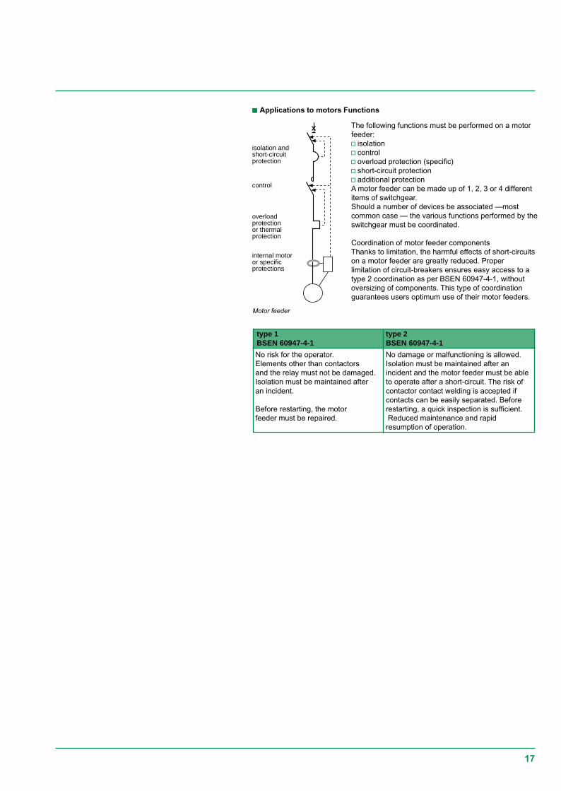
isolation andshort-circuitprotection
control
overloadprotectionor thermalprotection
internal motoror specificprotections
Motor feeder
ccccc Applications to motors Functions
type 1 type 2BSEN 60947-4-1 BSEN 60947-4-1
No risk for the operator. No damage or malfunctioning is allowed.Elements other than contactors Isolation must be maintained after anand the relay must not be damaged. incident and the motor feeder must be ableIsolation must be maintained after to operate after a short-circuit. The risk ofan incident. contactor contact welding is accepted if
contacts can be easily separated. BeforeBefore restarting, the motor restarting, a quick inspection is sufficient.feeder must be repaired. Reduced maintenance and rapid
resumption of operation.
The following functions must be performed on a motorfeeder:v isolationv controlv overload protection (specific)v short-circuit protectionv additional protectionA motor feeder can be made up of 1, 2, 3 or 4 differentitems of switchgear.Should a number of devices be associated —mostcommon case — the various functions performed by theswitchgear must be coordinated.
Coordination of motor feeder componentsThanks to limitation, the harmful effects of short-circuitson a motor feeder are greatly reduced. Properlimitation of circuit-breakers ensures easy access to atype 2 coordination as per BSEN 60947-4-1, withoutoversizing of components. This type of coordinationguarantees users optimum use of their motor feeders.

18
Current limitation curve
Thermal stress limitation curve
Limitation curvesA circuit-breaker s limiting capacity is expressed by limitation curves that give:c the limited peak current as a function of the rms current of the assumed short-circuit current.For example: on a 160 A feeder where the assumed lsc is 90 kA rms, the non-limitedpeak lsc is 200 kA (asymmetry factor of 2.2) and the limited lsc is 26 kA peak.
c the limited thermal stress (in A2s) as a function of the rms current of theassumed short-circuit current.For example: on the previous feeder, the thermal stress moves from more than 100106 A2s to 6 106 A2s.
The implementation techniques
kA
90 kA
200
26 limited peak Isc
assumed rms Isc
peak
kA rms
A s2
90
limitedthermalstress
assumedrms Isc
kA rms

19
Cascading provides circuit-breakers placed downstream of a limiting circuit-breakerwith an enhanced breaking capacity. The limiting circuit-breaker helps the circuit-breaker placed downstream by limiting high short-circuit currents. Cascading makesit possible to use a circuit-breaker with a breaking capacity lower than the short-circuit current calculated at its installation point.
Area of applicationCascading:c concerns all devices installed downstream of this circuit-breaker,c can be extended to several consecutive devices, even if they are used in differentswitchboards.
The installation standards (BS 7671 or IEC 364) stipulate that the upstream devicemust have an ultimate breaking capacity lcu greater than or equal to the assumedshort-circuit current at the installation point.For downstream circuit-breakers, the ultimate breaking capacity lcu to be consideredis the ultimate breaking capacity enhanced by coordination.
PrinciplesAs soon as the two circuit-breakers trip (as from point lB), an arc voltage UAD1 onseparation of the contacts of D1 is added to voltage UAD2 and helps, by additionallimitation, circuit-breaker D2 to open.
Cascading is used to:c make savings,c simplify choice of protectiondevices, by using circuit-breakerswith standard performance.
t (s)
IB Icu(D2 + D1)
D2 D1
I
Icu(D2)
D1
D2 I
t1
Icc
UAD2IB
t1' t2
UAD1
UAD2
UAD1
t (ms)
Cascading

20
D1 helps D2 to break the currentlimitation of D2 enhanced by D1limitation of D2limitation of D1
IcuD2/enhancedIcuD2
Icc (D)
I
1I
D1
D2
The association D1 + D2 allows an increase in performance of D2 as shown infigure 2:c limitation curve D2,c enhanced limitation curve of D2 by D1,c lcu D2 enhanced by D1.
In actual fact, in compliance with the recommendations of BSEN 60947-2,manufacturers give directly and guarantee lcu enhanced by the association of D1 +D2.
AdvantagesCascading allows benefit to be derived from all the advantages of limitation. Thus,the effects of short-circuit currents are reduced, i.e.:c electromagnetic effects,c electrodynamic effects,c thermal effects.
Installation of a single limiting circuit-breaker results in considerable simplificationsand savings for the entire downstream installation:c simplification of choice of devices by the cascading tables,c savings on downstream devices. Limitation enables circuit-breakers with standardperformance to be used.
The implementation techniques

21
D1
D2
0 IsD2Ir
D1 and D2trip
I faultD2 onlytrips
I fault
Discrimination of protectiondevices is a key factor incontinuity of supply.Discrimination is:c partial,c or total,according to the characteristicsof the association of protectiondevices.The discrimination techniquesimplemented are:c currentc timec logic.Discrimination can be optimisedby use of current limitingdownstream circuit-breakers.
General information
PrincipleReminder (see paragraph 1.4. "standard BSEN 60947-2").Discrimination consists of providing coordination between the operatingcharacteristics of circuit-breakers placed in series such that should a downstreamfault occur, only the circuit-breaker placed immediately upstream of the fault will trip.A discrimination current ls is defined such that:lfault > ls: both circuit-breakers trip,lfault < ls: only D2 eliminates the fault.
ccccc Discrimination qualityThe value ls must be compared with assumed lsc(D2) at point D2 of the installation.v total discrimination: ls > lsc(D2); discrimination is qualified as total, i.e. whateverthe value of the fault current, D2 only will eliminate it.v partial discrimination: ls < lsc(D2); discrimination is qualified as partial, i.e. up to ls,only D2 eliminates the fault. Beyond ls, both D1 and D2 open.
ccccc Manufacturer s dataIn actual fact, manufacturers give discrimination quality intrinsically, i.e.:v total discrimination, if ls is equal to lcuD1 (the association will never be able to seea fault current greater than this value),v partial discrimination, limited to ls. This value ls can nevertheless be greater thanlsc(D2). Seen by the user, discrimination is then total.
ccccc Glossaryv lsc(D1): Short-circuit current at the point where D1 is installed,v lcuD1: Ultimate breaking capacity of D1.
Discrimination

22
The discrimination limit ls is:- ls = lsd2 if the thresholds lsd1 and lsd2 are too close or merge,- ls = lsd1 if the thresholds lsd1 and lsd2 are sufficiently far apart.As a rule, current discrimination is achieved when:- lr1 / lr2 < 2- lsd1 / lsd2 > 2The discrimination limit is- ls = lsd1.
Discrimination qualityDiscrimination is total if ls > lsc(D2), i.e. lsd1 > lsc(D2).This normally implies:v a relatively low level lsc(D2),v a large difference between the ratings of circuit-breakers D1 and D2.Current discrimination is normally used in final distribution.
ccccc Time discriminationThis is the extension of current discrimination and is obtained by staging over time ofthe tripping curves. This technique consists of giving a time delay of t to the ShortTime (ST) tripping of D1.
Discrimination techniques
c Current discriminationThis technique is directly linked to the staging of the Long Time (LT) tripping curvesof two serial-connected circuit-breakers.
The thresholds (lr1, lsd1) of D1 and (lr2, lsd2) comply with the staging rules ofcurrent discrimination.The discrimination limit ls of the association is at least equal to li1, the instantaneousthreshold of D1.
D1
D2
Isd 2 Isd 1Ir2 Ir1
t D2 D1
I
Ir1
D1
D2
Isd 2 Isd 2Ir2 Isd 1
∆t
t D2 D1
Id

23
Ic
ILdId
Id
non-limiting
short-circuitlimiter
Isc (D2)
Discrimination qualityThere are two possible applications:c on final and/or intermediate feeders.A category circuit-breakers can be used with time-delayed tripping of theupstream circuit-breaker. This allows extension of current discrimination up to theinstantaneous threshold li1 of the upstream circuit-breaker: ls > li1.If lsc(D2) is not too high — case of a final feeder - total discrimination can beobtained.c on the incomers and feeders of the MSBAt this level, as continuity of supply takes priority, the installation characteristicsallow use of B category circuit-breakers designed for time-delayed tripping. Thesecircuit-breakers have a high thermal withstand (lcw > 50% lcn for t = 1s): ls > lcw1.Even for high lsc(D2), time discrimination normally provides totaldiscrimination: lcw1 > lsc(D2).
NB: Use of B category circuit-breakers means that the installation must withstandhigh electrodynamic and thermal stresses.Consequently, these circuit-breakers have a high instantaneous threshold li that canbe adjusted and disabled in order to protect the busbars if necessary.
In fact, when referring to the figure, a fault current ld will be seen by D1:vvvvv equal to ld for a non-limiting circuit-breaker,vvvvv equal to lLd < ld for a limiting circuit-breaker.The limit of current and time discrimination ls of the association D1 + D2 is thuspushed back to a value that increases when the downstream circuit-breaker is rapidand limiting.
Discrimination qualityUse of a limiting circuit-breaker is extremely effective for achievement of totaldiscrimination when threshold settings (current discrimination) and/or theinstantaneous tripping threshold (time discrimination) of the upstream circuit-breaker D1 are too low with respect to the fault current ld in D2 — lsc(D2).
c enhancement of current and time discriminationvvvvv limiting downstream circuit-breakersUse of a limiting downstream circuit-breaker enables the discrimination limit to beincreased.

24
D1
D2
D3
pilot wire
interlockingorder
interlockingorder
The implementation techniques
This type of discrimination can be achieved with circuit-breakers equipped withspecially designed electronic trip units (Compact, Masterpact): only the Short TimeProtection (STP) and Ground Fault Protection (GFP) functions of the controlleddevices are managed by Logic Discrimination. In particular, the InstantaneousProtection function — inherent protection function — is not concerned.
Settings of controlled circuit-breakersc time delay: there are no rules, but staging (if any)of the time delays of timediscrimination must be applied(tD1 > tD2 > tD3)c thresholds: there are no threshold rules to be applied, but natural staging of theprotection device ratings must be complied with (lcrD1 > lcrD2 > lcrD3).NB: This technique ensures discrimination even with circuit-breakers of similarratings.
PrinciplesActivation of the Logic Discrimination function is via transmission of information onthe pilot wire:c ZSI input:v low level (no downstream faults): the Protection function is on standby with areduced time delay (< 0.1 s).v high level (presence of downstream faults): the relevant Protection function movesto the time delay status set on the device.c ZSI output:v low level: the trip unit detects no faults and sends no orders.v high level: the trip unit detects a fault and sends an order.
OperationA pilot wire connects in cascading form the protection devices of an installation (seefigure showing logic discrimination). When a fault occurs, each circuit-breakerupstream of the fault (detecting a fault) sends an order (high level output) and movesthe upstream circuit-breaker to its natural time delay (high level input). The circuit-breaker placed just above the fault does not receive any orders (low level input) andthus trips almost instantaneously.
Discrimination qualityRecommended and extensively used in the USA, this technique enables:v easy achievement as standard of discrimination on 3 levels or more,v elimination of important stresses on the installation, relating to time-delayedtripping of the protection device, in event of a fault directly on the upstreambusbars. All the protection devices are thus virtually instantaneous.v easy achievement of downstream discrimination with non-controlled circuit-breakers.
Logic discrimination
ccccc Logic discrimination or "Logic Discrimination Zone (ZSI)"

25
Isd1
t
Icu D2
Is
Isd1
D1
D2
Ir2
I t2
I
ND
D
Is
D1D2
IIr2 currentdiscrimination
timediscrimination
General discrimination rulesOverload protectionFor any overcurrent value, discrimination is guaranteed on overload if the non-tripping time of the upstream circuit-breaker D1 is greater than the maximumbreaking time of circuit-breaker D2.The condition is fulfilled if the ratio of Long Time (LT) and Short Time (ST) settings isgreater than 2.The discrimination limit ls is at least equal to the setting threshold of the upstreamShort Time (ST) time delay.
Short-circuit protectionc time discriminationTripping of the upstream device D1 is time delayed by t.vvvvv The conditions required for current discrimination must be fulfilled.vvvvv The time delay t of the upstream device D1 must be sufficient for the downstreamdevice to be able to eliminate the fault.Time discrimination increases the discrimination limit ls up to the instantaneoustripping threshold of the upstream circuit-breaker D1.Discrimination is always total if circuit-breaker D1:vvvvv is of category B,vvvvv has an lcw characteristic equal to its lcu.Discrimination is total in the other cases if the instantaneous tripping threshold of theupstream circuit-breaker D1 is greater than the assumed lsc in D2.
c logic discriminationDiscrimination is always total.
c general caseThere are no general discrimination rules.vvvvv The time/current curves clearly supply a value of lsc (limited or assumed) less thanthe Short Time tripping of the upstream circuit-breaker; discrimination is then total.
If this is not the case,only tests can indicatediscrimination limits ofcoordination, in particularwhen circuit-breakers areof the limiting type. Thediscrimination limit ls isdetermined bycomparison of curves:vvvvv in tripping energy forthe downstream circuit-breaker,vvvvv in non-tripping energyfor the upstream circuit-breaker.The potential intersectionpoint of the curves givesthe discrimination limit ls.
The manufacturersindicate in tables thetested performance ofcoordination.
The discrimination rules

26
According to the Earthing System, discrimination only uses coordination ofovercurrent protection devices. When the insulation fault is treated specifically byearth leakage protection devices (e.g. in the TT system), discrimination of theresidual current devices (RCDs) with one another must also be guaranteed.
Discrimination of earth leakage protection devices must ensure that, should aninsulation fault occur, only the feeder concerned by the fault is de-energised.The aim is to optimise energy availability.
There are two types of earth leakage protection discrimination.
Vertical discriminationIn view of requirements and operating standards, discrimination must simultaneouslymeet both the time and current conditions.
Vertical discrimination
DR
DR
Da
Db
Current condition:The RCD must trip between ln and ln/2, where ln is the declared operating current.There must therefore exist a minimum ratio of 2 between the sensitivities of theupstream device and the downstream device. In practice, the standardised valuesindicate a ratio of 3.
Time condition:The minimum non-tripping time of the upstream device must be greater than themaximum tripping time of the downstream device for all current values.
NB: The tripping time of RCDs must always be less than or equal to the timespecified in the installation standards to guarantee protection of people againstindirect contacts.
The techniques implemented
Earth leakage protectiondiscrimination
-

27
10
20
50100
200
500
tms
1 2 5 10
500 A
Id / I∆n.
G
S max.
Standardised values of operating time
type In I∆∆∆∆∆n standardised values of operating timeA A and non-operating time (in seconds) at:
I∆∆∆∆∆n 2I∆∆∆∆∆n 5I∆∆∆∆∆n 500 Ageneral all all 0,3 0,15 0,04 0,04 maximuminstan- values values operating timetaneousselective >25 >0,030 0,5 0,2 0,15 0,15 maximum
operating time0,13 0,06 0,05 0,04 minimum non
operating time
Horizontal discrimination
Operating time curves G and S
For the domestic area (M9), standards IEC 61008 (residual current circuit-breakers)and IEC 61009 (residual current devices) define operating times.The values in the table correspond to curves G and S.Curve G (General) correspond to non-delayed RCDs and S (Selective) to those thatare voluntarily delayed.
DR DR
Horizontal discriminationSometimes known as circuit selection, it allows savings at the supply end of theinstallation of an RCD placed in the cubicle if all its feeders are protected by RCDs.Only the faulty feeder is de-energised, the devices placed on the other feeders donot see the fault.

28
Installation standard IEC 364 governs electrical installations of buildings. BS7671 theBritish National standard, based on this IEC standard, recommend goodcoordination between the protection switchgear. They acknowledge the principles ofcascading and discrimination of circuit-breakers based on product standardBSEN 60947-2.
c Product standards BSEN 60947-2In appendix A, standard BSEN 60947-2 recognises and defines coordinationbetween circuit-breakers (see paragraph 1.4 page 11). In particular, it defines thetests to be performed.vvvvv discriminationThis is normally studied on a theoretical level. For critical points where trippingcurves overlap, it must be verified by tests. It is guaranteed by the manufacturer whowill record the value of ls (discrimination limit) in tables.vvvvv cascading or coordination of the back-up protection deviceThe standard indicates the measurements to be taken to verify this coordination.- Verification by comparison of characteristicsIn practical cases, this type of verification is sufficient. It must be clearly proved thatthe lcuD2 of the association is compatible with the maximum energy l2t acceptableby D2.- Verification by testsCascading is normally verified by tests for critical points. The tests are performedwith an upstream circuit-breaker D1 with a maximum overcurrent setting and adownstream circuit-breaker D2 with a minimum setting. The test results (breakingcapacities enhanced by cascading) are in a table and guaranteed by themanufacturer.
c Installation standardsBS 7671 national installation standards specify the implementation of theseprinciples as per the Earthing System considered, in accordance with standardIEC 364.
DiscriminationDiscrimination is defined and established for all Earthing Systems used andtypes of fault (overload, short-circuit, insulation fault). However, in event of aninsulation fault in the IT system, the advantage of continuity of supply is provided bythe actual system that tolerates the 1st fault. This advantage must be maintained by asearch and rapid elimination of this fault.
CascadingOn the other hand, cascading rules are given for a TN or TT type earthingsystem.
Basic rules in TT system:Cascading rules cannot apply for an IT system due to the double insulation fault. Thefollowing rules must be implemented:vvvvv the circuit-breaker must have a breaking capacity that is greater than or equal tothe three-phase short-circuit current at the point considered,vvvvv in event of a assumed double fault, it is laid down that the double fault short-circuitcurrent will be at most:- 15% of three-phase lsc for a three- phase lsc < 10 000 A,- 25% of three-phase lsc for a three-phase lsc > 10 000 A.
Coordination of protection devices andinstallation standards
Discrimination and cascading canonly be guaranteed by themanufacturer who will record histests in tables.
The techniques implemented

29
L1L2L3N
PE
L1L2L3NPE
NB: Standard BS 7671 defines 3 types of earthing systems. In short:c TT: The neutral point of the LV transformer is earthed. The equipment frames areconnected to a separate earth.c TN: The neutral point of the LV transformer and the equipment frames areconnected to the same earth.c IT: The neutral point of the LV transformer is unearthed. The equipment frames areearthed.The earthing systems (and associated automatic breaking techniques) have beendefined to guarantee protection of people against indirect contacts.
L1L2L3NPE
IT system
TN system
TT system

30
The Merlin Gerin and Telemecanique circuit-breaker ranges cover all therequirements of LV electrical power distribution from 0.5 to 6300 A, i.e.:c the Merlin Gerin 630 to 6300 A Masterpact and power circuit-breaker ranges,c the range of Compact moulded case circuit-breakers (MCCB):v Compact CM from 1250 to 3200 A,v Compact C from 800 to 1250 A,v Compact NS from 100 to 630 A,c the 0.5 to 125 A Multi 9 NG125, C60, DPN miniature circuit-breaker ranges,c the Telemecanique Integral/GV2/GV7 motor protection circuit-breaker ranges.
These products meet product standards BSEN 60947-2.
The Merlin Gerin and Telemecanique distribution and motor protection circuit-breakerranges have been developed coherently. Their coordination has been tested as perBSEN 60947-2 and is guaranteed by Schneider Electric. The complete tables givingcoordination, cascading and discrimination of circuit-breakers are available.
Range of circuit breakers

31
For power circuit-breakers
The technologies of Merlin Gerin Masterpact range ideally meets the discriminationneeds at the supply end of the installation as well as specific limitation requirementsrelating to certain applications.
The selective pole technologyImportant discrimination requires enhancement of the switchgear s electrodynamicwithstand, using the own current compensation effect.
Contact pressure isproportional to l2 in theloop.
This technology is used in all the Masterpact NW.
The limiting pole technologyA high limiting capacity is enabled by:c a fixed pole with current loop and magnetic U,c one axis of the moving pole positioned at its end.
Masterpact and NW and H1This performance is ideal on the most common industrial and large commercial sites(lsc < 65 kA). It guarantees total discrimination with the downstream Compact NScircuit-breakers.
For this performance, breaking capacity is equal to thermal withstand lcs = lcw.
This allows the switchgear to withstand the maximum short-circuit current throughoutthe short time delay.Masterpact NW H2
Electromagnetic compensation
1/3
2/3
i
iA
i
Frdfm
Fm
When the short-circuit level at the device installation point is greater than its thermalwithstand, its breaking capacity must be greater than its thermal withstand lcs > lcw.
An internal protection is now required to prevent the switchgear being damaged. Thisis an instantaneous tripping device set in the factory to a threshold just belowelectrodynamic withstand (EDW).
I65 kA
NW H1
total time discrimination
Icu = Ics = electrodynamic withstand Icw

32
TED
t
Isc
Accuracy zoneof theinstantaneoustripping threshold(± 10 %)
85 kAI
100 kA
Ics = Icu
NW H2
Icw = thermal withstand = self-protection DIN threshold
maximum time discrimination
Accuracy zone of the instantaneous tripping threshold (+/- 10%)
Limited time discrimination
Widespread use of air current transformers enables, thanks to more accuratemeasurement (no saturation) the thermal withstand threshold to be approached, thusmarkedly enhancing the discrimination level by delaying instantaneous tripping.
For large industrial sites (lsc < 100 kA), this performance guarantees totaldiscrimination with the downstream Compact NS.

33
Half moon activating the pole shaft
Effort sensor
Kinematic chain
Masterpact NW H3Just as for the Masterpact H2, the level of performance lcs > lcw also requirescalibration of instantaneous tripping.
In order to break an assumed fault current of 150 kA, very early action is required. Itis impossible to wait for passage of the first fault current wave as the device sthermal withstand is far lower.
The technology of the electronic measurement channel associated with themechanical action of the tripping coil does not allow a sufficiently fast reaction. Thetechnology used in Masterpact NW circuit-breakers has been patented.
When a high short-circuit current appears, it creates an electromagnetic force thatpushes the pole and moves it apart. The pole movement activates a catch by meansof a kinematic chain. The movement of this catch directly releases the pole shaftbefore intervention of the electronic measurement chain.
This tripping by mechanical system occurs at the same time as the electronicmeasurement chain that will confirm circuit-breaker opening and indicate the frontface fault.This system allows:c a high thermal withstand to be maintained: lcw = 65 kA 1s,c beyond lcw, an ultra fast tripping guaranteeing an lcu up to 150 kA.This performance is ideal for multisource installations with a high short-circuit current(> 100 kA) on the main busbar and for which continuity of supply is essential.Discrimination with the downstream Compact NS is total as standard.
Masterpact NWThe Masterpact NW L1 combines all performances:c a breaking capacity up to 200 kA/400 V for the UL range,c a thermal withstand of 37 kA/400 V,c an important limiting capacity (NW L1 assumed lsc = 390 kA to 380/415 V, limitedlsc = 170 kA).
It therefore uses the technologies described above:c selective pole like the other switchgear in order to reach a thermal withstandof 30 kA/400 V,c automatic unlatching of the circuit breaker operating mechanism to produce ultrafast tripping.

34
Magnetic U
t
t
UM
ts
I
U
EM
Ua
e
Prospectiveshort-circuitcurrent
Limited current
Total breaking time
Intervention time
To obtain a high limiting capacity, the fixed pole has been modified. This modificationhas been patented.
Limiting capacity depends on the arc voltage created between the fixed pole and themoving pole on opening. It must be established early on and quickly increase to ahigh value.
For this purpose, repulsion force must be increased and arc projection encouragedin the arc chute.
c Use of a U-shaped current loop to increase the repulsion force.
c Use of a magnetic U around the fixed pole to concentrate field lines and project thearc in the arc chute, early on, quickly and high.

35
Ua
Arc chute
Magnetic U
U-shapedcurrent loop
On a high short-circuit, the poles open very slightly and the magnetic U then projectsthe arc in the arc chutes. The fault current is diverted. The automatic unlatching ofthe circuit breaker operating mechanism then quickly opens the circuit-breaker.
This performance meets the limitation needs of fault currents while at the same timeguaranteeing an unmatched level of discrimination of 37 kA for this circuit-breakertype.
To enhance breaking performance and obtain a high short-circuit current limitationon devices theoretically not very limiting, a trip unit is used, not based on theinstantaneous value of the current but on a drift whose peculiarity is not to trip on thefirst fault current half wave. When a short-circuit current appears, the downstreamcircuit-breaker opens as soon as the fault current is greater than its trippingthreshold and eliminates the fault in less than one half-wave.

36
Arc chute
Short-circuitcurrent
PistonArc
Arc
Fixedcontact
Movingcontact
Arc chute
Breakingenclosure
Arc chute
Fixedcontact
The Merlin Gerin and Telemecanique moulded case circuit-breaker (MCCB) rangesare designed to provide users with maximum energy availability. The MCCB:c give an optimum response to discrimination problems,c are very limiting, even on high short-circuits, in order to drastically reduce stresseson intermediate distribution.
The 100 to 630 A Compact NS range is mainly used:c to protect intermediate distribution,c to protect lines supplying large loads.This range implements an innovating technique: roto-active breaking.
This high current limiting technique uses a new tripping energy, pressure, resultingfrom arc energy.Its operation is described below:c Each circuit-breaker pole has an enclosure in which a rotating contact generates,by electromagnetic repulsion, two serial arcs on occurrence of the short-circuitcurrent.c A piston and spring device uses the pressure from arc energy to cause — beyond acertain threshold (roughly 35 ln) — a reflex tripping, roughly 3 ms after contactrepulsion.c Up to this threshold, pressure is not sufficient to cause tripping and arc impedancelimits the short-circuit current.c Beyond this threshold, breaking is very quick (1 ms) and limits still further theshort-circuit current.The enclosure parts are sized to match circuit-breaker size.Consequently, limitation is greatest when rating is smallest.This technique provides Compact NS with an outstanding limiting capacity andthus with increased discrimination possibilities.This technique is also very useful for limiting stresses on electrical powerdistribution.
Trip unitsThe Compact NS are equipped with a thermal magnetic or electronic type trip unit.Setting of the Long Time (LT) thresholds ensures current discrimination.Short Time (ST) protection has as standard a mini time delay of 5 to 7 ms accordingto sizes allowing time discrimination for short-circuits of average value beyond theShort Time (ST) tripping threshold of the upstream circuit-breaker D1.
For moulded case circuit-breakers(MCCB)
Roto-active breaking: repulsion of contacts Roto-active breaking: tripping bypressure

37
For miniature circuit-breakers
The Merlin Gerin C60H/NG125 Miniature circuit-breaker ranges have the necessaryperformance and characteristics to meet final distribution requirements:
Fm
i
i
i
c a nominal rating of 0.5 to 125 A,c a breaking capacity of up to 50 kA as perBSEN 60947-2,c tripping curves B, C, D and MA,c simple, safe installation system on DIN rail,c Vigi module can easily be clipped onto the protectiondevices,c C60H is also available as a singe pole wide Rcbo,The Multi 9 circuit-breakers are designed accordingto magnetic actuator principles, thus allowing veryquick development of arc voltage.

38
D1
100 kA
NW20 H2
D2
l=20 m
60 kA
NW40 H2
Busbar
Total discrimination
D1
D2
NW20 H2
100 kABusbar
Discrimination limited to 86 kA
General discrimination rules (in distribution)c Overload protectionvvvvv upstream and downstream circuit-breakers equipped with a thermal magnetic tripunit.The current discrimination of Merlin Gerin and Telemecanique circuit-breakers isprovided if the ratio of the tripping thresholds:- thermal is greater than 1.6- magnetic is greater than 2.vvvvv upstream circuit-breaker equipped with an electronic trip unit and downstream .circuit-breaker equipped with a thermal magnetic trip unit.Current discrimination of the Merlin Gerin and Telemecanique circuit-breakers isprovided if the ratio of the tripping thresholds:- Long Time (LT) and thermal is greater than 1.6(*) to 2.5,- Short Time (ST) and magnetic is greater than 1.5.vvvvv upstream and downstream circuit-breakers equipped with an electronic trip unit.Current discrimination of the Merlin Gerin and Telemecanique circuit-breakers isprovided if the ratio of the tripping thresholds:- Long Time (LT) is greater than 1.2(*) to 1.6,- Short Time (ST) is greater than 1.5.(*) Upstream trip unit equipped with a time-delayable LT threshold.
c Short-circuit protectionv time discriminationTime discrimination of Merlin Gerin and Telemecanique circuit-breakers is providedas soon as there is a difference of one time delay band between the upstream andthe downstream device.v logic discriminationDiscrimination is always total.
Discrimination rules for Masterpact NWc Masterpact NW of the H1 typeTime discrimination is always total with a Masterpact H1 upstream (lcw = lcu)regardless of the circuit-breaker placed downstream.c Masterpact NW of the H2 and H3 typeTime discrimination is provided up to the thermal withstand threshold, i.e.:vvvvv 86 kA for a Masterpact NW H2,vvvvv 65 kA for a Masterpact NW H3.At the MSB:- discrimination is partial (figure 1) between an incomer D1 and a feeder D2.- discrimination is often total (figure 2) between a feeder D1 and a device D2 placedin a subdistribution switchboard at some distance.
The Masterpact circuit-breakersprovide total discrimination withall the downstream circuit-breakersif the 4 following conditions aremet:c the ratio between Long Timesettings of the 2 devices is 1.6,c the ratio between Short Timesettings is 1.5,c the intentional time delay settingsare compatible,c setting of the instantaneousthreshold, if any, must be on OFF.
The discrimination rules from 1 to 6300 A

39
Tripping curves of a Compact NS100 and 250 and discrimination types
"Natural" discrimination rules between Compact NSc Discrimination between distribution circuit-breakersWith Compact NS, simple discrimination rules can be drawn up due to the newimplementation techniques.
c Overload protection: current discriminationAs in the general case, current discrimination between Compact NS circuit-breakersis provided if the ratio of the tripping thresholds:- Long Time (LT) is greater than 1.2 to 2.5,- Short Time (ST) is greater than 1.5 to 2,according to the types of trip units equipping the devices.
c Low value short-circuit protection:time discrimination:Tripping of the upstream device D1 is slightly time delayed up to reflex tripping.Consequently, as the downstream circuit-breaker is of a lower rating — current size —it will be far quicker and will break in a time less than the time delay of the upstreamcircuit-breaker.This discrimination, of the time type, is applicable up to reflex tripping of theupstream device (roughly 35 ln).The protection between Compact NS is selective if the ratio between the physicalsizes (ratings) of the circuit-breakers is greater than 2.5.
c High value short-circuit protection: energy discriminationThe breaking technique developed in Compact NS — outstanding limitation and reflextripping- allows natural staging of D2 tripping and D1 non-tripping energy curves.
c PrincipleWhen a very high short-circuit is detected by circuit-breakers D1 and D2, the devicecontacts open slightly at the same time, thus limiting current.ccccc The arc energy, high at D2, causes it to trip.ccccc The arc energy, limited at D1, is not sufficient for it to trip.As a result, as the downstream circuit-breaker is of a lower rating — current size — itwill be more limiting. It will break with a current limitation such that the fault energy ismarkedly less than the tripping threshold of the upstream circuit-breaker.
D1
D2
I t2
Icu1
NDD
Icu2
D
D1
D2
Ix 100 A
t (s)
10000
NS 100100 A
NS 250250 A
1000
100
10
1
.1
.01
.001.5 1 10 100 300
This technique allows rules for discrimination between devices to be standardised.Protection between Compact NS is selective if the ratio between physical sizes(ratings) of the circuit-breakers is greater than 2.5.
In the extension of current and time discrimination, this discrimination is known as"energy discrimination".

40
D1
D2
I t2
Icu1
NDD
Icu2
D1RC
D D2
Currentdiscrimination
Timediscrimination
Energydisrimination
Discrimination enhanced by cascading with the Compact NSWith traditional circuit-breakers, when cascading is implemented between twodevices, discrimination is obtained by tripping of the upstream circuit-breaker D1 tohelp downstream circuit-breaker D2 to break the current. The discrimination limit hasa value ls at most equal to the breaking capacity lcuD2 of the downstream circuit-breaker.In the case of Compact NS type circuit-breakers, the breaking techniqueimplemented on high short-circuit currents increases the discrimination limit.c The Compact NS downstream D2 sees a very high short-circuit current. Reflextripping causes it to trip very quickly (< 1 ms) with a very great limitation of the faultcurrent.c The Compact NS upstream D1 sees a very limited fault current. This currentgenerates repulsion of the contacts/RC curve, resulting in an arc voltage limiting stillfurther the short-circuit current. However arc pressure is not sufficient to cause reflextripping.Thus the Compact NS D1 helps the Compact NS D2 to break the current withouttripping.The discrimination limit ls can exceed the breaking capacity lcuD2 of thedownstream circuit-breaker and reach the breaking capacity enhanced bycascading.
Discrimination then becomes total with an optimised device cost
UA D2
UA D1
D1
D1
D2
D2ID/IN2
PD2
ID/IN1
t
t
t
t
ts t's
PD1
ts
ts t's
Reflexe
Reflexe
Discrimination enhanced by cascading: principle Discrimination enhanced by cascading: curves
Advantage of Total Discrimination as standard with Compact NSThe immediate advantage is making total discrimination with Compact NS naturalas soon as:v staging of the LT and ST settings is greater than or equal to 1.5,v staging of the nominal device ratings is greater than or equal to 2.5.The figure above illustrates the three types of discrimination.

41
D1 application D2 ratio between the upstream and downstream settingsthermal protection magnetic protectionupstream lr / downstream lr upstream lm / downstream lm
TM…D Distribution TM…D u 1,6 u 2STR…SE/GE u 1,6 u 1,5
Motor MA + separate thermal relay u 3 u 2motor thermal magnetic u 3 u 2STR…ME u 3 u 1,5
STR…2 or 3 Distribution TM…D u 2,5 u 1,5fixed LT time delay STR…SE/GE u 1,6 u 1,5
Motor MA + separate thermal relay u 3 u 1,5motor thermal magnetic u 3 u 1,5STR…ME u 3 u 1,5
Micrologic 2.0, 5.0, 6.0 and 7.0 Distribution TM…D u 1,6 u 1,5STR...4, 5 or 6 STR…SE/GE, Micrologic u 1,2 u 1,5adjustable LT time delay Motor MA + separate thermal relay u 3 u 1,5shifted on the upper band motor thermal magnetic u 3 u 1,5with respect to the downstream STR…ME, Micrologic u 3 u 1,5protection
Discrimination of circuit-breakers in motor protection
M
D2
MM
D1
Specific applicationsComparison with fusesThis rule can be compared with that used for fuse combinations when the ratio of thecurrent ratings must be greater than 1.6.However, compared with fuse combinations:c distribution circuit-breaker,c the enhanced discrimination tables, depending on test results, often make itpossible to come down to comparable ratios,c the possibility of obtaining discrimination and cascading with downstream circuit-breakers (enhanced discrimination),c motor protection circuit-breaker,c motor protection circuit-breakers are ideally sized for the motor rating, whereas thefuse must be oversized with respect to motor nominal rating.
The combination benefits from all the possibilities offered by the additional integratedfunctions relating to circuit-breakers. The discrimination ratio is then equivalent.
In this sense, the Compact NS combine the following:c qualities of fuses with respect to high short-circuits,c qualities naturally greater for treating overload faults and low value short-circuits,discrimination rules,c advantages relating to additional functions and the communication potential ofcircuit-breakers.
Discrimination between a distribution circuit-breaker and a protection circuit-breakerThe qualities of the Compact NS enable them to be used in motor protection.
SummaryThe following table summarises the conditions to be met to obtain totaldiscrimination

42
The tables in section 3 show the discrimination possibilities of the Merlin Gerincircuit-breakers with one another.Depending on whether or not there is cascading, the results come from acomparison of characteristics or tests.
Conditions of useConditions of use are specified: circuit-breakers can be used in distribution or motorprotection.
Reading the tablesThe shaded boxes and boxes containing a "T" correspond to total discriminationbetween the relevant upstream and downstream circuit-breakersunder all faultconditions.For the other boxes, discrimination is either partial (indicated discrimination limit) orthere is no discrimination (boxes with no value mentioned).
Tables of discrimination enhanced by cascading with Compact NSWith Compact NS type circuit-breakers, the cascading implemented between twodevices increases the discrimination limit.This can consequently reach the breaking capacity enhanced by cascading anddiscrimination then becomes total.This is expressed in enhanced discrimination tables with these circuit-breakerssee page 45.
Discrimination tables
The tables in section 3 give,in 220/240 V and 400/415 V phase-to-phase distributionand then in motor protection, the cascading possibilities according to BSEN 60947-2between circuit-breakers:c Multi 9 with Multi 9,c Compact NS, Compact, Masterpact with Multi 9 and with one another.For circuit-breakers used in single-phase on a TN system, the 220/240 V table isused.
NB: The cascading tables are given for an earthing system of the TN or TT type.They do not apply to the IT systems.
Case of several parallel-connected transformersIn this case, specific tables must be used which give the types of circuit-breaker tobe installed on the source feeders and on the main feeders in the case of 2 or 3parallel-connected transformers.They are drawn up with the following assumptions:c short-circuit power of the upstream network of 500 MVA,c coupled transformers are identical (20 kV/410 V) and have a standard short-circuitvoltage,c the short-circuit current on the busbar does not allow for link impedances (mostunfavourable case),c the conditions for parallel-connecting of transformers are met, i.e. the transformershave:v the same Usc,v the same ratio,v a ratio of powers < 2.lsc is given for information, it may vary according to the Usc as a % given by thetransformer manufacturers. The values of the breaking capacities enhanced bycascading are thus given for higher values.
Cascading tables
Implementation of discrimination and cascading

43
Study of MV/LV discrimination from1 to 6300 A
Simplified diagram of a standard installation covering most of the cases observed in practice.
The figure shows the implementation of the coordination of the various protectiondevices in a HV/LV distribution.
Level 1
Level 2
Level 3
NW16H1 Micrologic 5.0level 1a
NS400H
C1001Hlevel 1b
powerdistributionswitchboard
distributionswitchboard
mainswitchboard
sub distributionswitchboardNS100N
Mv protection
non-priorityfeeders
distributionenclosure
distribution
lighting, heating, etc
building utilities
1000 kVA
1000 A
M M
100 A400 A
100 A 160 A
75 kW
16 A
20 kV/400 V1000 kVA
1600 A
1000 kVA
19 kA
45 kA
60 kA
23 kA70 kA
C60H
NS100N/NS160N
1
2
3
4
5
distributionworkshop 1
priority feeders

44
At the Main switcboard Levelccccc Discrimination with the HVThe 2 protection devices are in "series". Consequently, the advantages of continuityof supply linked to discrimination between protection devices do not appearinteresting. Nevertheless, the main advantage of HV/LV discrimination is thatresumption of operation is less restrictive in LV (accessibility, padlocking).Comparison of the tripping curves brought to the secondary of the HV/LVtransformer shows that discrimination between the Masterpact NW16 and theupstream is:v total: if the Masterpact has a tripping without intentional time delay,v almost total: if the Masterpact NW has a tripping with intentional time delay atband 0,1 (Micrologic 5.0 A at 0.4 ON at 0.1 ON), at worst the discrimination limit is at23 kA (1).
1) The parallel-connection of 2 transformers creates an lsc on the common BB of70 kA, but each source transformer only sees an lsc of 23 kA.NB: discrimination is total with an upstream HV circuit-breaker.
ccccc Discrimination with the downstream LV partAccording to the rule laid down on page 36, the Masterpact NW16H1 circuit-breakerat band 0.1 is completely selective with all the downstream circuit-breakers:v if they have an intentional time delay one band lower. In this case, they must nothave an intentional time delay (band 0),v if the ratio of ratings is < 1.3.Consequently, the Masterpact NW16H1 is totally selective with the downstreamC1001H.
CascadingThere is no cascading between the NW16H1 and C1001H circuit-breakers.
Implementation of discrimination and cascading
1
2
10 0005 000
2 000
1 000
500
200100
50
28
10
5
2
1.5
.2
.005
.002
0,3 kA 1,6 kA 8 kA
t(s)
IBTIcc = 23 kA
NW16H1Micrologic 5.0Atsd = 0,1 s ON
Ii OFF
.01
.02
.1min
max delay 0,4
delay 0,1delay 0
D123 kA
F1
20 kV1000 kVA400 V

45
At the power distribution switchboardc Cascading between the C1001H and the NS400/NS100, by enhancing thebreaking capacity of the NS, enables use of N type NS.c The discrimination tables show that use of N type NS circuit-breakers is "totallyselective" with the C1001H. This discrimination is limited to the intrinsic breakingcapacity of the downstream device, i.e. respectively 25 kA for the NS100Nand 45 kA for the NS400N.
At installation level (figure on page 41), the NS100 supplies non-priority feeders.Consequently, implementation of a Compact NS100 of the N type ensuringdiscrimination up to 25 kA is an optimised protection solution.On the other hand, the NS400 supplies loads requiring a high electrical poweravailability. Total discrimination for the user, i.e. up to the assumed lsc level, isnecessary. An H type NS400 must then be installed, that provides this performancedue to the very great limiting capacity of this circuit-breaker.
At the subdistribution switchboardDownstream of the NS400H circuit-breaker, coordination with the NS160N circuit-breaker is provided thanks to enhanced cascading:c with enhancement of breaking capacity of the NS160N (up to 70 kA),c enhancement of discrimination (up to the enhanced breaking capacity of NS160N,i.e. 70 kA).Discrimination is total.
Motor protection circuit-breakerCoordination with upstream distributionThe motor power (75 kA) requires at 400 V a protection by an NS160 MA circuit-breaker set at 150 A. Coordination performance is identical to that established fordistribution protection, i.e.c enhancement of breaking capacity of the NS160 MA,c with enhancement of discrimination (up to the enhanced breaking capacity ofNS160 MA, i.e. 70 kA).
Coordination at motor feeder levelThe limiting qualities of the NS160 circuit-breaker results in a type 2 coordinationwith standard components: Telemecanique contactors and thermal protection relay.This coordination is guaranteed by Schneider Electric.
NB: Protection by fuse results in oversizing of the motor feeder components toobtain a type 2 coordination.
At the final distribution switchboardDespite the lsc level, at this point of the installation, coordination performancebetween the Compact NS and M9 ranges ensures total discrimination using astandard C60H.
Total discrimination of this installation was provided between:c HV and LV,c on 5 stages of LV distribution
Schneider Electric also provides a software to assist with defining circuit-breakers,Ecodial. It optimises choice of circuit-breakers and their settings according to theinstallation type.
3
4
5

46
Cascading, and enhanced discriminationUpstream: Compact NS100 to C1251HDownstream: Circuit breaker Multi 9/Integral/GV2/Compact NS100 to 630
With traditional circuit breakers, cascading between two devices generally results inthe look of discrimination.
With Compact NS circuit breakers, the discrimination characteristics in the tablesremain applicable and are in some cases even enhanced. Protection discriminationis ensured for short-circuit currents greater than the rated breaking capacity of thecircuit breaker and even, in some cases, for its enhanced breaking capacity. In thelatter case, protection discrimination Ia total, i.e. only the downstream device tripsfor any and all possible faults at its point in the installation.
ExampleConsider a combination between:c a Compact NS250N with trip unit TM250Dc a Compact NS100N with trip unit TM100D.
The discrimination tables indicate total discrimination. Protection discrimination istherefore ensured up to the breaking capacity of the NS100N, i.e. 25 kA.The cascading tables indicate an enhanced breaking capacity of 36 kA.
The enhanced discrimination tables indicate that in a cascading configuration,discrimination is ensured up to 36 kA, i.e. for any and all possible faults at that pointin the installation.
Enhanced discrimination tables - 380/415 VFor each combination of two circuit breakers, the tables indicate the:
In a table, a box containing two equal values indicates that discrimination is providedup to the reinforced breaking capacity of the downstream device.
These tables apply only to cases with combined discrimination and cascadingbetween two devices. For all other cases, refer to the normal cascading anddiscrimination tables.
Technical principleEnhanced discrimination is the result of the exclusive Compact NS Roto-activebreaking technique which operates as follows:c due to the short-circuit current (electrodynamic forces), the contacts in bothdevices simultaneously separate. The result is major limitation of the short-circuitcurrentc the dissipated energy provokes the reflex tripping of the downstream device, but isinsufficient to trip the upstream device.
15/25
downstream device breakingcapacity enhanced bycascading (in kA)
selectivity limit enhancedby cascading(in kA)

47
Cascading, and enhanced discriminationUpstream: Compact NS100 to NS250 Trip unit TM-DDownstream: Multi 9
Upstream NS160N NS160H NS160L NS250N NS250H NS250L
Breaking capacity 36 kA 70 kA 150 kA 36 kA 70 kA 150 kA
Trip unit TM-D TM-D TM-D TM-D TM-D TM-D
Downstream Rating 80 100/125/160 80 100/125/160 80 100/125/160 160/200/250 160/200/250 160/200/250C60H 15 kA ≤≤≤≤≤ 16 30/30 30/30 40/40 40/40 40/40 40/40 30/30 40/40 40/40
20 30/30 30/30 40/40 40/40 40/40 40/40 30/30 40/40 40/4025 30/30 30/30 40/40 40/40 40/40 40/40 30/30 40/40 40/4032 15/30 30/30 15/40 40/40 15/40 40/40 30/30 40/40 40/4040 15/30 30/30 15/40 40/40 15/40 40/40 30/30 40/40 40/4050 15/30 30/30 15/40 40/40 15/40 40/40 30/30 30/30 30/3063 30/30 40/40 40/40 30/30 30/30 30/30
NC100H 10 kA 50 25/25 30/30 30/3063 25/25 30/30 30/3080 25/25 30/30 30/30100 25/25 30/30 30/30
NC100LS 36 kA ≤≤≤≤≤ 16 70/70 70/70 100/100 100/100 70/70 100/10020 - 25 70/70 70/70 100/100 100/100 70/70 100/10032 - 40 70/70 70/70 100/100 100/100 70/70 100/10050 - 63 70/70 70/70 100/100 100/100 70/70 100/100
NC100LH 50 kA ≤≤≤≤≤ 16 70/70 70/70 150/150 150/150 70/70 150/15020 - 25 70/70 70/70 150/150 150/150 70/70 150/15032 - 40 70/70 70/70 150/150 150/150 70/70 150/15050 - 63 70/70 70/70 150/150 150/150 70/70 150/150
NG125N 25 kA ≤≤≤≤≤ 16 36/36 36/36 36/36 36/36 70/70 70/70 36/36 36/36 70/7020 - 25 36/36 36/36 36/36 36/36 70/70 70/70 36/36 36/36 70/7032 - 40 36/36 36/36 36/36 36/36 70/70 70/70 36/36 36/36 70/7050 - 63 36/36 36/36 70/7080 36/36 36/36 70/70100 36/36 36/36 70/70125 36/36 36/36 70/70
NG125H 36 kA ≤≤≤≤≤ 16 50/50 50/50 100/100 100/100 50/50 100/10020 - 25 50/50 50/50 100/100 100/100 50/50 100/10032 - 40 50/50 50/50 100/100 100/100 50/50 100/10050 - 63 50/50 100/10080 50/50 100/100
Note: respect the basic overload and short-circuit discrimination rules
Upstream: Compact NSC100 TM-D
Downstream: Multi 9Upstream NSC100N
Breaking capacity 18 kA
Trip unit TM-D
Downstream Rating 63 70 80 100C60H 10 kA ≤≤≤≤≤ 16 18/18 18/18 18/18 18/18
20 18/18 18/18 18/18 18/1825 18/18 18/18 18/18 18/1832 6/18 6/18 6/18 8/1840 6/18 6/18 8/1850 6/18 6/1863 6/18

48
Cascading, and enhanced discriminationUpstream: Compact NS160 to NS250 Trip unit STRDownstream: Multi 9
Upstream NS160N NS160H NS160L NS250N NS250H NS250L
Breaking capacity 36 kA 70 kA 150 kA 36 kA 70 kA 150 kA
Trip unit STR22SE STR22SE STR22SE STR22SE STR22SE STR22SE
Downstream Rating 80 160 80 160 80 160 250 250 250C60H 15 kA ≤≤≤≤≤ 16 30/30 30/30 40/40 40/40 40/40 40/40 30/30 40/40 40/40
20 30/30 30/30 40/40 40/40 40/40 40/40 30/30 40/40 40/4025 30/30 30/30 40/40 40/40 40/40 40/40 30/30 40/40 40/4032 30/30 40/40 40/40 30/30 40/40 40/4040 30/30 40/40 40/40 30/30 40/40 40/4050 30/30 40/40 40/40 30/30 30/30 30/3063 30/30 40/40 40/40 30/30 30/30 30/30
NC100H 10 kA 50 25/25 30/30 30/3063 25/25 30/30 30/3080 25/25 30/30 30/30100 25/25 30/30 30/30
NC100LS 36 kA ≤≤≤≤≤ 16 70/70 70/70 100/100 100/100 70/70 100/10020 - 25 70/70 70/70 100/100 100/100 70/70 100/10032 - 40 70/70 100/100 70/70 100/10050 - 63 70/70 100/100 70/70 100/100
NC100LH 50 kA ≤≤≤≤≤ 16 70/70 70/70 150/150 150/150 70/70 150/15020 - 25 70/70 70/70 150/150 150/150 70/70 150/15032 - 40 70/70 150/150 70/70 150/15050 - 63 70/70 150/150 70/70 150/150
NG125N 25 kA ≤≤≤≤≤ 16 36/36 36/36 36/36 36/36 70/70 70/70 36/36 36/36 70/7020 - 25 36/36 36/36 36/36 36/36 70/70 70/70 36/36 36/36 70/7032 - 40 36/36 36/36 70/70 36/36 36/36 70/7050 - 63 36/36 36/36 70/7080 36/36 36/36 70/70100 36/36 36/36 70/70125 36/36 36/36 70/70
NG125H 36 kA ≤≤≤≤≤ 16 50/50 50/50 100/100 100/100 50/50 100/10020 - 25 50/50 50/50 100/100 100/100 50/50 100/10032 - 40 50/50 100/100 50/50 100/10050 - 63 50/50 100/10080 50/50 100/100
Note: respect the basic overload and short-circuit discrimination rules.

49
Cascading, and enhanced discriminationUpstream: Compact NS250 to NS630Downstream: NSC100N, NS100 to NS250
Upstream: Compact NS250Downstream: Compact NS100 to NSA160Upstream NS250N NS250H NS250L NS250N NS250H NS250L
Breaking capacity 36 kA 70 kA 150 kA 36 kA 70 kA 150 kA
Trip unit TM-D TM-D TM-D STR22SE
Downstream Rating 160 200 250 160 200 250 160 200 250 250 250 250NSC100N 18 kA 16 - 100 36/36 36/36 36/36 50/50 50/50 50/50 50/50 50/50 50/50 36/36 50/50 50/50NS100N 25 kA ≤ ≤ ≤ ≤ ≤ 25 36/36 36/36 36/36 70/70 70/70 70/70 150/150 150/150 150/150 36/36 70/70 150/150Trip unit TM-D 40 - 100 36/36 36/36 36/36 36/70 36/70 36/70 36/150 36/150 36/150 36/36 36/70 36/150NS100H 70 kA ≤≤≤≤≤ 25 150/150 150/150 150/150 150/150Trip unit TM-D 40 - 100 36/150 36/150 36/150 36/150NS100N 25 kA Trip unit STR22SE 36/36 36/36 36/36 36/70 36/70 36/70 36/150 36/150 36/150 36/36 36/70 36/150
Trip unit STR22ME 36/36 36/36 36/36 36/70 36/70 36/70 36/150 36/150 36/150 36/36 36/70 36/150NS100H 70 kA Trip unit STR22SE 36/150 36/150 36/150 36/150
Trip unit STR22ME 36/150 36/150 36/150 36/150
Note: respect the basic overload and short-circuit discrimination.
Upstream NS400NNS400HNS400L NS630NNS630HNS630L C801N C801H C1001N C1001H C1251N C1251H45 kA 70 kA 150 kA 45 kA 70 kA 150 kA 50 kA 70 kA 50 kA 70 kA 50 kA 70 kA
Trip unit STR23SE or STR53UE STR23SE or STR53UE STR45AE STR45AE STR45AEDownstream Rating 400 400 400 630 630 630 800 800 1000 1000 1250 1250
NSC100N 18 kA 16 - 100 36/36 50/50 50/50 36/36 50/50 50/50NS100N 25 kA all TM-D-G-MA 45/45 70/70 150/150 45/45 70/70 150/150 50/50 70/70 50/50 70/70 50/50 70/70NS100H 70 kA all TM-D-MA 150/150 150/150NS160N 35 kA all TM-D-MA 45/45 70/70 150/150 45/45 70/70 150/150 50/50 70/70 50/50 70/70 50/50 70/70NS160H 70 kA all TM-D-MA 150/150 150/150NS250N 35 kA all TM-D-MA 45/45 70/70 150/150 50/50 70/70 50/50 70/70 50/50 70/70NS250H 70 kA all TM-D-MA 150/150NS100N 25 kA trip STR22SE 45/45 70/70 150/150 45/45 70/70 150/150 50/50 70/70 50/50 70/70 50/50 70/70
trip STR22ME 45/45 70/70 150/150 45/45 70/70 150/150 50/50 70/70 50/50 70/70 50/50 70/70NS100H 70 kA trip STR22SE 150/150 150/150
trip STR22ME 150/150 150/150NS160N 35 kA trip STR22SE 45/45 70/70 150/150 45/45 70/70 150/150 50/50 70/70 50/50 70/70 50/50 70/70
trip STR22ME 45/45 70/70 150/150 45/45 70/70 150/150 50/50 70/70 50/50 70/70 50/50 70/70NS160H 70 kA trip STR22SE 150/150 150/150
trip STR22ME 150/150 150/150NS250N 35 kA trip STR22SE 45/45 70/70 150/150 50/50 70/70 50/50 70/70 50/50 70/70
trip STR22ME 45/45 70/70 150/150 50/50 70/70 50/50 70/70 50/50 70/70NS250H 70 kA trip STR22SE 150/150
trip STR22ME 150/150NS400N 45 kA trip STR23SE 35/50 35/70 50/50 70/70 50/50 70/70
trip STR53UE 35/50 35/70 50/50 70/70 50/50 70/70trip STR43ME 35/50 35/70 50/50 70/70 50/50 70/70
NS630N 45 kA trip STR23SE 28/50 28/70 50/50 70/70 50/50 70/70trip STR53UE 28/50 28/70 50/50 70/70 50/50 70/70trip STR43ME 28/50 28/70 50/50 70/70 50/50 70/70
Upstream: Compact NS400 to C1251
Downstream: Compact NS100 to NS630
Note: respect the basic overload short-circuit discrimination rules

50
Cascading, and enhanced discriminationUpstream: Compact NS160 to NS400Downstream: Integral 18 to Integral 63
Upstream NS160H NS160L NS250H NS250L
Breaking capacity 70 kA 150 kA 70 kA 150 kATrip unit TM-D TM-D TM-D TM-D
Downstream Thermal Rating (A) 80 100/125/160 80 100/125/160 160 200/250 160 200/250
relayIntegral 18 LB1-LB03P01 0.1 to 0.16 70/70 70/70 150/150 150/150LD1-LB030 LB1-LB03P02 0.16 to 0.25 70/70 70/70 150/150 150/150
LB1-LB03P03 0.25 to 0.40 70/70 70/70 150/150 150/150LB1-LB03P04 0.40 to 0.63 70/70 70/70 150/150 150/150LB1-LB03P05 0.63 to 1 70/70 70/70 150/150 150/150LB1-LB03P06 1 to 1.6 70/70 70/70 150/150 150/150LB1-LB03P07 1.6 to 2.5 70/70 70/70 150/150 150/150LB1-LB03P08 2.5 to 4 70/70 70/70 150/150 150/150LB1-LB03P10 4 to 6 70/70 70/70 150/150 150/150LB1-LB03P13 6 to 10 70/70 70/70 150/150 150/150LB1-LB03P17 10 to 16 70/70 150/150LB1-LB03P21 12 to 18 70/70 150/150
Integral 32 LB1-LC03M03 0.25 to 0.40 70/70 70/70 150/150 150/150 70/70 70/70 150/150 150/150LD1-LC030 LB1-LC03M04 0.40 to 0.63 70/70 70/70 150/150 150/150 70/70 70/70 150/150 150/150LD4-LC130 LB1-LC03M05 0.63 to 1 70/70 70/70 150/150 150/150 70/70 70/70 150/150 150/150LD4-LC030 LB1-LC03M06 1 to 1.6 70/70 70/70 150/150 150/150 70/70 70/70 150/150 150/150
LB1-LC03M07 1.6 to 2.5 70/70 70/70 150/150 150/150 70/70 70/70 150/150 150/150LB1-LC03M08 2.5 to 4 70/70 70/70 150/150 150/150 70/70 70/70 150/150 150/150LB1-LC03M10 4 to 6 70/70 70/70 150/150 150/150 70/70 70/70 150/150 150/150LB1-LC03M13 6 to 10 70/70 150/150 150/150 70/70 70/70 150/150 150/150LB1-LC03M17 10 to 16 70/70 150/150 150/150 70/70 70/70 150/150 150/150LB1-LC03M22 16 to 25 70/70 150/150 150/150 70/70 70/70 150/150 150/150LB1-LC03M53 23 to 32 70/70 8/150 150/150 70/70 70/70 150/150 150/150
Integral 63 LB1-LD03M16 10 to 13 70/70 70/70 150/150 150/150LD1-LD030 LB1-LD03M21 11 to 18 70/70 70/70 150/150 150/150LD4-LD130 LB1-LD03M22 18 to 25 70/70 70/70 150/150 150/150LD4-LD030 LB1-LD03M53 23 to 32 70/70 70/70 150/150 150/150
LB1-LD03M55 28 to 40 70/70 70/70 150/150 150/150LB1-LD03M57 35 to 50 70/70 70/70 150/150 150/150LB1-LD03M61 45 to 63 70/70 70/70 150/150
Note: respect the basic overload and short-circuit discrimination rules.
Upstream NS160H NS160L NS250H NS250L NS400H NS400L
Breaking capacity 70 kA 150 kA 70 kA 150 kA 70 kA 150 kATrip unit STR22SE STR22SE STR22SE or STR53UE STR22SE or STR53UE
Downstream Thermal Rating (A) 80 160 80 160 250 250 400 400relay
Integral 18 LB1-LB03P01 0.1 to 0.16 70/70 70/70 150/150 150/150 70/70 150/150LD1-LB030 LB1-LB03P02 0.16 to 0.25 70/70 70/70 150/150 150/150 70/70 150/150
LB1-LB03P03 0.25 to 0.40 70/70 70/70 150/150 150/150 70/70 150/150LB1-LB03P04 0.40 to 0.63 70/70 70/70 150/150 150/150 70/70 150/150LB1-LB03P05 0.63 to 1 70/70 70/70 150/150 150/150 70/70 150/150LB1-LB03P06 1 to 1.6 70/70 70/70 150/150 150/150 70/70 150/150LB1-LB03P07 1.6 to 2.5 70/70 70/70 150/150 150/150 70/70 150/150LB1-LB03P08 2.5 to 4 70/70 70/70 150/150 150/150 70/70 150/150LB1-LB03P10 4 to 6 70/70 70/70 150/150 150/150 70/70 150/150LB1-LB03P13 6 to 10 70/70 70/70 150/150 150/150 70/70 150/150LB1-LB03P17 10 to 16 70/70 70/70 150/150 150/150 70/70 150/150LB1-LB03P21 12 to 18 70/70 70/70 150/150 150/150 70/70 150/150
Integral 32 LB1-LC03M03 0.25 to 0.40 70/70 70/70 150/150 150/150 70/70 150/150LD1-LC030 LB1-LC03M04 0.40 to 0.63 70/70 70/70 150/150 150/150 70/70 150/150LD4-LC130 LB1-LC03M05 0.63 to 1 70/70 70/70 150/150 150/150 70/70 150/150LD4-LC030 LB1-LC03M06 1 to 1.6 70/70 70/70 150/150 150/150 70/70 150/150
LB1-LC03M07 1.6 to 2.5 70/70 70/70 150/150 150/150 70/70 150/150LB1-LC03M08 2.5 to 4 70/70 70/70 150/150 150/150 70/70 150/150LB1-LC03M10 4 to 6 70/70 70/70 150/150 150/150 70/70 150/150LB1-LC03M13 6 to 10 70/70 70/70 150/150 150/150 70/70 150/150LB1-LC03M17 10 to 16 70/70 70/70 150/150 150/150 70/70 150/150LB1-LC03M22 16 to 25 70/70 70/70 150/150 150/150 70/70 150/150LB1-LC03M53 23 to 32 70/70 150/150 70/70 150/150
Integral 63 LB1-LD03M16 10 to 13 70/70 150/150 70/70 150/150 70/70 150/150LD1-LD030 LB1-LD03M21 11 to 18 70/70 150/150 70/70 150/150LD4-LD130 LB1-LD03M22 18 to 25 70/70 150/150 70/70 150/150LD4-LD030 LB1-LD03M53 23 to 32 70/70 150/150 70/70 150/150
LB1-LD03M55 28 to 40 70/70 150/150 70/70 150/150LB1-LD03M57 35 to 50 70/70 150/150 70/70 150/150LB1-LD03M61 45 to 63 70/70 150/150 70/70 150/150
Note: respect the basic overload and short-circuit discrimination rules.

51
Cascading, and enhanced discriminationUpstream: Compact NS160Downstream: GV2 M
Upstream NS160N NS160H/L
Breaking capacity 36 kA 70/150 kA
Trip unit TM-D TM-D
Downstream Thermal Rating (A) 16 25 40 63 80 100 125 160 16 25 40 63 80 100 125 160
relayGV2 M01 integrated 0.1 to 0.16 36/36 36/36 36/36 36/36 36/36 36/36 36/36 36/36 50/50 50/50 50/50 50/50 50/50 50/50 50/50 50/50GV2 M02 integrated 0.16 to 0.25 36/36 36/36 36/36 36/36 36/36 36/36 36/36 36/36 50/50 50/50 50/50 50/50 50/50 50/50 50/50 50/50GV2 M03 integrated 0.25 to 0.40 36/36 36/36 36/36 36/36 36/36 36/36 36/36 36/36 50/50 50/50 50/50 50/50 50/50 50/50 50/50 50/50GV2 M04 integrated 0.40 to 0.63 36/36 36/36 36/36 36/36 36/36 36/36 36/36 36/36 50/50 50/50 50/50 50/50 50/50 50/50 50/50 50/50GV2 M05 integrated 0.63 to 1 36/36 36/36 36/36 36/36 36/36 36/36 36/36 36/36 50/50 50/50 50/50 50/50 50/50 50/50 50/50 50/50GV2 M06 integrated 1 to 1.6 36/36 36/36 36/36 36/36 36/36 36/36 36/36 50/50 50/50 50/50 50/50 50/50 50/50 50/50GV2 M07 integrated 1.6 to 2.5 36/36 36/36 36/36 36/36 36/36 36/36 50/50 50/50 50/50 50/50 50/50 50/50GV2 M08 integrated 2.5 to 4 36/36 36/36 36/36 36/36 50/50 50/50 50/50 50/50GV2 M10 integrated 4 to 6.3 36/36 36/36 36/36 36/36 50/50 50/50 50/50 50/50GV2 M14 integrated 6 to 10 36/36 36/36 36/36 36/36 50/50 50/50 50/50 50/50GV2 M16 integrated 9 to 14 36/36 36/36 36/36 36/36 50/50 50/50 50/50 50/50GV2 M20 integrated 13 to 18 36/36 36/36 36/36 36/36 50/50 50/50 50/50 50/50GV2 M21 integrated 17 to 23 36/36 36/36 36/36 36/36 50/50 50/50 50/50 50/50GV2 M22 integrated 20 to 25 36/36 36/36 36/36 36/36 50/50 50/50 50/50 50/50GV2 M32 integrated 24 to 32 36/36 36/36 36/36 50/50 50/50 50/50
Upstream NS160N NS160H/L
Breaking capacity 36 kA 70/150 kA
Trip unit STR22SE80 STR22SE160 STR22SE80 STR22SE160
Downstream Thermal Rating (A) 32 40 50 63 80 100 125 160 32 40 50 63 80 100 125 160
relayGV2 M01 integrated 0.1 to 0.16 36/36 36/36 36/36 36/36 36/36 36/36 36/36 36/36 50/50 50/50 50/50 50/50 50/50 50/50 50/50 50/50GV2 M02 integrated 0.16 to 0.25 36/36 36/36 36/36 36/36 36/36 36/36 36/36 36/36 50/50 50/50 50/50 50/50 50/50 50/50 50/50 50/50GV2 M03 integrated 0.25 to 0.40 36/36 36/36 36/36 36/36 36/36 36/36 36/36 36/36 50/50 50/50 50/50 50/50 50/50 50/50 50/50 50/50GV2 M04 integrated 0.40 to 0.63 36/36 36/36 36/36 36/36 36/36 36/36 36/36 36/36 50/50 50/50 50/50 50/50 50/50 50/50 50/50 50/50GV2 M05 integrated 0.63 to 1 36/36 36/36 36/36 36/36 36/36 36/36 36/36 36/36 50/50 50/50 50/50 50/50 50/50 50/50 50/50 50/50GV2 M06 integrated 1 to 1.6 36/36 36/36 36/36 36/36 36/36 36/36 36/36 36/36 50/50 50/50 50/50 50/50 50/50 50/50 50/50 50/50GV2 M07 integrated 1.6 to 2.5 36/36 36/36 36/36 36/36 36/36 36/36 36/36 36/36 50/50 50/50 50/50 50/50 50/50 50/50 50/50 50/50GV2 M08 integrated 2.5 to 4 36/36 36/36 36/36 36/36 36/36 36/36 36/36 36/36 50/50 50/50 50/50 50/50 50/50 50/50 50/50 50/50GV2 M10 integrated 4 to 6.3 36/36 36/36 36/36 36/36 36/36 36/36 36/36 36/36 50/50 50/50 50/50 50/50 50/50 50/50 50/50 50/50GV2 M14 integrated 6 to 10 36/36 36/36 36/36 36/36 36/36 36/36 36/36 36/36 50/50 50/50 50/50 50/50 50/50 50/50 50/50 50/50GV2 M16 integrated 9 to 14 36/36 36/36 36/36 36/36 36/36 36/36 50/50 50/50 50/50 50/50 50/50 50/50GV2 M20 integrated 13 to 18 36/36 36/36 36/36 36/36 36/36 50/50 50/50 50/50 50/50 50/50GV2 M21 integrated 17 to 23 36/36 36/36 36/36 36/36 50/50 50/50 50/50 50/50GV2 M22 integrated 20 to 25 36/36 36/36 36/36 36/36 50/50 50/50 50/50 50/50GV2 M32 integrated 24 to 32 36/36 36/36 36/36 50/50 50/50 50/50

52
Cascading, and enhanced discriminationUpstream: Compact NS160Downstream: GV2 P
Upstream NS160H NS160L
Breaking capacity 700 kA 150 kA
Trip unit TM-D TM-D
Downstream Thermal Rating (A) 80 100 125 160 80 100 125 160
relayGV2 P01 integrated 0.1 to 0.16 70/70 70/70 70/70 70/70 150/150 150/150 150/150 150/150GV2 P02 integrated 0.16 to 0.25 70/70 70/70 70/70 70/70 150/150 150/150 150/150 150/150GV2 P03 integrated 0.25 to 0.40 70/70 70/70 70/70 70/70 150/150 150/150 150/150 150/150GV2 P04 integrated 0.40 to 0.63 70/70 70/70 70/70 70/70 150/150 150/150 150/150 150/150GV2 P05 integrated 0.63 to 1 70/70 70/70 70/70 70/70 150/150 150/150 150/150 150/150GV2 P06 integrated 1 to 1.6 70/70 70/70 70/70 70/70 150/150 150/150 150/150 150/150GV2 P07 integrated 1.6 to 2.5 70/70 70/70 70/70 70/70 150/150 150/150 150/150 150/150GV2 P08 integrated 2.5 to 4 70/70 70/70 70/70 70/70 150/150 150/150 150/150 150/150GV2 P10 integrated 4 to 6.3 70/70 70/70 70/70 70/70 150/150 150/150 150/150 150/150GV2 P14 integrated 6 to 10 70/70 70/70 70/70 70/70 150/150 150/150 150/150 150/150GV2 P16 integrated 9 to 14 70/70 70/70 70/70 70/70 150/150 150/150 150/150 150/150GV2 P20 integrated 13 to 18 70/70 70/70 70/70 70/70 150/150 150/150 150/150 150/150GV2 P21 integrated 17 to 23 70/70 70/70 70/70 70/70 150/150 150/150 150/150 150/150GV2 P22 integrated 20 to 25 70/70 70/70 70/70 70/70 150/150 150/150 150/150 150/150
Upstream NS160H
Breaking capacity 70 kA
Trip unit STR22SE80 STR22SE160
Downstream Thermal Rating (A) 32 40 50 63 80 100 125 160
relayGV2 P01 integrated 0.1 to 0.16 70/70 70/70 70/70 70/70 70/70 70/70 70/70 70/70GV2 P02 integrated 0.16 to 0.25 70/70 70/70 70/70 70/70 70/70 70/70 70/70 70/70GV2 P03 integrated 0.25 to 0.40 70/70 70/70 70/70 70/70 70/70 70/70 70/70 70/70GV2 P04 integrated 0.40 to 0.63 70/70 70/70 70/70 70/70 70/70 70/70 70/70 70/70GV2 P05 integrated 0.63 to 1 70/70 70/70 70/70 70/70 70/70 70/70 70/70 70/70GV2 P06 integrated 1 to 1.6 70/70 70/70 70/70 70/70 70/70 70/70 70/70 70/70GV2 P07 integrated 1.6 to 2.5 70/70 70/70 70/70 70/70 70/70 70/70 70/70 70/70GV2 P08 integrated 2.5 to 4 70/70 70/70 70/70 70/70 70/70 70/70 70/70 70/70GV2 P10 integrated 4 to 6.3 70/70 70/70 70/70 70/70 70/70 70/70 70/70 70/70GV2 P14 integrated 6 to 10 70/70 70/70 70/70 70/70 70/70 70/70 70/70 70/70GV2 P16 integrated 9 to 14 70/70 70/70 70/70 70/70 70/70 70/70GV2 P20 integrated 13 to 18 70/70 70/70 70/70 70/70 70/70GV2 P21 integrated 17 to 23 70/70 70/70 70/70 70/70GV2 P22 integrated 20 to 25 70/70 70/70 70/70 70/70
Upstream NS160L
Breaking capacity 150 kA
Trip unit STR22SE80 STR22SE160
Downstream Thermal Rating (A) 32 40 50 63 80 100 125 160
RelayGV2 P01 integrated 0.1 to 0.16 150/150 150/150 150/150 150/150 150/150 150/150 150/150 150/150GV2 P02 integrated 0.16 to 0.25 150/150 150/150 150/150 150/150 150/150 150/150 150/150 150/150GV2 P03 integrated 0.25 to 0.40 150/150 150/150 150/150 150/150 150/150 150/150 150/150 150/150GV2 P04 integrated 0.40 to 0.63 150/150 150/150 150/150 150/150 150/150 150/150 150/150 150/150GV2 P05 integrated 0.63 to 1 150/150 150/150 150/150 150/150 150/150 150/150 150/150 150/150GV2 P06 integrated 1 to 1.6 150/150 150/150 150/150 150/150 150/150 150/150 150/150 150/150GV2 P07 integrated 1.6 to 2.5 150/150 150/150 150/150 150/150 150/150 150/150 150/150 150/150GV2 P08 integrated 2.5 to 4 150/150 150/150 150/150 150/150 150/150 150/150 150/150 150/150GV2 P10 integrated 4 to 6.3 150/150 150/150 150/150 150/150 150/150 150/150 150/150 150/150GV2 P14 integrated 6 to 10 150/150 150/150 150/150 150/150 150/150 150/150 150/150 150/150GV2 P16 integrated 9 to 14 150/150 150/150 150/150 150/150 150/150 150/150GV2 P20 integrated 13 to 18 150/150 150/150 150/150 150/150 150/150GV2 P21 integrated 17 to 23 150/150 150/150 150/150 150/150GV2 P22 integrated 20 to 25 150/150 150/150 150/150 150/150

53
Cascading, and enhanced discriminationUpstream: Compact NS160Downstream: GV2 L
Upstream NS160H NS160L
Breaking capacity 700 kA 150 kA
Trip unit TM-D TM-D
Downstream Thermal Rating (A) 80 100 125 160 80 100 125 160
relayGV2 L03 LR2 D13 03 0.25 to 0.40 70/70 70/70 70/70 70/70 150/150 150/150 150/150 150/150GV2 L04 LR2 D13 04 0.40 to 0.63 70/70 70/70 70/70 70/70 150/150 150/150 150/150 150/150GV2 L05 LR2 D13 05 0.63 to 1 70/70 70/70 70/70 70/70 150/150 150/150 150/150 150/150GV2 L06 LR2 D13 06 1 to 1.6 70/70 70/70 70/70 70/70 150/150 150/150 150/150 150/150GV2 L07 LR2 D13 07 1.6 to 2.5 70/70 70/70 70/70 70/70 150/150 150/150 150/150 150/150GV2 L08 LR2 D13 08 2.5 to 4 70/70 70/70 70/70 70/70 150/150 150/150 150/150 150/150GV2 L10 LR2 D13 10 4 to 6.3 70/70 70/70 70/70 70/70 150/150 150/150 150/150 150/150GV2 L14 LR2 D13 14 7 to 10 70/70 70/70 70/70 70/70 150/150 150/150 150/150 150/150GV2 L16 LR2 D13 16 9 to 13 70/70 70/70 70/70 70/70 150/150 150/150 150/150 150/150GV2 L20 LR2 D13 21 12 to 18 70/70 70/70 70/70 70/70 150/150 150/150 150/150 150/150GV2 L22 LR2 D13 22 17 to 25 70/70 70/70 70/70 70/70 150/150 150/150 150/150 150/150
Upstream NS160H
Breaking capacity 70 kA
Trip unit STR22SE80 STR22SE160
Downstream Thermal Rating (A) 32 40 50 63 80 100 125 160
relayGV2 L03 LR2 D13 03 0.25 to 0.40 70/70 70/70 70/70 70/70 70/70 70/70 70/70 70/70GV2 L04 LR2 D13 04 0.40 to 0.63 70/70 70/70 70/70 70/70 70/70 70/70 70/70 70/70GV2 L05 LR2 D13 05 0.63 to 1 70/70 70/70 70/70 70/70 70/70 70/70 70/70 70/70GV2 L06 LR2 D13 06 1 to 1.6 70/70 70/70 70/70 70/70 70/70 70/70 70/70 70/70GV2 L07 LR2 D13 07 1.6 to 2.5 70/70 70/70 70/70 70/70 70/70 70/70 70/70 70/70GV2 L08 LR2 D13 08 2.5 to 4 70/70 70/70 70/70 70/70 70/70 70/70 70/70 70/70GV2 L10 LR2 D13 10 4 to 6.3 70/70 70/70 70/70 70/70 70/70 70/70 70/70 70/70GV2 L14 LR2 D13 14 7 to 10 70/70 70/70 70/70 70/70 70/70 70/70 70/70 70/70GV2 L16 LR2 D13 16 9 to 13 70/70 70/70 70/70 70/70 70/70 70/70GV2 L20 LR2 D13 21 12 to 18 70/70 70/70 70/70 70/70 70/70GV2 L22 LR2 D13 22 17 to 25 70/70 70/70 70/70 70/70
Upstream NS160L
Breaking capacity 150 kA
Trip unit STR22SE80 STR22SE160
Downstream Thermal Rating (A) 32 40 50 63 80 100 125 160
relayGV2 L03 LR2 D13 03 0.25 to 0.40 150/150 150/150 150/150 150/150 150/150 150/150 150/150 150/150GV2 L04 LR2 D13 04 0.40 to 0.63 150/150 150/150 150/150 150/150 150/150 150/150 150/150 150/150GV2 L05 LR2 D13 05 0.63 to 1 150/150 150/150 150/150 150/150 150/150 150/150 150/150 150/150GV2 L06 LR2 D13 06 1 to 1.6 150/150 150/150 150/150 150/150 150/150 150/150 150/150 150/150GV2 L07 LR2 D13 07 1.6 to 2.5 150/150 150/150 150/150 150/150 150/150 150/150 150/150 150/150GV2 L08 LR2 D13 08 2.5 to 4 150/150 150/150 150/150 150/150 150/150 150/150 150/150 150/150GV2 L10 LR2 D13 10 4 to 6.3 150/150 150/150 150/150 150/150 150/150 150/150 150/150 150/150GV2 L14 LR2 D13 14 7 to 10 150/150 150/150 150/150 150/150 150/150 150/150 150/150 150/150GV2 L16 LR2 D13 16 9 to 13 150/150 150/150 150/150 150/150 150/150 150/150GV2 L20 LR2 D13 21 12 to 18 150/150 150/150 150/150 150/150 150/150GV2 L22 LR2 D13 22 17 to 25 150/150 150/150 150/150 150/150

54

55
Section 2Supplementary data
Supplementary requirements
Cable fault reduction
Transformer information
Energy let-through
Earth loop values
Protection of LV transformers
400Hz operation
DC information
Circuit breaker markings
Residual current device selection
LV switch disconnectors
Page
56
58
59
60
61
63
65
67
69
70
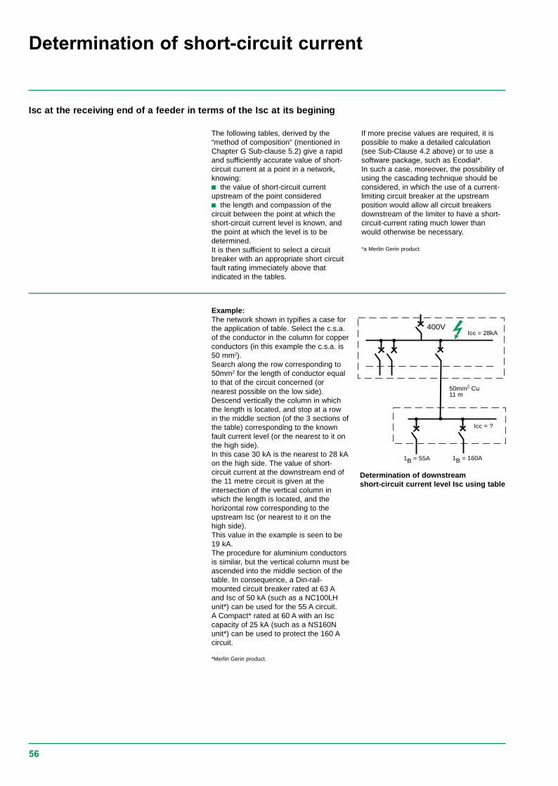
56
Determination of short-circuit current
Isc at the receiving end of a feeder in terms of the Isc at its begining
The following tables, derived by the“method of composition” (mentioned inChapter G Sub-clause 5.2) give a rapidand sufficiently accurate value of short-circuit current at a point in a network,knowing:c the value of short-circuit currentupstream of the point consideredc the length and compassion of thecircuit between the point at which theshort-circuit current level is known, andthe point at which the level is to bedetermined.It is then sufficient to select a circuitbreaker with an appropriate short circuitfault rating immeciately above thatindicated in the tables.
If more precise values are required, it ispossible to make a detailed calculation(see Sub-Clause 4.2 above) or to use asoftware package, such as Ecodial*.In such a case, moreover, the possibility ofusing the cascading technique should beconsidered, in which the use of a current-limiting circuit breaker at the upstreamposition would allow all circuit breakersdownstream of the limiter to have a short-circuit-current rating much lower thanwould otherwise be necessary.
*a Merlin Gerin product.
400VIcc = 28kA
50mm2 Cu11 m
Icc = ?
1B = 55A 1B = 160A
Example:The network shown in typifies a case forthe application of table. Select the c.s.a.of the conductor in the column for copperconductors (in this example the c.s.a. is50 mm2).Search along the row corresponding to50mm2 for the length of conductor equalto that of the circuit concerned (ornearest possible on the low side).Descend vertically the column in whichthe length is located, and stop at a rowin the middle section (of the 3 sections ofthe table) corresponding to the knownfault current level (or the nearest to it onthe high side).In this case 30 kA is the nearest to 28 kAon the high side. The value of short-circuit current at the downstream end ofthe 11 metre circuit is given at theintersection of the vertical column inwhich the length is located, and thehorizontal row corresponding to theupstream Isc (or nearest to it on thehigh side).This value in the example is seen to be19 kA.The procedure for aluminium conductorsis similar, but the vertical column must beascended into the middle section of thetable. In consequence, a Din-rail-mounted circuit breaker rated at 63 Aand Isc of 50 kA (such as a NC100LHunit*) can be used for the 55 A circuit.A Compact* rated at 60 A with an Isccapacity of 25 kA (such as a NS160Nunit*) can be used to protect the 160 Acircuit.
*Merlin Gerin product.
Determination of downstreamshort-circuit current level Isc using table

57
copper c.s.a. of length of circuit (in metres)230V/ phase400V conductors
(in mm2)1.5 0.8 1 1.3 1.6 32.5 1 1.3 1.6 2.1 2.6 54 0.8 1.7 2.1 2.5 3.5 4 8.56 1.3 2.5 3 4 5 6.5 1310 0.8 1.1 2.1 4 5.5 6.5 8.5 11 2116 0.9 1 1.4 1.7 3.5 7 8.5 10 14 17 3425 1 1.3 1.6 2.1 2.6 5 10 13 16 21 26 5035 1.5 1.9 2.2 3 3.5 7.5 15 19 22 30 37 7550 1.1 2.1 2.7 3 4 5.5 11 21 27 32 40 55 11070 1.5 3 3.5 4.5 6 7.5 15 30 37 44 60 75 15095 0.9 1 2 4 5 6 8 10 20 40 50 60 80 100 200120 0.9 1 1.1 1.3 2.5 5 6.5 7.5 10 13 25 50 65 75 100 130 250150 0.8 1 1.1 1.2 1.4 2.7 5.5 7 8 11 14 27 55 70 80 110 140 270185 1 1.1 1.3 1.5 1.6 3 6.5 8 9.5 13 16 32 65 80 95 130 160 320240 1.2 1.4 1.6 1.8 2 4 8 10 12 16 20 40 80 100 120 160 200 400300 1.5 1.7 1.9 2.2 2.4 5 9.5 12 15 19 24 49 95 120 150 190 2402x120 1.5 1.8 2 2.3 2.5 5.1 10 13 15 20 25 50 100 130 150 200 2502x150 1.7 1.9 2.2 2.5 2.8 5.5 11 14 17 22 28 55 110 140 170 220 2802x185 2 2.3 2.6 2.9 3.5 6.5 13 16 20 26 33 65 130 160 200 260 3003x120 2.3 2.7 3 3.5 4 7.5 15 19 23 30 38 75 150 190 230 300 3803x150 2.5 2.9 3.5 3.5 4 8 16 21 25 33 41 80 160 210 250 330 4103x185 2.9 3.5 4 4.5 5 9.5 20 24 29 39 49 95 190 240 290 390Isc upstream Isc downstream(in kA) (in Ka)100 94 94 93 92 91 83 71 67 63 56 50 33 20 17 14 11 9 590 85 85 84 83 83 76 66 62 58 52 47 32 20 16 14 11 9 4.580 76 76 75 75 74 69 61 57 54 49 44 31 19 16 14 11 9 4.570 67 67 66 66 65 61 55 52 49 45 41 29 18 16 14 11 5 4.560 58 58 57 57 57 54 48 46 44 41 38 27 18 15 13 10 8.5 4.550 49 48 48 48 48 46 42 40 39 36 33 25 17 14 13 10 8.5 4.540 39 39 39 39 39 37 35 33 32 30 29 22 15 13 12 9.5 8 4.535 34 34 34 34 34 33 31 30 29 27 26 21 15 13 11 9 8 4.530 30 329 29 29 29 28 27 26 25 24 23 19 14 12 11 9 7.5 4.525 25 25 25 24 24 24 23 22 22 21 20 17 13 11 10 8.5 7 420 20 20 20 20 20 19 19 18 18 17 17 14 11 10 9 7.5 6.5 415 15 15 15 15 15 15 14 14 14 13 13 12 9.5 8.5 8 7 6 410 10 10 10 10 10 10 9.5 9.5 9.5 9.5 9 8.5 7 6.5 6.5 5.5 5 3.57 7 7 7 7 7 7 7 7 6.5 6.5 6.5 6 5.5 5 5 4.5 4 2.95 5 5 5 5 5 5 5 5 5 5 5 4.5 4 4 4 3.5 3.5 2.54 4 4 4 4 4 4 4 4 4 4 4 3.5 3.5 3.5 3 3 2.9 2.93 3 3 3 3 3 3 3 3 2.9 2.9 2.9 2.8 2.7 2.6 2.5 2.4 2.3 1.92 2 2 2 2 2 2 2 2 2 2 1.9 1.9 1.8 1.8 1.7 1.7 1.41 1 1 1 1 1 1 1 1 1 1 1 1 1 1 0.9 0.9 0.9 0.8
aluminium c.s.a of length of circuit (in metres)230 V/ phase400 V conductors
(mm2)2.5 0.8 1 1.3 1.6 34 1 1.3 1.6 2.1 2.6 54 0.8 1.6 2 2.4 3 4 810 1.3 2.6 3.5 4 5.5 6.5 1316 0.8 1.1 2.1 4 5.5 6.5 8.5 11 2125 0.8 1 1.3 1.7 3.5 6.5 8.5 10 13 17 3335 0.9 1.2 1.4 1.8 2.3 4.5 9 12 14 18 23 4650 1.3 1.7 2 2.6 3.5 6.5 13 17 20 26 33 6570 0.9 1.8 2.3 2.8 3.54 4.5 9 18 23 28 37 46 9095 1.3 2.5 3 4 5 6.5 13 25 32 38 50 65 130120 0.8 1.7 3 4 4.5 6.5 8 17 32 40 47 65 80 160150 0.9 1.7 3.5 4.5 5 7 8.5 17 34 43 50 70 85 170185 0.9 1 2 4 5 6 8 10 20 40 50 60 80 100 240240 0.9 1 1.1 1.3 2.5 5 6.5 7.5 10 13 25 50 65 75 100 130 250300 0.9 1 1.2 1.4 1.5 3 6 7.5 9 12 15 30 60 75 90 120 150 3002x120 0.9 1.1 1.3 1.4 1.6 3 6.6 8 9.5 13 16 32 65 80 95 130 160 3202x150 1 1.2 1.4 1.5 1.7 3.5 7 9 10 14 17 35 70 85 100 140 1702x185 1.2 1.4 1.6 1.8 2 4.1 8 10 12 16 20 41 80 100 120 160 2002x240 1.5 1.8 2 2.3 2.5 5 10 13 15 20 25 50 100 130 150 200 2503x120 1.4 1.7 1.9 2.1 2.4 4.5 9.5 12 14 19 24 48 95 120 140 190 2403x150 1.5 1.8 2.1 2.3 2.6 5 10 13 15 21 26 50 100 130 150 210 2603x185 1.8 2.1 2.4 2.7 3 6 12 15 18 24 30 60 120 150 189 240 3003X240 2.3 2.7 3 3.5 4 7.5 15 19 23 30 38 75 150 190 230 300 380
Isc at a point downstream, in terms of a known upstream fault-current value and the length and c.s.a. of the intervening conductors,in a 230/400 V 3-phase system.
note: for a 3-phase system having 230 V between phases, divide the above lengths by 3 = 1.732
Isc at the receiving end of a feeder in terms of the Isc at its sending end (continued)

58
Selecting circuit breakers supplied by one or moreMV/LV transformers
maximum short-circuitcurrent downstream ofan MV/LV transformer
The values indicated in the table belowcorrespond to a bolted 3-phase short-circuitaccross the LV terminals of an MV/LVtransformer connected to a network witha short-circuit power of of 500MVA.
transformer kVA rating
16 25 40 50 63 80 100 125 160 200 250 315 400 500 630 800 1000 1250 1600 2000415vIn (A) 22 53 56 70 88 112 140 174 223 278 348 438 556 696 877 1113 1391 1740 2226 2783Isc (A) 450 700 1120 1390 1760 2230 2790 3490 4460 5580 6970 8790 11160 12950 17570 22320 27890 33120 38540 48180Impedence 4.75 4.75 4.75 4.75 4.75 4.75 4.75 4.75 4.75 4.75 4.75 4.75 4.75 4.75 4.75 4.75 4.75 5 5.5 5.5usual (%)
selecting incoming oroutgoing circuit breakersaccording to the numberand kVA rating of sourcetransformers
The selection of a circuit breakerprotecting a circuit mainly depends on:c the rated current of the source or ofthe load which determines the rating ofthe equipment.c the maximum short-circuit current atthe point of installation which determinesthe minimum breaking capacity of theequipment.
Case with several transformers
For the case involving severaltransformers in parallel(1):in the incoming circuit breaker D1 musthave a breaking capacity higher than thelarger of the following 2 values:v either Isc1 (for a short-circuit in B1)
v or Isc2 + Isc3 (for a short-circuit in A1)
c the outgoing circuit breaker D4 musthave a breaking capacity higher than Isc1+ Isc2 + Isc3.
See page 91
HV HV HV
1
LVA1
D1B1
Isc1
D4C
2
LVA2
D2B2
Isc2
D5
3
LVA3
D3B3
Isc3

59
Energy let - through
Current limiting curves The current limiting capacity of a circuitbreaker is expressed by two curves whichgive, as a function of the prospective short-circuit current (the current which would flowif no protection devices were installed):
c The actual peak current (limited current);c The thermal stress (A2s), i. e. the energydissipated by the short-circuit in a conductorwith a resistance of 1 Ω.
Is an Cu/PVC cable with a cross-section of10 mm2 adequately protected by anNS160N?
Answer:The table below indicates that thepermissible stress is 1.32 106 A2s.All short-circuit currents at the point wherean NS160N (Icu = 35 kA) is installed arelimited with a thermal stress less than6 105 A2s.Cable protection is therefore ensured up tothe limit of the breaking capacity of thecircuit breaker.
2 3 4 6 10 20 30 40 60 100 200 300
A S2
2
3
5
2
3
5
2
3
5
2
105
106
107
NS250NS160NS100
3
5
108
H
C801LC1001L
C801NC1001NC1251N
C801HC1001HC1251H
kA rms
NS630
NS400
N H
N H
L
L
N
2
3
5
109
N
L
L
50mm2
35mm2
25mm2
16mm2
10mm2
4mm2
2.5mm2
1.5mm2
cablecrosssectionguide
6mm2
NS80 HMA
0.2
A S2
104
105
106
107
kA rms
50mm2
35mm2
25mm2
16mm2
10mm2
4mm2
2.5mm2
1.5mm2
1.5 0.5 0.8 1. 1.5 2 3 4 5 6 7 8 10
3
5
2
3
5
2
3
5
2
10
10
10
3
5
10
2
< 63A
< 40A
< 10A
< 6A
< 40A
12
cablecrosssectionguide
1 - C60X 2 - C60H
6mm2
Thermal Stress Limitation Thermal Stress Limitation

60
Earth loop impedance values
Circuit Max. ZsBreaker Ohms @
230 Volts
Type Trip 0.4 5secs secs
NS10025kA TM16G 2.99 2.99
TM25G 2.40 2.40TM40G 2.40 2.40TM63G 1.83 1.83
NS100TM16D 0.96 1.64TM25D 0.62 1.28TM32D 0.60 0.80TM40D 0.38 0.77TM50D 0.38 0.58TM63D 0.38 0.51TM80D 0.29 0.29TM100D 0.18 0.18
NS160TM80D 0.23 0.23TM100D 0.18 0.18TM125D 0.18 0.18TM160D 0.15 0.15
NS250TM200D 0.08 0.08TM250D 0.08 0.08
NS100STR22SE 25A 0.80 1.15
40A 2.50 0.7263A 0.32 0.46100A 0.20 0.29
NS160STR22SE 100A 1.59 0.29
160A 1.00 0.18
NS250STR22SE 160A 0.13 0.18
250A 0.08 0.12
NS400STR23SE 400A 0.05 0.07STR53SE 400A 0.05 0.52
NS630STR23SE 630A 0.05 0.07STR53UE 630A 0.05 0.52
C801 800A 0.03 0.04C1001 1000A 0.02 0.03C1251 1250 0.02 0.02
Circuit Max. ZsBreaker Ohms @
230 Volts
Type Trip 0.4 5secs secs
MA Trip units
NS80HMAX MA1.5 9.13 9.13
MA2.5 5.48 5.48MA6.3 2.17 2.17MA12.5 1.10 1.10MA25 0.55 0.55MA50 0.27 0.27MA80 0.17 0.17
NS100MAX MA2.5 5.48 9.13
MA6.3 2.17 2.17MA12.5 1.10 1.10MA25 0.55 0.55MA50 0.27 0.27MA100 0.14 0.14
NS160MAX MA150 0.09 0.09
NS250MAX MA220 0.05 0.05
NS400MAX MA320 0.04 0.04
NS630MAX MA500 0.03 0.03
Minipact16A 0.32 2.7420A 0.32 2.4025A 0.32 2.4032A 0.32 1.2840A 0.32 1.0150A 0.19 0.7760A 0.19 0.64
Circuit Max. ZsBreaker Ohms @
230 Volts
Type Trip 0.4 5secs secs
C60type B 1A 46.00 46.00
2A 23.00 23.003A 11.50 11.506A 7.67 7.6710A 4.60 4.6016A 2.88 2.8820A 2.30 2.3025A 1.84 1.8432A 1.44 1.4440A 1.15 1.1550A 0.92 0.9263A 0.73 0.73
C60type C 1A 23.00 29.49
2A 11.50 14.383A 5.75 7.426A 3.88 4.8910A 2.30 2.9516A 1.44 1.8420A 1.15 1.4725A 0.92 1.1832A 0.72 0.9240A 0.58 0.7450A 0.46 0.5963A 0.37 0.47
C60type D 1A 16.43 29.49
2A 8.21 14.383A 4.11 7.426A 2,74 4.8910A 1.64 2.9516A 1.03 1.8420A 0.82 1.4725A 0.66 1.1832A 0.51 0.9240A 0.41 0.7450A 0.33 0.5963A 0.26 0.47
Circuit Max. ZsBreaker Ohms @
230 Volts
Type Trip 0.4 5secs secs
C120Htype B 10A 4.60 4.60
16A 2.88 2.8820A 2.30 2.3025A 1.84 1.8432A 1.44 1.4440A 1.15 1.1550A 0.92 0.9263A 0.73 0.7380A 0.57 0.57100A 0.46 0.46125A 0.36 0.36
C120Htype C 10A 2.30 2.87
16A 1.44 1.7920A 1.15 1.4425A 0.92 1.1532A 0.72 0.9040A 0.58 0.7150A 0.46 0.5763A 0.37 0.4580A 0.29 0.35100A 0.23 0.28125A 0.18 0.23
C120Htype D 10A 1.64 2.87
16A 1.03 1.7920A 0.82 1.4425A 0.66 1.1532A 0.51 0.9040A 0.41 0.7150A 0.33 0.5763A 0.26 0.4580A 0.21 0.35100A 0.16 0.28125A 0.13 0.23
Zs values are given with circuit breakers set at maximum

61
Inrush currents When LV/LV transformers are switched on,very high inrush currents are produced whichmust be taken into account when choosingovercurrent protection devices.
The peak value of the first current waveoften reaches 10 to 15 times the rated rmscurrent of the transformer and may reachvalues of 20 to 25 times the rated currenteven for transformers rated less than50 kVA.This transient inrush current decays veryquickly (in a few milliseconds).
Î 1ere crête10 à 25In
In
θ
I
t
Selecting the protection Merlin Gerin has conducted an extensivetest programme to optimise the protection ofLV/LV transformers.The Compact and Masterpact circuitbreakers detailed in the following tables offerthe following advantages:c Protection of the transformer in the eventof abnormal overloads;c No nuisance tripping when the primarywinding is energised;c Unimpaired electrical endurance of thecircuit breaker.
The transformers used for the tests arestandard. The values in the tables have beencalculated for a crest factor of 25. Thesetables indicated the circuit breaker and tripunit to be used depending on:c The primary supply voltage (230 V or400 V) ;c The type of transformer (single-phase orthree-phase).They correspond to the most frequent casein which the primary is wound externally(1).The type of circuit breaker to be used (i.e. N,H or L) depends on the breaking capacityrequired at the point of installation.
epprimary winding
Protection of LV/LV transformers

62
Protection usingCompact circuitbreakers
(1) For other windings, please consult us.If a circuit breaker upstream of a transformer witha transformation ratio of 1 and a rated power ofless than 5 kVA is subject to nuisance tripping,before choosing a circuit breaker with a higherrating, invert the input and the output of thetransformer (the inrush current may be doubled ifthe primary is wound internally rather thanexternally).
Compact NS100 to NS250 equipped with TM-D thermal-magnetic trip unitTransformer rating (kVA) Protective device230 V 1-ph 230 V 3-ph/ 400 V 3-ph Circuit breaker Trip unit
400 V 1-ph3 5 to 6 9 to 10 NS100N/H/L TM16D5 8 to 9 14 to 16 NS100N/H/L TM25D7 to 9 13 to 16 22 to 28 NS100N/H/L TM40D12 to 15 20 to 25 35 to 44 NS100N/H/L TM63D16 to 19 26 to 32 45 to 56 NS100N/H/L TM80D18 to 23 32 to 40 55 to 69 NS160N/H/L TM100D23 to 29 40 to 50 69 to 87 NS160N/H/L TM125D29 to 37 51 to 64 89 to 111 NS250N/H/L TM160D37 to 46 64 to 80 111 to 139 NS250N/H/L TM200D
Compact NS100 to C1251 equipped with STR electronic trip unitTransformer rating (kVA) Protective device230 V 1-ph 230 V 3-ph/ 400 V 3-ph Circuit breaker trip unit Ir max setting
400 V 1-ph4 to 7 6 to 13 11 to 22 NS100N/HL STR22SE 40 0.89 to 19 16 to 32 27 to 56 NS100N/H/L STR22SE 100 0.815 to 30 25 to 52 44 to 90 NS160N/H/L STR22SE 160 0.823 to 46 40 to 80 70 to 139 NS250N/H/L STR22SE 250 0.837 to 74 64 to 128 111 to 222 NS400N/H/L STR23SE 400 0.858 to 115 100 to 200 175 to 346 NS630N/H/L STR23SE 630 0.874 to 184 127 to 319 222 to 554 C801N/H STR35SE 800 192 to 230 159 to 398 277 to 693 C1001N/H STR35SE 1000 1115 to 288 200 to 498 346 to 866 C1251N/H STR35SE 1250 1
Protection of LV/LV transformers
AssumptionsThe tables give recommended mcb ratingsfor single phase transformers up to 12500VA and three phase transformers up to30000 VA based on the following formula:
MCB rating =15 x normal running current of transformermin. instantaneous trippingcoefficient of mcb
Table 3 - 3 phase transformers 415V AC supplyVA Primary In (A) C60HB C60HC C60HD NC100C NC100D500 0.7 4 2 1 - -750 1.04 6 4 2 - -1000 1.39 10 6 4 - -2000 2.78 16 10 6 10 -5000 6.95 40 25 16 25 1610000 13.89 - 50 25 50 2515000 20.84 - 63 32 63 3220000 27.78 - - 50 63 5025000 34.73 - - 63 80 6330000 41.67 - - 63 100 63
Table 4 - 1 phase transformers 240V AC supplyVA Primary In (A) C60HB C60HC C60HD NC100C NC100D50 0.21 2 - - - -100 0.42 4 2 1 - -250 1.04 6 4 2 - -500 2.08 16 …10 4 - -1000 4.17 25 16 10 10 102500 10.42 63 32 16 25 165000 20.84 - 63 32 50 3210000 52.08 - - 63 80 6312500 52.08 - - - 100 80

63
400 HZ applications
Adaptation coefficientsCompact Trip unit Rating Long-time Short-time K2Circuit Ir at 50 Hz Ir maxi Irm at 50 Hz
breaker (A at 40 °C) K1 (A)
NS100N STR22SE 40...100 0.4 to 1 2 to 10 Ir 1NS250N STR22SE 100...250 0.4 to 0.9 2 to 10 Ir 1NS400N STR23SE 400 0.4 to 0.8 1.5 to 10 Ir 1NS630N STR23SE 630 0.4 to 0.8 1.5 to 10 Ir 1NS400N STR53UE 400 0.4 to 0.8 1.5 to 10 Ir 1NS630N STR53UE 630 0.4 to 0.8 1.5 to 10 Ir 1C801N STR25DE 800 0.4 to 0.75 1.5 to 10 Ir 0.97
STR35SE/GE 800 0.4 to 0.75 1.5 to 10 Ir 0.97C1001N STR25DE 1000 0.4 to 0.75 1.5 to 10 Ir 0.97
STR35SE/GE 1000 0.4 to 0.75 1.5 to 10 Ir 0.97C1251N STR25DE 1250 0.4 to 0.75 1.5 to 10 Ir 0.97
STR35SE/GE 1250 0.4 to 0.75 1.5 to 10 Ir 0.97
Circuit Trip unit Thermal setting K1 Magnetic K2breaker at 40 °C settingNS100N TM16G 16 0.95 63 1.6
TM25G 25 0.95 80 1.6TM40G 40 0.95 80 1.6TM63G 63 0.95 125 1.6
NS250N TM16D 16 0.95 240 1.6TM25D 25 0.95 300 1.6TM40D 40 0.95 500 1.6TM63D 63 0.95 500 1.6TM80D 80 0.9 650 1.6TM100D 100 0.9 800 1.6TM125D 125 0.9 1000 1.6TM160D 160 0.9 1250 1.6TM200D 200 0.9 1000 (*) 1.6TM250D 250 0.9 1250 (*) 1.6
(*) for TM 200D and TM250D, Im must be set to its maximum
Tripping thresholdsThe 400 Hz current settings are obtained bymultiplying the 50 Hz values by the followingcoefficient:
c K1 for thermal trip units;
c K2 for magnetic trip units.
On adjustable trip units, these adaptationcoefficients are independent of the unitadjustment knob position.
Electronic trip units
The use of electronics offers the advantageof greater operating stability when thefrequency is varied. However, the devicesare still subjected to frequency relatedtemperature effects which may sometimespose restrictions on their use.
Column K1 of the table below gives themaximum permissible current to be used forthe current setting (knob position).
For thermal trip units, the current settingsare lower at 400 Hz than at 50 Hz (K1 i 1).
For magnetic trip units, the current settingsare conversely higher at 400 Hz than at50 Hz (K2 u 1).
Adjustable trip units should be set tominimum, or use Compact circuit breakersequipped with low magnetic trip units(type G).
Electronic trip units
Thermal-magnetic trip units

64
Breaking capacity of Compact NS andCompact C circuit breakers at 400 HzAt 440 V, 400 Hz:
Circuit breaker Breaking capacity
NS100N 12 kANS250N 4,5 kANS400N 10 kANS630N 10 kAC801N 25 kAC1001N 25 kAC1251N 25 kA
auxiliary releasesFor Compact NS100-630
For circuit breakers on 400 Hz systems, only125 V DC rated releases can be used. Therelease must be supplied by the 400 Hzsystem via a rectifier bridge (to be selectedfrom the table opposite) and an additionalresistor with characteristics depending onthe system voltage and the type of circuitbreaker.
For Compact C801-1251
The following auxiliary releases are designedto operate at 400 Hz.
U (V) 400 Hz Rectifier Additional resistor110/127 V Thomson 110 BHz or 10 kΩ-2 W
General Instrument W06 orSemikron SKB at 1,2/1,3
220/240 V Thomson 110 BHz or 22 kΩ-8 WGeneral Instrument W06 orSemikron SKB at 1,2/1,3
380/420 V Semikron SKB at 1,2/1,3 33 kΩ-15 W
Note : other models of rectifier bridges can be used iftheir characteristics are at least equivalent to those statedabove.
U (V) 400 Hz Catalogue number
MN 110/130 V 44925MN 208/250 V 44926MN 380/415 V 44932MX 380/415 V 44914

65
Circuit breaker selection for DC applications
Type of system Earthed systems Insulated systemsOne polarity of the DC supply is A centre point of the DC supply isearthed earthed
Diagramsand variouscases of faults
Fault effect Fault A Max. Isc Isc close to max. Isc No effectthe positive polarity the positive polarity is the onlyis the only one involved one involved, voltage U/2
Fault B Max. Isc Max. Isc Max. Iscboth polarities are involved both polarities are involved both polarities are involved
Fault C No effect Same as fault A but this is the No effectnegative polarity which is involved
Most unfavorable case Fault A Faults A and C Fault BDistribution of the The poles required to perform On each polarity there must be the the poles required to performbreaking poles the break are in series number of poles required to perform the break are shared between
on the positive polarity the break of max. Isc at U/2 the 2 polarities
Selection criteriaThe selection of the type of circuit breakermost suitable for protection of aDC installation depends mainly on thefollowing criteria:
c The rated current, which determines therating of the equipment;
c The rated voltage, which determines thenumber of poles in series necessary forbreaking;
c The maximum short-circuit current at thepoint of installation, which determines thebreaking capacity;
c The type of network (see below).
Calculation the short-circuit current (Isc)across the terminals of a battery
When a short-circuit occurs across itsterminals, a battery discharges a currentgiven by Ohm's law:
Where Vb = the maximum discharge voltage(battery 100 % charged).
and Ri = the internal resistance equivalent tothe sum of the cell resistances (figuregenerally given by the manufactureraccording to the capacity of the battery).
Example
What is the short-circuit current at theterminals of a standing battery with thefollowing characteristics:
c Capacity: 500 Ah;
c Max. discharge voltage: 240 V(110 cells of 2.2 V);
c Discharge current: 300 A;
c Autonomy: 1/2 hour;
c Internal resistance: 0.5 mΩ per cell.
Ri = 110 x 0.5 10-3 = 55 x10-3
As the above calculation shows, the short-circuit current is relatively weak.
Note: If the internal resistance is not known, the followingapproximate formula can be used: Isc = kC, where C is thecapacity of the battery expressed in Ampere-hours, and kis a coefficient close to 10 but in any case always lowerthan 20.
Example 1
Determine the protection required for a 80 Afeeder on a 125 V DC network with anearthed negative pole and an Isc of 15 kA.
Example 2
Determine the protection required for a100 A feeder on a 250 V DC network with anearthed middle point and an Isc of 15 kA.
Example 3
Determine the protection required for a400 A feeder on an unearthed 250 V DCnetwork with an Isc of 35 kA.
The table opposite indicates that a NC100Hcircuit breaker (30 kA, 2P, 125 V) should beused.
The table above indicates that both circuitbreaker poles should be fitted on the positivepole of the network.
An additional circuit breaker pole can befitted on the negative pole of the network forisolation purposes.
Each pole will be exposed to a maximum ofU/2 = 125 V.
The table opposite indicates that NC100H(30 kA, 2P, 125 V), NS100N (50 kA, 1P,125 V) or NS160N (50 kA, 1P, 125 V) circuitbreakers should be used.
The table above indicates that both circuitbreaker poles must take part in the breakingat a voltage of 125 V.
The table opposite indicates that NS400Hcircuit breakers (85 kA, 1P, 250 V) should beused. At least 2 poles must take part inbreaking. The table above indicates that thehalf the number of circuit breaker polesrequired for breaking should be fitted on thepositive pole of the network and the otherhalf on the negative pole.
Isc = VbRi
Isc = = 4.4kA 24055 10-3

66
Type Rated current (A) Breaking capacity (kA) (L/R iiiii 0.015 s) Protection against Protection againstand (and number of poles required to perform the break) overloads (thermal) short-circuits (mag)
trip units 24/48 V 125 V 250 V 500 V 750 V
NS100N 16-25-40-63-80-100 50(1p) 50 (1p) 50 (1p) 50 (2p) Same as for trip unitsNS100H 16-25-40-63-80-100 85 (1p) 85 (1p) 85 (1p) 85 (2p) used on AC systemsNS100L 16-25-40-63-80-100 100 (1p) 100 (1p) 100 (1p) 100 (2p)NS160N 80-100-125-160 50 (1p) 50 (1p) 50 (1p) 50 (2p)NS160H 80-100-125-160 85 (1p) 85 (1p) 85 (1p) 85 (2p)NS160L 80-100-125-160 100 (1p) 100 (1p) 100 (1p) 100 (2p)NS250N 160-200-250 50 (1p) 50 (1p) 50 (1p) 50 (2p)NS250H 160-200-250 85 (1p) 85 (1p) 85 (1p) 85 (2p)NS250L 160-200-250 100 (1p) 100 (1p) 100 (1p) 100 (2p)NS400H MP1/MP2/MP3 85 (1p) 85 (1p) 85 (1p) 85 (2p) No thermal protection: Specially designed
for DCNS630H MP1/MP2/MP3 85 (1p) 85 (1p) 85 (1p) 85 (2p) An external relayC1251N-DC P21/P41-1250 50 (1p) 50 (1p) 50 (2p) 50 (3p) 25 (3p) must be provided
Selection table of DC circuit breakers
Breaking capacity of miniature circuit-breakers on d.c.(in brackets, the number of poles involved in breaking)type of D.C. breaking capacity(kA)-L/R < 0.015s (IEC 947-2 ,lcu)circuit breaker voltage 24/48V 125V 250V 500VC60HB/HC 20 (1p) 25 (2p) 50 (4p) -C60HD 20 (1p) 25 (2p) 50 (4p) -NC100(10-63A) 36 (1p) 40 (2p) 36 (3p) 36 (3)NC100(80+100A) 20 (1p) 30 (1p) 36 (1p) -

67
Circuit breaker marking- Industrial
TropicalisationCircuit breakers comply with the followingstandards:
c IEC 68-2-30 damp heat;c IEC 68-2-2 dry heat;c IEC 68-2-11 salt spray;c IEC 68-2-1 low temperatures.
Environmental protectionCircuit breakers take intoaccount currentconcerns for environmental protection. Mostcomponents are recyclable and parts aremarked as specified in applicable standards.
Ambient temperaturec Circuit breakers can be used attemperatures ranging from -25°C to 70°C.Above 40°C (or 65°C for circuit breakersused to protect motor feeders), always takeinto account the derating coefficientsindicated in the documentation;
c Wherever possible the circuit breakersshould be put into service at their normalambient operating temperature, however thiscan be done at temperatures between -35°Cand -25°C as long as this condition does notlast for an extended period;
c In their original pack, circuit breakers maybe stored at temperatures ranging from -50°to +85°C.
Conformity with standards Circuit breakers and auxiliaries comply withthe following international recommendations:
c BSEN60 947-1: general rules;
c BSEN60 947-2: circuit breakers;
c BSEN60 947-3: switches, disconnectors,switch-disconnectors, etc;c BSEN60 947-4: contactors and motorsstarters
c BSEN60 947-5.1 and following - controlcircuit devices and switching elements;automatic control components.In that these recommendations are appliedin most countries, Compact circuit breakersand auxiliaries comply with European(EN 60947-1 and EN 60947-2) and thecorresponding national standards:c France NF;c Germany VDE;c U.K BS;c Austrialia AS;c Italy CEI.
They also comply with the specifications ofthe marine classification companies (Veritas,Lloyd’s Register of Shipping, Det NorskeVeritas, etc).
Concerning the United States UL, CanadianCSA, Mexican NOM and Japanese JISstandards, please consult us.
pollution degreeCircuit breakers are certified for operation inpollution-degree III environments as definedby IEC standard 947 (industrialenvironments).
Standardised characteristics indicatedon the rating plate
Ui: rated insulation voltage
Uimp: rated impulse withstand voltage
Icu: ultimate breaking capacity, for variousvalues of the rated operational voltage Ue
cat: utilisation category
Icw: short-time withstand current
Ics: service breaking capacity
In: rated current
: suitable for isolation
MER LIN GERINcompactNS160 HUi 750V. Uimp 8kV.Ue(V)220/240380/415440500/525660/690250
Icu(kA)1007065501085
cat AIcs = 100% Icu
IEC 947.2UTE VDE BS CEI UNE NEMA

68
All Circuit breakers are suitable for isolationas defined in IEC standard 947-2/BS60947-2:
c The isolation position corresponds to theO (OFF position);c The operating handle cannot indicate
the ‘off’ position unless the contacts areeffectively open;c Padlocks may not be installed unless thecontacts are open.
Installation of a rotary handle or a motormechanism does not alter the reliabilitythe position indication system.
The isolation function is certified by tests
which guarantee:c The mechanical reliability of the positionindication system;c The absence of leakage currents;c Overvoltage withstand capacity betweenupstream and downstream connections.
Suitability for isolationpositive contact indication

69
Residual current earth fault protection
RCD Type Rated Current Rated AC Voltage Number of Poles Sensitivity Time DelayAdded to McbC60H Vigi 1-63A 115-264V 1-2 0.03-0.3A N/A
C60H Vigi 1-63A 220-456V 2-4 0.03-0.3A N/A
NC100 Vigi 10-100A 115-264V 1-2 0.03-0.3A 50 to 70 mS
NC100 Vigi 10-100A 220-456V 2-4 0.03-0.3A 50 to 70 mS
C60X Sp Rcbo 6-45A 110-264V 1 0.03A N/A
SPNX Sp + N 6-40A 110-264V 2 0.03 N/A
C60H Sp Rcbo 6-45A 110-264V 1 0.03A N/A
DPN Vigi 6-40A 104-264V 2 0.03A N/A
C120H Vigi 10-125A 230V-415V 2 .03-1A N/A
C120H Vigi 10-125A 230V-415V 3 .03-1A N/A
C120H Vigi 10-125A 230V-415V 4 .03-1A N/A
NG125N Vigi 10-125A 110V-220V 2 .3-1A N/A
NG125N Vigi 10-125A 415V-440V 3 .3-3A N/A
NG125N Vigi 10-125A 110V-220V 4 .3-3A N/A
Added to MCCBNS100-250 Vigi 16-250A 200-440V 3-4 0.03-10A 0-310mS
NS100-250 Vigi 16-250A 440-550V 3-4 0.03-10A 0-310mS
NS400-630 Vigi 400-630A 200-440V 3-4 .03-30A 0-310mS
Incorporated in MCCBNS400-630 Option T 400-630A 690V Max 3-4 .2-1 x In 0-0.4S
C801-C1251 Option T 800-1250A 690V Max 3-4 0.2-0.6 x In 0-0.4S
Incorporated in ACB (NW)Micrologic 600-6300A 220-690V 3-4 120-1200A 0.1-0.4S
Separate RelayRH10E N/A* 1000V 1-4 0.03-.3A N/A
RH240E N/A* 1000V 1-4 0.03-25A 0-1S
RH248E N/A* 1000V 1-4 0.03-25A 0-1S
RH10A N/A* 1000V 1-4 0.03-.3A N/A
RH10AP N/A* 1000V 1-4 0.3-1A 200mS
RH320A N/A* 1000V 1-4 0.03-250A N/A
RH320AP N/A* 1000V 1-4 0.03-250A 0-1S
RH328A N/A* 1000V 1-4 0.03-250A 0-1S
RH328AP N/A* 1000V 1-4 0.03-250A 0-1S
RCCBRMG16-100 16-100A 115-264V 2 0.03-0.3A 50-70mS
RMG25-100 25-100A 115-456V 4 0.03-0.3A 50-70mS
*Separate Toriod CT used.
Refer to relevant product catalogue for details.
Rcd selection

70
Use of LV switches
Functions performed by switch

71
Use of LV switches
The switch is essentially a control device, (generally manual, possibly electrical onopening - termed a free tripping switch) capable of breaking and closing a normalservice circuit. It does not use any electricity to remain open or closed (2 stablepositions).
For safety reasons, in the majority of cases is suitable for isolation.
It must always be used in association with a device which protects againstoverloads and short-circuits.
6 applications have thus been identified:c coupling and insolating switch in a power switchboardc isolating switch in an industrial switchboard and automation cabinetsc isolating switch in a modular switchboardc isolating switch in proximity unitsc isolating switch in small commercial distribution unitsc automation unit switch.
Suitable for isolation
Switch-disconnectorIsolation permits a circuit or a device to be disconnected from the rest of theelectrical installation, in order to guarantee the safety of those who have to achieverepairs or maintenance.
Normally, all circuits in an electrical installation must be capable of being isolated.In practice, to ensure optimal continuity of service, an isolating device is installed atthe start of every circuit distribution.
Certain switches allow this function to be achieved in addition to their circuit controlfunction.
Therefore a switch-disconnector must display the symbol (illustrated opposite),visibly on the front face of the installed device.
Isolating functionInstallation standards stipulate the requirements which must be respected in orderfor a device to carry out its isolating function.
It must:c be with equipped with omnipolar isolation, that is to say that the live conductors,including the neutral (with the exception of the PEN conductor which must never beisolated) must be isolated simultaneouslyc be lockable in the “open” position so as to prevent any risk of involontaryreclosing ; this is imperative for industrial devicesc conform to a standard which guarantees its suitability for isolationc It must also meet overvoltage withstand requirements. However, if the isolation isexplicitly recognized by a manufacturing standard, for example IEC 60947-1/3 forindustrial switch-disconnectors, a device which complies with this isolationstandard is judged to comply fully with the conditions required by installationstandards.
The manufacturing standard guarantees its use for isolation suitability for the user.
Functions and positions of LV switches
MER LIN GERIN
. Ui 750V .
INS160
Uimp 8kVLth 100A 60 C
Ue(V) Ie100A100A
interpact
IEC 947.3 E VDE BS CEI UNE

72
Use of LV switches (cont)
Switch standards and characteristics
Switch standardsStandards define:c the frequency of operation cycles (with a maximum of 120 per hour)c mechanical and electrical endurancec operating breaking and making capacityv normalv occasional (closing on short-circuit for example)c utilization categories.
The IEC standards 60947-3 (1) and 60669-1 (2) thus define the principal valueswhich are given below.
Utilization categoryDepending on the rated operating current and the A or B mechanical endurance,standards define the utilization categories shown in the table below.
Example:A switch with a rating of 125 A, from the AC23 category must be able to:c make a 10 In (1250 A) current with a cos ϕ of 0.35c break a 8 In (1000 A) current with a cos ϕ of 0.35.
Its other characteristics are:c to withstand a 12 In - 1 s short-circuit current, which defines the Icw = 1500 Ar.m.s. thermal withstand during 1 sc Icm (peak A) short-circuit making capacity which corresponds to theelectrodynamic loads.
Utilization category Characteristic applications
Frequent Non frequentoperations operations
AC-21A AC-21B Resistive loads includingmoderate overloads (cos ϕ = 0,95)
AC-22A AC-22B Mixed resistive and inductive loads includingmoderate overloads (cos ϕ = 0,65)
AC-23A AC-23B Motors with cage winding or orther loadswhich are very inductive (cos ϕ = 0,45 or 0,35)
(1) The industrial type of switch is defined by the IEC standard 60947-3.(2) The domestic type of switch is defined by the IEC standard 60669-1.
Choice of switch criteria
Network characteristicsNominal voltage, nominal frequency and nominal current are determined in the sameway as they are for a circuit breaker:c nominal voltage = network nominal voltagec frequency = network frequencyc nominal current = rated current with a value which is just above the downstreamload current. It is to be noted that the rated current is defined for a given ambienttemperature and that a derating may possibly have to be taken into account.
Localization and applicationThis determines the type and characteristics or major functions that the switchshould include. There are 3 levels of functions (see the table opposite):
c basic functionspractically common to all types of switch: isolation, control, notice.
c functions with complementary characteristics.
They are the direct translation of the user’s needs and the environment in which theswitch is located.

73
Use of LV switches (cont)
These are:v industrial type performancesv Isc levelv type of lockingv type of controlv utilization categoryv mounting system.
c specific functionsThey are linked to the operation and installation restrictions, which are:v earth leakage protectionv electrical controlsv remote openingv withdrawable capacity.
Circuit-breaker or fuse / switchcoordination
CoordinationAs a switch only has a limited breaking capacity and short-circuit withstand, it mustbe protected by a short-circuit protection device (SCPD) placed upstream.
Tables show the SCPD (circuit-breaker or fuse) ensuring proper coordination withthe switches in the event of a downstream short-circuit.
Warning: switches must be also protected against overloads. It's generallyadmitted that the protection against the overloads and short-circuit, is ensured byeach downstream circuit-breakers as these circuit-breakers and these switches arelocated in the same switchboard, designed according to the electrical standards.
Modular switchExample 1:An enclosure feeder, with an Isc on the busbar of 20 kA, supplies loads withoperational currents of 30 A, 20 A and 10 A respectiveldy in single-phase. Theinstallation earthing system is the TT one. The feeder supplying this enclosure isplaced in the upstream switchboard and protected by a two-pole NC100H circuit-breaker. Which residual current switch should you choose for the enclosureincomer?As the feeders are placed in the same enclosure as the switch, cordination can beachieved with each enclosure feeder. Choice will thus be made of an RMG residualcurrent switch of rating 63 A and of C60H type circuit-breakes for the feeders: thetable above shows that the C60H withstands 20 kA in this case.
C60H30 A
C60H30 A
C60H30 A
NC100H
Icc 20 kA

74
Switch-disconnectors protection
Compact switch-disconnectors NS400NA NSUpstream protectionBy circuit breaker type / maximum rating (A) NS400-630N / 400 NS6
Isc max. (380/415 V) kA rms 45 45making capacity (380/415 V) kA peak 94 94type / maximum rating (A) NS400-630H / 400 NS6Isc max. (380/415 V) kA rms 70 70making capacity (380/415 V) kA peak 154 154type / maximum rating (A) NS400-630L / 400 NS6Isc max. (380/415 V) kA rms 150 150making capacity (380/415 V) kA peak 330 330type / maximum rating (A)Isc max. (380/415 V) kA rmsmaking capacity (380/415 V) kA peaktype / maximum rating (A)Isc max. (380/415 V) kA rmsmaking capacity (380/415 V) kA peak
By fuse type aM (1) maximum rating (A) 400 500Isc max. (500 V) kA rms 100 100making capacity (500 V) kA peak 220 220type gl (2) maximum rating (A) 315 500Isc max. (500 V) kA rms 100 100making capacity (500 V) kA peak 220 220type gl (1) maximum rating (A) 400 630Isc max. (500 V) kA rms 100 100making capacity (500 V) kA peak 220 220type BS (2) maximum rating (A) 315 & 200M315 450Isc max. (500 V) kA rms 80 80making capacity (500 V) kA peak 176 176type BS (1) maximum rating (A) 355 & 315M355 500Isc max. (500 V) kA rms 80 80making capacity (500 V) kA peak 176 176
Compact switch-disconnectors NS100NA NSUpstream protectionBy circuit breaker type / maximum rating (A) NS100N / 100 NS1
Isc max. (380/415 V) kA rms 25 36making capacity (380/415 V) kA peak 52 75type / maximum rating (A) NS160-250N / 100 NS1Isc max. (380/415 V) kA rms 36 70making capacity (380/415 V) kA peak 75 154type / maximum rating (A) NS100-250H / 100 NS1Isc max. (380/415 V) kA rms 70 150making capacity (380/415 V) kA peak 154 330type / maximum rating (A) NS100-250L / 100 NSAIsc max. (380/415 V) kA rms 150 30making capacity (380/415 V) kA peak 330 63type / maximum rating (A) NSA160N / 100Isc max. (380/415 V) kA rms 30making capacity (380/415 V) kA peak 63
By fuse type aM (1) maximum rating (A) 100 160Isc max. (500 V) kA rms 80 33making capacity (500 V) kA peak 176 69type gl (2) maximum rating (A) 80 125Isc max. (500 V) kA rms 100 100making capacity (500 V) kA peak 220 220type gl (1) maximum rating (A) 160 160Isc max. (500 V) kA rms 100 100making capacity (500 V) kA peak 220 220type BS (2) maximum rating (A) 80 & 63M80 125Isc max. (500 V) kA rms 80 80making capacity (500 V) kA peak 176 176type BS (1) maximum rating (A) 160 & 100M160 160Isc max. (500 V) kA rms 80 80
pushto
trip
pushto
trip
(1) Protection by external thermal relay obligatory.(2) Without external thermal relay.

75
NS400NA NS630NA C801NI C1251NI
NS400-630N / 400 NS630N / 630 C801-1251N / 800 C1251N / 1250kA rms 45 45 50 50kA peak 94 94 105 105
NS400-630H / 400 NS630H / 630 C801-1251H / 800 C1251H / 1250kA rms 70 70 70 70kA peak 154 154 154 154
NS400-630L / 400 NS630L / 630 C801-1001L / 800 C1001L/1000kA rms 150 150 150 150kA peak 330 330 330 330
kA rmskA peak
kA rmskA peak
400 500 630 1000kA rms 100 100 100 100kA peak 220 220 220 220
315 500 630 1000kA rms 100 100 100 100kA peak 220 220 220 220
400 630 800 1250kA rms 100 100 100 100kA peak 220 220 220 220
315 & 200M315 450 & 400M450 630 1000kA rms 80 80 80 80kA peak 176 176 176 176
355 & 315M355 500 670&630 M670 1250kA rms 80 80 80 80kA peak 176 176 176 176
NS100NA NS160NA NS250NA
NS100N / 100 NS160-250N / 160 NS250N / 250kA rms 25 36 36kA peak 52 75 75
NS160-250N / 100 NS160-250H / 160 NS250H / 250kA rms 36 70 70kA peak 75 154 154
NS100-250H / 100 NS160-250L / 160 NS250L / 250kA rms 70 150 150kA peak 154 330 330
NS100-250L / 100 NSA160N / 160kA rms 150 30kA peak 330 63
NSA160N / 100kA rms 30kA peak 63
100 160 250kA rms 80 33 100kA peak 176 69 220
80 125 200kA rms 100 100 100kA peak 220 220 220
160 160 250kA rms 100 100 100kA peak 220 220 220
80 & 63M80 125 & 100M125 200 & 100M200kA rms 80 80 80kA peak 176 176
160 & 100M160 160 & 100M160 250 & 200M250kA rms 80 80 80

76
D1
D2
Isd 2 Isd 1Ir2 Ir1
t D2 D1
I
D1
D2
0 IsD2Ir
D1 and D2trip
I faultD2 onlytrips
I fault
upstream NS100N NS100H NS100L NS160N NS160H NS160Lbreaking capacity kA eff 85 100 150 85 100 150downstream breaking capacity (kA eff)NS80HMA 150 150NS100N 100 150 100 150NS100H 150 150NS160N 100 150NS160H 150GV2M uuuuu 23 A 85 100 100 85 100 100Integral 18 uuuuu 10 A 85 100 150 85 100 150Integral 32 uuuuu 25 A 85 100 150 85 100 150Integral 63 uuuuu 32 A 85 100 150 85 100 150

77
Section 3Technical tables
Technical data
Cascading tables
Discrimination tables
Type co-ordinationtables for motor protection
Co-ordination with Telemecanique busbar
Page
78
90
164
191

78
Cascading
Summary
Application Network Upstream device Downstream deviceDistribution cascading 220/240 V Multi 9 Multi 9
380/415 V Multi9 Multi 9220/240 V Compact NS Compact and Multi 9
Compact NS and Masterpact Compact and Multi 9380/415 V Compact NS Compact and Multi 9
Compact NS and Masterpact Compact440 V Compact NS Compact and Multi 9
Compact NS and Masterpact CompactMotor protection cascading 220/240 V Compact NS Compact NS, Integral, GV
380/415 V Compact NS Compact NS, Integral, GV440 V Compact NS Compact NS, Integral
Cascading for installations with 2or 3 transformers in parallel
What is cascading?Cascading is the use of the current limiting capacity of circuit breakers at a givenpoint to permit installation of lower-rated and therefore lower-cost circuit breakersdownstream.
The upstream Compact circuit breakers acts as a barrier against short-circuitcurrents. In this way, downstream circuit breakers with lower breaking capacitiesthan the prospective short-circuit (at their point of installation) operate under theirnormal breaking conditions.
Since the current is limited throughout the circuit controlled by the limiting circuitbreaker, cascading applies to all switchgear downstream. It is not restricted to twoconsecutive devices.
General use of cascadingWith cascading, the devices can be installed in different switchboards. Thus, ingeneral, cascading refers to any combination of circuit breakers where a circuitbreaker with a breaking capacity less than the prospective Isc at its point ofinstallation can be used. Of course, the breaking capacity of the upstream circuitbreaker must be greater than or equal to the prospective short-circuit current at itspoint of installation.
The combination of two circuit breakers in cascading configuration is covered bythe following standards:c BSEN 60947-2 (construction)c IEC 364 & BS 7671 (installation).
Coordination between circuit breakersThe use of a protective device possessing a breaking capacity less than theprospective short-circuit current at its installation point is permitted as long asanother device is installed upstream with at least the necessary breaking capacity.
In this case, the characteristics of the two devices must be coordinated in such away that the energy let through by the upstream device is not more than that whichcan be withstood by the downstream device and the cables protected by thesedevices without damage.
Cascading can only be checked by laboratory tests and the possible combinationscan be specified only by the circuit breaker manufacturer.
220/240 V network downstream froma 380/415 V networkFor 1P + N or 2P circuit breakers connected between the phase and neutral on a380/415 V network, with a TT or TNS neutral system, consult the 220/240 Vcascading table to determinate cascading possibilities between upstream anddownstream circuit breakers.
N

79
Cascading
Cascading and protection discriminationIn cascading configurations, due to the Roto-active breaking technique,discrimination is maintained and , in some cases, even enhanced. Consult theenhanced discrimination tables on pages 45 to 52 for data on discrimination limits
Economy by means of cascadingThanks to cascading, circuit breakers with breaking capacities less than theprospective short-circuit current may be installed downstream from a currentlimiting circuit breaker.
It follows that substantial savings can be made on downstream switchgear andenclosures.
The example below illustrates this possibility.
Cascading tablesMerlin Gerin cascading tables are:c drawn up on the basis of calculations (comparison between the energy limited bythe upstream device and the maximum permissible thermal stress for thedownstream device)c verified experimentally in accordance with BS standard 60947-2.
For distribution systems with 220/240 V, 400/415 V and 440 V between phases, thetables of the following pages indicate cascading possibilities between upstreamCompact and downstream Multi 9 and Compact circuit breakers as well asbetween upstream Masterpact and downstream Compact circuit breakers.
Example of three level cascadingConsider three circuit breakers A, B and C connected in series. The criteria forcascading are fulfilled in the following two cases:c the upstream device A is coordinated for cascading with both devices B and C(even if the cascading criteria are not fulfilled between B and C). It is simplynecessary to check that the combinations A + B and A + C have the requiredbreaking capacityc each pair of successive devices is coordinated, i.e. A with B and B with C (evenif the cascading criteria are not fulfilled between A and C). It is simply necessary tocheck that the combinations A + B and B + C have the required breaking capacity.
The upstream breaker A is a NS250L (breaking capacity 150 kA) for a prospectivelsc of 80 kA across its output terminals.
A NS100N (breaking capacity 25 kA) can be used for circuit breaker B for aprospective lsc of 50 kA across its output terminals, since the "reinforced" breakingcapacity provided by cascading with the upstream NS250L is 150 kA.
A C60H (breaking capacity 10 kA) can be used for circuit breaker C for aprospective lsc of 24 kA across its output terminals since the "reinforced" breakingcapacity provided by cascading with the upstream NS250L is 30 kA.
Note that the "reinforced" breaking capacity of the C60H with the NS100Nupstream is only 25 kA, but:c A + B = 150 kAc A + C = 30 kA.
A
B
C
NS100N63A
C60H25A
A
NS250L220A
Isc = 24kA
Isc = 50kA
Isc = 80kA

80
Cascading, network 220/240 VUpstream: Multi 9Downstream: Multi 9
Upstream C60H
Breaking capacity kA rms 30Downstream Breaking capacity (kA rms)C60HDPN 30C45N 30XC40 30SC40 30
Upstream NC100H NC100LS NC100LH
Breaking capacity kA rms 20 70 100Downstream Breaking capacity (kA rms)C60H 70 100NC100H 70 100NC100LS 100DPN 20 70 100SC40 20 70 100XC40 20 70 100

81
Cascading, network 380/450 V(1)
Upstream: Multi 9Downstream: Multi 9
Upstream C60H
Breaking capacity kA rms 15Downstream Breaking capacity (kA rms)C60HSC40 15XC40 15
Upstream NC100H NC100LS NC100LH
Breaking capacity kA rms 10 36 50Downstream Breaking capacity (kA rms)C60H 10 35 50C60L 10 35 50NC100H 35 50NC100LS 50SC40 10 35 50XC40 10 35 50
(1) With single pole, single pole + neutral and two pole circuit breakers, with TT or TNS systems, see cascading table for 220/240 V network.

82
Upstream NSC100N NS100N NS100H NS100L NS160N NS160H NS160L
Breaking capacity kA rms 42 85 100 150 85 100 150Downstream Breaking capacity (kA rms)DPN/DPNN 15 15 15 15C60H 42 50 100 100 50 100 100XC/SC40 40 40 40 40 40 40PM25 ≥≥≥≥≥ 14 A 85 100 100 85 100 100NC100H 42 65 100 100 65 100 100NC100LS 85 100 150 85 100 150NC100LH/LMA 150 150NG125N 60 70 85 60 70 85NG125H 85 100 85 100NS80HMA 150 150NSC100N 85 100 100 85 100 100NS100N 100 150 100 150NS100H 150 150NS160N 100 150NS160H 150
Upstream NS250N NS250H NS250L NS400N NS400H NS400L NS630N NS630H NS630L
Breaking capacity kA rms 85 100 150 85 100 150 85 100 150Downstream Breaking capacity (kA rms)C60H 50 65 65XC/SC40 40 40 40PM25 ≥≥≥≥≥ 14 ANC100H/NC125H 65 100 100NC100LS 85 100 150NC100LH/LMA 150NG125N 60 70 85NG125H 85 100NS80HMA 150 150 150NSC100N 85 100 100 85 100 100 85 100 100NS100N 100 150 100 150 100 150NS100H 150 150 150NS160N 100 150 100 150 100 150NS160H 150 150 150NS250N 100 150 100 150 100 150NS250H 150 150 150NS400N 100 150 100 150NS400H 150 150NS630N 100 150NS630H 150
Cascading, network 220/240 VUpstream: Compact NSDownstream: Compact and Multi 9

83
Cascading, network 380/415 V(1)
Upstream: Compact NSDownstream: Compact NS and Multi 9
Upstream NSC100N NS100N NS100H NS100L NS160N NS160H NS160L
Breaking capacity kA rms 18 25 70 150 36 70 150Downstream Breaking capacity (kA rms)C60H 18 25 40 40 30 40 40XC/SC40 18 25 30 30 25 30 30PM25 ≥≥≥≥≥ 14 A 18 25 50 50 25 30NC100H 18 25 30 30 25 30 30NC100LS 70 100 70 100NC100LH/LMA 70 150 70 150NG125N 36 70 36 36 70NG125H 50 100 50 100NS80HMA 150 150NSC100N 25 50 50 36 50 50NS100N 70 150 36 70 150NS100H 150 150NS160N 70 150NS160H 150
Upstream NS250N NS250H NS250L NS400N NS400H NS400L NS630N NS630H NS630L
Breaking capacity kA rms 36 70 150 45 70 150 45 70 150Downstream Breaking capacity (kA rms)C60H 30 30 30XC/SC40 25 30 30NC100H/NC125H 25 30 30NC100LS 70 100NC100LH/LMA 70 150NG125N 36 36 70NG125H 50 100NS80HMA 150 150 150NSC100N 36 50 50 45 50 50 45 50 50NS100N 36 70 150 45 70 150 45 70 150NS100H 150 150 150NS160N 70 150 45 70 150 45 70 150NS160H 150 150 150NS250N 70 150 45 70 150 45 70 150NS250H 150 150 150NS400N 70 150 70 150NS400H 150 150NS630N 70 150NS630H 150
(1) With single pole, single pole + neutral and two pole circuit breakers, with TT or TNS systems, see cascading table for 220/240 V network.

84
Upstream: Compact C,CMDownstream: Compact NS, C
upstream C801N C801H C801L C1001N C1001H C1001L C1251N C1251H CMH MpactNW L1
breaking capacity kA eff 85 100 150 85 100 150 85 100 125 150downstream breaking capacity (kA eff)NS100N 100 150 100 150 100NS100H 150 150NS160N 100 150 100 150 100NS160H 150 150NS250N 100 150 100 150 100NS250H 150 150NS400N 100 150 100 150 100 100NS400H 150 150NS630N 100 150 100 150 100 100NS630H 150 150C801N 100 150 100 150 100 100 100C801H 150 150C1001N 100 150 100 100 100C1001H 150C1251N 100 100 100

85
Cascading, network 440VUpstream: Compact NSDownstream: Compact and Multi 9
Upstream NS100N NS100H NS100L NS160N NS160H NS160L
Breaking capacity kA rms 25 65 130 25 65 130Downstream Breaking capacity (kA rms)NC100L 50 70 50 70NC100LS 65 100 65 100NC100LH/LMA 65 130 65 130NS80HMA 150 150NSC100N 25 50 50 35 50 50NS100N 65 130 35 65 130NS100H 130 130NS160N 65 130NS160H 130
Upstream NS250N NS250H NS250L NS400N NS400H NS400L NS630N NS630H NS630L
Breaking capacity kA rms 35 65 130 42 65 130 42 65 130Downstream Breaking capacity (kA rms)NC100L 50 70NC100LS 65 100NC100LH/LMA 65 130NS80HMA 150 150 150NSC100N 35 50 50 42 50 50 42 50 50NS100N 35 65 130 42 65 130 42 65 130NS100H 130 130 130NS160N 65 130 42 65 130 42 65 130NS160H 130 130 130NS250N 65 130 42 65 130 42 65 130NS250H 130 130 130NS400N 65 130 65 130NS400H 130 130NS630N 65 130NS630H 130

86
Upstream: Compact CM,MasterpactDownstream: Compact NS, C
upstream C801N C801H C801L C1001N C1001H C1001L C1251N C1251H CMN CMH MpactNW L1
breaking capacity kA eff 42 65 100 42 65 100 42 65 65 85 150downstream breaking capacity (kA eff)NS100N 42 65 100 42 65 100 42 65NS100H 100 100NS160N 42 65 100 42 65 100 42 65NS160H 100 100NS250N 42 65 100 42 65 100 42 65NS250H 100 100NS400N 65 100 65 100 65NS400H 100 100NS630N 65 100 65 100 65NS630H 100 100C801N 65 100 65 100 65 65 65 65C801H 100 100C1001N 65 100 65 65 65 65C1001H 100C1251N 65 65 65 65

87
Motor protection cascadingUpstream: Compact NSDownstream: Compact NS Integral and GVM
upstream NS100N NS100H NS100L NS160N NS160H NS160Lbreaking capacity kA eff 85 100 150 85 100 150downstream breaking capacity (kA eff)NS80HMA 150 150NS100N 100 150 100 150NS100H 150 150NS160N 100 150NS160H 150GV2M uuuuu 23 A 85 100 100 85 100 100Integral 18 uuuuu 10 A 85 100 150 85 100 150Integral 32 uuuuu 25 A 85 100 150 85 100 150Integral 63 uuuuu 32 A 85 100 150 85 100 150
upstream NS250N NS250H NS250L NS400N NS400H NS400L NS630N NS630H NS630Lbreaking capacity kA eff 36 70 150 45 70 150 45 70 150downstream breaking capacity (kA eff)NS80HMA 150 150 150NS100N 36 70 150 45 70 150 45 70 150NS100H 150 150 150NS160N 70 150 45 70 150 45 70 150NS160H 150 150 150NS250N 70 150 45 70 150 45 70 150NS250H 150 150 150NS400N 70 150 70 150NS400H 150 150NS630N 70 150NS630H 150GV3M 70 150Integral 18 uuuuu 10 A 70 150Integral 32 uuuuu 25 A 70 150Integral 63 uuuuu 32 A 70 150 70 150
Network 220/240 V
upstream NS250N NS250H NS250L NS400H NS400L NS630H NS630Lbreaking capacity kA eff 85 100 150 100 150 100 150downstream breaking capacity (kA eff)NS80HMA 150 150 150NS100N 100 150 100 150 100 150NS100H 150 150 150NS160N 100 150 100 150 100 150NS160H 150 150 150NS250N 100 150 100 150 100 150NS250H 150 150 150NS400N 100 150 100 150NS400H 150 150NS630N 100 150NS630H 150Integral 18 uuuuu 10 A 85 100 150Integral 32 uuuuu 25 A 85 100 150Integral 63 uuuuu 32 A 85 100 150 150
Network 380/415 V
upstream NSC100N NS100N NS100H NS100L NS160N NS160H NS160Lbreaking capacity kA eff 18 25 70 150 36 70 150downstream breaking capacity (kA eff)NS80HMA 150 150NS100N 70 150 36 70 150NS100H 150 150NS160N 70 150NS160H 150GV2M uuuuu 14 A 18 25 50 50GV2L uuuuu 18 A 70 150GV2P uuuuu 18 A 70 150GV3M 70 150 70 150 150Integral 18 uuuuu 10 A 70 150 70 150 150Integral 32 uuuuu 25 A 70 150 70 150 150Integral 63 uuuuu 32 A 70 150 70 150 150

88
Upstream: Compact NSDownstream: Compact NS, Integral
upstream NS250N NS250H NS250L NS400N NS400H NS400L NS630N NS630H NS630Lbreaking capacity kA eff 35 65 130 42 65 130 42 65 130downstream breaking capacity (kA eff)NS80HMA 150 150 150NS100N 35 65 130 42 65 130 42 65 130NS100H 130 130 130NS160N 65 130 42 65 130 42 65 130NS160H 130 130 130NS250N 65 130 42 65 130 42 65 130NS250H 130 130 130NS400N 65 130 65 130NS400H 130 130NS630N 65 130NS630H 130Integral 32 uuuuu 16 A 65 130Integral 63 uuuuu 25 A 65 130 65 130
upstream NS100N NS100H NS100L NS160N NS160H NS160Lbreaking capacity kA eff 25 65 130 25 65 130downstream breaking capacity (kA eff)NS80HMA 150 150NS100N 65 130 35 65 130NS100H 130 130NS160N 65 130NS160H 130Integral 32 uuuuu 16 A 65 130 65 130Integral 63 uuuuu 25 A 65 130 65 130
Network 440 V

89
Cascading for installations with several transformersin parallel
E45
068
E45
069
Transformer rating (kVA) 250 315 400 500 500 630 800
Icc maxi downstream form D4 20910 26370 33480 38850 38850 52710 67080
Nominal transformer current (kVA) 352 444 564 704 704 887 1126
Circuit breaker D1 or D2 NS400N NS630N NS630H C801N C801H C1001H C1251H
Breaking capacity (kA) 45 45 70 50 70 70 70Circuit breaker D4 Reinforced breaking capacity (kA)NS160N 45 45 45NS250N 45 45 45NS400N 70 50 70 50 50NS630N 50 70 50 50
Transformer rating (kVA) 250 315 400 500 500 630 630 800 800
Icc maxi upstream from D4 13970 17580 22320 25900 25900 35140 35140 44640 44640
Nominal transformer current (kVA) 352 444 564 704 704 887 887 1126 1126
Circuit breaker D1 or D2 NS400N NS630N NS630N C801N C801H C1001N C1001H C1251N C1251H
Breaking capacity (kA) 45 45 45 50 70 50 70 50 70Circuit breaker D4 Reinforced breaking capacity (kA)NS100N 45 45 45NS160N 45 45 45 50 50NS250N 45 45 45 50 70 50 50NS400N 50 70 50 70 50 70NS630N 50 70 50 70 50 70
Installations with 3 transformers in parallel
The following table indicates the types of circuit breakers to be installed on thesource feeders and main feeders of an installation with 2 or 3 transformersconnected in parallel (1).
The following assumptions are made:c upstream network short-circuit power of 500 MVAc the transformers are all identical, 20 kV/415 V and with a normal short-circuitvoltage levelc the short-circuit current on the busbars does not take into account the connectionimpedances (the worst case)c the equipment is installed in a switchboard with an ambient temperature of 30 °Cc to connect several transformers in parallel, the transformers must have:v the same Uscv the same transformation ratiov the same type of connectionv a maximum power ratio of 2 between any two of the transformersv Isc is given only as a general indication and may vary depending on the percentUsc values given by the transformer manufacturers; the values for breakingcapacities reinforced by cascading are therefore given for higher values.
Installations with 2 transformers in parallelExample: Consider 2 parallel 800 kVA transformers. The source protection devicesare two C1251N circuit breakers equipped with STR25DE trip units set at 1250 A.The installation has two feeders rated 125 A and 630 A respectively. Isc maxdownstream of CB4 is 44640.
The 630 A feeder will be protected by a NS630N circuit breaker (a breakingcapacity of 50 kA with cascading).
The 125 A feeder will be equipped with a NS160H circuit breaker as cascading isnot possible with an NS160N.
D1 D3
D4 Isc
D2
CB1 CB2
CB4 Icc
For single transformers see page 57

90
Protection discrimination
ContentsUsing the tables
Two circuit breakers offer total discrimination when the corresponding box in thediscrimination table is shaded or contains the letter T.
When discrimination is partial for the combination, the corresponding box indicatesthe maximum value of the fault current for which discrimination is provided. Forfault currents above this value, the two circuit breakers trip simultaneously.
Application Upstream device Downstream device
Discrimination: distribution circuit-breakers C60 B, C curves C60DPN, SC-XC40
C60 D, K curves C60NC100 B curve C60
C curve C60NC100 B, C curves DPN, SC-XC40
D curve C60NC100, B, C curves NC100NC100 D curve NC100
B, C curves C60 and C45NSC100N Multi 9Compact NS100 to 630 Multi 9
Compact NS100 to 630Compact C, CM Multi 9, Compact NS100 to 250
Multi 9, Compact NS400 to 630Compact C, CM, Masterpact
Masterpact NW Multi 9, Compact NS100 to 630Compact C801 to 1001, CMMasterpact NW, Masterpact
Masterpact Multi 9, Compact NS100 to 630Masterpact NWCompact C, CM, Masterpact
Discriminination: motor protection Compact NS GV2, IntegralCompact NS100 to 630 Multi 9, Compact NS
Discriminination reinforced by cascading NSC100N to Multi 9distribution circuit-breakers Compact NS100 to 250 Multi 9
Compact NS250 to 630 NSC100N, NS100 to 250NSC100N, NS100 to 630
Discriminination reinforced by cascading Compact NS160 to 400 Integral 18 to 63motor protection Compact NS160 GV2 M
GV2 PGV2 L

91
.
.
Protection discrimination
x 100A
1
10
100
1000
10000
.1
.01
.001
t (s)
300.5 1 10010
NS100100A
NS250250A
5000
2000
500
200
20
50
5
2
.5
.2
.05
.02
.005
.002
.7 2 3 4 5 7 20 30 50 70 200
Protection discrimination is an essential element that must be taken into accountstarting at the design stage of a low voltage installation to ensure the highest levelof availability for users.
Discrimination is important in all installations for the comfort of users, however it isfundamental in installations requiring a high level of service continuity, e.g.industrial manufacturing processes.
Industrial installations without discrimination run a series of risks of varyingimportance including:c production deadline overrunsc interruption in manufacturing, entailing:v production or finished-product lossesv risk of damage to production machines in continuous processesc restarting of machines, one by one, following a general power outagec shutdown of vital safety equipment such as lubrification pumps, smoke fans, etc.
What is discrimination?Discrimination, also called selectivity, is the coordination of automatic protectiondevices in such a manner that a fault appearing at a given point in a network iscleared by the protection device installed immediately upstream of the fault, and bythat device alone.
c Total discriminationDiscrimination is said to be total if, for all fault current values, from overloads up tothe non-resistive short-circuit current, circuit breaker D2 opens and D1 remainsclosed.
c Partial discriminationDiscrimination is partial if the above condition is not respected up to the full short-circuit current, but only to a lesser value termed the selectivity limit current (Is).
c No discriminationIn the event of a fault, both circuit breakers D1 and D2 open.
Total discrimination as standard with thenew Masterpact NW circuit breakersThanks to their highly innovative design and the exeptional performance of theircontrol units, the new Masterpact NT and NW circuit breakers offer totaldiscrimination with downstream Compact NS devices up to 630 A as standard (1).
Natural discrimination with Compact NScircuit breakersDue to the Roto-active breaking technique employed by the Compact NS, thecombined use of Merlin Gerin circuit breakers provides an exceptional level ofprotection discrimination.This is the result of the implementation and optimisation of three differenttechniques:c current discriminationc time discriminationc energy discrimination.
Overload protection: current discriminationDiscrimination is ensured if the ratio between setting thresholds is greater than 1.6 (fordistribution circuit breakers).Low short-circuit protection: current discrimination
Tripping of the upstream device is slightly delayed to ensure that the downstreamdevice trips first.Discrimination is ensured if the ratio between the short-circuit thresholds is greater than 1.5.High short-circuit protection: time discrimination
This protection system combines the exceptional current limiting capacity of the CompactNS and the advantages of reflex tripping, sensitive to the energy dissipated in the device by theshort-circuit. In the event of a high short-circuit detected by two circuit breakers, thedownstream device limits it sharply. The energy dissipated in the upstream device is notsufficient to trip it, i.e. discrimination is total for all short-circuit currents.Discrimination is ensured if the ratio between the circuit breaker ratings is greater than 2.
(1) Exept for the L1 performance level on Masterpact NT and subject to the discrimination rules on page 23.
E26
406
D1
D2
E26
366

92
Protection discrimination
How to use the discrimination tablesc For discrimination between 2 distribution circuit breakersCombinations providing total discrimination are indicated by coloured zones or thesymbol T on a coloured background.
If discrimination is partial, the table indicates the maximum fault current value forwhich discrimination is ensured. For fault currents above this value, the 2 circuitbreakers trip simultaneously.
c For discrimination between a circuit breaker and a motor control andprotection assemblyIf discrimination is partial, the table indicates the maximum fault current value forwhich discrimination is ensured. For fault currents above this value, the 2 devicestrip simultaneously.
Requisite conditionsThe values indicated in the tables (for 380, 415 and 440 V) are guaranteed if thefollowing conditions are respected:
E34
281
E34
282
Discrimination between two distribution circuitbreakers.
Discrimination between circuit breakers used formotor protection.
D1
D2
D1
D2
M M M
D1 Application D2 Ratio between upstream and downstream settings
Thermal protection Magnetic protection
Ir up/ Ir down Im up/ Im downTM…D Distribution TM…D or Multi9 ≥ 1.6 ≥ 2
STR…SE/GE ≥ 1.6 ≥ 1.5Motor MA + separate therm. relay ≥ 3 ≥ 2
Thermal-magnetic motor type ≥ 3 ≥ 2STR…ME ≥ 3 ≥ 1.5
STR2.. or 3.. Distribution TM…D or Multi9 ≥ 2.5 ≥ 1.5fixed long time delay STR…SE/GE ≥ 1.6 ≥ 1.5
Motor MA + separate therm. relay ≥ 3 ≥ 1.5Thermal-magnetic motor type ≥ 3 ≥ 1.5STR…ME ≥ 3 ≥ 1.5
Micrologic 2/5/6/7.0 Distribution TM…D or Multi9 ≥ 1.6 ≥ 1.5STR5.. or 6.. STR…SE/GE Micrologic 2/5/6/7.0 ≥ 1.2 ≥ 1.5with adjustable long time Motor MA + separate therm. relay ≥ 3 ≥ 1.5delay (1) Thermal-magnetic motor type ≥ 3 ≥ 1.5
STR…ME, Micrologic 2/5/6/7.0 ≥ 3 ≥ 1.5
(1) When upstream and / or downstream control units have adjustable long time delays, adjustement must be such as upstream delay is longer than downstreamdelay (1 step difference).

93
Protection discriminationUpstream: C60 B curveDownstream: C60
Upstream C60
B curve
Downstream In (A) 2 3 4 6 10 16 20 25 32 40 50 63C60H (A) 8 12 16 24 40 64 80 100 128 160 200 252B curve 0.5
0.7512346101620253240
C60H (A) 8 12 16 24 40 64 80 100 128 160 200 252C curve 0.5
0.7512346101620
C60H (A) 12 16 24 40 64 80 100 128 160 200 252D curve 0.5
0.751234610
16
Discrimination zone

94
Upstream C60H
C curve
Downstream In (A) 2 3 4 6 10 16 20 25 32 40 50 63C60H (A) 15 23 30 45 75 120 150 188 240 300 375 473B curve 0.5
0.751234610162025324050
C60H (A) 15 23 30 45 75 120 150 188 240 300 375 473C curve 0.5
0.75123461016202532
C60H (A) 15 23 30 45 75 120 150 188 240 300 375 473D curve 0.5
0.7511.62346101620
Discrimination zone
Protection discriminationUpstream: C60 C curveDownstream: C60

95
Upstream C60a, N, H, L
B curve
Downstream In (A) 2 3 4 6 10 16 20 25 32 40 50 63DPN (A) 40 64 80 100 128 160 200 252SC-XC40 6B curve 10
1620253240
DPN (A) 12 16 24 40 64 80 100 128 160 200 2521
SC-XC40 2C curve 3
456101620
DPN (A) 75 120 150 188 240 300 375 473SC-XC40 6B curve 10
1620253238
DPN (A) 15 23 30 45 75 120 150 188 240 300 375 4731
SC-XC40 2C curve 3
4561015202532
Discrimination zone
Protection discriminationUpstream: C60 B, C curvesDownstream: DPN, SC-XC40

96
Upstream C60H D curve
Downstream In (A) 2 3 4 6 10 16 20 25 32 40 50 63C60H (A) 24 36 48 72 120 192 240 300 384 480 600 756B curve 0.5
0.751234610162025324050
C60H (A) 24 36 48 72 120 192 240 300 384 480 600 756C curve 0.5
0.751234610162025324050
C60H (A) 24 36 48 72 120 192 240 300 384 480 600 756D curve 0.5 / 0.75
11.62346101620253240
Upstream C60D curve
Downstream In (A) 2 3 4 6 10 16 20 25 32 40 50 63DPN (A) 120 192 240 300 384 480 600 756SX-XC40 6 / 10B curve 16
20253240
DPN/DPN Vigi (A) 24 36 48 72 120 192 240 300 384 480 600 7561
SC-XC40 2C curve 3
4561016202532
Discrimination zone
Protection discriminationUpstream: C60 DDownstream: C60 - DPN - SC40 - XC40

97
Protection discriminationUpstream: NC 100, B curveDownstream: C60
Upstream NC100H, LS, LH
B curve
Downstream In (A) 10 16 20 25 32 40 50 63 80 100C60H (A) 40 64 80 100 128 160 200 252 320 400B curve 1
23461016202532405063
C60H (A) 40 64 80 100 128 160 200 252 320 400C curve 1
23461016202532405063
C60H (A) 40 64 80 100 128 160 200 252 320 400D curve 1
1.623461016202532405063
Discrimination zone

98
Protection discriminationUpstream: NC 100, C curveDownstream: C60
Upstream NC100H, L, LS, LH
C curve
Downstream In (A) 10 16 20 25 32 40 50 63 80 100C60H (A) 75 120 150 188 240 300 375 473 600 750B curve 1
23461016202532405063
C60H (A) 75 120 150 188 240 300 375 473 600 750C curve 1
23461016202532405063
C60H (A) 75 120 150 188 240 300 375 473 600 750D curve 1
1.623461016202532405063
C60LMA (A) 75 120 150 190 240 300 375 4701.62.546.31012.516
25/40

99
Protection discriminationUpstream: NC 100, B, C, D curvesDownstream: DPN, SC-XC40
Upstream NC100H, LS, LH NC100H, LS, LH
B curve C curve
Downstream In (A) 10 16 20 25 32 40 50 63 80 100 10 16 20 25 32 40 50 63 80 100DPN (A) 64 80 100 128 160 200 252 320 400 120 150 188 240 300 375 473 600 750SC40-XC40 6B curve 10
1620253240
DPN (A) 40 64 80 100 128 160 200 252 320 400 75 120 150 188 240 300 375 473 600 7501
SC40-XC40 2C curve 3
4 4 45 5 56101620253240
Upstream NC100
D curve
Downstream In (A) 10 16 20 25 32 40 50 63 80 100DPN (A) 20 192 240 300 384 480 600 756 960 1200SC-XC40 5B curve 10
1620253238
DPN (A) 120 192 240 300 384 480 600 756 960 12001
SC-XC40 2C curve 3
45101620253240
Discrimination zone

100
Protection discriminationUpstream: NC 100 D curveDownstream: C60
Upstream NC100H, LS
D curve
Downstream In (A) 10 16 20 25 32 40 50 63 80 100C60H (A) 120 192 240 300 384 480 600 756 960 1200B curve 1
23461016202532405063
C60H (A) 120 192 240 300 384 480 600 756 960 1200C curve 1
23461016202532405063
C60H (A) 120 192 240 300 384 480 600 756 960 1200D curve 1
1.623461016202532405063
C60LMA (A) 120 190 240 300 384 480 600 7561.62.546.31012.51625/40

101
Protection discriminationUpstream: NC 100, B, C, curvesDownstream: NC100;
Upstream NC100H,LS, LH
B curve
Downstream In (A) 10 16 20 25 32 40 50 63 80 100NC100H (A) 40 64 80 100 128 160 200 252 320 400NC100LS, LH 10B curve 16
20253240506380100
NC100H (A) 128 160 200 252 320 400NC100LS, LH 10C curve 16
20253240506380100
NC100H (A) 200 252 320 400NC100LS, LH 10D curve 16
20253240506380100
Upstream NC100H, LS, LHC curve
Downstream In (A) 10 16 20 25 32 40 50 63 80 100NC100H (A) 120 150 188 240 300 375 473 600 750NC100LS, LH 10B curve 16
20253240506380100
NC100H (A) 150 188 240 300 375 473 600 750NC100LS, LH 10C curve 16
20253240506380100
NC100H (A) 240 300 375 473 600 750NC100LS, LH 10D curve 16
20253240/506380/100
Discrimination zone

102
Protection discriminationUpstream: NC 100 D curveDownstream: NC100
Upstream NC100H, LS, LH
D curve
Downstream In (A) 10 16 20 25 32 40 50 63 80 100NC100H (A) 192 240 300 384 480 600 720 960 1200NC100LS, LH 10B curve 16
20253240506380100
NC100H (A) 192 240 300 384 480 600 720 960 1200NC100LS, LH 10C curve 16
20253240506380100
NC100H (A) 240 300 384 480 600 720 960 1200NC100LS, LH 10D curve 16
20253240506380100
Discrimination zone

103
Protection discriminationUpstream: NC 100 B and C curvesDownstream: C60 and C45
Upstream NC100H, LS, LH NC100H, LS, LH
B curve C curve
Downstream In (A) 10 16 20 25 32 40 50 63 80 100 10 16 20 25 32 40 50 63 80 100C60H (A) 40 64 80 100 128 160 200 252 320 400 75 120 150 188 240 300 375 473 600 750B curve 1Type 2 2
3461016202532405063
C60H (A) 40 64 80 100 128 160 200 252 320 400 75 120 150 188 240 300 375 473 600 750C curve 1C45N-C60H 2Type 3 3
4610162025324050
C60H (A) 40 64 80 100 128 160 200 252 320 400 75 120 150 188 240 300 375 473 600 750D curve 1
23
C60H 4Type 4 6C45AD 10
16202532
Discrimination zone

104
DiscriminationUpstream: NG125 N, H, L/C120 N, H, B, C curvesDownstream: DPN, DPN N, XC40
Upstream NG125 N, H, B curveIn (A) 10 16 20 25 32 40 50 63 80 100 125
downstream ratingdiscrimination limit (A)DPN 6 64 80 400 500 700 800 3000 T T TXC40 10 80 100 100 500 600 1800 300 T TB curve 16 100 125 160 200 1000 2000 3300 3750
20 125 160 200 1000 1600 2500 370025 160 200 800 1300 2100 370032 200 600 1000 1800 270040 320 1600 2400
discrimination limit (A)DPN 1 300 500 700 1000 1500 2000 2500 T T T TTC16 2 150 300 500 700 1000 1500 2000 T T T TXC40 3 40 63 300 500 700 1000 1500 T T T TC curve 6 63 80 400 500 700 800 3000 T T T
10 100 350 500 600 1800 3000 4000 T16 125 340 450 1000 2000 3300 370020 160 200 1000 1600 2500 370025 200 800 1300 2100 370032 600 1000 1800 270040 320 1600 2400
Upstream NG125 N, H, C curveIn (A) 10 16 20 25 32 40 50 63 80 100 125
downstream ratingdiscrimination limit (A)DPN 1 300 500 700 1000 1500 2000 2500 T T T TTC16 2 150 300 500 700 1000 1500 2000 T T T TXC40 3 80 140 300 500 700 1000 1500 T T T TB, C curves 6 170 400 500 700 800 3000 T T T
10 200 350 500 600 1800 3000 T T16 270 340 450 1250 2000 3300 370020 320 400 1000 1600 2500 370025 400 800 1300 2100 370032 600 1000 1800 270040 700 1600 2400
Upstream NG125 N, H, C curveIn (A) 10 16 20 25 32 40 50 63 80 100 125
downstream ratingdiscrimination limit (A)DPN 1 300 500 700 1000 1500 2000 2500 4500 4500 4500 4500C curve 2 150 300 500 700 1000 1500 2000 4500 4500 4500 4500
3 120 200 300 500 700 1000 1500 4500 4500 4500 45006 120 200 240 400 500 700 800 3000 4500 4500 450010 200 240 300 400 500 600 1800 3000 4500 450016 300 400 500 600 1000 2000 3300 370020 500 600 1000 1600 2500 370025 600 800 1300 2100 370032 800 1000 1800 270040 800 1000 1600 2400
Upstream NG125 N, H, C curveIn (A) 10 16 20 25 32 40 50 63 80 100 125
downstream ratingdiscrimination limit (A)DPN 1 300 500 700 1000 1500 2000 2500 4500 4500 4500 4500D curve 2 150 300 500 700 1000 1500 2000 4500 4500 4500 4500
3 120 200 300 500 700 1000 1500 4500 4500 4500 45006 400 500 700 800 3000 4500 4500 450010 500 600 1800 3000 4500 450016 1000 2000 3300 370020 1000 1600 2500 370025 1300 2100 370032 1800 270040 2400

105
Discrimination (short-circuit under 230V)Upstream: NG125 N, H, C120 N, H, B curveDownstream: C60, H, L-MA
Upstream NG125 N, H, L/C120 N, H, B curveIn (A) 10 16 20 25 32 40 50 63 80 100 125
downstream ratingdiscrimination limit (A)C60N 0.5 T T T T T T T T T T TB, C curves 0.75 T T T T T T T T T T T
1 500 700 1500 2200 3100 3500 4000 T T T T2 300 450 700 1500 2100 2500 2800 4500 T T T3 150 300 300 950 1500 1600 1800 4000 T T T4 150 200 600 1200 1300 1400 3400 T T T6 150 400 950 1000 1000 2800 5000 T T10 600 600 750 2500 4000 T T16 600 2100 3500 4500 550020 2500 3500 450025 1600 2500 350032 280040 25005063
discrimination limit (A)C60 H, L 0.5 10000 10000 10000 10000 10000 10000 10000 10000 10000 10000 10000B, C, Z curves 0.75 10000 10000 10000 10000 10000 10000 10000 10000 10000 10000 10000
1 550 700 1500 2200 3100 3500 4000 6000 7000 10000 100002 300 450 700 1500 2100 2500 2800 4500 6000 8000 100003 150 350 300 950 1500 1600 1800 4000 6000 7000 100004 150 200 600 1200 1300 1400 3400 6000 6000 80006 150 400 950 1000 1000 2800 5000 6000 650010 600 600 750 2500 4000 5500 60016 600 2100 3500 4500 550020 2500 3500 450025 1600 2500 350032 280040 25005063
discrimination limit (A)C60N 0.5 T T T T T T T T T T TD curves 0.75 T T T T T T T T T T T
1 550 700 1500 2200 3100 3500 4000 T T T T2 450 700 1500 2100 2500 2800 4500 T T T3 300 950 1500 1600 1800 4000 T T T4 1200 1300 1400 3400 T T T6 1000 2800 5000 T T10 4000 5500 T16 3500 4500 550020 450025 350032405063
discrimination limit (A)C60H, L 1 550 700 1500 2200 3100 3500 4000 6000 7000 10000 10000D, K. MA curves 2 450 700 1500 2100 2500 2800 4500 6000 8000 10000
3 300 950 1500 1600 1800 4000 6000 7000 100004 1200 1300 1400 3400 6000 6000 80006 1000 2800 5000 6000 650010 4000 5500 600016 3500 4500 550020 450025 350032405063

106
Discrimination (short-circuit under 230V)Upstream: NG125 N, H, C120 N, H, C curveDownstream: C60, H, L-MA
Upstream NG125 N, H, L/C120 N, H, C curveIn (A) 10 16 20 25 32 40 50 63 80 100 125
downstream ratingdiscrimination limit (A)C60 H 0.5 10000 10000 10000 10000 10000 10000 10000 10000 10000 10000 10000B, C curves 0.75 10000 10000 10000 10000 10000 10000 10000 10000 10000 10000 10000
1 800 1000 2000 3000 4500 5500 7000 10000 10000 10000 100002 400 600 1000 2000 3000 3500 4000 6000 10000 10000 100003 200 400 400 1300 2100 2300 2500 6000 10000 10000 100004 200 300 900 1600 1800 2000 5000 8000 10000 100006 200 500 1300 1400 1500 4000 6500 8500 1000010 300 800 900 1000 3500 6000 6500 800016 500 650 800 3000 5000 6000 700020 400 700 2000 3600 5500 600025 500 1000 2200 3500 500032 700 1500 2500 400040 1300 1800 360050 1500 250060 2100
discrimination limit (A)C60 H 1 800 1000 2000 3000 4500 5500 7000 10000 10000 10000 10000D curve 2 600 1000 2000 3000 3500 4000 6000 10000 10000 10000
3 400 1300 2100 2300 2500 6000 10000 10000 100004 900 1600 1800 2000 5000 8000 10000 100006 1300 1400 1500 4000 6500 8500 1000010 900 1000 3500 6000 6500 800016 800 3000 5000 6000 700020 2000 3600 5500 600025 2200 3500 500032 2500 400040 36005060

107
Discrimination (short-circuit under 230V)Upstream: NG125 N, H, L/C120 N, H, D curveDownstream: C60, H
Upstream NG125 N, H, C120 N, H, D curveIn (A) 10 16 20 25 32 40 50 63 80 100 125
downstream ratingdiscrimination limit (A)C60 N 0.5 10000 10000 10000 10000 10000 10000 10000 10000 10000 10000 10000B, C curves 0.75 10000 10000 10000 10000 10000 10000 10000 10000 10000 10000 10000
1 900 1100 2300 3400 5000 6000 7000 10000 10000 10000 100002 450 700 1100 2300 3400 4000 4500 8000 10000 10000 100003 250 450 450 1500 2400 2600 2800 7000 8000 10000 100004 200 350 1000 1800 2000 2300 6000 6500 10000 100006 250 600 1500 1600 1700 4500 6000 8500 1000010 350 900 1000 1200 4000 6000 6500 1000016 600 750 900 3400 5600 6000 800020 500 800 2300 4000 6000 700025 600 1200 2500 4000 550032 800 1700 2800 450040 600 1500 2200 400050 1700 280060 2300
discrimination limit (A)C60 N 1 900 1100 2300 3400 5000 6000 7000 10000 10000 10000 10000D curve 2 700 1100 2300 3400 4000 4500 8000 10000 10000 10000
3 450 1500 2400 2600 2800 7000 8000 10000 100004 1000 1800 2000 2300 6000 6500 10000 100006 1500 1600 1700 4500 6000 8500 1000010 1000 1200 4000 6000 6500 1000016 900 3400 5600 6000 800020 2300 4000 6000 700025 1200 2500 4000 550032 2800 450040 40005060

108
Discrimination (short-circuit under 400V)Upstream: NG125 N, H, C120 N, H, B curveDownstream: C60, H
Upstream NG125 N, H, L/C120 N, H B curveIn (A) 10 16 20 25 32 40 50 63 80 100 125
downstream ratingdiscrimination limit (A)C60 H 0.5 6000 6000 6000 6000 6000 6000 6000 6000 6000 6000 6000
0.75 6000 6000 6000 6000 6000 6000 6000 6000 6000 6000 60001 200 300 450 700 1000 1300 1600 2800 3500 5000 6000
B, C curves 2 100 220 300 450 550 900 1260 2500 3000 4500 60003 60 150 220 350 450 700 1150 2300 2600 4000 45004 100 150 250 400 650 1000 2000 2300 3300 40006 120 200 300 500 700 1750 2000 3000 350010 200 300 600 1100 1500 2600 330016 450 700 1000 2300 290020 800 1900 250025 700 1700 220032 155040 11005063
discrimination limit (A)C60 H 1 200 300 450 700 1000 1300 1600 2800 3500 5000 6000D curves 2 220 300 450 550 900 1260 2500 3000 4500 6000
3 220 350 450 700 1150 2300 2600 4000 45004 400 650 1000 2000 2300 3300 40006 700 1750 2000 3000 350010 1500 2600 330016 1000 2300 290020 250025 220032405063

109
Discrimination (short-circuit under 400V)Upstream: NG125 N, H, C120 N, H, C curveDownstream: C60, H,
Upstream NG125 N, H, L/C120 N, H C curveIn (A) 10 16 20 25 32 40 50 63 80 100 125
downstream ratingdiscrimination limit (A)C60 H 0.5 6000 6000 6000 6000 6000 6000 6000 6000 6000 6000 6000B, C curves 0.75 6000 6000 6000 6000 6000 6000 6000 6000 6000 6000 6000
1 300 450 600 1000 1600 2000 2500 6000 6000 6000 60002 150 300 450 600 800 1300 2000 6000 6000 6000 60003 80 200 300 450 600 1000 1600 5000 6000 6000 60004 160 250 350 500 1000 1600 4000 5000 6000 60006 170 300 400 800 1200 2500 4000 6000 600010 210 270 500 800 1000 3200 5000 600016 270 400 600 1000 1600 3600 550020 340 500 800 1200 3000 400025 420 600 1000 2500 320032 530 1000 1600 250040 680 1000 160050 850 130063 1200
discrimination limit (A)C60 H 1 300 450 600 1000 1600 2000 2500 6000 6000 6000 6000D curves 2 300 450 600 800 1300 2000 6000 6000 6000 6000
3 300 450 600 1000 1600 5000 6000 6000 60004 350 500 1000 1600 4000 5000 6000 60006 400 800 1200 2500 4000 6000 600010 500 800 1000 3200 5000 600016 600 1000 1600 3600 550020 800 1200 3000 400025 1000 2500 320032 1600 250040 16005063

110
Discrimination (short-circuit under 400V)Upstream: NG125 N, H, C120 N,H, D curveDownstream: C60, H
Upstream NG125 N, H, L/C120 N, H D curveIn (A) 10 16 20 25 32 40 50 63 80 100 125
downstream ratingdiscrimination limit (A)C60 H 0.5 6000 6000 6000 6000 6000 6000 6000 6000 6000 6000 6000B, C curves 0.75 6000 6000 6000 6000 6000 6000 6000 6000 6000 6000 6000
1 400 550 900 1400 1900 2400 3000 6000 6000 6000 60002 200 400 550 900 1200 1600 2100 6000 6000 6000 60003 130 250 350 650 900 1300 1900 6000 6000 6000 60004 140 270 450 700 1100 1700 4000 6000 6000 60006 220 400 600 900 1300 3000 4300 6000 600010 260 500 600 900 2000 3300 6000 600016 370 500 700 1400 2000 4300 600020 450 600 1100 1800 3500 450025 500 1000 1300 3000 360032 800 1300 1800 260040 500 1000 1300 220050 1100 180063 1500
discrimination limit (A)C60 H 1 400 550 900 1400 1900 2400 3000 6000 6000 6000 6000D curves 2 200 400 550 900 1200 1600 2100 6000 6000 6000 6000
3 250 350 650 900 1300 1900 6000 6000 6000 60004 270 450 700 1100 1700 4000 6000 6000 60006 400 600 900 1300 3000 4300 6000 600010 500 600 900 2000 3300 6000 600016 500 700 1400 2000 4300 600020 1100 1800 3500 450025 1000 1300 3000 360032 1300 1800 260040 1300 220050 180063

111
DiscriminationUpstream: NG125 N, H, C120 N,H, B, C curvesDownstream: NG125, C120
Upstream NG125 N, H, C120 N, H D curveIn (A) 10 16 20 25 32 40 50 63 80 100 125
downstream ratingdiscrimination limit (A) 40 64 80 100 128 160 200 252 320 400 500NG125 10 T T T T T T T T T T TC120 16 T T T T T T T TB curve 20 T T T T T T T
25 T T T T T T32 T T T T T40 T T T T50 T T T63 T T80 T100
discrimination limit (A) 128 160 200 252 320 400 500NG125 10 T T T T T T TC120 16 T T T T TC curve 20 T T T T
25 T T T32 T T40 T506380100
discrimination limit (A) 200 252 320 400 500NG125 10 T T T T TC120 16 T T TD curve 20 T T
25 T3240506380100
Upstream NG125 N, H, C120 N, H C curveIn (A) 10 16 20 25 32 40 50 63 80 100 125
downstream ratingdiscrimination limit (A) 80 128 160 200 256 320 400 504 640 800 1000NG125 10 T T T T T T T T T TC120 16 T T T T T T T TB curve 20 T T T T T T T
25 T T T T T T32 T T T T T40 T T T T50 T T T63 T80100
discrimination limit (A) 80 128 160 200 256 320 400 504 640 800 1000NG125 10 T T T T T T T T T TC120 16 T T T T T T T TC curve 20 T T T T T T T
25 T T T T T T32 T T T T T40 T T T T50 T T T63 T80100
discrimination limit (A) 256 320 400 504 640 800 1000NG125 10 T T T T T T TC120 16 T T T T T TD curve 20 T T T T
25 T T T32 T T40 T506380100

112
DiscriminationUpstream: NG125 N, H, C120 N,H, D curveDownstream: NG125, C120
Upstream NG125 N, H, C120 N, H D curveIn (A) 10 16 20 25 32 40 50 63 80 100 125
downstream ratingdiscrimination limit (A) 192 240 300 384 480 600 756 960 1200 1500NG125 10 T T T T T T T T T TC120 16 T T T T T T T TB curve 20 T T T T T T T
25 T T T T T T32 T T T T T40 T T T T50 T T T63 T T80 T100
discrimination limit (A) 192 240 300 384 480 600 756 960 1200 1500NG125 10 T T T T T T T T T TC120 16 T T T T T T T TC curve 20 T T T T T T T
25 T T T T T T32 T T T T T40 T T T T50 T T T63 T T80 T100
discrimination limit (A) 192 240 300 384 480 600 756 960 1200 1500NG125 10 T T T T T T T T T TC120 16 T T T T T T T TD curve 20 T T T T T T T
25 T T T T T T32 T T T T T40 T T T T50 T T T63 T T80 T100

113
DiscriminationUpstream: Compact NSDownstream: DPN, C60, C120, NG125
Upstream NS100N/H/L NS160N/HL NS250N/H/L NS100N/H/L -NS160N/H/LNS250N/H/L
declencheur TM-D declencheur STR22SEIn (A) 80 100 80 100 125 160 160 200 250 100 160 200 250
downstream rating (A)
DPN N <40 1.2 T T T T T T T T T T T
C60H <25 1.2 1.2 T T T T T T T 1.2 T T T32/50 1.2 1.2 T T T T T T 1.2 T T T63 1.2 T T T T T T 1.2 T T T
C120H 63 1.2 T T T T T T 1.2 T T T80 T T T T T T T T100 T T T T T T T126 T T T T T T
NG125H 25/32 1.2 1.2 T T T T T T T 1.2 T T T40 1.2 1.2 T T T T T T T 1.2 T T T50 1.2 1.2 7 7 7 7 T T T 1.2 2.5 2.5 2.563 1.2 4 4 4 T T T 1.2 2.5 2.5 2.580 2.5 2.5 T T T 2.5 2.5 2.5100 2.5 T T T 2.5 2.5 2.5125 T T 2.5 2.5

114
Upstream NSC100N
Downstream Rating (A) 16 25 32 40 50 63 70 80 100Setting Ir
DPN N ≤≤≤≤≤ 10 0.6 0.6 0.6 0.6 T T T T TC, D curves 16 0.6 0.6 T T T T T
20 0.6 0.6 T T T T T25 0.6 T T T T T32 T T T T40 T T T
XC40 ≤≤≤≤≤ 10 0.6 0.6 0.6 0.6 3 3 3 3 3L-U curves 16 0.6 0.6 3 3 3 3 3
20 0.6 0.6 3 3 3 3 325 0.6 3 3 3 3 332 3 3 3 338 3 3 340 3 3 3
C60H ≤≤≤≤≤ 10 0.6 0.6 0.6 0.6 T T T T TB, C, D curves 16 0.6 0.6 T T T T T
20 0.6 0.6 T T T T T25 0.6 T T T T T32 6 6 6 840 6 6 850 663 6
NC100H ≤≤≤≤≤ 50 1.25B, C curves 63 1.25
80100
NC100H ≤≤≤≤≤ 50 1.25D curve 63 1.25
80100
NC100LS 20 0.6 0.6 15 15 15 15 T25 0.6 15 15 15 15 T32 15 15 15 T40 8 8 T50 T63 T
NC100LH ≤≤≤≤≤ 16 0.6 0.6 0.6 0.6 T T T T TC curve 20 0.6 0.6 15 15 15 15 T
25 0.6 15 15 15 15 T32 15 15 15 T40 8 8 T50 T63 T
Protection discriminationUpstream: NSC100NDownstream: DPN N, XC40, C60, NC100

115
Protection discriminationUpstream: NS100 to 250 - Trip unit TMDDownstream: DPN N, XC40, C60, NC100
Upstream NS100N/H/L NS160N/H/L NS250N/H/L
Trip unit TM-D Trip unit TM-D Trip unit TM-D
Downstream Rating (A) 16 25 32 40 50 63 80 100 80 100 125 160 160 200 250
Setting IrDPN N ≤≤≤≤≤ 10 0.19 0.3 0.4 0.5 0.5 0.5 0.63 0.8 T T T T T T TC, D curves 16 0.3 0.4 0.5 0.5 0.5 0.63 0.8 T T T T T T T
20 0.4 0.5 0.5 0.5 0.63 0.8 T T T T T T T25 0.5 0.5 0.63 0.8 T T T T T T T32 0.5 0.63 0.8 T T T T T T T40 0.5 0.63 0.8 T T T T T T T
XC40 ≤≤≤≤≤ 10 0.19 0.3 0.4 0.5 0.5 0.5 0.63 0.8 4 5 5 5 T T TL-U curves 16 0.3 0.4 0.5 0.5 0.5 0.63 0.8 4 5 5 5 T T T
20 0.4 0.5 0.5 0.5 0.63 0.8 4 5 5 5 T T T25 0.5 0.5 0.5 0.63 0.8 4 5 5 5 T T T32 0.5 0.63 0.8 4 5 5 5 T T T38 0.5 0.63 0.8 4 5 5 5 T T T40 0.5 0.63 0.8 4 5 5 5 T T T
C60H ≤≤≤≤≤ 10 0.19 0.3 0.4 0.5 0.5 0.5 0.63 0.8 T T T T T T TB, C. D curves 16 0.3 0.4 0.5 0.5 0.5 0.63 0.8 T T T T T T T
20 0.4 0.5 0.5 0.5 0.63 0.8 T T T T T T T25 0.5 0.5 0.5 0.63 0.8 T T T T T T T32 0.5 0.63 0.8 T T T T T T T40 0.5 0.63 0.8 T T T T T T T50 0.63 0.8 T T T T T T T63 0.8 T T T T T T
NC100H ≤≤≤≤≤ 50 0.63 0.8 2.5 2.5 2.5 2.5 T T TB, C curves 63 0.8 2.5 2.5 2.5 T T T
80 2.5 2.5 T T T100 2.5 T T T
NC100H ≤≤≤≤≤ 50 0.63 0.8 2.5 2.5 2.5 2.5 T T TD curve 63 0.8 2.5 2.5 2.5 T T T
80 2.5 2.5 T T T100 2.5 T T T
NC100LS 20 0.4 0.5 0.5 0.5 0.63 0.8 T T T T T T T25 0.5 0.5 0.63 0.8 T T T T T T T32 0.5 0.63 0.8 T T T T T T T40 0.5 0.63 0.8 T T T T T T T50 0.63 0.8 T T T T T T T63 0.8 T T T T T T
NC100LH ≤≤≤≤≤ 16 0.4 0.5 0.5 0.5 0.63 0.8 T T T T T T TC curve 20 0.4 0.5 0.5 0.5 0.63 0.8 T T T T T T T
25 0.5 0.5 0.63 0.8 T T T T T T T32 0.5 0.63 0.8 T T T T T T T40 0.63 0.8 T T T T T T T50 0.63 0.8 T T T T T T T63 0.8 T T T T T T

116
Protection discriminationUpstream: NS100 to 250, Trip unit TMDDownstream: NG125
Upstream NS100N/H/L NS160N/H/L NS250N/H/L
Trip unit TM-D Trip unit TM-D Trip unit TM-D
Downstream Rating (A) 16 25 32 40 50 63 80 100 80 100 125 160 160 200 250
Setting IrNG125N, H ≤≤≤≤≤ 20 0.4 0.5 0.5 0.5 0.63 0.8 T T T T T T TB, C curves 25, 32 0.5 0.63 0.8 T T T T T T T
40 0.63 0.8 T T T T T T T50 0.63 0.8 2.5 2.5 2.5 2.5 T T T63 0.8 2.5 2.5 2.5 T T T80 2.5 T T T100 2.5 T T T125 T T
NG125N, H ≤≤≤≤≤ 20 0.4 0.5 0.5 0.5 0.63 0.8 T T T T T T TD curve 25, 32 0.5 0.63 0.8 T T T T T T T
40 0.63 0.8 T T T T T T T50 0.8 2.5 2.5 2.5 2.5 T T T63 2.5 2.5 2.5 T T T80 2.5 T T T100 2.5 T T125 T T

117
Protection discriminationUpstream: NS 100 to 160 - Trip unit STRDownstream: DPN N, XC40, C60, NC100
Upstream NS100N/H/L NS160N/H/L
Trip unit STR22SE Trip unit STR22SE
Downstream Rating (A) 40 100 80 160
Setting Ir 16 25 40 40 63 80 100 32 40 50 63 80 63 80 100 125 160DPN N ≤≤≤≤≤ 10 0.4 0.4 1.2 1.2 1.2 1.2 T T T T T T T T T TC, D curves 16 0.4 1.2 1.2 1.2 1.2 T T T T T T T T T
20 1.2 1.2 1.2 T T T T T T T T25 1.2 1.2 1.2 T T T T T T T32 1.2 1.2 T T T T T40 1.2 T T T
XC40 ≤≤≤≤≤ 10 0.4 0.4 1.2 1.2 1.2 1.2 T T T T T T T T T TL, U curves 16 0.4 1.2 1.2 1.2 1.2 T T T T T T T T T
20 1.2 1.2 1.2 T T T T T T T T25 1.2 1.2 1.2 T T T T T T T32 1.2 1.2 T T T T T38 1.2 1.2 T T T40 1.2 T T T
C60H ≤≤≤≤≤ 10 0.4 0.4 1.2 1.2 1.2 1.2 T T T T T T T T T TB, C, D curves 16 0.4 1.2 1.2 1.2 1.2 T T T T T T T T T
20 1.2 1.2 1.2 T T T T T T T T25 1.2 1.2 1.2 T T T T T T T32 1.2 1.2 T T T T T40 1.2 T T T50 T T63 T
NC100H ≤≤≤≤≤ 50 T TB, C curves 63 T
80100
NC100H ≤≤≤≤≤ 50 T TD curve 63 T
80100
NC100LS 20 1.2 1.2 1.2 T T T T T25 1.2 1.2 1.2 T T T T T32 1.2 1.2 T T T T40 1.2 T T T50 T T63 T
NC100LH ≤≤≤≤≤ 16 0.4 1.2 1.2 1.2 1.2 T T T T TC curve 20 1.2 1.2 1.2 T T T T T
25 1.2 1.2 1.2 T T T T T32 1.2 1.2 T T T T40 1.2 T T T50 T T63 T

118
Protection discriminationUpstream: NS 250 to 630 - Trip unit STRDownstream: DPN N, XC40, C60, NC100
Upstream NS250N/H/L NS400N/H/L NS630N/H/L
Trip unit STR22SE Trip unit STR23SE/53UE Trip unit STR23SE/53UE
Downstream Rating (A) 250 400 630
Setting Ir 100 125 160 200 250 160 200 250 320 400 250 320 400 500 630DPN N ≤≤≤≤≤ 10 T T T T T T T T T T T T T T TC, D curves 16 T T T T T T T T T T T T T T T
20 T T T T T T T T T T T T T T T25 T T T T T T T T T T T T T T T32 T T T T T T T T T T T T T T T40 T T T T T T T T T T T T T T T
XC40 ≤≤≤≤≤ 10 T T T T T T T T T T T T T T TL, U curves 16 T T T T T T T T T T T T T T T
20 T T T T T T T T T T T T T T T25 T T T T T T T T T T T T T T T32 T T T T T T T T T T T T T T T38 T T T T T T T T T T T T T T T40 T T T T T T T T T T T T T T T
C60H ≤≤≤≤≤ 10 T T T T T T T T T T T T T T TB, C, D curves 16 T T T T T T T T T T T T T T T
20 T T T T T T T T T T T T T T T25 T T T T T T T T T T T T T T T32 T T T T T T T T T T T T T T T40 T T T T T T T T T T T T T T T50 T T T T T T T T T T T T T T63 T T T T T T T T T T T T T
NC100H ≤≤≤≤≤ 50 T T T T T T T T T T T T T TB, C curves 63 T T T T T T T T T T T T T
80 T T T T T T T T T T T T100 T T T T T T T T T T T T
NC100H ≤≤≤≤≤ 50 T T T T T T T T T T T T T TD curve 63 T T T T T T T T T T T T T
80 T T T T T T T T T T T T100 T T T T T T T T T T T T
NC100LS 20 T T T T T T T T T T T T T T T25 T T T T T T T T T T T T T T T32 T T T T T T T T T T T T T T T40 T T T T T T T T T T T T T T T50 T T T T T T T T T T T T T T63 T T T T T T T T T T T T T
NC100LH ≤≤≤≤≤ 16 T T T T T T T T T T T T T T TC curve 20 T T T T T T T T T T T T T T T
25 T T T T T T T T T T T T T T T32 T T T T T T T T T T T T T T T40 T T T T T T T T T T T T T T T50 T T T T T T T T T T T T T T63 T T T T T T T T T T T T T

119
Protection discriminationUpstream: NS 100 to 160 - Trip unit STRDownstream: NG125
Upstream NS100N/H/L NS160N/H/L
Trip unit STR22SE Trip unit STR22SE
Downstream Rating (A) 40 100 80 160
Setting Ir 16 25 40 40 63 80 100 32 40 50 63 80 63 80 100 125 160NG125N, H ≤≤≤≤≤ 20 0.63 0.8 1 T T T T TB, C curves 25, 32 0.8 1 T T T T
40 1 T T T50 2 2.563 2.580100125
NG125N, H ≤≤≤≤≤ 20 T T T T TD curve 25, 32 T T T T
40 T T T50 0.63 0.8 1 2.5 2.563 0.8 1 2.580 1100125

120
Protection discriminationUpstream: NS 250 to 630 - Trip unit STRDownstream: NG125
Upstream NS250N/H/L NS400N/H/L NS630N/H/L
Trip unit STR22SE Trip unit STR23SE/53UE Trip unit STR23SE/53UE
Downstream Rating (A) 250 400 630
Setting Ir 100 125 160 200 250 160 200 250 320 400 250 320 400 500 630NG125N, H ≤≤≤≤≤ 20 T T T T T T T T T T T T T T TB, C curves 25, 32 T T T T T T T T T T T T T T T
40 T T T T T T T T T T T T T T T50 T T T T T T T T T T T T T T63 T T T T T T T T T T T T T80 T T T T T T T T T T T100 T T T T T T T T T125 T T T T T T
NG125N, H ≤≤≤≤≤ 20 T T T T T T T T T T T T T T TD curve 25, 32 T T T T T T T T T T T T T T T
40 T T T T T T T T T T T T T T T50 T T T T T T T T T T T T T T63 T T T T T T T T T T T T T80 T T T T T T T T T T T100 T T T T T T T T T125 T T T T T T

121
Protection discriminationUpstream: NS 100 to 25 - Trip unit TMDDownstream: NS100 to 250
Upstream NS100N/H/L NS160N/H/L NS250N/H/L
Trip unit TM-D Trip unit TM-D Trip unit TM-D
Downstream Rating (A) 16 25 32 40 50 63 80 100 80 100 125 160 160 200 250
Setting IrNS100N 16 0.4 0.5 0.5 0.5 0.63 0.8 1 2 2 2 T T TTrip unit TM-D 25 0.5 0.5 0.5 0.63 0.8 1 2 2 2 T T T
32 0.5 0.63 0.8 1 2 2 2 T T T40 0.63 0.8 1 2 2 2 T T T50 0.63 0.8 1 2 2 2 T T T63 0.8 2 2 2 T T T80 1.25 1.25 T T T100 1.25 T T T
NS100H 16 0.5 0.5 0.5 0.63 0.8 1 2 2 2 T T TTrip unit TM-D 25 0.5 0.5 0.63 0.8 1 2 2 2 T T T
32 0.5 0.63 0.8 1 2 2 2 36 36 3640 0.63 0.8 1 2 2 2 36 36 3650 0.63 0.8 1 2 2 2 36 36 3663 0.8 2 2 2 36 36 3680 1.25 1.25 36 36 36100 1.25 36 36 36
NS100L 16 0.5 0.5 0.5 0.63 0.8 1 2 2 2 T T TTrip unit TM-D 25 0.5 0.5 0.63 0.8 1 2 2 2 T T T
32 0.5 0.63 0.8 1 2 2 2 36 36 3640 0.63 0.8 1 2 2 2 36 36 3650 0.63 0.8 1 2 2 2 36 36 3663 0.8 2 2 2 36 36 3680 1.25 1.25 36 36 36100 1.25 36 36 36
NS160N ≤≤≤≤≤ 63 1.25 1.25 2.6 4 5Trip unit TM-D 80 1.25 1.25 2.6 4 5
100 1.25 2.6 4 5125 4 5160 5
NS160H ≤≤≤≤≤ 63 1.25 1.25 2.6 4 5Trip unit TM-D 80 1.25 1.25 2.6 4 5
100 1.25 2.6 4 5125 4 5160 5
NS160L ≤≤≤≤≤ 63 1.25 1.25 2.6 4 5Trip unit TM-D 80 1.25 1.25 2.6 4 5
100 1.25 2.6 4 5125 4 5160 5
NS250N ≤≤≤≤≤ 100 1.6 2 2.5Trip unit TM-D 125 2 2.5
160 2.5200250
NS250H/L ≤≤≤≤≤ 100 1.6 2 2.5Trip unit TM-D 125 2 2.5
160 2.5200250
NS100N 40 0.63 0.8 1 1.25 1.25 1.25 T T TTrip unit STR22SE100 1.25 T T TNS100H/L 40 0.63 0.8 1 1.25 1.25 1.25 36 36 36Trip unit STR22SE 100 1.25 36 36 36NS160N 40 0.63 0.8 1 1.25 1.25 1.25 1.6 2 2.5Trip unit STR22SE 100 1.25 1.6 2 2.5
160 2.5NS160H/L 40 0.63 0.8 1 1.25 1.25 1.25 1.6 2 2.5Trip unit STR22SE 100 1.25 1.6 2 2.5
160 2.5NS250N ≤≤≤≤≤ 100 1.6 2 2.5Trip unit STR22SE 160 2.5
250NS250H/L ≤≤≤≤≤ 100 1.6 2 2.5Trip unit STR22SE 160 2.5
250

122
Protection discriminationUpstream: NS 100 to 250 - Trip unit TMDDownstream: NSC100N
Upstream NS100N/H/L NS160N/H/L NS250N/H/L
Trip unit TM-D Trip unit TM-D Trip unit TM-D
Downstream Rating (A) 16 25 32 40 50 63 80 100 80 100 125 160 160 200 250
Setting IrNSC100N 15 0.3 0.4 0.5 0.5 0.5 0.63 0.8 2 2 2 2 T T T
20 0.4 0.5 0.5 0.5 0.63 0.8 2 2 2 2 T T T25 0.5 0.5 0.63 0.8 2 2 2 2 T T T32 0.5 0.63 0.8 2 2 2 2 T T T40 0.63 0.8 2 2 2 2 T T T50 0.63 0.8 2 2 2 T T T63 0.8 2 2 2 T T T70 2 2 T T T80 1.25 1.25 T T T100 1.25 T T T

123
Protection discriminationUpstream: NS 100 to 160 - Trip unit STRDownstream: NS100 to 160
Upstream NS100N/H/L NS160N/H/L
Trip unit STR22SE Trip unit STR22SE
Downstream Rating (A) 40 100 80 160
Setting Ir 16 25 40 40 63 80 100 32 40 50 63 80 63 80 100 125 160NS100N 16 1.2 1.2 1.2 2 2 2 2 2Trip unit TM-D 25 1.2 1.2 1.2 2 2 2 2 2
32 1.2 1.2 2 2 2 240 1.2 2 2 250 1.2 2 263 280100
NS100H 16 1.2 1.2 1.2 2 2 2 2 2Trip unit TM-D 25 1.2 1.2 1.2 2 2 2 2 2
32 1.2 1.2 2 2 2 240 1.2 2 250 1.2 2 263 280100
NS100L 16 1.2 1.2 1.2 2 2 2 2 2Trip unit TM-D 25 1.2 1.2 1.2 2 2 2 2 2
32 1.2 1.2 2 2 2 240 1.2 2 250 1.2 2 263 280100
NS160/N ≤≤≤≤≤ 63Trip unit TM-D 80
100125160
NS160H ≤≤≤≤≤ 63Trip unit TM-D 80
100125160
NS160L ≤≤≤≤≤ 63Trip unit TM-D 80
100125160
NS100N 40 1.2 1.2 1.2 2 2 2 2 2Trip unit STR22SE 100 2NS100H/L 40 1.2 1.2 1.2 2 2 2 2 2Trip unit STR22SE 100 2NS160N 40 1.2 1.2 1.2 2 2 2 2 2Trip unit STR22SE 100 2
160NS160H/L 40 1.2 1.2 1.2 2 2 2 2 2Trip unit STR22SE 100 2 2
160

124
Protection discriminationUpstream: NS250 to 630, Trip unit STRDownstream: NS100 to 160
Upstream NS250N/H/L NS400N/H/L NS630N/H/L
Trip unit STR22SE Trip unit STR23SE/53UE Trip unit STR23SE/53UE
Downstream Rating (A) 250 400 630
Setting Ir 100 125 160 200 250 160 200 250 320 400 250 320 400 500 630NS100N 16 T T T T T T T T T T T T T T TTrip unit TM-D 25 T T T T T T T T T T T T T T T
32 T T T T T T T T T T T T T T T40 T T T T T T T T T T T T T T T50 T T T T T T T T T T T T T T63 T T T T T T T T T T T T T80 T T T T T T T T T T T100 T T T T T T T T T
NS100H 16 T T T T T T T T T T T T T T TTrip unit TM-D 25 T T T T T T T T T T T T T T T
32 36 36 36 36 36 T T T T T T T T T T40 36 36 36 36 36 T T T T T T T T T T50 36 36 36 36 T T T T T T T T T T63 36 36 36 T T T T T T T T T T80 36 36 T T T T T T T T T100 36 T T T T T T T T
NS100L 16 T T T T T T T T T T T T T T TTrip unit TM-D 25 T T T T T T T T T T T T T T T
32 36 36 36 36 36 T T T T T T T T T T40 36 36 36 36 36 T T T T T T T T T T50 36 36 36 36 T T T T T T T T T T63 36 36 36 T T T T T T T T T T80 36 36 T T T T T T T T T100 36 T T T T T T T T
NS160/N ≤≤≤≤≤ 63 3 3 3 T T T T T T T T T TTrip unit TM-D 80 3 3 T T T T T T T T T
100 3 T T T T T T T T125 T T T T T T160 T T T T T
NS160H ≤≤≤≤≤ 63 3 3 3 T T T T T T T T T TTrip unit TM-D 80 3 3 T T T T T T T T T
100 3 T T T T T T T T125 T T T T T T160 T T T T T
NS160L ≤≤≤≤≤ 63 3 3 3 T T T T T T T T T TTrip unit TM-D 80 3 3 T T T T T T T T T
100 3 T T T T T T T T125 T T T T T T160 T T T T T
NS250N ≤≤≤≤≤ 100 3 5 5 5 T T T T TTrip unit TM-D 125 5 5 T T T T
160 5 T T T200 T T250 T
NS250H/L ≤≤≤≤≤ 100 3 5 5 5 T T T T TTrip unit TM-D 125 5 5 T T T T
160 5 T T T200 T T250 T
NS100N 40 T T T T T T T T T T T T T T TTrip unit STR22SE 100 T T T T T T T T T T T T TNS100H/L 40 36 36 36 36 36 T T T T T T T T T TTrip unit STR22SE 100 36 36 36 T T T T T T T T T TNS160N 40 3 3 3 3 3 T T T T T T T T T TTrip unit STR22SE 100 3 3 3 T T T T T T T T T T
160 3 T T T T T T T T TNS160H/L 40 3 3 3 3 3 T T T T T T T T T TTrip unit STR22SE 100 3 3 3 T T T T T T T T T T
160 3 T T T T T T T T TNS250N ≤≤≤≤≤ 100 3 3 3 5 5 5 5 5 T T T T TTrip unit STR22SE 160 3 3 5 5 5 T T T T T
250 5 T T T TNS250H/L ≤≤≤≤≤ 100 3 3 5 5 5 5 5 T T T T TTrip unit STR22SE 160 3 3 5 5 5 T T T T T
250 5 T T T T
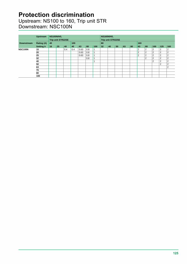
125
Protection discriminationUpstream: NS100 to 160, Trip unit STRDownstream: NSC100N
Upstream NS100N/H/L NS160N/H/L
Trip unit STR22SE Trip unit STR22SE
Downstream Rating (A) 40 100 80 160
Setting Ir 16 25 40 40 63 80 100 32 40 50 63 80 63 80 100 125 160NSC100N 15 0.4 0.4 0.63 0.8 1 2 2 2 2 2
20 0.63 0.8 1 2 2 2 2 225 0.63 0.8 1 2 2 2 2 232 0.8 1 2 2 2 240 1 2 2 250 2 263 27080100

126
Protection discriminationUpstream: NS250 to 630, Trip unit STRDownstream: NS400 to 630, NSC100N
Upstream NS250N/H/L NS400N/H/L NS630N/H/L
Trip unit STR22SE Trip unit STR23SE/53UE Trip unit STR23SE/53UE
Downstream Rating (A) 250 400 630
Setting Ir 100 125 160 200 250 160 200 250 320 400 250 320 400 500 630NS400N 160 8 8 8 8 8
200 8 8 8 8250 8 8 8320 8 8400 8
NS400H 160 8 8 8 8 8200 8 8 8 8250 8 8 8320 8 8400 8
NS400L 160 8 8 8 8 8200 8 8 8 8250 8 8 8320 8 8400 8
NS630N 250320400500630
NS630H 250320400500630
NS630L 250320400500630
NSC100N ≤ 25 T T T T T T T T T T T T T T T32 T T T T T T T T T T T T T T T40 T T T T T T T T T T T T T T T50 T T T T T T T T T T T T T T63 T T T T T T T T T T T T T70 T T T T T T T T T T T80 T T T T T T T T T T T100 T T T T T T T T T

127
Protection discriminationUpstream: C801 to C1251Downstream: DPN N, XC40, C60, NC100, NG125, NS100 to 250
Upstream C801N/H/C1001N/H/C1251N/H C801N/H C1001N/H/C1251N/H
Trip unit STR25DE Trip unit STR35SE/GE/ME/55UE Trip unit STR35SE/GE/ME/55UE
Downstream Rating (A) 800 1000 1250 800 1000 1250
Setting Ir 320 400 500 630 800 1000 1250 320 400 500 630 800 400 500 630 800 1000 1250DPN N, C60 T T T T T T T T T T T T T T T T T TNC100, NG125 T T T T T T T T T T T T T T T T T TNS100N 16 3.2 4 5 6.3 10 18 T T T T T T T T T T T TTrip unit TM-D 25 3.2 4 5 6.3 10 18 T T T T T T T T T T T T
32 3.2 4 5 6.3 10 18 T T T T T T T T T T T T40 3.2 4 5 6.3 10 18 T T T T T T T T T T T T50 3.2 4 5 6.3 10 18 T T T T T T T T T T T T63 3.2 4 5 6.3 10 18 T T T T T T T T T T T T80 3.2 4 5 6.3 10 18 T T T T T T T T T T T T100 3.2 4 5 6.3 10 18 T T T T T T T T T T T T
NS100H 16 3.2 4 5 6.3 10 18 30 50 50 50 50 50 T T T T T TTrip unit TM-D 25 3.2 4 5 6.3 10 18 30 50 50 50 50 50 T T T T T T
32 3.2 4 5 6.3 10 18 T 50 50 50 50 50 T T T T T T40 3.2 4 5 6.3 10 18 30 50 50 50 50 50 T T T T T T50 3.2 4 5 6.3 10 18 T 50 50 50 50 50 T T T T T T63 3.2 4 5 6.3 10 18 30 50 50 50 50 50 T T T T T T80 3.2 4 5 6.3 10 18 30 50 50 50 50 50 T T T T T T100 3.2 4 5 6.3 10 18 30 50 50 50 50 50 T T T T T T
NS100L 16 3.2 4 5 6.3 10 18 30 50 50 50 50 50 T T T T T TTrip unit TM-D 25 3.2 4 5 6.3 10 18 30 50 50 50 50 50 T T T T T T
32 3.2 4 5 6.3 10 18 T 50 50 50 50 50 T T T T T T40 3.2 4 5 6.3 10 18 30 50 50 50 50 50 T T T T T T50 3.2 4 5 6.3 10 18 T 50 50 50 50 50 T T T T T T63 3.2 4 5 6.3 10 18 30 50 50 50 50 50 T T T T T T80 3.2 4 5 6.3 10 18 30 50 50 50 50 50 T T T T T T100 3.2 4 5 6.3 10 18 30 50 50 50 50 50 T T T T T T
NS160N ≤≤≤≤≤ 63 3.2 4 5 6.3 10 18 30 T T T T T T T T T T TTrip unit TM-D 80 3.2 4 5 6.3 10 18 30 T T T T T T T T T T T
100 3.2 4 5 6.3 10 18 30 T T T T T T T T T T T125 3.2 4 5 6.3 10 18 30 T T T T T T T T T T T160 4 5 6.3 10 18 30 T T T T T T T T T T T
NS160H ≤≤≤≤≤ 63 3.2 4 5 6.3 10 18 30 45 45 45 45 45 T T T T T TTrip unit TM-D 80 3.2 4 5 6.3 10 18 30 45 45 45 45 45 T T T T T T
100 3.2 4 5 6.3 10 18 30 45 45 45 45 45 T T T T T T125 3.2 4 5 6.3 10 18 30 45 45 45 45 45 T T T T T T160 4 5 6.3 10 18 30 45 45 45 45 45 T T T T T T
NS160L ≤≤≤≤≤ 63 3.2 4 5 6.3 10 18 30 45 45 45 45 45 T T T T T TTrip unit TM-D 80 3.2 4 5 6.3 10 18 30 45 45 45 45 45 T T T T T T
100 3.2 4 5 6.3 10 18 30 45 45 45 45 45 T T T T T T125 3.2 4 5 6.3 10 18 30 45 45 45 45 45 T T T T T T160 4 5 6.3 10 18 30 45 45 45 45 45 T T T T T T
NS250N ≤≤≤≤≤ 100 3.2 4 5 6.3 8 15 24 T T T T T T T T T T TTrip unit TM-D 125 4 5 6.3 8 15 24 T T T T T T T T T T
160 5 6.3 8 15 24 T T T T T T T T T T200 6.3 8 15 24 T T T T T T T T250 8 15 24 T T T T T T
NS250H/L ≤≤≤≤≤ 100 3.2 4 5 6.3 8 15 24 40 40 40 40 40 T T T T T TTrip unit TM-D 125 4 5 6.3 8 15 24 40 40 40 40 T T T T T T
160 5 6.3 8 15 24 40 40 40 40 T T T T T T200 6.3 8 15 24 40 40 40 T T T T T250 8 15 24 40 40 T T T T
NS100N 40 3.2 4 5 6.3 10 18 T T T T T T T T T T T TTrip unit STR22SE 100 3.2 4 5 6.3 10 18 T T T T T T T T T T T TNS100H/L 40 3.2 4 5 6.3 10 18 30 50 50 50 50 50 T T T T T TTrip unit STR22SE 100 3.2 4 5 6.3 10 18 30 50 50 50 50 50 T T T T T TNS160N 40 3.2 4 5 6.3 10 18 30 T T T T T T T T T T TTrip unit STR22SE 100 3.2 4 5 6.3 10 18 30 T T T T T T T T T T T
160 3.2 4 5 6.3 10 18 30 T T T T T T T T T T TNS160H/L 40 3.2 4 5 6.3 10 18 30 45 45 45 45 45 T T T T T TTrip unit STR22SE 100 3.2 4 5 6.3 10 18 30 45 45 45 45 45 T T T T T T
160 3.2 4 5 6.3 10 18 30 45 45 45 45 45 T T T T T TNS250N ≤≤≤≤≤ 100 3.2 4 5 6.3 8 15 24 T T T T T T T T T T TTrip unit STR22SE 160 3.2 4 5 6.3 8 15 24 T T T T T T T T T T T
250 5 6.3 8 15 24 T T T T T T T TNS250H/L ≤≤≤≤≤ 100 3.2 4 5 6.3 8 15 24 40 40 40 40 40 T T T T T TTrip unit STR22SE 160 3.2 4 5 6.3 8 15 24 40 40 40 40 40 T T T T T T
250 5 6.3 8 15 24 40 40 40 T T T T T

128
Protection discriminationUpstream: C801 to C1251, CMDownstream: DPN N, XC40, C60, NC100, NG125, NS100 to 250
(1) With trip unit STCM2-STCM3.
Upstream C801N/H C1001N/H/C1251N/H C801L C1001L CM
Trip unit STR45AE Trip unit STR45AE Trip unit Trip unit N/H (1)
STR35SE/GE/ME/55UE STR35SE/GE/ME/55UE
Downstream Rating (A) 800 1000 1250 800 1000 all
Setting Ir 320 400 500 630 800 400 500 630 800 1000 1250 320 400 500 630 800 400 500 630 800 1000DPN N, XC40, C60 T T T T T T T T T T T T T T T T T T T T T TNC100, NG125 T T T T T T T T T T T T T T T T T T T T T TNS100N 16 T T T T T T T T T T T 6.4 6.4 6.4 6.4 6.4 8 8 8 8 8 TTrip unit TM-D 25 T T T T T T T T T T T 6.4 6.4 6.4 6.4 6.4 8 8 8 8 8 T
32 T T T T T T T T T T T 6.4 6.4 6.4 6.4 6.4 8 8 8 8 8 T40 T T T T T T T T T T T 6.4 6.4 6.4 6.4 6.4 8 8 8 8 8 T50 T T T T T T T T T T T 6.4 6.4 6.4 6.4 6.4 8 8 8 8 8 T63 T T T T T T T T T T T 6.4 6.4 6.4 6.4 6.4 8 8 8 8 8 T80 T T T T T T T T T T T 6.4 6.4 6.4 6.4 6.4 8 8 8 8 8 T100 T T T T T T T T T T T 6.4 6.4 6.4 6.4 6.4 8 8 8 8 8 T
NS100H 16 T T T T T T T T T T T 6.4 6.4 6.4 6.4 6.4 8 8 8 8 8 TTrip unit TM-D 25 T T T T T T T T T T T 6.4 6.4 6.4 6.4 6.4 8 8 8 8 8 T
32 T T T T T T T T T T T 6.4 6.4 6.4 6.4 6.4 8 8 8 8 8 T40 T T T T T T T T T T T 6.4 6.4 6.4 6.4 6.4 8 8 8 8 8 T50 T T T T T T T T T T T 6.4 6.4 6.4 6.4 6.4 8 8 8 8 8 T63 T T T T T T T T T T T 6.4 6.4 6.4 6.4 6.4 8 8 8 8 8 T80 T T T T T T T T T T T 6.4 6.4 6.4 6.4 6.4 8 8 8 8 8 T100 T T T T T T T T T T T 6.4 6.4 6.4 6.4 6.4 8 8 8 8 8 T
NS100L 16 T T T T T T T T T T T 6.4 6.4 6.4 6.4 6.4 8 8 8 8 8 TTrip unit TM-D 25 T T T T T T T T T T T 6.4 6.4 6.4 6.4 6.4 8 8 8 8 8 T
32 T T T T T T T T T T T 6.4 6.4 6.4 6.4 6.4 8 8 8 8 8 T40 T T T T T T T T T T T 6.4 6.4 6.4 6.4 6.4 8 8 8 8 8 T50 T T T T T T T T T T T 6.4 6.4 6.4 6.4 6.4 8 8 8 8 8 T63 T T T T T T T T T T T 6.4 6.4 6.4 6.4 6.4 8 8 8 8 8 T80 T T T T T T T T T T T 6.4 6.4 6.4 6.4 6.4 8 8 8 8 8 T100 T T T T T T T T T T T 6.4 6.4 6.4 6.4 6.4 8 8 8 8 8 T
NS160/N ≤ ≤ ≤ ≤ ≤ 63 T T T T T T T T T T T 6.4 6.4 6.4 6.4 6.4 8 8 8 8 8 TTrip unit TM-D 80 T T T T T T T T T T T 6.4 6.4 6.4 6.4 6.4 8 8 8 8 8 T
100 T T T T T T T T T T T 6.4 6.4 6.4 6.4 6.4 8 8 8 8 8 T125 T T T T T T T T T T 6.4 6.4 6.4 6.4 8 8 8 8 8 T160 T T T T T T T T T 6.4 6.4 6.4 8 8 8 8 8 T
NS160H ≤≤≤≤≤ 63 T T T T T T T T T T T 6.4 6.4 6.4 6.4 6.4 8 8 8 8 8 TTrip unit TM-D 80 T T T T T T T T T T T 6.4 6.4 6.4 6.4 6.4 8 8 8 8 8 T
100 T T T T T T T T T T T 6.4 6.4 6.4 6.4 6.4 8 8 8 8 8 T125 T T T T T T T T T T 6.4 6.4 6.4 6.4 8 8 8 8 8 T160 T T T T T T T T T 6.4 6.4 6.4 8 8 8 8 8 T
NS160L ≤≤≤≤≤ 63 T T T T T T T T T T T 6.4 6.4 6.4 6.4 6.4 8 8 8 8 8 TTrip unit TM-D 80 T T T T T T T T T T T 6.4 6.4 6.4 6.4 6.4 8 8 8 8 8 T
100 T T T T T T T T T T T 6.4 6.4 6.4 6.4 6.4 8 8 8 8 8 T125 T T T T T T T T T T 6.4 6.4 6.4 6.4 8 8 8 8 8 T160 T T T T T T T T T 6.4 6.4 6.4 8 8 8 8 8 T
NS250N ≤≤≤≤≤ 100 T T T T T T T T T T T 6.4 6.4 6.4 6.4 6.4 8 8 8 8 8 TTrip unit TM-D 125 T T T T T T T T T T 6.4 6.4 6.4 6.4 8 8 8 8 8 T
160 T T T T T T T T T 6.4 6.4 6.4 8 8 8 8 8 T200 T T T T T T T T T 6.4 6.4 6.4 8 8 8 8 8 T250 T T T T T T T 6.4 8 8 8 8 8 T
NS250H/L ≤≤≤≤≤ 100 T T T T T T T T T T T 6.4 6.4 6.4 6.4 6.4 8 8 8 8 8 TTrip unit TM-D 125 T T T T T T T T T T 6.4 6.4 6.4 6.4 8 8 8 8 8 T
160 T T T T T T T T T 6.4 6.4 6.4 8 8 8 8 8 T200 T T T T T T T T T 6.4 6.4 6.4 8 8 8 8 8 T250 T T T T T T T 6.4 8 8 8 8 8 T
NS100N 40 T T T T T T T T T T T 6.4 6.4 6.4 6.4 6.4 8 8 8 8 8 TTrip unit STR22SE 100 T T T T T T T T T T T 6.4 6.4 6.4 6.4 6.4 8 8 8 8 8 TNS100H/L 40 T T T T T T T T T T T 6.4 6.4 6.4 6.4 6.4 8 8 8 8 8 TTrip unit STR22SE 100 T T T T T T T T T T T 6.4 6.4 6.4 6.4 6.4 8 8 8 8 8 TNS160N 40 T T T T T T T T T T T 6.4 6.4 6.4 6.4 6.4 8 8 8 8 8 TTrip unit STR22SE 100 T T T T T T T T T T T 6.4 6.4 6.4 6.4 6.4 8 8 8 8 8 T
160 T T T T T T T T T T T 6.4 6.4 6.4 6.4 6.4 8 8 8 8 8 TNS160H/L 40 T T T T T T T T T T T 6.4 6.4 6.4 6.4 6.4 8 8 8 8 8 TTrip unit STR22SE 100 T T T T T T T T T T T 6.4 6.4 6.4 6.4 6.4 8 8 8 8 8 T
160 T T T T T T T T T T T 6.4 6.4 6.4 6.4 8 8 8 8 8 TNS250N ≤≤≤≤≤ 100 T T T T T T T T T T T 6.4 6.4 6.4 6.4 6.4 3.2 4 5 6.3 8 TTrip unit STR22SE 160 T T T T T T T T T T T 6.4 6.4 6.4 6.4 6.4 3.2 4 5 6.3 8 T
250 T T T T T T T T T T 6.4 6.4 6.4 6.4 3.2 4 5 6.3 8 TNS250H/L ≤≤≤≤≤ 100 T T T T T T T T T T T 6.4 6.4 6.4 6.4 6.4 3.2 4 5 6.3 8 TTrip unit STR22SE 160 T T T T T T T T T T T 6.4 6.4 6.4 6.4 6.4 3.2 4 5 6.3 8 T
250 T T T T T T T T T T 6.4 6.4 6.4 6.4 3.2 4 5 6.3 8 T

129
Protection discriminationUpstream: C801 to C1251Downstream: DPN N, XC40, C60, NC100, NG125, NS400 to 630
Upstream C801N/H/C1001N/H/C1251N/H C801N/H C1001N/H/C1251N/H
Trip unit STR25DE Trip unit STR35SE/GE/ME/55UE Trip unit STR35SE/GE/ME/55UE
Downstream Rating (A) 800 1000 1250 800 1000 1250
Setting Ir 320 400 500 630 800 1000 1250 320 400 500 630 800 400 500 630 800 1000 1250NS400N 160 3.2 4 5 6.3 8 10 12 12 12 12 12 12 T T T T T T
200 3.2 4 5 6.3 8 10 12 12 12 12 12 12 T T T T T T250 4 5 6.3 8 10 12 12 12 12 12 T T T T T320 5 6.3 8 10 12 12 12 12 T T T T400 6.3 8 10 12 12 12 T T T
NS400H 160 3.2 4 5 6.3 8 10 12 12 12 12 12 12 45 45 45 45 45 45200 3.2 4 5 6.3 8 10 12 12 12 12 12 12 45 45 45 45 45 45250 4 5 6.3 8 10 12 12 12 12 12 45 45 45 45 45320 5 6.3 8 10 12 12 12 12 45 45 45 45400 6.3 8 10 12 12 12 45 45 45
NS400L 160 3.2 4 5 6.3 8 10 12 12 12 12 12 12 45 45 45 45 45 45200 3.2 4 5 6.3 8 10 12 12 12 12 12 12 45 45 45 45 45 45250 4 5 6.3 8 10 12 12 12 12 12 45 45 45 45 45320 5 6.3 8 10 12 12 12 12 45 45 45 45400 6.3 8 10 12 12 12 45 45 45
NS630N 250 4 5 6.3 8 10 12 12 12 12 12 40 40 40 40 40 40320 5 6.3 8 10 12 12 12 12 40 40 40 40 40400 6.3 8 10 12 12 12 40 40 40 40500 8 10 12 12 40 40 40630 10 12 40 40
NS630H 250 4 5 6.3 8 10 12 12 12 12 12 40 40 40 40 40 40320 5 6.3 8 10 12 12 12 12 40 40 40 40 40400 6.3 8 10 12 12 12 40 40 40 40500 8 10 12 12 40 40 40630 10 12 40 40
NS630L 250 4 5 6.3 8 10 12 12 12 12 12 40 40 40 40 40 40320 5 6.3 8 10 12 12 12 12 40 40 40 40 40400 6.3 8 10 12 12 12 40 40 40 40500 8 10 12 12 40 40 40630 10 12 40 40
NSC100N ≤≤≤≤≤ 25 3.2 4 10 15 T T T T T T T T T T T T T T32 3.2 4 10 15 T T T T T T T T T T T T T T40 3.2 4 10 15 T T T T T T T T T T T T T T50 3.2 4 10 15 T T T T T T T T T T T T T T63 3.2 4 10 15 T T T T T T T T T T T T T T70 3.2 4 10 15 T T T T T T T T T T T T T T80 3.2 4 10 15 T T T T T T T T T T T T T T100 3.2 4 10 15 T T T T T T T T T T T T T T
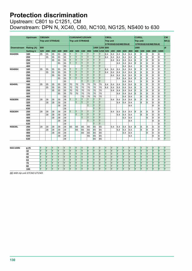
130
Protection discriminationUpstream: C801 to C1251, CMDownstream: DPN N, XC40, C60, NC100, NG125, NS400 to 630
(1) With trip unit STCM2-STCM3.
Upstream C801N/H C1001N/H/C1251N/H C801L C1001L CM
Trip unit STR45AE Trip unit STR45AE Trip unit Trip unit N/H (1)
STR35SE/GE/ME/55UE STR35SE/GE/ME/55UE
Downstream Rating (A) 800 1000 1250 800 1000 all
Setting Ir 320 400 500 630 800 400 500 630 800 1000 1250 320 400 500 630 800 400 500 630 800 1000NS400N 160 35 35 35 35 35 T T T T T T 6.4 6.4 6.4 6.4 6.4 8 8 8 8 8 T
200 35 35 35 35 T T T T T T 6.4 6.4 6.4 6.4 6.4 8 8 8 8 8 T250 35 35 35 T T T T T T 6.4 6.4 6.4 6.4 8 8 8 8 8 T320 35 35 T T T T T T 6.4 6.4 6.4 8 8 8 8 8 T400 35 T T T T 6.4 6.4 8 8 8 8 T
NS400H 160 35 35 35 35 35 T T T T T T 6.4 6.4 6.4 6.4 6.4 8 8 8 8 8 T200 35 35 35 35 T T T T T T 6.4 6.4 6.4 6.4 6.4 8 8 8 8 8 T250 35 35 35 T T T T T T 6.4 6.4 6.4 6.4 8 8 8 8 8 T320 35 35 T T T T T T 6.4 6.4 6.4 8 8 8 8 8 T400 35 T T T T 6.4 6.4 8 8 8 8 T
NS400L 160 35 35 35 35 35 70 70 70 70 70 70 6.4 6.4 6.4 6.4 6.4 8 8 8 8 8 T200 35 35 35 35 70 70 70 70 70 70 6.4 6.4 6.4 6.4 6.4 8 8 8 8 8 T250 35 35 35 70 70 70 70 70 70 6.4 6.4 6.4 6.4 8 8 8 8 8 T320 35 35 70 70 70 70 70 70 6.4 6.4 6.4 8 8 8 8 8 T400 35 70 70 70 70 6.4 6.4 8 8 8 8 T
NS630N 250 28 28 28 28 28 T T T T T T 6.4 6.4 6.4 6.4 8 8 8 8 8 T320 28 28 28 28 T T T T T 6.4 6.4 6.4 8 8 8 8 T400 28 28 T T T 6.4 8 8 T630 28 T T 8 T
NS630H 250 28 28 28 28 28 T T T T T T 6.4 6.4 6.4 6.4 8 8 8 8 8 T320 28 28 28 28 T T T T T 6.4 6.4 6.4 8 8 8 8 T400 28 28 28 T T T T 6.4 6.4 8 8 8 T500 28 28 T T T 6.4 8 8 T630 28 T T 8 T
NS630L 250 28 28 28 28 28 65 65 65 65 65 65 6.4 6.4 6.4 6.4 8 8 8 8 8 T320 28 28 28 28 65 65 65 65 65 6.4 6.4 6.4 8 8 8 8 T400 28 28 28 65 65 65 65 6.4 6.4 8 8 8 T500 28 28 65 65 65 6.4 8 8 T630 28 65 65 8 T
NSC100N ≤≤≤≤≤ 25 T T T T T T T T T T T T T T T T T T T T T T32 T T T T T T T T T T T T T T T T T T T T T T40 T T T T T T T T T T T T T T T T T T T T T T50 T T T T T T T T T T T T T T T T T T T T T T63 T T T T T T T T T T T T T T T T T T T T T T70 T T T T T T T T T T T T T T T T T T T T T T80 T T T T T T T T T T T T T T T T T T T T T T100 T T T T T T T T T T T T T T T T T T T T T T

131
Protection discriminationUpstream: C801 to C1251Downstream: C801 to C1251, CM, Masterpact
Upstream C801N/H/C1001N/H/C1251N/H C801N/H C1001N/H/C1251N/H
Trip unit STR25DE Trip unit STR35SE/GE/ME/55UE Trip unit STR35SE/GE/ME/55UE
Downstream Rating (A) 800 1000 1250 800 1000 1250
Setting Ir 320 400 500 630 800 1000 1250 320 400 500 630 800 400 500 630 800 1000 1250C801N 320 6.3 8 10 12.5 12 12 15 15 15 15Trip unit STR25DE 400 8 10 12.5 12 15 15 15
500 8 10 12.5 12 15 15 15630 10 12.5 15 15800
C801H 320 6.3 8 10 12.5 12 12 15 15 15 15Trip unit STR25DE 400 8 10 12.5 12 15 15 15
500 8 10 12.5 12 15 15 15630 10 12.5 15 15800
C801L 320400500630800
C1001N 400 8 10 12.5 12 15 15 15Trip unit STR25DE 500 8 10 12.5 12 15 15 15
630 10 12.5 15 158001000
C1001H 400 8 10 12.5 12 15 15 15Trip unit STR25DE 500 8 10 12.5 12 15 15
630 10 12.5 15 158001000
C1001L 4005006308001000
C1251N 500 8 10 12.5 12 15 15 15Trip unit STR25DE 630 10 12.5 15 15
80010001250
C1251H 500 8 10 12.5 12 15 15 15Trip unit STR25DE 630 10 12.5 15 15
80010001250
CM 12501600200025003200
Masterpact M08H1/H2 M10STR28D M12
M16M20M25M32M40M50M63
Masterpact L M08STR28D M10
M12M16M20M25
Nota :c C801N/H with trip unit STR45AE : no distrimination with the dowstream devices give, in this tablec upstream values CM N/H are to be read with distrimination:v CM (trip unit STCM1)v Masterpact L (trip unit STR38S - 68U).

132
Protection discriminationUpstream: C801 to C1251, CMDownstream: C801 to C1251, CM, Masterpact
Upstream C1001N/H/C1251N/H C801L C1001L CM N/H
Trip unit STR45AE Trip unit Trip unit Trip unit STCM2-STCM3
STR35SE/GE/ME/55UE STR35SE/GE/ME/55UE
Downstream Rating (A) 800 1000 1250 800 1000 1250 1600 2000 2500 3200
Setting Ir 400 500 630 800 1000 1250 320 400 500 630 800 400 500 630 800 1000 1250 1600 2000 2500 3200C801N 320 15 15 15 15 15 45 45 45 45 45Trip unit STR25DE 400 15 15 15 15 45 45 45 45 45
500 15 15 15 45 45 45 45 45630 15 15 45 45 45 45 45800 15 45 45 45 45
C801H 320 15 15 15 15 15 45 45 45 45 45Trip unit STR25DE 400 15 15 15 15 45 45 45 45 45
500 15 15 15 45 45 45 45 45630 15 15 45 45 45 45 45800 15 45 45 45 45
C801L 320 15 15 15 15 15 80 80 80 80 80400 15 15 15 15 80 80 80 80 80500 15 15 15 80 80 80 80 80630 15 15 80 80 80 80 80800 15 80 80 80 80
C1001N 400 15 15 15 15 45 45 45 45 45Trip unit STR25DE 500 15 15 15 45 45 45 45 45
630 15 15 45 45 45 45 45800 15 45 45 45 451000 45 45 45
C1001H 400 15 15 15 15 45 45 45 45 45Trip unit STR25DE 500 15 15 15 45 45 45 45 45
630 15 15 45 45 45 45 45800 15 45 45 45 451000 45 45 45
C1001L 400 15 15 15 15 80 80 80 80 80500 15 15 15 80 80 80 80 80630 15 15 80 80 80 80 80800 15 80 80 80 801000 80 80 80
C1251N 500 15 15 15 45 45 45 45 45Trip unit STR25DE 630 15 15 45 45 45 45 45
800 15 45 45 45 451000 45 45 451250 45 45
C1251H 500 15 15 15 45 45 45 45 45Trip unit STR25DE 630 15 15 45 45 45 45 45
800 15 45 45 45 451000 45 45 451250 45 45
CM 1250 35 35 351600 35 352000 3525003200
Masterpact M08 35 35 35H1/H2 M10 35 35STR28D M12 35
M16M20M25M32M40M50M63
Masterpact L M08 40 40 40 35 35STR28D M10 40 40 35 35
M12 40 35 35M16 35 35M20 35M25

133
Protection discriminationUpstream: Masterpact NWDownstream: Multi 9, NS100 to 630, NSC100N
Upstream Masterpact NW - H1 - H2
Trip unit Micrologic 5.0 - 6.0 - 7.0 - Inst: 15 In
NW08 NW10 NW12 NW16 NW20 NW25 NW32 NW40 NW50 NW63
Downstream Rating (A) 800 1000 1250 1600 2000 2500 3200 4000 5000 6300
Setting Ir 800 1000 1250 1600 2000 2500 3200 4000 5000 6300DPN N T T T T T T T T T TC60 T T T T T T T T T TXC40 T T T T T T T T T TNC100H T T T T T T T T T TNS100N T T T T T T T T T TNS100H T T T T T T T T T TNS100L T T T T T T T T T TNS160N T T T T T T T T T TNS160H T T T T T T T T T TNS160L T T T T T T T T T TNS250N T T T T T T T T T TNS250H/L T T T T T T T T T TNS400N 160 T T T T T T T T T TSTR23SE 200 T T T T T T T T T TSTR53UE 250 T T T T T T T T T T
320 T T T T T T T T T T400 T T T T T T T T T T
NS400H 160 T T T T T T T T T TSTR23SE 200 T T T T T T T T T TSTR53UE 250 T T T T T T T T T T
320 T T T T T T T T T T400 T T T T T T T T T T
NS400L 160 T T T T T T T T T TSTR23SE 200 T T T T T T T T T TSTR53UE 250 T T T T T T T T T T
320 T T T T T T T T T T400 T T T T T T T T T T
NS630N 250 T T T T T T T T T TSTR23SE 320 T T T T T T T T T TSTR53UE 400 T T T T T T T T T T
500 T T T T T T T T T T630 T T T T T T T T T
NS630H 250 T T T T T T T T T TSTR23SE 320 T T T T T T T T T TSTR53UE 400 T T T T T T T T T T
500 T T T T T T T T T T630 T T T T T T T T T
NS630L 250 T T T T T T T T T TSTR23SE 320 T T T T T T T T T TSTR53UE 400 T T T T T T T T T T
500 T T T T T T T T T T630 T T T T T T T T T
NSC100N T T T T T T T T T T

134
Protection discriminationUpstream: Masterpact NWDownstream: Multi 9, NS100 to 630, NSC100N
Upstream Masterpact NW - H1 - H2
Trip unit Micrologic 5.0 - 6.0 - 7.0 - Inst: OFF
NW08 NW10 NW12 NW16 NW20 NW25 NW32 NW40 NW50 NW63
Downstream Rating (A) 800 1000 1250 1600 2000 2500 3200 4000 5000 6300
Setting Ir 800 1000 1250 1600 2000 2500 3200 4000 5000 6300DPN N T T T T T T T T T TC60 T T T T T T T T T TXC40 T T T T T T T T T TNC100H T T T T T T T T T TNC125H T T T T T T T T T TNS100N T T T T T T T T T TNS100H T T T T T T T T T TNS100L T T T T T T T T T TNS160N T T T T T T T T T TNS160H T T T T T T T T T TNS160L T T T T T T T T T TNS250N T T T T T T T T T TNS250H/L T T T T T T T T T TNS400N 160 T T T T T T T T T TSTR23SE 200 T T T T T T T T T TSTR53UE 250 T T T T T T T T T T
320 T T T T T T T T T T400 T T T T T T T T T T
NS400H 160 T T T T T T T T T TSTR23SE 200 T T T T T T T T T TSTR53UE 250 T T T T T T T T T T
320 T T T T T T T T T T400 T T T T T T T T T T
NS400L 160 T T T T T T T T T TSTR23SE 200 T T T T T T T T T TSTR53UE 250 T T T T T T T T T T
320 T T T T T T T T T T400 T T T T T T T T T T
NS630N 250 T T T T T T T T T TSTR23SE 320 T T T T T T T T T TSTR53UE 400 T T T T T T T T T T
500 T T T T T T T T T T630 T T T T T T T T T T
NS630H 250 T T T T T T T T T TSTR23SE 320 T T T T T T T T T TSTR53UE 400 T T T T T T T T T T
500 T T T T T T T T T T630 T T T T T T T T T T
NS630L 250 T T T T T T T T T TSTR23SE 320 T T T T T T T T T TSTR53UE 400 T T T T T T T T T T
500 T T T T T T T T T T630 T T T T T T T T T T
NSC100N T T T T T T T T T T

135
Protection discriminationUpstream: Masterpact NWDownstream: Multi 9, NS100 to 630, NSC100
Upstream Masterpact NW H3 Masterpact NW H3
Trip unit Micrologic 5.0 - 6.0 - 7.0 Micrologic 5.0 - 6.0 - 7.0
Inst: 15 In Inst: OFF
NW20 NW25 NW32 NW40 NW20 NW25 NW32 NW40
Downstream Rating (A) 2000 2500 3200 4000 2000 2500 3200 4000
Setting Ir 2000 2500 3200 4000 2000 2500 3200 4000DPN N T T T T T T T TC60 T T T T T T T TXC40 T T T T T T T TNC100H T T T T T T T TNS100N T T T T T T T TNS100H T T T T T T T TNS100L T T T T T T T TNS160N T T T T T T T TNS160H T T T T T T T TNS160L T T T T T T T TNS250N T T T T T T T TNS250H/L T T T T T T T TNS400N 160 T T T T T T T TSTR23SE 200 T T T T T T T TSTR53UE 250 T T T T T T T T
320 T T T T T T T T400 T T T T T T T T
NS400H 160 T T T T T T T TSTR23SE 200 T T T T T T T TSTR53UE 250 T T T T T T T T
320 T T T T T T T T400 T T T T T T T T
NS400L 160 T T T T T T T TSTR23SE 200 T T T T T T T TSTR53UE 250 T T T T T T T T
320 T T T T T T T T400 T T T T T T T T
NS630N 250 T T T T T T T TSTR23SE 320 T T T T T T T TSTR53UE 400 T T T T T T T T
500 T T T T T T T T630 T T T T T T T T
NS630H 250 T T T T T T T TSTR23SE 320 T T T T T T T TSTR53UE 400 T T T T T T T T
500 T T T T T T T T630 T T T T T T T T
NS630L 250 T T T T T T T TSTR23SE 320 T T T T T T T TSTR53UE 400 T T T T T T T T
500 T T T T T T T T630 T T T T T T T T
NSC100N T T T T T T T T

136
Protection discriminationUpstream: Masterpact NWDownstream: Multi 9, NS100 to 630, NSC100
Upstream Masterpact NW L1 Masterpact NW L1
Trip unit Micrologic 5.0 - 6.0 - 7.0 Micrologic 5.0 - 6.0 - 7.0
Inst: 15 In Inst: OFF
NW08 NW10 NW12 NW16 NW20 NW08 NW10 NW12 NW16 NW20
Downstream Rating (A) 800 1000 1250 1600 2000 800 1000 1250 1600 2000
Setting Ir 800 1000 1250 1600 2000 800 1000 1250 1600 2000DPN N T T T T T T T T T TC60 T T T T T T T T T TXC40 T T T T T T T T T TNC100H T T T T T T T T T TNS100N T T T T T T T T T TNS100H T T T T T T T T T TNS100L T T T T T T T T T TNS160N T T T T T T T T T TNS160H T T T T T T T T T TNS160L T T T T T T T T T TNS250N T T T T T T T T T TNS250H/L T T T T T T T T T TNS400N 160 T T T T T T T T T TSTR23SE 200 T T T T T T T T T TSTR53UE 250 T T T T T T T T T T
320 T T T T T T T T T T400 T T T T T T T T T T
NS400H 160 T T T T T T T T T TSTR23SE 200 T T T T T T T T T TSTR53UE 250 T T T T T T T T T T
320 T T T T T T T T T T400 T T T T T T T T T T
NS400L 160 T T T T T T T T T TSTR23SE 200 T T T T T T T T T TSTR53UE 250 T T T T T T T T T T
320 T T T T T T T T T T400 T T T T T T T T T T
NS630N 250 T T T T T T T T T TSTR23SE 320 T T T T T T T T T TSTR53UE 400 T T T T T T T T T T
500 T T T T T T T T T T630 T T T T T T T T T
NS630H 250 T T T T T T T T T TSTR23SE 320 T T T T T T T T T TSTR53UE 400 T T T T T T T T T T
500 T T T T T T T T T T630 T T T T T T T T T
NS630L 250 T T T T T T T T T TSTR23SE 320 T T T T T T T T T TSTR53UE 400 T T T T T T T T T T
500 T T T T T T T T T T630 T T T T T T T T T
NSC100N T T T T T T T T T T

137
Protection discriminationUpstream: Masterpact NWDownstream: C801 to C1251, CM
Upstream Masterpact NW - H1 - H2Trip unit Micrologic 5.0 - 6.0 - 7.0 - Inst: 15 In
NW08 NW10 NW12 NW16 NW20 NW25 NW32 NW40 NW50 NW63Downstream Rating (A) 800 1000 1250 1600 2000 2500 3200 4000 5000 6300
Setting Ir 800 1000 1250 1600 2000 2500 3200 4000 5000 6300
C801N 320 12.5 15 18.7 24 30 37.5 48 T T T
400 12.5 15 18.7 24 30 37.5 48 T T T
500 12.5 15 18.7 24 30 37.5 48 T T T
630 15 18.7 24 30 37.5 48 T T T
800 18.7 24 30 37.5 48 T T T
C801H 320 12.5 15 18.7 24 30 37.5 48 60 T T
400 12.5 15 18.7 24 30 37.5 48 60 T T
500 12.5 15 18.7 24 30 37.5 48 60 T T
630 15 18.7 24 30 37.5 48 60 T T
800 18.7 24 30 37.5 48 60 T T
C801L 320 12.5 15 18.7 24 30 37.5 60 T T T
400 12.5 15 18.7 24 30 37.5 60 T T T
500 12.5 15 18.7 24 30 37.5 60 T T T
630 15 18.7 24 30 37.5 60 T T T
800 18.7 24 30 37.5 60 T T T
C1001N 400 15 18.7 24 30 37.5 48 T T T
500 15 18.7 24 30 37.5 48 T T T
630 15 18.7 24 30 37.5 48 T T T
800 18.7 24 30 37.5 48 T T T
1000 24 30 37.5 48 T T T
C1001H 400 15 18.7 24 30 37.5 48 60 T T
500 15 18.7 24 30 37.5 48 60 T T
630 15 18.7 24 30 37.5 48 60 T T
800 18.7 24 30 37.5 48 60 T T
1000 24 30 37.5 48 60 T T
C1001L 400 15 18.7 24 30 37.5 48 T T T
500 15 18.7 24 30 37.5 48 T T T
630 15 18.7 24 30 37.5 48 T T T
800 18.7 24 30 37.5 48 T T T
1000 24 30 37.5 48 T T T
C1251N 500 18.7 24 30 37.5 48 T T T
630 18.7 24 30 37.5 48 T T T
800 18.7 24 30 37.5 48 T T T
1000 24 30 37.5 48 T T T
1250 30 37.5 48 T T T
C1251H 500 18.7 24 30 37.5 48 60 T T
630 18.7 24 30 37.5 48 60 T T
800 18.7 24 30 37.5 48 60 T T
1000 24 30 37.5 48 60 T T
1250 30 37.5 48 60 T T
CM 1250
N/H 1600
2000
2500
3200

138
Protection discriminationUpstream: Masterpact NWDownstream: C801 to C1251, CM
Upstream Masterpact NW - H1 - H2Trip unit Micrologic 5.0 - 6.0 - 7.0 - Inst: OFF
NW08 NW10 NW12 NW16 NW20 NW25 NW32 NW40 NW50 NW63Downstream Rating (A) 800 1000 1250 1600 2000 2500 3200 4000 5000 6300
Setting Ir 800 1000 1250 1600 2000 2500 3200 4000 5000 6300
C801N 320 T T T T T T T T T T
400 T T T T T T T T T T
500 T T T T T T T T T T
630 T T T T T T T T T
800 T T T T T T T T
C801H 320 T T T T T T T T T T
400 T T T T T T T T T T
500 T T T T T T T T T T
630 T T T T T T T T T
800 T T T T T T T T
C801L 320 T T T T T T T T T T
400 T T T T T T T T T T
500 T T T T T T T T T T
630 T T T T T T T T T
800 T T T T T T T T
C1001N 400 T T T T T T T T T
500 T T T T T T T T T
630 T T T T T T T T T
800 T T T T T T T T
1000 T T T T T T T
C1001H 400 T T T T T T T T T
500 T T T T T T T T T
630 T T T T T T T T T
800 T T T T T T T T
1000 T T T T T T T
C1001L 400 T T T T T T T T T
500 T T T T T T T T T
630 T T T T T T T T T
800 T T T T T T T T
1000 T T T T T T T
C1251N 500 T T T T T T T T
630 T T T T T T T T
800 T T T T T T T T
1000 T T T T T T T
1250 T T T T T T
C1251H 500 T T T T T T T T
630 T T T T T T T T
800 T T T T T T T T
1000 T T T T T T T
1250 T T T T T T
CM 1250
N/H 1600
2000
2500
3200

139
Protection discriminationUpstream: Masterpact NWDownstream: C801 to C1251, CM
Upstream Masterpact NW - H3 Masterpact NW H3Trip unit Micrologic 5.0-6.0-7.0 Micrologic 5.0-6.0-7.0
nst: 15In Inst: OFFNW20 NW25 NW32 NW40 NW20 NW25 NW32 NW40
Downstream Rating (A) 2000 2500 3200 4000 2000 2500 3200 4000Setting Ir 2000 2500 3200 4000 2000 2500 3200 4000
C801N 320 30 37.5 48 T T T T T
400 30 37.5 48 T T T T T
500 30 37.5 48 T T T T T
630 230 37.5 48 T T T T T
800 30 37.5 48 T T T T T
C801H 320 30 37.5 48 60 T T T T
400 30 37.5 48 60 T T T T
500 30 37.5 48 60 T T T T
630 30 37.5 48 60 T T T T
800 30 37.5 48 60 T T T T
C801L 320 30 37.5 60 T T T T T
400 30 37.5 60 T T T T T
500 30 37.5 60 T T T T T
630 30 37.5 60 T T T T T
800 30 37.5 60 T T T T T
C1001N 400 30 37.5 48 T T T T T
500 30 37.5 48 T T T T T
630 30 37.5 48 T T T T T
800 30 37.5 48 T T T T T
1000 30 37.5 48 T T T T T
C1001H 400 30 37.5 48 60 T T T T
500 30 37.5 48 60 T T T T
630 30 37.5 48 60 T T T T
800 30 37.5 48 60 T T T T
1000 30 37.5 48 60 T T T T
C1001L 400 30 37.5 60 T T T T T
500 30 37.5 60 T T T T T
630 30 37.5 60 T T T T T
800 30 37.5 60 T T T T T
1000 30 37.5 60 T T T T T
C1251N 500 30 37.5 48 T T T T T
630 30 37.5 48 T T T T T
800 30 37.5 48 T T T T T
1000 30 37.5 48 T T T T T
1250 30 37.5 48 T T T T T
C1251H 500
630
800
1000
1250
CM 1250
N/H 1600
2000
2500
3200

140
Protection discriminationUpstream: Masterpact NWDownstream: C801 to C1251, CM
Upstream Masterpact NW L1 Masterpact NW L1Trip unit Micrologic 5.0-6.0-7.0 Micrologic 5.0-6.0-7.0
IInst: 15In Inst: OFFNW08 NW10 NW12 NW16 NW20 NW08 NW10 NW12 NW16 NW20
Downstream Rating (A) 800 1000 1250 1600 2000 800 1000 1250 1600 2000Setting Ir 800 1000 1250 1600 2000 800 1000 1250 1600 2000
C801N 320 12 15 18.7 24 30 T T T T T
400 12 15 18.7 24 30 T T T T T
500 12 15 18.7 24 30 T T T T T
630 15 18.7 24 30 T T T T
800 18.7 24 30 T T T
C801H 320 12 15 18.7 24 30 50 50 50 50 50
400 12 15 18.7 24 30 50 50 50 50 50
500 12 15 18.7 24 30 50 50 50 50 50
630 15 18.7 24 30 50 50 50 50
800 18.7 24 30 50 50 50
C801L 320 12 15 18.7 24 30 90 90 90 90 90
400 12 15 18.7 24 30 90 90 90 90 90
500 12 15 18.7 24 30 90 90 90 90 90
630 15 18.7 24 30 90 90 90 90
800 18.7 24 30 90 90 90
C1001N 400 15 18.7 24 30 T T T T
500 15 18.7 24 30 T T T T
630 15 18.7 24 30 T T T T
800 18.7 24 30 T T T
1000 24 30 T T
C1001H 400 15 18.7 24 30 50 50 50 50
500 15 18.7 24 30 50 50 50 50
630 15 18.7 24 30 50 50 50 50
800 18.7 24 30 50 50 50
1000 24 30 50 50
C1001L 400 15 18.7 24 30 90 90 90 90
500 15 18.7 24 30 90 90 90 90
630 15 18.7 24 30 90 90 90 90
800 18.7 24 30 90 90 90
1000 24 30 90 90
C1251N 500 18.7 24 30 50 50 50
630 18.7 24 30 50 50 50
800 18.7 24 30 50 50 50
1000 24 30 50 50
1250 30 50
C1251H 500
630
800
1000
1250
CM 1250
N/H 1600
2000
2500
3200

141
Protection discriminationUpstream: Masterpact NWDownstream: Masterpact NW, Masterpact
Upstream Masterpact NW - H1 - H2Trip unit Micrologic 5.0 - 6.0 - 7.0 - Inst: 15 In
NW08 NW10 NW10 NW16 NW20 NW25 NW32 NW40 NW50 NW63Downstream Rating (A) 800 1000 1250 1600 2000 2500 3200 4000 5000 6300
Setting Ir 800 1000 1250 1600 2000 2500 3200 4000 5000 6300
Masterpact NW NW08 18.7 24 30 37.5 48 60 T T
H1 NW10 24 30 37.5 48 60 T T
NW12 30 37.5 48 60 T T
NW16 37.5 48 60 T T
NW20 48 60 T T
NW25 60 T T
NW32 T T
NW40 T
NW50
NW63
Masterpact NW NW08 18.7 24 30 37.5 48 60 75 82
H2/H3 NW10 24 30 37.5 48 60 75 82
NW12 30 37.5 48 60 75 82
NW16 37.5 48 60 75 82
NW20 48 60 75 82
NW25 60 75 82
NW32 75 82
NW40 82
NW50
NW63
Masterpact NW NW08 18.7 24 30 37.5 48 60 75 94.5
L1 NW10 24 30 37.5 48 60 75 94.5
NW12 30 37.5 48 60 75 94.5
NW16 37.5 48 60 75 94.5
NW20 48 60 75 94.5
Masterpact NW08 18.7 24 30 37.5 48 60 T T
H1 NW10 24 30 37.5 48 60 T T
NW12 30 37.5 48 60 T T
NW16 37.5 48 60 T T
NW20 48 60 T T
NW25 60 T T
NW32 T T
NW40 T
NW50
NW63
Masterpact NW08 18.7 24 30 37.5 48 60 75 82
H2 NW10 24 30 37.5 48 60 75 82
NW12 30 37.5 48 60 75 82
NW16 37.5 48 60 75 82
NW20 48 60 75 82
NW25 60 75 82
NW32 75 82
NW40 82
NW50
NW63
Masterpact NW08
L1 NW10
NW12
NW16
NW20

142
Protection discriminationUpstream: Masterpact NWDownstream: Masterpact NW, Masterpact
Upstream Masterpact NW - H3 Masterpact NW H3Trip unit Micrologic 5.0-6.0-7.0 Micrologic 5.0-6.0-7.0
Inst: 15In Inst: OFFNW20 NW25 NW32 NW40 NW20 NW25 NW32 NW40
Downstream Rating (A) 2000 2500 3200 4000 2000 2500 3200 4000Setting Ir 2000 2500 3200 4000 2000 2500 3200 4000
Masterpact NW NW08 30 37.5 48 60 T T T T
H1 NW10 30 37.5 48 60 T T T T
NW12 30 37.5 48 60 T T T T
NW16 37.5 48 60 T T T
NW20 48 60 T T
NW25 60 T
NW32
NW40
NW50
NW63
Masterpact NW NW08 30 37.5 48 60 65 65 65 65
H2/H3 NW10 30 37.5 48 60 65 65 65 65
NW12 30 37.5 48 60 65 65 65 65
NW16 37.5 48 60 65 65 65
NW20 48 60 65 65
NW25 60 65
NW32
NW40
NW50
NW63
Masterpact NW NW08 30 37.5 48 60 100 100 100 100
H2/H3 NW10 30 37.5 48 60 100 100 100 100
NW12 30 37.5 48 60 100 100 100 100
NW16 37.5 48 60 100 100 100
NW20 48 60 100 100
Masterpact NW08 37.5 48 60 T T T
H1 NW10 37.5 48 60 T T T
NW12 37.5 48 60 T T T
NW16 37.5 48 60 T T T
NW20 48 60 T T
NW25 60 T
NW32
NW40
NW50
NW63
Masterpact NW08 37.5 48 60 65 65 65
H2 NW10 37.5 48 60 65 65 65
NW12 37.5 48 60 65 65 65
NW16 37.5 48 60 65 65 65
NW20 48 60 65 65
NW25 60 65
NW32
NW40
NW50
NW63
Masterpact NW08
H2 NW10
NW12
NW16
NW20
NW25

143
Protection discriminationUpstream: Masterpact NWDownstream: Masterpact NW, Masterpact
Upstream Masterpact NW L3 Masterpact NW L3Trip unit Micrologic 5.0-6.0-7.0 Micrologic 5.0-6.0-7.0
Inst: 15In Inst: OFFNW08 NW10 NW12 NW16 NW20 NW08 NW10 NW12 NW16 NW20
Downstream Rating (A) 800 1000 1250 1600 2000 800 1000 1250 1600 2000Setting Ir 800 1000 1250 1600 2000 800 1000 1250 1600 2000
Masterpact NW NW08 18.7 24 30 37 37 37
H1 NW10 24 30 37 37
NW12 30 37
NW16
NW20
NW25
NW32
NW40
NW50
NW63
Masterpact NW NW08 18.7 24 30 37 37 37
H2/H3 NW10 24 30 37 37
NW12 30 37
NW16
NW20
NW25
NW32
NW40
NW50
NW63
Masterpact NW NW08 18.7 24 30 37 37 37
L1 NW10 24 30 37 37
NW12 30 37
NW16
NW20
Masterpact NW08 18.7 24 30 37 37 37
H1 NW10 24 30 37 37
NW12 30 37
NW16
NW20
NW25
NW32
NW40
NW50
NW63
Masterpact NW08 18.7 24 30 37 37 37
H2 NW10 24 30 37 37
NW12 30 37
NW16
NW20
NW25
NW32
NW40
NW50
NW63
Masterpact NW NW08 18.7 24 30 37 37 37
L1 NW10 24 30 37 37
NW12 30 37
NW16
NW20

144
Protection discriminationUpstream: MasterpactDownstream: Multi 9, NS100 to 630, NSC100N
Upstream Masterpact - H1 - H2 Masterpact - H1 - H2Trip unit STR28D Trip unit STR38S-58U-Inst:ON-position maxi
Downstream Rating (A) M08 M10 M12 M16 M20 M25 M32 M40 M50 M63 M08 M10 M12 M16 M20 M25 M32 M40 M50 M63Setting Ir 800 1000 1250 1600 2000 2500 3200 4000 5000 6300 800 1000 1250 1600 2000 2500 3200 4000 5000 6300
DPN N T T T T T T T T T T T T T T T T T T T T
XC40 T T T T T T T T T T T T T T T T T T T T
C60 T T T T T T T T T T T T T T T T T T T T
NC100 T T T T T T T T T T T T T T T T T T T T
NG125 T T T T T T T T T T T T T T T T T T T T
NS100N/H/L T T T T T T T T T T T T T T T T T T T T
NS160N/H/L T T T T T T T T T T T T T T T T T T T T
NS250N/H/L T T T T T T T T T T T T T T T T T T T T
NS400N 160 40 T T T T T T T T T 40 T T T T T T T T T
200 40 T T T T T T T T T 40 T T T T T T T T T
250 40 T T T T T T T T T 40 T T T T T T T T T
320 40 T T T T T T T T T 40 T T T T T T T T T
400 40 T T T T T T T T T 40 T T T T T T T T T
NS400H 160 40 T T T T T T T T T 40 T T T T T T T T T
200 40 T T T T T T T T T 40 T T T T T T T T T
250 40 T T T T T T T T T 40 T T T T T T T T T
320 40 T T T T T T T T T 40 T T T T T T T T T
400 40 T T T T T T T T T 40 T T T T T T T T T
NS400L 160 40 70 70 T T T T T T T 40 70 70 T T T T T T T
200 40 70 70 T T T T T T T 40 70 70 T T T T T T T
250 40 70 70 T T T T T T T 40 70 70 T T T T T T T
320 40 70 70 T T T T T T T 40 70 70 T T T T T T T
400 40 70 70 T T T T T T T 40 70 70 T T T T T T T
NS630N 160 28 T T T T T T T T T 28 T T T T T T T T T
200 28 T T T T T T T T T 28 T T T T T T T T T
250 28 T T T T T T T T T 28 T T T T T T T T T
320 28 T T T T T T T T T 28 T T T T T T T T T
400 28 T T T T T T T T T 28 T T T T T T T T T
NS630H 160 28 45 45 T T T T T T T 28 45 45 T T T T T T T
200 28 45 45 T T T T T T T 28 45 45 T T T T T T T
250 28 45 45 T T T T T T T 28 45 45 T T T T T T T
320 28 45 45 T T T T T T T 28 45 45 T T T T T T T
400 28 45 45 T T T T T T T 28 45 45 T T T T T T T
NS630L 160 28 45 45 70 70 70 70 70 T T 28 45 45 70 70 70 70 70 T T
200 28 45 45 70 70 70 70 70 T T 28 45 45 70 70 70 70 70 T T
250 28 45 45 70 70 70 70 70 T T 28 45 45 70 70 70 70 70 T T
320 28 45 45 70 70 70 70 70 T T 28 45 45 70 70 70 70 70 T T
400 28 45 45 70 70 70 70 70 T T 28 45 45 70 70 70 70 70 T T
NSC100N T T T T T T T T T T T T T T T T T T T T

145
Protection discriminationUpstream: MasterpactDownstream: Multi 9, NS100 to 630, NSC100N
Upstream Masterpact - H1 - H2 Masterpact - H1 - H2Trip unit STR68U-Inst:ON-position maxi Trip unit STR38S-58U-Inst:OFF
Downstream Rating (A) M08 M10 M12 M16 M20 M25 M32 M40 M50 M63 M08 M10 M12 M16 M20 M25 M32 M40 M50 M63Setting Ir 800 1000 1250 1600 2000 2500 3200 4000 5000 6300 800 1000 1250 1600 2000 2500 3200 4000 5000 6300
DPN N T T T T T T T T T T T T T T T T T T T T
XC40 T T T T T T T T T T T T T T T T T T T T
C60 T T T T T T T T T T T T T T T T T T T T
NC100 T T T T T T T T T T T T T T T T T T T T
NG125 T T T T T T T T T T T T T T T T T T T T
NS100N/H/L T T T T T T T T T T T T T T T T T T T T
NS160N/H/L T T T T T T T T T T T T T T T T T T T T
NS250N/H/L T T T T T T T T T T T T T T T T T T T T
NS400N 160 T T T T T T T T T T T T T T T T T T T T
200 T T T T T T T T T T T T T T T T T T T T
250 T T T T T T T T T T T T T T T T T T T T
320 T T T T T T T T T T T T T T T T T T T T
400 T T T T T T T T T T T T T T T T T T T T
NS400H 160 T T T T T T T T T T T T T T T T T T T T
200 T T T T T T T T T T T T T T T T T T T T
250 T T T T T T T T T T T T T T T T T T T T
320 T T T T T T T T T T T T T T T T T T T T
400 T T T T T T T T T T T T T T T T T T T T
NS400L 160 T T T T T T T T T T T T T T T T T T T T
200 T T T T T T T T T T T T T T T T T T T T
250 T T T T T T T T T T T T T T T T T T T T
320 T T T T T T T T T T T T T T T T T T T T
400 T T T T T T T T T T T T T T T T T T T T
NS630N 160 T T T T T T T T T T T T T T T T T T T T
200 T T T T T T T T T T T T T T T T T T T T
250 T T T T T T T T T T T T T T T T T T T T
320 T T T T T T T T T T T T T T T T T T T T
400 T T T T T T T T T T T T T T T T T T T T
NS630H 160 T T T T T T T T T T T T T T T T T T T T
200 T T T T T T T T T T T T T T T T T T T T
250 T T T T T T T T T T T T T T T T T T T T
320 T T T T T T T T T T T T T T T T T T T T
400 T T T T T T T T T T T T T T T T T T T T
NS630L 160 T T T T T T T T T T T T T T T T T T T T
200 T T T T T T T T T T T T T T T T T T T T
250 T T T T T T T T T T T T T T T T T T T T
320 T T T T T T T T T T T T T T T T T T T T
400 T T T T T T T T T T T T T T T T T T T T
NSC100N T T T T T T T T T T T T T T T T T T T T

146
Protection discriminationUpstream: MasterpactDownstream: Multi 9, NS100 to 630, NSC100N
Upstream Masterpact H1 Masterpact L Masterpact LTrip unit STR68U-Inst:OFF Trip unit STR38S-58U Trip unit STR68U
Downstream Rating (A) M08 M10 M12 M16 M20 M25 M32 M40 M50 M63 M08 M10 M12 M16 M20 M25 M08 M10 M12 M16 M20 M25Setting Ir 800 1000 1250 1600 2000 2500 3200 4000 5000 6300 800 1000 1250 1600 2000 2500 800 1000 1250 1600 2000 2500
DPN N T T T T T T T T T T T T T T T T T T T T T T
XC40 T T T T T T T T T T T T T T T T T T T T T T
C60 T T T T T T T T T T T T T T T T T T T T T T
NC100 T T T T T T T T T T T T T T T T T T T T T T
NG125 T T T T T T T T T T T T T T T T T T T T T T
NS100N ≤32 T T T T T T T T T T 7 9 9 T T T 25 25 25 T T T
Trip unit TM-D 40 T T T T T T T T T T 7 9 9 T T T 25 25 25 T T T
50 T T T T T T T T T T 7 9 9 T T T 25 25 25 T T T
63 T T T T T T T T T T 7 9 9 T T T 25 25 25 T T T
80 T T T T T T T T T T 7 9 9 T T T 25 25 25 T T T
100 T T T T T T T T T T 7 9 9 T T T 25 25 25 T T T
NS100H/L ≤≤32 T T T T T T T T T T 7 9 9 35 35 35 25 25 25 50 50 50
Trip unit TM-D 40 T T T T T T T T T T 7 9 9 35 35 35 25 25 25 50 50 50
50 T T T T T T T T T T 7 9 9 35 35 35 25 25 25 50 50 50
63 T T T T T T T T T T 7 9 9 35 35 35 25 25 25 50 50 50
80 T T T T T T T T T T 7 9 9 35 35 35 25 25 25 50 50 50
100 T T T T T T T T T T 7 9 9 35 35 35 25 25 25 50 50 50
NS160N ≤63 T T T T T T T T T T 7 9 9 30 30 T 18 18 18 T T T
Trip unit TM-D 80 T T T T T T T T T T 7 9 9 30 30 T 18 18 18 T T T
100 T T T T T T T T T T 7 9 9 30 30 T 18 18 18 T T T
125 T T T T T T T T T T 7 9 9 30 30 T 18 18 18 T T T
160 T T T T T T T T T T 7 9 9 30 30 T 18 18 18 T T T
NS160H/L ≤63 T T T T T T T T T T 7 9 9 30 30 50 18 18 18 40 40 40
Trip unit TM-D 80 T T T T T T T T T T 7 9 9 30 30 50 18 18 18 40 40 40
100 T T T T T T T T T T 7 9 9 30 30 50 18 18 18 40 40 40
125 T T T T T T T T T T 7 9 9 30 30 50 18 18 18 40 40 40
160 T T T T T T T T T T 7 9 9 30 30 50 18 18 18 40 40 40
NS250N ≤100 T T T T T T T T T T 7 9 9 25 25 T 16 16 16 T T T
Trip unit TM-D 125 T T T T T T T T T T 7 9 9 25 25 T 16 16 16 T T T
160 T T T T T T T T T T 7 9 9 25 25 T 16 16 16 T T T
200 T T T T T T T T T T 7 9 9 25 25 T 16 16 16 T T T
250 T T T T T T T T T T 7 9 9 25 25 T 16 16 16 T T T
NS250H/L ≤100 T T T T T T T T T T 7 9 9 25 25 36 16 16 16 36 36 36
Trip unit TM-D 125 T T T T T T T T T T 7 9 9 25 25 36 16 16 16 36 36 36
160 T T T T T T T T T T 7 9 9 25 25 36 16 16 16 36 36 36
200 T T T T T T T T T T 7 9 9 25 25 36 16 16 16 36 36 36
250 T T T T T T T T T T 7 9 9 25 25 36 16 16 16 36 36 36
NS100N ≤40 T T T T T T T T T T 8 10 10 T T T 25 25 25 T T T
Trip unit STR22E 100 T T T T T T T T T T 8 10 10 T T T 25 25 25 T T T
NS100H/L ≤40 T T T T T T T T T T 8 10 10 35 35 60 25 25 25 50 50 T
Trip unit STR22E 100 T T T T T T T T T T 8 10 10 35 35 60 25 25 25 50 50 50
NS160N ≤40 T T T T T T T T T T 8 10 10 30 30 T 18 18 18 T T T
Trip unit STR22E 100 T T T T T T T T T T 8 10 10 30 30 T 18 18 18 T T T
160 T T T T T T T T T T 8 10 10 30 30 T 18 18 18 T T T
NS160H/L ≤40 T T T T T T T T T T 8 10 10 30 30 50 18 18 18 40 40 40
Trip unit STR22E 100 T T T T T T T T T T 8 10 10 30 30 50 18 18 18 40 40 40
160 T T T T T T T T T T 8 10 10 30 30 50 18 18 18 40 40 40
NS250N ≤40 T T T T T T T T T T 8 10 10 25 25 T 16 16 16 T T T
Trip unit STR22E 100 T T T T T T T T T T 8 10 10 25 25 T 16 16 16 T T T
160 T T T T T T T T T T 8 10 10 25 25 T 16 16 16 T T T
NS250H/L ≤100 T T T T T T T T T T 8 10 10 25 25 36 16 16 16 36 36 36
Trip unit STR22E 160 T T T T T T T T T T 8 10 10 25 25 36 16 16 16 36 36 36
250 T T T T T T T T T T 8 10 10 25 25 36 16 16 16 36 36 36
NS400N/H/L 160 T T T T T T T T T T 8 10 10 12 12 18 8 10 10 12 12 12
200 T T T T T T T T T T 8 10 10 12 12 18 8 10 10 12 12 12
250 T T T T T T T T T T 8 10 10 12 12 18 8 10 10 12 12 12
320 T T T T T T T T T T 8 10 10 12 12 18 8 10 10 12 12 12
400 T T T T T T T T T T 8 10 10 12 12 18 8 10 10 12 12 12
NS630N/H/L 250 T T T T T T T T T T 10 10 12 12 18 8 10 10 12 12 12
320 T T T T T T T T T T 10 10 12 12 18 8 10 10 12 12 12
400 T T T T T T T T T T 10 10 12 12 18 8 10 10 12 12 12
500 T T T T T T T T T T 10 10 12 12 18 8 10 10 12 12 12
630 T T T T T T T T T T 10 10 12 12 18 8 10 10 12 12 12
NSC100N T T T T T T T T T T T T T T T T T T T T T T

147
Protection discriminationUpstream: MasterpactDownstream: Masterpact NW
Upstream Masterpact H1 - H2 Masterpact H1 - H2Trip unit STR28D STR38S/58U - Inst: ON - position maxi
M08 M10 M12 M16 M20 M25 M32 M40 M50 M63 M08 M10 M12 M16 M20 M25 M32 M40 M50 M63Downstream Rating (A) 800 1000 1250 1600 2000 2500 3200 4000 5000 6300 800 1000 1250 1600 2000 2500 3200 4000 5000 6300
Setting Ir 800 1000 1250 1600 2000 2500 3200 4000 5000 6300 800 1000 1250 1600 2000 2500 3200 4000 5000 6300Masterpact NW NW08 12.5 16 20 25 32 40 50 63 28 40 40 40 40 40 50 63H1/H2/H3 NW10 16 20 25 32 40 50 63 40 40 40 40 40 50 63
NW12 20 25 32 40 50 63 40 40 40 40 50 63NW16 25 32 40 50 63 40 40 40 50 63NW20 32 40 50 63 40 40 50 63NW25 40 50 63 40 50 63NW32 50 63 50 63NW40 63 63NW50NW63
Masterpact NW NW08 12.5 16 20 25 32 40 50 63 30 70 70 70 70 70 T TL1 NW10 16 20 25 32 40 50 63 70 70 70 70 70 T T
NW12 20 25 32 40 50 63 70 70 70 70 T TNW16 25 32 40 50 63 70 70 70 T TNW20 32 40 50 63 70 70 T T
Upstream Masterpact H1 - H2 Masterpact H1Trip unit STR68U - Inst: ON - position maxi STR38S/58U - Inst: OFF
M08 M10 M12 M16 M20 M25 M32 M40 M50 M63 M08 M10 M12 M16 M20 M25 M32 M40 M50 M63Downstream Rating (A) 800 1000 1250 1600 2000 2500 3200 4000 5000 6300 800 1000 1250 1600 2000 2500 3200 4000 5000 6300
réglage Ir 800 1000 1250 1600 2000 2500 3200 4000 5000 6300 800 1000 1250 1600 2000 2500 3200 4000 5000 6300Masterpact NW NW08 40 40 65 65 65 65 65 65 T T T T T T T TH1/H2/H3 NW10 40 65 65 65 65 65 65 T T T T T T T
NW12 65 65 65 65 65 65 T T T T T TNW16 65 65 65 65 65 T T T T TNW20 65 65 65 65 T T T TNW25 65 65 65 T T TNW32 65 65 T TNW40 65 TNW50NW63
Masterpact NW NW08 40 40 95 95 95 95 95 95 T T T T T T T TL1 NW10 40 95 95 95 95 95 95 T T T T T T T
NW12 95 95 95 95 95 95 T T T T T TNW16 95 95 95 95 95 T T T T TNW20 95 95 95 95 T T T T

148
Protection discriminationUpstream: MasterpactDownstream: Masterpact NT, NW
Upstream Masterpact H1 - H2Trip unit STR28D
M08 M10 M12 M16 M20 M25 M32 M40 M50 M63Downstream Rating (A) 800 1000 1250 1600 2000 2500 3200 4000 5000 6300
Setting Ir 800 1000 1250 1600 2000 2500 3200 4000 5000 6300Masterpact NW NW08 T T T T T T T TH1/H2/H3 NW10 T T T T T T T
NW12 T T T T T TNW16 T T T T TNW20 T T T TNW25 T T TNW32 T TNW40 TNW50NW63
Masterpact NW NW08 T T T T T T T TL1 NW10 T T T T T T T
NW12 T T T T T TNW16 T T T T TNW20 T T T T

149
Protection discriminationUpstream: MasterpactDownstream: C801 to C1251, CM, Masterpact
Upstream Masterpact H1 - H2 Masterpact H1 - H2Trip unit STR28D (1) Trip unit STR38S-58U-Inst: ON - position maxi
Downstream Rating (A) M08 M10 M12 M16 M20 M25 M32 M40 M50 M63 M08 M10 M12 M16 M20 M25 M32 M40 M50 M63Setting Ir 800 1000 1250 1600 2000 2500 3200 4000 5000 6300 800 1000 1250 1600 2000 2500 3200 4000 5000 6300
C801N 320 10 12 16 20 25 32 40 45 T 30 45 45 45 45 45 T T T
Trip unit 400 10 12 16 20 25 32 40 45 T 30 45 45 45 45 45 T T T
STR25DE, 500 10 12 16 20 25 32 40 45 T 30 45 45 45 45 45 T T T
35SE/GE, 55UE 630 10 12 16 20 25 32 40 45 T 30 45 45 45 45 45 T T T
800 12 16 20 25 32 40 45 T 45 45 45 45 45 T T T
C801H 320 10 12 16 20 25 32 40 45 65 30 45 45 45 45 45 50 60 T
Trip unit 400 10 12 16 20 25 32 40 45 65 30 45 45 45 45 45 50 60 T
STR25DE, 500 10 12 16 20 25 32 40 45 65 30 45 45 45 45 45 50 60 T
35SE/GE, 55UE 630 10 12 16 20 25 32 40 45 65 30 45 45 45 45 45 50 60 T
800 12 16 20 25 32 40 45 65 45 45 45 45 45 50 60 T
C801L 320 10 12 16 20 25 35 50 90 100 40 70 70 70 70 70 80 110 T
Trip unit 400 10 12 16 20 25 35 50 90 100 40 70 70 70 70 70 80 110 T
STR25DE, 500 10 12 16 20 25 35 50 90 100 40 70 70 70 70 70 80 110 T
35SE/GE, 55UE 630 10 12 16 20 25 35 50 90 100 40 70 70 70 70 70 80 110 T
800 12 16 20 25 35 50 90 100 70 70 70 70 70 80 110 T
C1001N 400 12 16 20 25 32 40 45 T 45 45 45 45 45 T T T
Trip unit 500 12 16 20 25 32 40 45 T 45 45 45 45 45 T T T
STR25DE, 630 12 16 20 25 32 40 45 T 45 45 45 45 45 T T T
35SE/GE, 55UE 800 12 16 20 25 32 40 45 T 45 45 45 45 45 T T T
1000 16 20 25 32 40 45 T 45 45 45 45 T T T
C1001H 400 12 16 20 25 32 40 45 65 45 45 45 45 45 50 60 T
Trip unit 500 12 16 20 25 32 40 45 65 45 45 45 45 45 50 60 T
STR25DE, 630 12 16 20 25 32 40 45 65 45 45 45 45 45 50 60 T
35SE/GE, 55UE 800 12 16 20 25 32 40 45 65 45 45 45 45 45 50 60 T
1000 16 20 25 32 40 45 65 45 45 45 45 50 60 T
C1001L 400 12 16 20 25 32 50 90 100 70 70 70 70 70 80 110 T
Trip unit 500 12 16 20 25 32 50 90 100 70 70 70 70 70 80 110 T
STR25DE, 630 12 16 20 25 32 50 90 100 70 70 70 70 70 80 110 T
35SE/GE, 55UE 800 12 16 20 25 32 50 90 100 70 70 70 70 70 80 110 T
1000 16 20 25 32 50 90 100 70 70 70 70 80 110 T
C1251N 500 16 20 25 32 40 45 T 45 45 45 45 T T T
Trip unit 630 16 20 25 32 40 45 T 45 45 45 45 T T T
STR25DE, 800 16 20 25 32 40 45 T 45 45 45 45 T T T
35SE/GE, 55UE 1000 16 20 25 32 40 45 T 45 45 45 45 T T T
1250 20 25 32 40 45 T 45 45 45 T T T
C1251H 500 16 20 25 32 40 45 65 45 45 45 45 50 60 T
Trip unit 630 16 20 25 32 40 45 65 45 45 45 45 50 60 T
STR25DE, 800 16 20 25 32 40 45 65 45 45 45 45 50 60 T
35SE/GE, 55UE 1000 16 20 25 32 40 45 65 45 45 45 45 50 60 T
1250 20 25 32 40 45 65 45 45 45 50 60 T
CM 1250 15 20 25 32 40 50 35 35 40 40 50 63
Trip unit ST 1600 20 25 32 40 50 35 40 40 50 63
CM1,2,3 2000 25 32 40 50 40 40 50 63
2500 32 40 50 40 50 63
3200 40 50 50 63
Masterpact M08 12 16 20 25 32 40 50 63 30 35 35 35 40 40 50 63
H1, H2 M10 16 20 25 32 40 50 63 35 35 35 40 40 50 63
Trip unit M12 20 25 32 40 50 63 35 35 40 40 50 63
STR28D M16 25 32 40 50 63 35 40 40 50 63
M20 32 40 50 63 40 40 50 63
M25 40 50 63 40 50 63
M32 50 63 50 63
M40 63 63
M50
M63
Masterpact L M08 50 50 50 50 50 55 60 80
Trip unit M10 50 50 50 50 55 60 80
STR28D M12 50 50 50 55 60 80
58U, 68U M16 50 50 55 60 80
M20 50 55 60 80
M25 55 60 80
(1) Discrimination with Compact C trip unit STR25DE only

150
Protection discriminationUpstream: MasterpactDownstream: C801 to C1251, CM, Masterpact
Upstream Masterpact H1 - H2 Masterpact H1 - H2Trip unit STR68U - Inst: ON - position maxi Trip unit STR38S - 58U - Inst: OFFi
Downstream Rating (A) M08 M10 M12 M16 M20 M25 M32 M40 M50 M63 M08 M10 M12 M16 M20 M25 M32 M40 M50 M63Setting Ir 800 1000 1250 1600 2000 2500 3200 4000 5000 6300 800 1000 1250 1600 2000 2500 3200 4000 5000 6300
C801N 320 T T T T T T T T T T T T T T T T T T
Trip unit 400 T T T T T T T T T T T T T T T T T T
STR25DE, 500 T T T T T T T T T T T T T T T T T T
35SE/GE, 55UE 630 T T T T T T T T T T T T T T T T T T
800 T T T T T T T T T T T T T T T T
C801H 320 50 50 50 T T T T T T T T T T T T T T T
Trip unit 400 50 50 50 T T T T T T T T T T T T T T T
STR25DE, 500 50 50 50 T T T T T T T T T T T T T T T
35SE/GE, 55UE 630 50 50 50 T T T T T T T T T T T T T T T
800 50 50 T T T T T T T T T T T T T T
C801L 320 T T T T T T T T T T T T T T T T T T
Trip unit 400 T T T T T T T T T T T T T T T T T T
STR25DE, 500 T T T T T T T T T T T T T T T T T T
35SE/GE, 55UE 630 T T T T T T T T T T T T T T T T T T
800 T T T T T T T T T T T T T T T T
C1001N 400 T T T T T T T T T T T T T T T T
Trip unit 500 T T T T T T T T T T T T T T T T
STR25DE, 630 T T T T T T T T T T T T T T T T
35SE/GE, 55UE 800 T T T T T T T T T T T T T T T T
1000 T T T T T T T T T T T T T T
C1001H 400 50 50 T T T T T T T T T T T T T T
Trip unit 500 50 50 T T T T T T T T T T T T T T
STR25DE, 630 50 50 T T T T T T T T T T T T T T
35SE/GE, 55UE 800 50 50 T T T T T T T T T T T T T T
1000 50 T T T T T T T T T T T T T
C1001L 400 T T T T T T T T T T T T T T T T
Trip unit 500 T T T T T T T T T T T T T T T T
STR25DE, 630 T T T T T T T T T T T T T T T T
35SE/GE, 55UE 800 T T T T T T T T T T T T T T T T
1000 T T T T T T T T T T T T T T
C1251N 500 T T T T T T T T T T T T T T
Trip unit 630 T T T T T T T T T T T T T T
STR25DE, 800 T T T T T T T T T T T T T T
35SE/GE, 55UE 1000 T T T T T T T T T T T T T T
1250 T T T T T T T T T T T T
C1251H 500 50 T T T T T T T T T T T T T
Trip unit 630 50 T T T T T T T T T T T T T
STR25DE, 800 50 T T T T T T T T T T T T T
35SE/GE, 55UE 1000 50 T T T T T T T T T T T T T
1250 T T T T T T T T T T T T
CM 1250 65 65 65 65 65 65 T T T T T T
Trip unit ST 1600 65 65 65 65 65 T T T T T
CM1,2,3 2000 65 65 65 65 T T T T
2500 65 65 65 T T T
3200 65 65 T T
Masterpact M08 T T T T T T T T T T T T T T T T
H1, H2 M10 T T T T T T T T T T T T T T
Trip unit M12 T T T T T T T T T T T T
STR28D M16 T T T T T T T T T T
M20 T T T T T T T T
M25 T T T T T T
M32 T T T T
M40 T T
M50
M63
Masterpact L M08 T T T T T T T T T T T T T T T T
Trip unit M10 T T T T T T T T T T T T T T
STR38S M12 T T T T T T T T T T T T
58U, 68U M16 T T T T T T T T T T
M20 T T T T T T T T
M25 T T T T T T

151
Protection discriminationUpstream: MasterpactDownstream: C801 to C1251, CM, Masterpact
Upstream Masterpact H1 Masterpact L Masterpact LTrip unit STR68U-Inst:OFF Trip unit STR38S-58U Trip unit STR68U
Downstream Rating (A) M08 M10 M12 M16 M20 M25 M32 M40 M50 M63 M08 M10 M12 M16 M20 M25 M08 M10 M12 M16 M20 M25Setting Ir 800 1000 1250 1600 2000 2500 3200 4000 5000 6300 800 1000 1250 1600 2000 2500 800 1000 1250 1600 2000 2500
C801N 320 T T T T T T T T T 8 10 12 12 15 8 10 12 12 15
Trip unit 400 T T T T T T T T T 8 10 12 12 15 8 10 12 12 15
STR25DE 500 T T T T T T T T T 8 10 12 12 15 8 10 12 12 15
35SE/GE,55UE 630 T T T T T T T T T 8 10 12 12 15 8 10 12 12 15
800 T T T T T T T T 10 12 12 15 10 12 12 15
C801H 320 T T T T T T T T T 8 10 12 12 15 8 10 12 12 15
Trip unit 400 T T T T T T T T T 8 10 12 12 15 8 10 12 12 15
STR25DE 500 T T T T T T T T T 8 10 12 12 15 8 10 12 12 15
35SE/GE,55UE 630 T T T T T T T T T 8 10 12 12 15 8 10 12 12 15
800 T T T T T T T T 10 12 12 15 10 12 12 15
C801L 320 T T T T T T T T T 8 10 12 12 15 8 10 12 12 15
Trip unit 400 T T T T T T T T T 8 10 12 12 15 8 10 12 12 15
STR25DE 500 T T T T T T T T T 8 10 12 12 15 8 10 12 12 15
35SE/GE,55UE 630 T T T T T T T T T 8 10 12 12 15 8 10 12 12 15
800 T T T T T T T T 10 12 12 15 10 12 12 15
C1001 N 400 T T T T T T T T 10 12 12 15 10 12 12 15
Trip unit 500 T T T T T T T T 10 12 12 15 10 12 12 15
STR25DE 630 T T T T T T T T 10 12 12 15 10 12 12 15
35SE/GE,55UE 800 T T T T T T T T 10 12 12 15 10 12 12 15
1000 T T T T T T T 12 12 15 12 12 15
C1001 H 400 T T T T T T T T 10 12 12 15 10 12 12 15
Trip unit 500 T T T T T T T T 10 12 12 15 10 12 12 15
STR25DE 630 T T T T T T T T 10 12 12 15 10 12 12 15
35SE/GE,55UE 800 T T T T T T T T 10 12 12 15 10 12 12 15
1000 T T T T T T T 12 12 15 12 12 15
C1001 L 400 T T T T T T T T 10 12 12 15 10 12 12 15
Trip unit 500 T T T T T T T T 10 12 12 15 10 12 12 15
STR25DE 630 T T T T T T T T 10 12 12 15 10 12 12 15
35SE/GE,55UE 800 T T T T T T T T 10 12 12 15 10 12 12 15
1000 T T T T T T T 12 12 15 12 12 15
C1251 N 500 T T T T T T T 12 12 15 12 12 15
Trip unit 630 T T T T T T T 12 12 15 12 12 15
STR25DE 800 T T T T T T T 12 12 15 12 12 15
35SE/GE,55UE 1000 T T T T T T T 12 12 15 12 12 15
1250 T T T T T T 12 15 12 15
C1251 H 500 T T T T T T T 12 12 15 12 12 15
Trip unit 630 T T T T T T T 12 12 15 12 12 15
STR25DE 800 T T T T T T T 12 12 15 12 12 15
35SE/GE,55UE 1000 T T T T T T T 12 12 15 12 12 15
1250 T T T T T T 12 15 12 15
CM 1250 65 65 65 65 65 65 12 15 12 15
Trip unit ST 1600 65 65 65 65 65 15 15
CM1,2,3 2000 65 65 65 65
2500 65 65 65
3200 65 65
Masterpact M08 T T T T T T T T 10 12 12 15 10 12 12 15
H1, H2 M10 T T T T T T T 12 12 15 12 12 15
Trip unit ST28D M12 T T T T T T 12 15 12 15
M16 T T T T T 15 15
M20 T T T T
M25 T T T
M32 T T
M40 T
M50
M63
Masterpact M08 T T T T T T T T
H1, H2 M10 T T T T T T T
Trip unit ST28D M12 T T T T T T
M16 T T T T T
M20 T T T T
M25 T T T

152
Protection discriminationUpstream: MasterpactDownstream: Masterpact NW
Upstream Masterpact H1 - H2 Masterpact H1 - H2
Trip unit STR28D STR38S/58U - Inst: ON - position maxi
M08 M10 M12 M16 M20 M25 M32 M40 M50 M63 M08 M10 M12 M16 M20 M25 M32 M40 M50 M63
Downstream Rating (A) 800 1000 1250 1600 2000 2500 3200 4000 5000 6300 800 1000 1250 1600 2000 2500 3200 4000 5000 6300
Setting Ir 800 1000 1250 1600 2000 2500 3200 4000 5000 6300 800 1000 1250 1600 2000 2500 3200 4000 5000 6300Masterpact NW NW08 12 16 20 25 32 40 50 63 28 40 40 40 40 40 50 63H1/H2/H3 NW10 16 20 25 32 40 50 63 40 40 40 40 40 50 63
NW12 20 25 32 40 50 63 40 40 40 40 50 63NW16 25 32 40 50 63 40 40 40 50 63NW20 32 40 50 63 40 40 50 63NW25 40 50 63 40 50 63NW32 50 63 50 63NW40 63 63NW50NW63
Masterpact NW NW08 12 16 20 25 32 40 50 63 30 40 40 40 40 40 60 TL1 NW10 16 20 25 32 40 50 63 40 40 40 40 40 60 T
NW12 20 25 32 40 50 63 40 40 40 40 60 TNW16 25 32 40 50 63 40 40 40 60 TNW20 32 40 50 63 40 40 60 T
Upstream Masterpact H1 - H2 Masterpact H1
Trip unit STR68U - Inst: ON - position maxi STR38S/58U - Inst: OFF
M08 M10 M12 M16 M20 M25 M32 M40 M50 M63 M08 M10 M12 M16 M20 M25 M32 M40 M50 M63
Downstream Rating (A) 800 1000 1250 1600 2000 2500 3200 4000 5000 6300 800 1000 1250 1600 2000 2500 3200 4000 5000 6300
réglage Ir 800 1000 1250 1600 2000 2500 3200 4000 5000 6300 800 1000 1250 1600 2000 2500 3200 4000 5000 6300Masterpact NW NW08 65 65 65 65 65 65 65 65 T T T T T T T TH1/H2/H3 NW10 65 65 65 65 65 65 65 T T T T T T T
NW12 65 65 65 65 65 65 T T T T T TNW16 65 65 65 65 65 T T T T TNW20 65 65 65 65 T T T TNW25 65 65 65 T T TNW32 65 65 T TNW40 65 TNW50NW63
Masterpact NW NW08 95 95 T T T T T T T T T T T T T TL1 NW10 95 T T T T T T T T T T T T T
NW12 T T T T T T T T T T T TNW16 T T T T T T T T T TNW20 T T T T T T T T

153
Protection discriminationUpstream: MasterpactDownstream: Masterpact NW
Upstream Masterpact H1 Masterpact L Masterpact L
Trip unit STR68U - Inst: OFF STR38S/58U STR68U
M08 M10 M12 M16 M20 M25 M32 M40 M50 M63 M08 M10 M12 M16 M20 M25 M08 M10 M12 M16 M20 M25
Downstream Rating (A) 800 1000 1250 1600 2000 2500 3200 4000 5000 6300 800 1000 1250 1600 2000 2500 800 1000 1250 1600 2000 2500
réglage Ir 800 1000 1250 1600 2000 2500 3200 4000 5000 6300 800 1000 1250 1600 2000 2500 800 1000 1250 1600 2000 2500Masterpact NW NW08 T T T T T T T TH1/H2/H3 NW10 T T T T T T T
NW12 T T T T T TNW16 T T T T TNW20 T T T TNW25 T T TNW32 T TNW40 TNW50NW63
Masterpact NW NW08 T T T T T T T TL1 NW10 T T T T T T T
NW12 T T T T T TNW16 T T T T TNW20 T T T T

154
Motor protection discriminationUpstream: Compact NSC100NDownstream: GV2, Integral 18, 32
Upstream NSC100N
18 kA
Trip unit TM-D
Downstream Thermal Rating (A) 16 20 25 32 40 50 63 70 80 100
relayGV2 M01 integrated 0.1 to 0.16 T T T T T T T T T TGV2 M02 integrated 0.16 to 0.25 T T T T T T T T T TGV2 M03 integrated 0.25 to 0.40 T T T T T T T T T TGV2 M04 integrated 0.40 to 0.63 T T T T T T T T T TGV2 M05 integrated 0.63 to 1 T T T T T T T T T TGV2 M06 integrated 1 to 1.6 T T T T T T T T T TGV2 M07 integrated 1.6 to 2.5 T T T T T T T T T TGV2 M08 integrated 2.5 to 4 T T T T T T T T T TGV2 M10 integrated 4 to 6.3 0.6 0.6 0.6 0.6 1 1 1 1 TGV2 M14 integrated 6 to 10 0.6 0.6 1 1 1 1 TGV2 M16 integrated 9 to 14 1 1 1 1 TGV2 M20 integrated 13 to 18 1 1 1 TGV2 M21 integrated 17 to 23 1 1 TGV2 M22 integrated 20 to 25 1 TGV2 M32 integrated 24 to 32 TGV2 P01 integrated 0.1 to 0.16 T T T T T T T T T TGV2 P02 integrated 0.16 to 0.25 T T T T T T T T T TGV2 P03 integrated 0.25 to 0.40 T T T T T T T T T TGV2 P04 integrated 0.40 to 0.63 T T T T T T T T T TGV2 P05 integrated 0.63 to 1 T T T T T T T T T TGV2 P06 integrated 1 to 1.6 T T T T T T T T T TGV2 P07 integrated 1.6 to 2.5 T T T T T T T T T TGV2 P08 integrated 2.5 to 4 T T T T T T T T T TGV2 P10 integrated 4 to 6.3 0.6 0.6 0.6 0.6 1 1 1 1 TGV2 P14 integrated 6 to 10 0.6 0.6 1 1 1 1 TGV2 P16 integrated 9 to 14 1 1 1 1 TGV2 P20 integrated 13 to 18 1 1 1 TGV2 P21 integrated 17 to 23 1 1 TGV2 P22 integrated 20 to 25 1 TGV2 L03 LR2 D13 03 0.25 to 0.40 T T T T T T T T T TGV2 L04 LR2 D13 04 0.40 to 0.63 T T T T T T T T T TGV2 L05 LR2 D13 05 0.63 to 1 T T T T T T T T T TGV2 L06 LR2 D13 06 1 to 1.6 T T T T T T T T T TGV2 L07 LR2 D13 07 1.6 to 2.5 T T T T T T T T T TGV2 L08 LR2 D13 08 2.5 to 4 T T T T T T T T T TGV2 L10 LR2 D13 10 4 to 6.3 0.6 0.6 0.6 0.6 1 1 1 1 TGV2 L14 LR2 D13 14 7 to 10 0.6 0.6 1 1 1 1 TGV2 L16 LR2 D13 16 9 to 13 1 1 1 1 TGV2 L20 LR2 D13 21 12 to 18 1 1 1 TGV2 L22 LR2 D13 22 17 to 25 1 TIntegral 18 LB1-LB03P01 0.1 to 0.16 T T T T T T T T T TLD1-LB030 LB1-LB03P02 0.16 to 0.25 T T T T T T T T T T
LB1-LB03P03 0.25 to 0.40 T T T T T T T T T TLB1-LB03P04 0.40 to 0.63 T T T T T T T T T TLB1-LB03P05 0.63 to 1 T T T T T T T T T TLB1-LB03P06 1 to 1.6 T T T T T T T T T TLB1-LB03P07 1.6 to 2.5 T T T T T T T T T TLB1-LB03P08 2.5 to 4 T T T T T T T T T TLB1-LB03P10 4 to 6 0.6 0.6 0.6 0.6 1 1 1 1 TLB1-LB03P13 6 to 10 0.6 0.6 1 1 1 1 TLB1-LB03P17 10 to 16 1 1 1 1 TLB1-LB03P21 12 to 18 1 1 1 T
Integral 32 LB1-LC03M03 0.25 to 0.40 T T T T T T T T T TLD1-LC030 LB1-LC03M04 0.40 to 0.63 T T T T T T T T T TLD4-LC130 LB1-LC03M05 0.63 to 1 T T T T T T T T T TLD4-LC030 LB1-LC03M06 1 to 1.6 T T T T T T T T T T
LB1-LC03M07 1.6 to 2.5 T T T T T T T T T TLB1-LC03M08 2.5 to 4 T T T T T T T T T TLB1-LC03M10 4 to 6 0.6 0.6 0.6 0.6 1 1 1 1 TLB1-LC03M13 6 to 10 0.6 0.6 1 1 1 1 TLB1-LC03M17 10 to 16 1 1 1 1 TLB1-LC03M22 16 to 25 1 TLB1-LC03M53 23 to 32 T
Note: respect the basic overload and short-circuit discrimination rules.

155
Motor protection discriminationUpstream: NS100 to 630Downstream: GV2, GV3
Upstream NS100N/H/L NS160N/H/L
Trip unit TM-D Trip unit TM-D
Downstream Trip unit Rating (A) 16 25 40 63 80 100 40 63 80 100 125 160
or Th. relay Setting IrGV2 M01 integrated 0.1 to 0.16 A T T T T T T T T T T T TGV2 M02 integrated 0.16 to 0.25 A T T T T T T T T T T T TGV2 M03 integrated 0.25 to 0.40 A T T T T T T T T T T T TGV2 M04 integrated 0.40 to 0.63 A T T T T T T T T T T T TGV2 M05 integrated 0.63 to 1 A T T T T T T T T T T T TGV2 M06 integrated 1 to 1.6 A 2 T T T T T T T T T T TGV2 M07 integrated 1.6 to 2.5 A 0.6 2 T T T T T T T T T TGV2 M08 integrated 2.5 to 4 A 0.2 0.8 4 4 4 10 4 4 T T T TGV2 M10 integrated 4 to 6.3 A 0.3 1 1 1 2 1 1 T T T TGV2 M14 integrated 6 to 10 A 0.5 0.5 0.7 0.8 0.5 0.5 T T T TGV2 M16 integrated 9 to 14 A 0.5 0.7 0.8 0.5 T T T TGV2 M20 integrated 13 to 18 A 0.5 0.7 0.8 0.5 T T T TGV2 M21 integrated 17 to 23 A 0.7 0.8 T T T TGV2 M22 integrated 20 to 25 A 0.7 0.8 T T T TGV2 P01 integrated 0.1 to 0.16 A T T T T T T T T T T T TGV2 P02 integrated 0.16 to 0.25 A T T T T T T T T T T T TGV2 P03 integrated 0.25 to 0.40 A T T T T T T T T T T T TGV2 P04 integrated 0.40 to 0.63 A T T T T T T T T T T T TGV2 P05 integrated 0.63 to 1 A T T T T T T T T T T T TGV2 P06 integrated 1 to 1.6 A 2 T T T T T T T T T T TGV2 P07 integrated 1.6 to 2.5 A 0.6 2 T T T T T T T T T TGV2 P08 integrated 2.5 to 4 A 0.2 0.8 4 4 4 10 4 4 T T T TGV2 P10 integrated 4 to 6.3 A 0.3 1 1 1 2 1 1 T T T TGV2 P14 integrated 6 to 10 A 0.5 0.5 0.7 0.8 0.5 0.5 T T T TGV2 P16 integrated 9 to 14 A 0.5 0.7 0.8 0.5 T T T TGV2 P20 integrated 13 to 18 A 0.5 0.7 0.8 0.5 T T T TGV2 P21 integrated 17 to 23 A 0.7 0.8 T T T TGV2 P22 integrated 20 to 25 A 0.7 0.8 T T T TGV2 L03 LR2 D13 03 0.25/0.4 T T T T T T T T T T T TGV2 L04 LR2 D13 04 0.4/0.63 T T T T T T T T T T T TGV2 L05 LR2 D13 05 0.63/1 T T T T T T T T T T T TGV2 L06 LR2 D13 06 1/1.6 2 T T T T T T T T T T TGV2 L07 LR2 D13 07 1.6/2.5 0.6 2 T T T T T T T T T TGV2 L08 LR2 D13 08 2.5/4 0.2 0.8 4 4 4 10 4 4 T T T TGV2 L10 LR2 D13 10 4/6 0.3 1 1 0.7 2 1 1 T T T TGV2 L14 LR2 D13 14 7/10 0.5 0.5 0.7 0.8 0.5 0.5 T T T TGV2 L16 LR2 D13 16 9/13 0.5 0.7 0.8 0.5 T T T TGV2 L20 LR2 D13 21 12/18 0.5 0.7 0.8 0.5 T T T TGV2 L22 LR2 D33 22 17/25 0.7 0.8 T T T TGV3 M06 integrated 1 to 1.6 A 0.2 0.3 T T T T T T T T T TGV3 M07 integrated 1.6 to 2.5 A 0.2 0.3 1 1 0.7 T 1 1 T T T TGV3 M08 integrated 2.5 to 4 A 0.2 0.3 0.5 0.5 0.7 0.8 0.5 0.5 T T T TGV3 M10 integrated 4 to 6 A 0.2 0.3 0.5 0.5 0.7 0.8 0.5 0.5 T T T TGV3 M14 integrated 6 to 10 A 0.5 0.5 0.7 0.8 0.5 0.5 2 3 3 3GV3 M20 integrated 10 to 16 A 0.5 0.7 0.8 0.5 1.5 2 2 2GV3 M25 integrated 16 to 25 A 0.7 0.8 1 2 2 2GV3 M40 integrated 25 to 40 A 1.25 1.25GV3 M63 integrated 40 to 63 AGV3 M80 integrated 63 to 80 ANote: respect the basic overload and short-circuit discrimination rules

156
Motor protection discriminationUpstream: NS100 to 630Downstream: GV2, GV3
Upstream NS250N/H/L NS100N/H/L NS160N/H/L NS250N/H/L NS400N/H/L NS630N/H/L
Trip unit TM-D STR22SE(*) STR22SE(*) STR22SE (*) STR23SE STR23SE
/53UE (*) /53UE (*)
Downstream Trip unit Rating (A) 40 63 80 100 125 160 200 250 40 100 80 160 160 250 160 to 400 250 to 630
or Th. relay Setting IrGV2 M01 integrated 0.1 to 0.16 A T T T T T T T T T T T T T T T TGV2 M02 integrated 0.16 to 0.25 A T T T T T T T T T T T T T T T TGV2 M03 integrated 0.25 to 0.40 A T T T T T T T T T T T T T T T TGV2 M04 integrated 0.40 to 0.63 A T T T T T T T T T T T T T T T TGV2 M05 integrated 0.63 to 1 A T T T T T T T T T T T T T T T TGV2 M06 integrated 1 to 1.6 A T T T T T T T T 1 T T T T T T TGV2 M07 integrated 1.6 to 2.5 A T T T T T T T T 1 4 T T T T T TGV2 M08 integrated 2.5 to 4 A 4 4 T T T T T T 0.8 3 T T T T T TGV2 M10 integrated 4 to 6.3 A 1 1 T T T T T T 0.5 2 T T T T T TGV2 M14 integrated 6 to 10 A 0.5 0.5 T T T T T T 0.5 1.2 T T T T T TGV2 M16 integrated 9 to 14 A 0.5 T T T T T T 1.2 T T T T T TGV2 M20 integrated 13 to 18 A 0.5 T T T T T T 1.2 T T T T T TGV2 M21 integrated 17 to 23 A T T T T T T 1.2 T T T T T TGV2 M22 integrated 20 to 25 A T T T T T T 1.2 T T T T T TGV2 P01 integrated 0.1 to 0.16 A T T T T T T T T T T T T T T T TGV2 P02 integrated 0.16 to 0.25 A T T T T T T T T T T T T T T T TGV2 P03 integrated 0.25 to 0.40 A T T T T T T T T T T T T T T T TGV2 P04 integrated 0.40 to 0.63 A T T T T T T T T T T T T T T T TGV2 P05 integrated 0.63 to 1 A T T T T T T T T T T T T T T T TGV2 P06 integrated 1 to 1.6 A T T T T T T T T 1 T T T T T T TGV2 P07 integrated 1.6 to 2.5 A T T T T T T T T 1 4 T T T T T TGV2 P08 integrated 2.5 to 4 A 4 4 T T T T T T 0.8 3 T T T T T TGV2 P10 integrated 4 to 6.3 A 1 1 T T T T T T 0.5 2 T T T T T TGV2 P14 integrated 6 to 10 A 0.5 0.5 T T T T T T 0.5 1.2 T T T T T TGV2 P16 integrated 9 to 14 A 0.5 T T T T T T 1.2 T T T T T TGV2 P20 integrated 13 to 18 A 0.5 T T T T T T 1.2 T T T T T TGV2 P21 integrated 17 to 23 A T T T T T T 1.2 T T T T T TGV2 P22 integrated 20 to 25 A T T T T T T 1.2 T T T T T TGV2 L03 LR2 D13 03 0.25/0.4 T T T T T T T T T T T T T T T TGV2 L04 LR2 D13 04 0.4/0.63 T T T T T T T T T T T T T T T TGV2 L05 LR2 D13 05 0.63/1 T T T T T T T T T T T T T T T TGV2 L06 LR2 D13 06 1/1.6 T T T T T T T T 1 T T T T T T TGV2 L07 LR2 D13 07 1.6/2.5 T T T T T T T T 1 4 T T T T T TGV2 L08 LR2 D13 08 2.5/4 4 4 T T T T T T 0.8 3 T T T T T TGV2 L10 LR2 D13 10 4/6 1 1 T T T T T T 0.5 2 T T T T T TGV2 L14 LR2 D13 14 7/10 0.5 0.5 T T T T T T 0.5 1.2 T T T T T TGV2 L16 LR2 D13 16 9/13 0.5 T T T T T T 1.2 T T T T T TGV2 L20 LR2 D13 21 12/18 0.5 T T T T T T 1.2 T T T T T TGV2 L22 LR2 D33 22 17/25 T T T T T T 1.2 T T T T T TGV3 M06 integrated 1 to 1.6 A T T T T T T T T T T T T T T T TGV3 M07 integrated 1.6 to 2.5 A 1 1 T T T T T T 1 T T T T T T TGV3 M08 integrated 2.5 to 4 A 0.5 0.5 T T T T T T 0.5 5 T T T T T TGV3 M10 integrated 4 to 6 A 0.5 0.5 T T T T T T 0.5 2 T T T T T TGV3 M14 integrated 6 to 10 A 0.5 0.5 2 3 3 T T T 0.5 1.2 0.9 T T T T TGV3 M20 integrated 10 to 16 A 0.5 1.5 2 2 T T T 1.2 0.9 T T T T TGV3 M25 integrated 16 to 25 A 1 2 2 T T T 1.2 0.9 T T T T TGV3 M40 integrated 25 to 40 A 1.25 T T T T T T T TGV3 M63 integrated 40 to 63 A T T T T TGV3 M80 integrated 63 to 80 A T T T T
(*) Note: respect the basic overload and short-circuit discrimination rules.

157
Motor protection discriminationUpstream: NS100 to 630Downstream: Integral 18, 32, 63
Upstream NS100N/H/L NS160N/H/L
Trip unit TM-D Trip unit TM-D
Downstream Trip unit Rating (A) 16 25 40 63 80 100 40 63 80 100 125 160
or Th. relay Setting IrIntegral 18 LB1-LB03P01 0.1 to 0.16 A T T T T T T T T T T T TLD1-LB030 LB1-LB03P02 0.16 to 0.25 A T T T T T T T T T T T T
LB1-LB03P03 0.25 to 0.40 A T T T T T T T T T T T TLB1-LB03P04 0.40 to 0.63 A T T T T T T T T T T T TLB1-LB03P05 0.63 to 1 A T T T T T T T T T T T TLB1-LB03P06 1 to 1.6 A 0.2 T T T T T T T T T T TLB1-LB03P07 1.6 to 2.5 A 0.2 0.3 1.5 1.5 4 T 1.5 1.5 T T T TLB1-LB03P08 2.5 to 4 A 0.2 0.3 0.5 0.5 0.7 2 0.5 0.5 T T T TLB1-LB03P10 4 to 6 A 0.3 0.5 0.5 0.7 1 0.5 0.5 T T T TLB1-LB03P13 6 to 10 A 0.5 0.5 0.7 0.8 0.5 0.5 T T T TLB1-LB03P17 10 to 16 A 0.5 0.7 0.8 0.5 4 T T TLB1-LB03P21 12 to 18 A 0.5 0.7 0.8 0.5 3 T T T
Integral 32 LB1-LC03M03 0.25 to 0.40 A T T T T T T T T T T T TLD1-LC030 LB1-LC03M04 0.40 to 0.63 A T T T T T T T T T T T TLD4-LC130 LB1-LC03M05 0.63 to 1 A T T T T T T T T T T T TLD4-LC030 LB1-LC03M06 1 to 1.6 A 0.2 T T T T T T T T T T T
LB1-LC03M07 1.6 to 2.5 A 0.2 0.3 1.5 1.5 1 T 1.5 1.5 T T T TLB1-LC03M08 2.5 to 4 A 0.2 0.3 0.5 0.5 0.7 1 0.5 0.5 T T T TLB1-LC03M10 4 to 6 A 0.3 0.5 0.5 0.7 0.8 0.5 0.5 T T T TLB1-LC03M13 6 to 10 A 0.5 0.5 0.7 0.8 0.5 0.5 T T T TLB1-LC03M17 10 to 16 A 0.5 0.7 0.8 0.5 4 T T TLB1-LC03M22 16 to 25 A 0.5 0.7 0.8 0.5 3 T T TLB1-LC03M53 23 to 32 A 0.8 T T T
Integral 63 LB1-LD03M16 10 à13 A 0.5 0.5 0.65 0.8 0.5 0.5 1 1.25 1.25 1.25LD1-LD030 LB1-LD03M21 13 À18 A 0.5 0.65 0.8 0.5 1 1.25 1.25 1.25LD4-LD130 LB1-LD03M22 18 to 25 A 0.65 0.8 1 1.25 1.25 1.25LD4-LD030 LB1-LD03M53 23 to 32 A 0.8 1.25 1.25 1.25
LB1-LD03M55 28 to 40 A 1.25 1.25LB1-LD03M57 35 to 50 A 1.25LB1-LD03M61 45 to 63 A
Note: respect the basic overload and short-circuit discrimination rules.

158
Motor protection discriminationUpstream: NS100 to 630Downstream: Integral 18, 32, 63
Upstream NS250N/H/L NS100N/H/L NS160N/H/L NS250N/H/L NS400N/H/L NS630N/H/L
Trip unit TM-D STR22SE(*) STR22SE(*) STR22SE (*) STR23SE/ STR23SE/
53UE (*) 53UE (*)
Downstream Trip unit Rating (A) 40 63 80 100 125 160 200 250 40 100 80 160 160 250 160 to 400 250 to 630
or Th. relay Setting IrIntegral 18 LB1-LB03P01 0.1 to 0.16 A T T T T T T T T T T T T T T T TLD1-LB030 LB1-LB03P02 0.16 to 0.25 A T T T T T T T T T T T T T T T T
LB1-LB03P03 0.25 to 0.40 A T T T T T T T T T T T T T T T TLB1-LB03P04 0.40 to 0.63 A T T T T T T T T T T T T T T T TLB1-LB03P05 0.63 to 1 A T T T T T T T T T T T T T T T TLB1-LB03P06 1 to 1.6 A T T T T T T T T T T T T T T T TLB1-LB03P07 1.6 to 2.5 A 1.5 1.5 T T T T T T 2 T T T T T T TLB1-LB03P08 2.5 to 4 A 0.5 0.5 T T T T T T 0.5 3 T T T T T TLB1-LB03P10 4 to 6 A 0.5 0.5 T T T T T T 0.5 1.2 T T T T T TLB1-LB03P13 6 to 10 A 0.5 0.5 T T T T T T 0.5 1.2 T T T T T TLB1-LB03P17 10 to 16 A 0.5 4 T T T T T 1.2 T T T T T TLB1-LB03P21 12 to 18 A 0.5 3 T T T T T 1.2 T T T T T T
Integral 32 LB1-LC03M03 0.25 to 0.40 A T T T T T T T T T T T T T T T TLD1-LC030 LB1-LC03M04 0.40 to 0.63 A T T T T T T T T T T T T T T T TLD4-LC130 LB1-LC03M05 0.63 to 1 A T T T T T T T T T T T T T T T TLD4-LC030 LB1-LC03M06 1 to 1.6 A T T T T T T T T T T T T T T T T
LB1-LC03M07 1.6 to 2.5 A 1.5 1.5 T T T T T T 0.5 T T T T T T TLB1-LC03M08 2.5 to 4 A 0.5 0.5 T T T T T T 0.5 3 T T T T T TLB1-LC03M10 4 to 6 A 0.5 0.5 T T T T T T 0.5 1.2 T T T T T TLB1-LC03M13 6 to 10 A 0.5 0.5 T T T T T T 0.5 1.2 T T T T T TLB1-LC03M17 10 to 16 A 0.5 1 T T T T T 1.2 T T T T T TLB1-LC03M22 16 to 25 A 0.5 0.8 T T T T T 1.2 T T T T T TLB1-LC03M53 23 to 32 A T T T T T 1.2 T T T T T T
Integral 63 LB1-LD03M16 13 to 13 A 0.5 0.5 1 1.25 1.25 T T T 0.5 1.2 T T T T T TLD1-LD030 LB1-LD03M21 13 to 18 A 0.5 1 1.25 1.25 T T T 1.2 0.9 35 35 T T TLD4-LD130 LB1-LD03M22 18 to 25 A 1 1.25 1.25 T T T 1.2 0.9 35 35 T T TLD4-LD030 LB1-LD03M53 23 to 32 A 1.25 1.25 T T T 1.2 0.9 35 35 T T T
LB1-LD03M55 28 to 40 A 1.25 T T T 35 35 T T TLB1-LD03M57 35 to 50 A T T T T T TLB1-LD03M61 45 to 63 A T T T T T
(*) Note: respect the basic overload and short-circuit discrimination rules.

159
Motor protection discriminationUpstream: NS100 to 630Downstream: C60LMA, NC100LMA, NS80HMA
Upstream NS100N/H/L NS160N/H/L
Trip unit TM-D Trip unit TM-D
Downstream Trip unit Rating (A) 16 25 40 63 80 100 40 63 80 100 125 160
or Th. relay Setting IrC60LMA 1.6 LR2 D13 06 1/1.6 0.2 T T T T T T T T T T TC60LMA 2.5 LR2 D13 07 1.6/2.5 0.2 0.3 T T T T T T T T T TC60LMA 4 LR2 D13 08 2.5/4 0.2 0.3 0.5 0.5 3 T 0.5 0.5 T T T TC60LMA 6.3 LR2 D13 10 4/6 0.3 0.5 0.5 0.7 5 0.5 0.5 T T T TC60LMA 10 LR2 D13 12 5.5/8 0.3 0.5 0.5 0.7 2 0.5 0.5 T T T TC60LMA 10 LR2 D13 14 7/10 0.5 0.5 0.7 0.8 0.5 0.5 T T T TC60LMA 12.5 LR2 D13 16 9/13 0.5 0.5 0.7 0.8 0.5 0.5 T T T TC60LMA 16 LR2 D13 21 12/18 0.5 0.7 0.8 0.5 T T T TC60LMA 25 LR2 D13 22 17/25 0.7 0.8 T T T TC60LMA 40 LR2 D33 53 23/32 0.8 T T TC60LMA 40 LR2 D33 55 30/40 T TNC100LMA 1.6 LR2 D13 06 1/1.6 0.2 T T T T T T T T T T TNC100LMA 2.5 LR2 D13 07 1.6/2.5 0.2 0.3 T T T T T T T T T TNC100LMA 4 LR2 D13 08 2.5/4 0.2 0.3 0.5 0.5 10 T 0.5 0.5 T T T TNC100LMA 6.3 LR2 D13 10 4/6 0.3 0.5 0.5 0.7 10 0.5 0.5 T T T TNC100LMA 10 LR2 D13 12 5.5/8 0.3 0.5 0.5 0.7 2 0.5 0.5 T T T TNC100LMA 10 LR2 D13 14 7/10 0.5 0.5 0.7 0.8 0.5 0.5 T T T TNC100LMA 12.5 LR2 D13 16 9/13 0.5 0.5 0.7 0.8 0.5 0.5 T T T TNC100LMA 16 LR2 D13 21 12/18 0.5 0.7 0.8 0.5 T T T TNC100LMA 25 LR2 D13 22 17/25 0.7 0.8 T T T TNC100LMA 40 LR2 D33 53 23/32 0.8 T T TNC100LMA 40 LR2 D33 55 30/40 T TNC100LMA 63 LR2 D33 57 37/50NC100LMA 63 LR2 D33 59 48/65NS80HMA 2.5 LR2 D13 06 1/1.6 T T T T T T T T T T T TNS80HMA 2.5 LR2 D13 07 1.6/2.5 T T T T T T T T T T T TNS80HMA 6.3 LR2 D13 08 2.5/4 0.2 0.3 0.5 0.5 0.7 10 0.5 0.5 T T T TNS80HMA 6.3 LR2 D13 10 4/6 0.3 0.5 0.5 0.7 2 0.5 0.5 T T T TNS80HMA 12.5 LR2 D13 12 5.5/8 0.3 0.5 0.5 0.7 0.8 0.5 0.5 T T T TNS80HMA 12.5 LR2 D13 14 7/10 0.5 0.5 0.7 0.8 0.5 0.5 T T T TNS80HMA 12.5 LR2 D13 16 9/13 0.5 0.5 0.7 0.8 0.5 0.5 T T T TNS80HMA 25 LR2 D13 21 12/18 0.5 0.7 0.8 0.5 1 T T TNS80HMA 25 LR2 D33 22 17/25 0.7 0.8 1 1.2 1.2 1.2NS80HMA 50 LR2 D33 53 23/32 0.8 1.2 1.2 1.2NS80HMA 50 LR2 D33 55 30/40 1.2 1.2NS80HMA 50 LR2 D33 57 37/50 1.2NS80HMA 80 LR2 D33 59 48/65

160
Motor protection discriminationUpstream: NS100 to 630Downstream: C60LMA, NC100LMA, NS80HMA
Upstream NS250N/H/L NS100N/H/L NS160N/H/L NS250N/H/L NS400N/H/L NS630N/H/L
Trip unit TM-D STR22SE STR22SE(*) STR22SE(*) STR23SE/ STR23SE/
53UE 53UE
Downstream Trip unit Rating (A) 40 63 80 100 125 160 200 250 40 100 80 160 160 250 160 to 400 250 to 630
or Th. relay Setting IrC60LMA 1.6 LR2 D13 06 1/1.6 T T T T T T T T T T T T T T T TC60LMA 2.5 LR2 D13 07 1.6/2.5 T T T T T T T T 1 T T T T T T TC60LMA 4 LR2 D13 08 2.5/4 0.5 0.5 T T T T T T 0.5 T T T T T T TC60LMA 6.3 LR2 D13 10 4/6 0.5 0.5 T T T T T T 0.5 5 T T T T T TC60LMA 10 LR2 D13 12 5.5/8 0.5 0.5 T T T T T T 0.5 2 T T T T T TC60LMA 10 LR2 D13 14 7/10 0.5 0.5 T T T T T T 0.5 1.2 T T T T T TC60LMA 12.5 LR2 D13 16 9/13 0.5 0.5 T T T T T T 0.5 1.2 T T T T T TC60LMA 16 LR2 D13 21 12/18 0.5 T T T T T T 1.2 T T T T T TC60LMA 25 LR2 D13 22 17/25 T T T T T T 1.2 T T T T T TC60LMA 40 LR2 D33 53 23/32 T T T T T 1.2 T T T T T TC60LMA 40 LR2 D33 55 30/40 T T T T T T T T TNC100LMA 1.6 LR2 D13 06 1/1.6 T T T T T T T T T T T T T T T TNC100LMA 2.5 LR2 D13 07 1.6/2.5 T T T T T T T T 1 T T T T T T TNC100LMA 4 LR2 D13 08 2.5/4 0.5 0.5 T T T T T T 0.5 15 T T T T T TNC100LMA 6.3 LR2 D13 10 4/6 0.5 0.5 T T T T T T 0.5 2 T T T T T TNC100LMA 10 LR2 D13 12 5.5/8 0.5 0.5 T T T T T T 0.5 1.2 T T T T T TNC100LMA 10 LR2 D13 14 7/10 0.5 0.5 T T T T T T 0.5 1.2 T T T T T TNC100LMA 12.5 LR2 D13 16 9/13 0.5 0.5 T T T T T T 0.5 1.2 T T T T T TNC100LMA 16 LR2 D13 21 12/18 0.5 T T T T T T 1.2 T T T T T TNC100LMA 25 LR2 D13 22 17/25 T T T T T T 1.2 T T T T T TNC100LMA 40 LR2 D33 53 23/32 T T T T T 1.2 T T T T T TNC100LMA 40 LR2 D33 55 30/40 T T T T T T T T TNC100LMA 63 LR2 D33 57 37/50 T T T T T T T TNC100LMA 63 LR2 D33 59 48/65 T T T T TNS80HMA 2.5 LR2 D13 06 1/1.6 T T T T T T T T T T T T T T T TNS80HMA 2.5 LR2 D13 07 1.6/2.5 T T T T T T T T 1 T T T T T T TNS80HMA 6.3 LR2 D13 08 2.5/4 0.5 0.5 T T T T T T 0.5 T T T T T T TNS80HMA 6.3 LR2 D13 10 4/6 0.5 0.5 T T T T T T 0.5 5 T T T T T TNS80HMA 12.5 LR2 D13 12 5.5/8 0.5 0.5 T T T T T T 0.5 2 T T T T T TNS80HMA 12.5 LR2 D13 14 7/10 0.5 0.5 T T T T T T 0.5 1.2 T T T T T TNS80HMA 12.5 LR2 D13 16 9/13 0.5 0.5 T T T T T T 0.5 1.2 T T T T T TNS80HMA 25 LR2 D13 21 12/18 0.5 1 T T T T T 1.2 T T T T T TNS80HMA 25 LR2 D33 22 17/25 1 1.2 1.2 T T T 1.2 T T T T T TNS80HMA 50 LR2 D33 53 23/32 1.2 1.2 T T T 1.2 T T T T TNS80HMA 50 LR2 D33 55 30/40 1.2 T T T T T T T TNS80HMA 50 LR2 D33 57 37/50 T T T T T T T TNS80HMA 80 LR2 D33 59 48/65 T T T T T
(*) Note: respect the basic overload and short-circuit discrimination rules.

161
Motor protection discriminationUpstream: NS100 to 630Downstream: NS100 to 630
Upstream NS100N/H/L NS160N/H/L NS250N/H/L
Trip unit TM-D Trip unit TM-D Trip unit TM-D
Downstream Trip unit Rating (A) 16 25 32 40 50 63 80 100 80 100 125 160 200 250
or Th. relay Setting IrNS100N/H/LMA 2.5 LR2 D13 06 1/1.6 0.19 3 T T T T T T T T T T T TNS100N/H/LMA 2.5 LR2 D13 07 1.6/2.5 0.19 3 4 5 5 5 T T T T T T T TNS100N/H/LMA 6.3 LR2 D13 08 2.5/4 0.19 3 4 5 5 5 6.4 8 T T T T T TNS100N/H/LMA 6.3 LR2 D13 10 4/6 3 4 5 5 5 6.4 8 T T T T T TNS100N/H/LMA 12.5 LR2 D13 12 5.5/8 3 4 5 5 5 6.4 8 10 12.5 12.5 12.5 20 25NS100N/H/LMA 12.5 LR2 D13 14 7/10 4 5 5 5 6.4 8 10 12.5 12.5 12.5 20 25NS100N/H/LMA 12.5 LR2 D13 16 9/13 5 5 5 6.4 8 10 12.5 12.5 12.5 20 25NS100N/H/LMA 25 LR2 D13 21 12/18 5 6.4 8 10 12.5 12.5 12.5 20 25NS100N/H/LMA 25 LR2 D33 22 17/25 6.4 8 10 12.5 12.5 12.5 20 25NS100N/H/LMA 50 LR2 D33 53 23/32 8 12.5 12.5 12.5 20 25NS100N/H/LMA 50 LR2 D33 55 30/40 12.5 12.5 20 25NS100N/H/LMA 50 LR2 D33 57 37/50 12.5 20 25NS100N/H/LMA 100 LR2 D33 59 48/65 20 25NS100N/H/LMA 100 LR2 D33 63 63/80 25NS100N/H/LMA 100NS160N/H/LMA 150NS250N/H/LMA 220NS400N/H/LMA 320NS630N/H/LMA 500
Upstream NS100N/H/L NS160N/H/L NS400N/H/L
NS250N/H/L NS630N/H/L
STR22SE(*) STR22SE(*) STR23SE(*)
STR53SE
Downstream Trip unit Rating (A) 40 100 80 160 250 400 630
or Thermal th. Setting IrNS100N/H/LMA 2,5 LR2 D13 06 1/1,6 0,45 T T T T T TNS100N/H/LMA 2,5 LR2 D13 07 1,6/2,5 0,45 T T T T T TNS100N/H/LMA 6,3 LR2 D13 08 2,5/4 0,45 1,1 T T T T TNS100N/H/LMA 6,3 LR2 D13 10 4/6 0,45 1,1 T T T T TNS100N/H/LMA 12,5 LR2 D13 12 5,5/8 0,45 1,1 0,9 T T T TNS100N/H/LMA 12,5 LR2 D13 14 07/10 0,45 1,1 0,9 T T T TNS100N/H/LMA 12,5 LR2 D13 16 9/13 0,45 1,1 0,9 T T T TNS100N/H/LMA 25 LR2 D13 21 12/18 1,1 0,9 1,75 36 T TNS100N/H/LMA 25 LR2 D33 22 17/25 1,1 0,9 1,75 36 T TNS100N/H/LMA 50 LR2 D33 53 23/32 1,1 1,75 36 T TNS100N/H/LMA 50 LR2 D33 55 30/40 1,75 36 T TNS100N/H/LMA 50 LR2 D33 57 37/50 1,75 36 T TNS100N/H/LMA 100 LR2 D33 59 48/65 36 T TNS100N/H/LMA 100 LR2 D33 63 63/80 36 T TNS100N/H/LMA 100 T TNS160N/H/LMA 150 TNS250N/H/LMA 220 TNS400N/H/LMA 320NS630N/H/LMA 500NS100N/H/L STR22ME40 24/40 1,75 3,6 T TNS100N/H/L STR22ME50 30/50 1,75 3,6 T TNS100N/H/L STR22ME80 48/80 3,6 T TNS100N/H/L STR22ME100 60/100 T TNS160N/H/L STR22ME150 90/150NS250N/H/L STR22ME220 131/220NS400N/H/L STR43ME320 190/320(*) Note: respect the basic overload and short-circuit discrimination rules.

162
Motor protection discriminationUpstream: Masterpact NWDownstream: NS630
Upstream NW16H1 NW20H1/H2/H3 NW25H1/H2/H3 NW32H1/H2/H3 NW40H1/H2/H3
Downstream Micrologic Micrologic Micrologic Micrologic Micrologic
5.0 5.0 5.0 5.0 5.0NS630N/H/L STR43ME 200...500 T T T T T

163
Protection of motor circuitsCircuit breaker/contactor coordination
E34
300
A circuit supplying a motor may include one, two, three or four switchgear orcontrolgear devices fulfilling one or more functions.
When a number of devices are used, they must be coordinated to ensureoptimum operation of the motor.
Protection of a motor circuit involves a number of parameters that depend on:c the application (type of machine driven, operating safety, starting frequency, etc.)c the level of service continuity imposed by the load or the applicationc the applicable standards to ensure protection of life and property.
The necessary electrical functions are of very different natures:c protection (motor-dedicated for overloads)c control (generally with high endurance levels)c isolation
Protection functionsDisconnection functions:Isolate a motor circuit prior to maintenance operations.
Short-circuit protection:Protect the starter and the cables against major overcurrents (> 10 In).
Control:Start and stop the motor, and, if applicable:c gradual accelerationc speed control.
Overload protection:Protect the starter and the cables against minor overcurrents (< 10 In).
Additional specific protection:c Limitative fault protection (while the motor is running)c Preventive fault protection (monitoring of motor insulation with motor off).
Overloads (I < 10 In)An overload may be caused by:c an electrical problem, for instance on the mains (loss of a phase, voltage outsidetolerances, etc.)c a mechanical problem, for instance excessive torque due to abnormally highdemands by the process or motor damage (bearing vibrations, etc.).
A further consequence of these two origins is excessively long starting.
Impedant short-circuit (10 < I < 50 In)Deterioration of motor-winding insulation is the primary cause.
Short-circuit (I > 50 In)This type of fault is relatively rare. A possible cause may be a connection errorduring maintenance.
Overload protectionThermal relays provide protection against this type of fault. They may be:c integrated in the short-circuit protective devicec separate.
Short-circuit protectionThis type of protection is provided by a circuit breaker.
Protection against insulation faultsThis type of protection may be provided by:c a residual current device (RCD)c an insulation monitoring device (IMD).

164
Protection of motor circuitsCircuit breaker/contactor coordination
Applicable standardsA circuit supplying a motor must comply with the general rules set out in IECstandard 60947-4-1 and in particular with those concerning contactors, motorstarters and their protection as stipulated in IEC 60947-4-1, notably:c coordination of the components of the motor circuitc trip class for thermal relaysc contactor utilisation categoriesc coordination of insulation.
Coordination of the components of themotor circuitTwo types of coordinationThe standard defines tests at different current levels. The purpose of these tests isto place the switchgear and controlgear in extreme conditions. Depending on thestate of the components following the tests, the standard defines two types ofcoordination.
c Type 1Deterioration of the contactor and the relay is acceptable under two conditions:v no danger to operating personnelv no danger to any components other than the contactor and the relay;
c Type 2Only minor welding of the contactor or starter contacts is permissible and thecontacts must be easily separated.v following type-2 coordination tests, the switchgear and controlgear functionsmust be fully operational.
Which type of coordination is needed?Selection of a type of coordination depends on the operating conditionsencountered.The goal is to achieve the best balance between the user’s needs and the runningof the installation.
c Type 2v continuity of service is imperativev limited maintenance servicev specifications stipulating type 2.
Our recommendation would be for Type 2 coordination as a standard requirement.

165
Protection of motor circuitsCircuit breaker/contactor coordination
E34
301
The different test currents“Ic”, “r” and “Iq” test currents
To qualify for type-2 coordination, the standard requires three fault-current tests tocheck that the switchgear and controlgear operates correctly under overload andshort-circuit conditions.
“Ic” current (overload I < 10 In)The thermal relay provides protection against this type of fault, up to the Ic value (afunction of Im or Isd) defined by the manufacturer.
IEC standard 60947-4-1 stipulates two tests that must be carried out to guaranteecoordination between the thermal relay and the short-circuit protective device:c at 0.75 Ic, only the thermal relay reactsc at 1.25 Ic, the short-circuit protective device reacts.
Following the tests at 0.75 and 1.25 Ic, the trip characteristics of the thermal relaymust be unchanged. Type-2 coordination thus enhances continuity of service. Thecontactor may be closed automatically following clearing of the fault.
“r” current(Impedant short-circuit 10< I < 50 In)
The primary cause of this type of fault is the deterioration of insulation. IECstandard 60947-4-1 defines an intermediate short-circuit current “r”. This testcurrent is used to check that the protective device provides protection againstimpedant short-circuits.
There must be no modification in the original characteristics of the contactor andthe thermal relay following the test.
The circuit breaker must trip in i 10 ms for a fault current ≥ 15 In.Operational current Ie (AC3) “r” current
of the motor (in A) (in kA)Ie ≤ 16 116 < Ie ≤ 63 363 < Ie ≤ 125 5125 < Ie ≤ 315 10315 < Ie < 630 18
“Iq” current(short-circuit I > 50 In)
This type of fault is relatively rare. A possible cause may be a connection errorduring maintenance.
Short-circuit protection is provided by devices that open quickly.
IEC standard 60947-4-1 defines the “Iq” current as generally ≥ 50 kA.
The “Iq” current is used to check the coordination of the switchgear and controlgearinstalled on a motor supply circuit.
Following this test under extreme conditions, all the coordinated switchgear andcontrolgear must remain operational.

166
Protection of motor circuitsCircuit breaker/contactor coordination
Trip class of a thermal relayThe four trip class of a thermal relay are 10 A, 10, 20 and 30 (maximum trippingtimes at 7.2 Ir).
Classes 10 and 10 A are the most commonly used. Classes 20 and 30 arereserved for motors with difficult starting conditions.
The diagram and the table opposite can be used to select a thermal relay suited tothe motor starting time.Class 1.05 Ir 1.2 Ir 1.5 Ir 7.2 Ir
10 A t > 2 h t < 2 h t < 2 min. 2 ≤ t ≤ 10 s10 t > 2 h t < 2 h t < 4 min. 4 ≤ t ≤ 10 s20 t > 2 h t < 2 h t < 8 min. 6 ≤ t ≤ 20 s30 t > 2 h t < 2 h t < 12 min. 9 ≤ t ≤ 30 s
E34
302

167
Protection of motor circuitsCircuit breaker/contactor coordination
The four utilisation categories of contactors(AC1 to AC4)The four utilisation categories of contactors (AC1 to AC4)The utilisation categorydetermines the operating frequency and endurance of a contactor. The categorydepends on the type of load. If the load is a motor; the category also depends onthe service classification.
Main characteristics of the controlled electrical circuits and applications
AC3 utilisation categoryThis category covers asynchronous squirrel-cage motors that are switched offduring running. This is the most common situation (85% of all cases).
The control device establishes the starting current and interrupts the rated currentat a voltage equal to approximately one-sixth of the rated value.
Current interruption is carried out with no difficulty.
AC4 utilisation categoryThis category covers asynchronous squirrel-cage or slip-ring motors capable ofoperating under regenerative-braking or inching (jogging) conditions.
The control device establishes the starting current and is capable of interruptingthe starting current at a voltage that may be equal to that of the mains.
Such difficult conditions require oversizing of the control and protective deviceswith respect to category AC3.
E34
304
E34
303
Category Type of load Contactor usage typical applicationsAC1 no-inductive (cos ϕ 0,8) energisation heating, distributionAC2 slip-ring motors (cos ϕ 0,65) starting wire drawing machines
switching off during runningregenerative brakinginching
AC3 squirrel-cage motors starting compressors, lifts, mixing(cos ϕ 0,45 for le ≤ 100A) switching off during running pumps, escalators, fans,(cos ϕ 0,35 for le > 100A) conveyers, air-conditioning
AC4 squirrel-cage motors starting printing machines, wire(cos ϕ 0,45 for le ≤ 100A) switching off during running drawing machines(cos ϕ 0,35 for le > 100A) regenerative braking
plugginginching
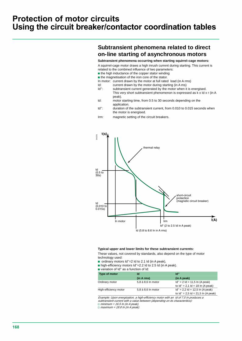
168
Protection of motor circuitsUsing the circuit breaker/contactor coordination tables
Subtransient phenomena related to directon-line starting of asynchronous motorsSubtransient phenomena occurring when starting squirrel-cage motors:A squirrel-cage motor draws a high inrush current during starting. This current isrelated to the combined influence of two parameters:c the high inductance of the copper stator windingc the magnetisation of the iron core of the stator.In motor: current drawn by the motor at full rated load (in A rms)Id: current drawn by the motor during starting (in A ms)Id’’: subtransient current generated by the motor when it is energised.
This very short subtransient phenomenon is expressed as k x Id x r (in Apeak).
td: motor starting time, from 0.5 to 30 seconds depending on theapplication.
td’’: duration of the subtransient current, from 0.010 to 0.015 seconds whenthe motor is energised.
Irm: magnetic setting of the circuit breakers.
Typical upper and lower limits for these subtransient currents:These values, not covered by standards, also depend on the type of motortechnology used:c ordinary motors Id’’=2 Id to 2.1 Id (in A peak),c high-efficiency motors Id’’=2.2 Id to 2.5 Id (in A peak).c variation of Id’’ as a function of Id:Type of motor Id Id’’
(in A rms) (in A peak)Ordinary motor 5,8 à 8,6 In motor Id’’ = 2 Id = 11,5 In (A peak)
to Id’’ = 2,1 Id = 18 In (A peak)High-efficiency motor 5,8 à 8,6 In motor Id’’ = 2,2 Id = 12,5 In (A peak)
to Id’’ = 2,5 Id = 21,5 In (A peak)
Example: Upon energisation, a high-efficiency motor with an Id of 7.5 In produces asubtransient current with a value between (depending on its characteritics):v minimum = 16.5 In (in A peak),v maximum = 18.8 In (in A peak).
E41
251

169
Protection of motor circuitsUsing the circuit breaker/contactor coordination tables
Subtransient currents and protection settings:c as illustrated in the above table, subtransient currents can be very high.If they approach their upper limits, they can trip short-cicuit protection devices(nuisance tripping)c Merlin Gerin and Telemecanique circuit breakers are rated to provide optimumshort-circuit protection for motor starters (type 2 coordination with thermal relay andcontactor)c combinations made up of Merlin Gerin circuit breakers and Telemecaniquecontactors and thermal relays are designed to allow starting of motors generatinghigh subtransient currents (up to 19 In motor peak)c the tripping of short-circuit protective devices when starting with a combinationlisted in the coordination tables means:v the limits of certain devices may be reached.v the use of the starter under type 2 coordination conditions on the given motormay lead to premature wear of one of the components of the combination.
In event of such a problem, the ratings of the starter and the associatedprotective devices must be redesigned.
Using the coordination tables for Merlin Gerin circuitbreaker and Telemecanique contactors:c Ordinary motor:The starter components can be selected directly from the coordination tables,whatever the values of the starting current (Id from 5.8 to 8.6 In) and thesubtransient current.
c High-efficiency motors with Id iiiii 7.5 In:The starter components can be selected directly from the coordination tables,whatever the values of the starting current and the subtransient current.
c High-efficiency motors with Id > 7.5 InWhen Merlin Gerin circuit breakers are used for motor currents in theneighbourhood of their rated current, they are set to provide minimum short-circuit protection at 19 In motor (A peak).There are two possibilities:c The subtransient starting current is known (indicated by the motormanufacturer) and is less than 19 In motor (A peak).In this case, the starter components can be selected directly from thecoordination tables, whatever the value of the starting current (for Id > 7.5 In).
Example: For a 110 kW 380/415 V 3-phase motor, the selected components are:NS250-MA220 / LC1-F225 / LR9-F5371.c The subtransient starting current is unknown or greater than 19 In motor(A peak).
In this case, the value used for the motor power in the coordination tables shouldbe increased by 20% to satisfy optimum starting and coordination conditions.
Example: For a 110 kW 380/415 V 3-phase motor, the selected components arethose for a motor power of 110+20%=132kW: NS400-MA320 / LC1-F265 /LR9-F5371.
Reversing starters and coordination:The starter components can be selected using the tables for direct-on-line starting.
Replace contactors LC1 by LC2.
Start-delta starting and coordination:c The components should be sized according to the current flowing in the motorwindings.c The mounting locations and connections of the various components of star-deltastarters should be selected according to the type of coordination required and theprotective devices implemented.

170
Protection of motor circuitsUsing the circuit breaker/contactor coordination tables
Start-delta starting and type 2 coordinationContactors KM1, KM2 and KM3 are sized for the line current.
The starter components are selected from the direct-on-line type 2coordination tables.Example: Consider the following case:c 55 kW motor supplied at 415 Vc star-delta startingc thermal protection built into the circuit breaker providing short-circuit protectionc short-circuit current of 45 kA at the starterc type 2 coordination.
The starter components are selected using the tablesc circuit breaker: NS160H with STR22MEc starter: LC1-F115A to be replaced by LC3-F115.

171
Protection of motor circuitsCircuit breaker/contactor coordination
5 P 10
Accuracy class (5%)
CT intended for motor protection
Multiple of the saturation current
Starting class and thermal relaysThe data in the tables corresponds to “normal” motor starting times. Theassociated thermal relays are either class 10 or 10 A (tripping time < 10 s).c for motors with long starting times, the class 10 or 10 A thermal relays must bereplaced with class 20 thermal relays as indicated in the correspondence tableopposite (for type 1 and type 2 coordination)c long starting times requiring a class 30 relay:v apply a derating coefficient (K = 0.8) to the circuit breaker and the contactor.
Example: E.g.NS100H MA 100 for 80 A maximum.LC1F115 for 92 A maximum;
c these tables may also be used for standard thermal protection usingcurrent transformers.The required thermal relays are:v LR2-D1305 (0.63 to 1 A) for class 10v LR2-D1505 (0.63 to 1 A) for class 20 with terminal block LA7-D1064.
The current transformer ratings must be 5 VA per phase. The other characteristicsare identical to those described below.c coordination tables with the multifunction protective relay LT6-Pv three types of multifunction relays (see the corresponding catalogue for detailedcharacteristics) are available. They may be connected:- directly to the motor power supply line;- to the secondary winding of the current transformer.Relay Rating Connecting
Direct Using current
transformersLT6-P0M005 FM 0,2 to 1 A c c
1 to 5 A c cLT6-P0M025 FM 5 to 25 A cv the characteristics of the current transformers are the following (as defined byIEC 44-1 / 44-3):

172
Protection of motor circuitsCircuit breaker/contactor coordination
Correspondence table for class 10/10 A and class 20 relaysThermal relay
Class 10/10 A Class 20 Setting rangeLR2-D1305 0.63 to 1LR2-D1306 1 to 1.6LR2-D1307 1.6 to 2.5LR2-D1308 LR2-D1508 2.5 to 4LR2-D1310 LR2-D1510 4 to 6LR2-D1312 LR2-D1512 5.5 to 8LR2-D1314 LR2-D1514 7 to 10LR2-D1316 LR2-D1516 9 to 13LR2-D1321 LR2-D1521 12 to 18LR2-D1322 LR2-D1522 17 to 25LR2-D2353 LR2-D2553 23 to 32LR2-D2355 28 to 36LR2-D3322 LR2-D3522 17 to 25LR2-D3353 LR2-D3553 23 to 32LR2-D3355 LR2-D3555 30 to 40LR2-D3357 LR2-D3557 37 to 50LR2-D3359 LR2-D3559 48 to 65LR2-D3361 LR2-D3561 55 to 70LR2-D3363 LR2-D3563 63 to 80LR2-D3365 80 to 93LR9-D5357 LR9-D5557 30 to 50LR9-D5363 LR9-D5563 48 to 80LR9-D5367 LR9-D5567 60 to 100LR9-D5369 LR9-D5569 90 to 150LR9-F5357 LR9-F5557 30 to 50LR9-F5363 LR9-F5563 48 to 80LR9-F5367 LR9-F5567 60 to 100LR9-F5369 LR9-F5569 90 to 150LR9-F5371 LR9-F5571 132 to 220LR9-F7375 LR9-F7575 200 to 300LR9-F7379 LR9-F7579 300 to 500LR9-F7381 LR9-F7581 380 to 630LR2-F7379 LR2-F7579 315 to 500LR2-F7381 LR2-F7581 400 to 630LR2-F8383 LR2-F7583 500 to 800LR2-F8385 LR2-F7585 630 to 1000

173
Type 2 co-ordination(IEC 60947-4-1) 220/240 V
Merlin Gerin circuit breakers,TelemecaniquecontactorsPerformance: U = 220/240 VCircuit breakers N H L
NS100-STR22ME 85 kA 100 kA 130 kANS160-STR22ME 85 kA 100 kA 130 kANS250-STR22ME 85 kA 100 kA 130 kANS400-STR43ME 85 kA 100 kA 130 kANS630-STR43ME 85 kA 100 kA 130 kA
Starting: STR22ME STR43MENormal class 10 class 10Long - class 20
Motors Circuit-breakers Contactors
P (kW) I (A) 220 V I (A) 240 V Ie max (A) Type Trip unit Irth (A) Irm (A) Type1.5 6.5 6 10 NS100 STR22ME 6/10 13 Irth LC1-D802.2 9 8 10 NS100 STR22ME 6/10 13 Irth LC1-D803 12 11 12.5 NS100 STR22ME 7.5/12.5 13 Irth LC1-D804 15 14 20 NS100 STR22ME 7.5/20 13 Irth LC1-D805.5 21 19 25 NS100 STR22ME 7.5/25 13 Irth LC1-D806.3 24 22 25 NS100 STR22ME 7.5/25 13 Irth LC1-D807.5 28 25 40 NS100 STR22ME 24/40 13 Irth LC1-D8010 36 33 40 NS100 STR22ME 24/40 13 Irth LC1-D8011 39 36 40 NS100 STR22ME 24/40 13 Irth LC1-D8015 52 48 80 NS100 STR22ME 48/80 13 Irth LC1-D8018.5 63 59 80 NS100 STR22ME 48/80 13 Irth LC1-D8022 75 70 100 NS100 STR22ME 60/100 13 Irth LC1-D115
or LC1-F115NS400 STR43ME 60/120 13 Irth LC1-F185
30 100 95 100 NS100 STR22ME 60/100 13 Irth LC1-D115or LC1-F115
NS400 STR43ME 60/120 13 Irth LC1-F18537 125 115 150 NS160 STR22ME 90/150 13 Irth LC1-D150
or LC1-F150NS400 STR43ME 100/200 13 Irth LC1-F185
45 150 140 150 NS160 STR22ME 90/150 13 Irth LC1-D150or LC1-F150
NS400 STR43ME 100/200 13 Irth LC1-F18555 180 170 185 NS250 STR22ME 131/220 13 Irth LC1-F185
NS400 STR43ME 100/200 13 Irth LC1-F18575 250 235 265 NS400 STR43ME 160/320 13 Irth LC1-F26590 300 280 320 NS400 STR43ME 160/320 13 Irth LC1-F330110 360 330 400 NS630 STR43ME 250/500 13 Irth LC1-F400132 430 400 500 NS630 STR43ME 250/500 13 Irth LC1-F500150 460 450 500 NS630 STR43ME 250/500 13 Irth LC1-F500
E62
559

174
Type 2 co-ordination(IEC 60947-4-1) 220/240 V
Merlin Gerin circuit breakers,Telemecaniquecontactors and thermal relaysPerformance: U = 220/240 VCircuit breaker N H L
NS80-MA - 100 kA -
Starting (1): normal LRD2 class 10 A, LR9 class 10
Motors Circuit breakers Contactors (2) Thermal relays
P (kW) I (A) 220 V I (A) 240 V Ie max (A) Type Cal. (A) Irm (A) Type Type Irth (1) (A)0.09 0.7 0.6 1 NS80H-MA 1.5 13.5 LC1-D09 LR2-D13 05 0.63/10.12 0.9 0.8 1 NS80H-MA 1.5 13.5 LC1-D09 LR2-D13 05 0.63/10.18 1.2 1.1 1.6 NS80H-MA 2.5 22.5 LC1-D09 LR2-D13 06 1/1.60.25 1.5 1.4 2.5 NS80H-MA 2.5 32.5 LC1-D09 LR2-D13 07 1.6/2.50.37 2 1.8 2.5 NS80H-MA 2.5 32.5 LC1-D09 LR2-D13 07 1.6/2.50.55 2.8 2.6 4 NS80H-MA 6.3 57 LC1-D18 LR2-D13 08 2.5/40.75 3.5 3.2 4 NS80H-MA 6.3 57 LC1-D18 LR2-D13 08 2.5/41.1 5 4.5 6 NS80H-MA 6.3 82 LC1-D25 LR2-D13 10 4/61.5 6.5 6 8 NS80H-MA 12.5 113 LC1-D32 LR2-D13 12 5.5/82.2 9 8 10 NS80H-MA 12.5 138 LC1-D32 LR2-D13 14 7/103 12 11 12.5 NS80H-MA 12.5 163 LC1-D32 LR2-D13 16 9/134 15 14 18 NS80H-MA 25 250 LC1-D32 LR2-D13 21 12/185.5 21 19 25 NS80H-MA 25 325 LC1-D40 LR2-D33 22 17/256.3 24 22 25 NS80H-MA 25 325 LC1-D40 LR2-D33 22 17/257.5 28 25 32 NS80H-MA 50 450 LC1-D40 LR2-D33 53 23/32
50 LC1-D80 LR9-D53 57 30/5010 36 33 40 NS80H-MA 50 550 LC1-D50 LR2-D33 55 30/40
50 LC1-D80 LR9-D53 57 30/5011 39 36 50 NS80H-MA 50 650 LC1-D50 LR2-D33 57 37/50
LC1-D80 LR9-D53 57 30/5015 52 48 63 NS80H-MA 80 880 LC1-D65 LR2-D33 59 48/65
80 LC1-D80 LR9-D53 63 48/8018.5 63 59 63 NS80H-MA 80 880 LC1-D65 LR2-D33 59 48/65
80 LC1-D80 LR9-D53 63 48/8022 75 70 80 NS80H-MA 80 1040 LC1-D80 LR2-D33 63 63/80
LC1-D80 LR9-D53 63 48/80
(1) For long starting (class 20), see the correspondence table for thermal relays, page 132.(2) Reversers: replace LC1 with LC2; star-delta starter: replace LC1 by LC3.
E34
309

175
Type 2 co-ordination(IEC 60947-4-1) 220/240 V
Motors Circuit breakers Contactors (2) Thermal relays
P (kW) I (A) 220 V I (A) 240 V Ie max (A) Type Cal. (A) Irm (A) Type Type Irth (1) (A)0.18 1.2 1.1 1.6 NS100-MA 2.5 22.5 LC1-D09 LR2-D13 06 1/1.60.25 1.5 1.4 2.5 NS100-MA 2.5 32.5 LC1-D09 LR2-D13 07 1.6/2.50.37 2 1.8 2.5 NS100-MA 2.5 32.5 LC1-D09 LR2-D13 07 1.6/2.50.55 2.8 2.6 4 NS100-MA 6.3 57 LC1-D40 LR2-D13 08 2.5/40.75 3.5 3.2 4 NS100-MA 6.3 57 LC1-D40 LR2-D13 08 2.5/41.1 5 4.5 6 NS100-MA 6.3 82 LC1-D40 LR2-D13 10 4/61.5 6.5 6 8 NS100-MA 12.5 113 LC1-D40 LR2-D13 12 5.5/82.2 9 8 10 NS100-MA 12.5 138 LC1-D40 LR2-D13 14 7/103 12 11 12.5 NS100-MA 12.5 163 LC1-D40 LR2-D13 16 9/134 15 14 18 NS100MA 25 250 LC1-D40 LR2-D13 21 12/185.5 21 19 25 NS100-MA 25 325 LC1-D40 LR2-D33 22 17/256.3 24 22 25 NS100-MA 25 325 LC1-D40 LR2-D33 22 17/257.5 28 25 32 NS100-MA 50 450 LC1-D80 LR2-D33 53 23/32
50 650 LR9-D53 57 30/5010 36 33 40 NS100-MA 50 550 LC1-D80 LR2-D33 55 30/40
50 650 LR9-D53 57 30/5011 39 36 40 NS100-MA 50 550 LC1-D80 LR2-D33 55 30/40
50 650 LR9-D53 57 30/5015 52 48 63 NS100-MA 100 700 LC1-D80 LR2-D33 59 48/65
80 1100 LR9-D53 63 48/8018.5 63 59 63 NS100-MA 100 900 LC1-D80 LR2-D33 59 48/65
80 1100 LR9-D53 63 48/8022 75 70 80 NS100-MA 100 1100 LC1-D80 LR2-D33 63 63/80
LR9-D53 63 48/8030 100 95 100 NS100-MA 100 1300 LC1-D115 LR9-D53 67 60/100
LC1-F115 LR9-F53 6737 125 115 150 NS160-MA 150 1950 LC1-D150 LR9-D53 69 90/150
LC1-F150 LR9-F53 6945 150 140 150 NS160-MA 150 1950 LC1-D150 LR9-D53 69 90/150
LC1-F150 LR9-F53 6955 180 170 185 NS250-MA 220 2420 LC1-F185 LR9-F53 71 132/220
220 NS400-MA 320 2880 LC1-F26575 250 235 265 NS400-MA 320 3500 LC1-F265 LR9-F73 75 200/33090 300 270 320 NS400-MA 320 4160 LC1-F330 LR9-F73 75 200/330110 360 330 400 NS630-MA 500 5700 LC1-F400 LR9-F73 79 300/500132 430 400 500 NS630-MA 500 6500 LC1-F500 LR9-F73 79 300/500150 460 450 500 NS630-MA 500 6500 LC1-F500 LR9-F73 79 300/500
(1) For long starting (class 20), see the correspondence table for thermal relays, page 132.(2) Reversers: replace LC1 with LC2; star-delta starter: replace LC1 by LC3.
Merlin Gerin circuit breakers,Telemecaniquecontactors and thermal relaysPerformance: U = 220/240 VCircuit breakers N H L
NS100-MA 85 kA 100 kA 130 kANS160/250-MA 85 kA 100 kA 130 kANS400/630-MA - 100 kA 130 kA
Starting (1): normal LR2 class 10 A, LR9 class 10
E34
309

176
Type 2 co-ordination(IEC 60947-4-1) 380/415 V
Merlin Gerin circuit breakers,TelemecaniquecontactorsPerformance: U = 380/415 VCircuit breakers N H L
NS100-STR22ME 25 kA 70 kA 130 kANS160-STR22ME 35 kA 70 kA 130 kANS250-STR22ME 35 kA 70 kA 130 kANS400-STR43ME 45 kA 70 kA 130 kANS630-STR43ME 45 kA 70 kA 130 kA
Starting: standard IEC 60947-4-1 , type 2STR22ME STR43ME Micrologic 5.0
Normal class 10 class 10 class 10Long - class 20 class 20
Motors Circuit breakers Contactors (2)
P(kW) I(A) 380V I(A) 415V Ie max Type Trip unit/t.u. Irth(A) Irm(A) Type7.5 16 14 20 NS100 STR22ME 12/20 13Irth LC1-D8010 21 19 25 NS100 STR22ME 15/25 13Irth LC1-D8011 23 21 25 NS100 STR22ME 15/25 13Irth LC1-D8015 30 28 40 NS100 STR22ME 24/40 13Irth LC1-D8018.5 37 35 40 NS100 STR22ME 24/40 13Irth LC1-D8022 44 40 50 NS100 STR22ME 30/50 13Irth LC1-D8030 60 55 80 NS100 STR22ME 48/80 13Irth LC1-D8037 72 66 80 NS100 STR22ME 48/80 13Irth LC1-D8045 85 80 100 NS100 STR22ME 60/100 13Irth LC1-D115 or LC1-F115
NS400 STR43ME 60/120 13Irth LC1-F18555 105 100 115 NS160 STR22ME 90/150 13Irth LC1-D115 or LC1-F115
NS400 STR43ME 60/120 13Irth LC1-F18575 138 135 150 NS160 STR22ME 90/150 13Irth LC1-D150 or LC1-F150
NS400 STR43ME 100/200 13Irth LC1-F18590 170 165 185 NS250 STR22ME 131/220 13Irth LC1-F185
NS400 STR43ME 100/200 13Irth LC1-F185110 205 200 220 NS250 STR22ME 131/220 13Irth LC1-F225
NS400 STR43ME 160/200 13Irth LC1-F225132 250 240 265 NS400 STR43ME 160/320 13Irth LC1-F265160 300 280 320 NS400 STR43ME 160/320 13Irth LC1-F330200 370 340 400 NS630 STR43ME 250/500 13Irth LC1-F400220 408 385 500 NS630 STR43ME 250/500 13Irth LC1-F500250 460 425 500 NS630 STR43ME 250/500 13Irth LC1-F500
(2) Reversers: replace LC1 with LC2; star-delta starter: replace LC1 by LC3.
E62
559

177
Type 2 co-ordination(IEC 60947-4-1) 380/415 V
Motors Circuit breakers Contactors (2) Thermal relays
P (kW) I (A) 380 V I (A) 415 V Ie max (A) Type Cal. (A) Irm (A) Type Type Irth (1) (A)0.18 0.7 0.6 1 NS80H-MA 1.5 13.5 LC1-D09 LR2-D13 05 0.63/10.25 0.9 0.8 1 NS80H-MA 1.5 13.5 LC1-D09 LR2-D13 05 0.63/10.37 1.2 1.1 1.6 NS80H-MA 2.5 22.5 LC1-D09 LR2-D13 06 1/1.60.55 1.6 1.5 2.5 NS80H-MA 2.5 32.5 LC1-D09 LR2-D13 07 1.6/2.50.75 2 1.8 2.5 NS80H-MA 2.5 32.5 LC1-D09 LR2-D13 07 1.6/2.51.1 2.8 2.6 4 NS80H-MA 6.3 57 LC1-D18 LR2-D13 08 2.5/41.5 3.7 3.4 4 NS80H-MA 6.3 57 LC1-D18 LR2-D13 08 2.5/42.2 5.3 4.8 6 NS80H-MA 6.3 82 LC1-D25 LR2-D13 10 4/63 7 6.5 8 NS80H-MA 12.5 113 LC1-D32 LR2-D13 12 5.5/84 9 8.2 10 NS80H-MA 12.5 138 LC1-D32 LR2-D13 14 7/105.5 12 11 12.5 NS80H-MA 12.5 163 LC1-D32 LR2-D13 16 9/137.5 16 14 18 NS80H-MA 25 250 LC1-D32 LR2-D13 21 12/1810 21 19 25 NS80H-MA 25 325 LC1-D40 LR2-D33 22 17/2511 23 21 25 NS80H-MA 25 325 LC1-D40 LR2-D33 22 17/2515 30 28 32 NS80H-MA 50 450 LC1-D40 LR2-D33 53 23/32
LC1-D80 LR9-D53 57 30/5018.5 37 34 40 NS80H-MA 50 550 LC1-D50 LR2-D33 55 30/40
LC1-D80 LR9-D53 57 30/5022 43 40 50 NS80H-MA 50 650 LC1-D50 LR2-D33 57 37/50
LC1-D80 LR9-D53 57 30/5030 59 55 63 NS80H-MA 80 880 LC1-D65 LR2-D33 59 48/65
LC1-D80 LR9-D53 63 48/8037 72 66 80 NS80H-MA 80 1040 LC1-D80 LR2-D33 63 63/80
LC1-D80 LR9-D53 63 48/80
(1) For long starting (class 20), see the correspondence table for thermal relays.(2) Reversers: replace LC1 with LC2; star-delta starter: replace LC1 by LC3.
E34
309
Merlin Gerin circuit breakers,Telemecaniquecontactors and thermal relaysPerformance: U = 380/415 VCircuit breaker N H L
NS80-MA _ 70 kA -
Starting (1): normal LR2 class 10 A, LR9 class 10

178
Type 2 co-ordination(IEC 60947-4-1) 380/415 V
Merlin Gerin circuit breakers,Telemecaniquecontactors and thermal relaysPerformance: U = 380/415 VCircuit breakers N H L
NS100-MA 25 kA 70 kA 130 kANS160/250-MA 35 kA 70 kA 130 kANS400/630-MA - 70 kA 130 kA
Starting (1): normal LRD2 class 10 A, autres class 10
Motors Circuit breakers Contactors (2) Thermal relays
P(kW) I(A) 380V I(A) 415V Ie max Type Cal. (A) Irm(A) Type Type Irth (1)0.37 1.2 1.1 1.6 NS100-MA 2.5 22.5 LC1-D09 LR2D13 06 1/1.60.55 1.6 1.5 2.5 NS100-MA 2.5 32.5 LC1-D09 LR2-D13 07 1.6/2.50.75 2 1.8 2.5 NS100-MA 2.5 32.5 LC1-D09 LR2-D13 07 1.6/2.51.1 2.8 2.6 4 NS100-MA 6.3 57 LC1-D40 LR2-D13 08 2.5/41.5 3.7 3.4 4 NS100-MA 6.3 57 LC1-D40 LR2-D13 08 2.5/42.2 5.3 4.8 6 NS100-MA 6.3 82 LC1-D40 LR2-D13 10 4/63 7 6.5 8 NS100-MA 12.5 113 LC1-D40 LR2-D13 12 5.5/84 9 8.2 10 NS100-MA 12.5 138 LC1-D40 LR2-D13 14 7 /105.5 12 11 12.5 NS100-MA 12.5 163 LC1-D40 LR2-D13 16 9/137.5 16 14 18 NS100-MA 25 250 LC1-D40 LR2-D13 21 12/1810 21 19 25 NS100-MA 25 325 LC1-D40 LR2-D33 22 17/2511 23 21 25 NS100-MA 25 325 LC1-D40 LR2-D33 22 17/2515 30 28 32 NS100-MA 50 450 LC1-D80 LR2-D33 53 23/32
50 650 LR9-F53 57 30/5018.5 37 34 40 NS100-MA 50 550 LC1-D80 LR2-D33 55 30/40
50 650 LR9-F53 57 30/5022 43 40 50 NS100-MA 50 650 LC1-D80 LR2-D33 57 37/50
650 LR9-F53 57 30/5030 59 55 63 NS100-MA 100 900 LC1-D80 LR2-D33 59 48/65
80 1100 LR9-F53 63 48/8037 72 66 80 NS100-MA 100 1100 LC1-D80 LR2-D33 63 63/80
LR9-F53 63 48/8045 85 80 100 NS100-MA 100 1300 LC1-D115 LR9-D53 67 60/100
LC1-F115 LR9-F53 6755 105 100 115 NS160-MA 150 1500 LC1-D115 LR9-D53 69 90/150
LC1-F115 LR9-F53 6975 140 135 150 NS160-MA 150 1950 LC1-D150 LR9-D53 69 90/150
LC1-F150 LR9-F53 6990 170 160 185 NS250-MA 220 2420 LC1-F185 LR9-F53 71 132/220110 210 200 220 NS250-MA 220 2860 LC1-F225 LR9-F53 71 132/220
NS400-MA 320 2880 LC1-F265132 250 230 265 NS400-MA 320 3500 LC1-F265 LR9-F73 75 200/330160 300 270 320 NS400-MA 320 4160 LC1-F330 LR9-F73 75 200/330200 380 361 400 NS630-MA 500 5700 LC1-F400 LR9-F73 79 300/500220 420 380 500 NS630-MA 500 6500 LC1-F500 LR9-F73 79 300/500250 460 430 500 NS630-MA 500 6500 LC1-F500 LR9-F73 79 300/500
(1) For long starting (class 20), see the correspondence table for thermal relays.(2) Reversers: replace LC1 with LC2; star-delta starter: replace LC1 by LC3.
E62
560

179
Type 2 co-ordination(IEC 60947-4-1) 380/415 V
Motors Circuit breakers Contactors (2) Thermal relays
P (kW) I (A) 380 V I (A) 415 V Ie max (A) Type rating(A) Irm (A) Type Type Irth (1) (A)0.18 0.7 0.6 1 NS80H-MA 1.5 13.5 LC1-D40 LT6-POM 0.2/10.25 0.9 0.8 1 NS80H-MA 1.5 13.5 LC1-D40 LT6-POM 0.2/10.37 1.2 1.1 1.6 NS80H-MA 2.5 32.5 LC1-D40 LT6-POM 1/50.55 1.6 1.5 2.5 NS80H-MA 2.5 32.5 LC1-D40 LT6-POM 1/50.75 2 1.8 2.5 NS80H-MA 2.5 32.5 LC1-D40 LT6-POM 1/51.1 2.8 2.6 4 NS80H-MA 6.3 70 LC1-D40 LT6-POM 1/51.5 3.7 3.4 4 NS80H-MA 6.3 70 LC1-D40 LT6-POM 1/52.2 5.3 4.8 6 NS80H-MA 6.3 82 LC1-D40 LT6-POM 5/253 7 6.5 8 NS80H-MA 12.5 163 LC1-D40 LT6-POM 5/254 9 8.2 10 NS80H-MA 12.5 163 LC1-D40 LT6-POM 5/255.5 12 11 12.5 NS80H-MA 12.5 163 LC1-D40 LT6-POM 5/257.5 16 14 18 NS80H-MA 25 325 LC1-D40 LT6-POM 5/2510 21 19 25 NS80H-MA 25 325 LC1-D40 LT6-POM 5/2511 23 21 25 NS80H-MA 25 325 LC1-D40 LT6-POM 5/2515 30 28 50 NS80H-MA 50 650 LC1-D80 LT6-POM on TC18.5 37 34 50 NS80H-MA 50 650 LC1-D80 LT6-POM on TC22 43 40 50 NS80H-MA 50 650 LC1-D80 LT6-POM on TC30 59 55 80 NS80H-MA 80 1040 LC1-D80 LT6-POM on TC37 72 66 80 NS80H-MA 80 1040 LC1-D80 LT6-POM on TC
(1) Observe the recommendations for installations with class 30 relay and mounting of the thermal relay on the current transformer.(2) Reversers: replace LC1 with LC2; star-delta starter: replace LC1 by LC3.
Merlin Gerin circuit breakers,Telemecaniquecontactors and thermal relaysPerformance: U = 380/415 VCircuit breaker N H L
NS80-MA _ 70 kA -
Starting (1): adjustable class 10A to 30

180
Type 2 co-ordination(IEC 60947-4-1) 380/415 V
Motors Circuit breakers Contactors (2)Thermal relays
P (kW) I (A) 380 V I (A) 415 V Ie max (A) Type rating(A) Irm (A) Type Type Irth (1) (A)0.37 1.2 1.1 2.5 NS100-MA 2.5 32.5 LC1-D40 LT6-POM 1/50.55 1.6 2.5 2.5 NS100-MA 2.5 32.5 LC1-D40 LT6-POM 1/50.75 2 1.8 2.5 NS100-MA 2.5 32.5 LC1-D40 LT6-POM 1/51.1 2.8 2.6 5 NS100-MA 6.3 70 LC1-D40 LT6-POM 1/51.5 3.7 3.4 5 NS100-MA 6.3 70 LC1-D40 LT6-POM 1/52.2 5.3 4.8 6.3 NS100-MA 6.3 82 LC1-D40 LT6-POM 5/253 7 6.5 12.5 NS100-MA 12.5 163 LC1-D80 LT6-POM 5/254 9 8.2 12.5 NS100-MA 12.5 163 LC1-D80 LT6-POM 5/255.5 12 11 12.5 NS100-MA 12.5 163 LC1-D80 LT6-POM 5/257.5 16 14 25 NS100-MA 25 325 LC1-D80 LT6-POM 5/2510 21 19 25 NS100-MA 25 325 LC1-D80 LT6-POM 5/2511 23 21 25 NS100-MA 25 325 LC1-D80 LT6-POM 5/2515 30 28 50 NS100-MA 50 650 LC1-D80 LT6-POM on TI18.5 37 34 50 NS100-MA 50 650 LC1-D80 LT6-POM on TI22 43 40 50 NS100-MA 50 650 LC1-D80 LT6-POM on TI30 59 55 80 NS100-MA 100 1100 LC1-D80 LT6-POM on TI37 72 66 80 NS100-MA 100 1100 LC1-D80 LT6-POM on TI45 85 80 100 NS100-MA 100 1300 LC1-D115 LT6-POM on TI
LC1-F11555 105 100 115 NS160-MA 100 1500 LC1-D115 LT6-POM on TI
LC1-F11575 140 135 150 NS160-MA 150 1950 LC1-D115 LT6-POM on TI
LC1-F11590 170 160 185 NS250-MA 220 2420 LC1-D185 LT6-POM on TI110 210 200 220 NS250-MA 220 2860 LC1-F225 LT6-POM on TI
265 NS400-MA 320 3500 LC1-F265132 250 230 265 NS400-MA 320 3500 LC1-F265 LT6-POM on TI160 300 270 320 NS400-MA 320 4000 LC1-F330 LT6-POM on TI200 380 361 400 NS630-MA 500 5700 LC1-F400 LT6-POM on TI220 420 380 500 NS630-MA 320 3500 LC1-F500 LT6-POM on TI250 460 430 500 NS630-MA 500 6300 LC1-F500 LT6-POM on TI
(1) Observe the recommendations for installations with class 30 relay and mounting of the thermal relay on the current transformer.(2) Reversers: replace LC1 with LC2; star-delta starter: replace LC1 by LC3.
Merlin Gerin circuit breakers,Telemecaniquecontactors and thermal relaysPerformance: U = 380/415 VCircuit breakers N H L
NS100-MA 25 kA 70 kA 130 kANS160/250-MA 35 kA 70 kA 130 kANS400/630-MA 70 kA 130 kA
Starting (1): adjustable class 10A to 30

181
Type 2 co-ordination(IEC 60947-4-1) 440V
Motors Circuit breakers Contactors (2)
P (kW) I (A) 440 V Ie max (A) Type Trip unit t.u. Irth (A) Irm(A) Type3 5.8 10 NS100 STR22ME 6/19 13Irth LC1-D804 8 10 NS100 STR22ME 6/19 13Irth LC1-D805.5 10.5 12.5 NS100 STR22ME 7.5/12.5 13Irth LC1-D807.5 13.7 20 NS100 STR22ME 12/20 13Irth LC1-D8010 19 25 NS100 STR22ME 15/25 13Irth LC1-D8011 20 25 NS100 STR22ME 15/25 13Irth LC1-D8015 26.5 40 NS100 STR22ME 24/40 13Irth LC1-D8018.5 33 40 NS100 STR22ME 24/40 13Irth LC1-D8022 39 40 NS100 STR22ME 24/40 13Irth LC1-D8030 51 80 NS100 STR22ME 48/80 13Irth LC1-D8037 64 80 NS100 STR22ME 48/80 13Irth LC1-D8045 76 80 NS100 STR22ME 48/80 13Irth LC1-D8055 90 100 NS100 STR22ME 60/100 13Irth LC1-D115 or LC1-F115
NS400 STR43ME 60/120 13Irth LC1-F18575 125 150 NS100 STR22ME 90/150 13Irth LC1-D150or LC1-F150
NS400 STR43ME 100/200 13Irth LC1-F18590 146 150 NS160 STR22ME 90/150 13Irth LC1-D150or LC1-F150
NS400 STR43ME 100/200 13Irth LC1-F185110 178 185 NS250 STR22ME 131/220 13Irth LC1-F185
NS400 STR43ME 100/200 13Irth LC1-F185132 215 220 NS250 STR22ME 131/220 13Irth LC1-F225
NS400 STR43ME 160/3230 13Irth LC1-F225160 256 265 NS400 STR43ME 160/320 13Irth LC1-F265200 320 320 NS400 STR43ME 160/320 13Irth LC1-F330220 353 400 NS630 STR43ME 250/500 13Irth LC1-F400250 400 400 NS630 STR43ME 250/500 13Irth LC1-F400300 460 500 NS630 STR43ME 250/500 13Irth LC1-F500
(1) Valid for 480 V NEMA(2) Reversers: replace LC1 with LC2; star-delta starter: replace LC1 by LC3.
Merlin Gerin circuit breakers,Telemecaniquecontactors and thermal relaysPerformance: U = 440 VCircuit breakers N H L
NS100-STR22ME 25 kA 65 kA 130 kANS160-STR22ME 35 kA 65 kA 130 kANS250-STR22ME 35 kA 65 kA 130 kANS400-STR22ME 42 kA 65 kA 130 kANS630-STR22ME 42 kA 65 kA 130 kA
Starting (1): standard IEC 60947-4-1, type 2 STR22ME STR43ME Micrologic 5.0
Normal class10 class10 class10
Long class20 class20

182
Type 2 co-ordination(IEC 60947-4-1) 440 V
Motors Circuit breakers Contactors (3) Thermal relays
P (kW) I (A) 440 V Ie max (A) Type Rating (A) Irm (A) Type Type Irth (1) (A)0.25 0.7 1 NS80H-MA 1.5 13.5 LC1-D09 LR2-D13 05 0.63/10.37 1 1.6 NS80H-MA 2.5 22.5 LC1-D09 LR2-D13 06 1/1.60.55 1.4 1.6 NS80H-MA 2.5 22.5 LC1-D09 LR2-D13 06 1/1.60.75 1.7 2.5 NS80H-MA 2.5 32.5 LC1-D09 LR2-D13 07 1.6/2.51.1 2.4 2.5 NS80H-MA 2.5 32.5 LC1-D09 LR2-D13 07 1.6/2.51.5 3.1 4 NS80H-MA 6.3 57 LC1-D18 LR2-D13 08 2.5/42.2 4.5 6 NS80H-MA 6.3 82 LC1-D25 LR2-D13 10 4/63 5.8 6 NS80H-MA 6.3 82 LC1-D25 LR2-D13 10 4/64 8 8 NS80H-MA 12.5 113 LC1-D32 LR2-D13 12 5.5/85.5 10.5 12.5 NS80H-MA 12.5 163 LC1-D32 LR2-D13 16 9/137.5 13.7 18 NS80H-MA 25 250 LC1-D32 LR2-D13 21 12/1810 19 25 NS80H-MA 25 325 LC1-D40 LR2-D33 22 17/2511 20 25 NS80H-MA 25 325 LC1-D40 LR2-D33 22 17/2515 26.5 32 NS80H-MA 50 450 LC1-D40 LR2-D33 53 23/3218.5 33 40 NS80H-MA 50 550 LC1-D50 LR2-D33 55 30/40
50 650 LC1-D80 LR9-D53 57 30/5022 39 40 NS80H-MA 50 550 LC1-D50 LR2-D33 55 30/40
50 650 LC1-D80 LR9-D53 57 30/5030 52 63 NS80H-MA 80 880 LC1-D65 LR2-D33 59 48/65
80 1040 LC1-D80 LR9-D53 63 48/8037 63 63 NS80H-MA 80 880 LC1-D65 LR2-D33 59 48/65
80 1040 LC1-D80 LR9-D53 63 48/8045 76 80 NS80H-MA 80 1040 LC1-D80 LR2-D3363 48/65
LR9-D53 63 48/80
(1) For long starting (class 20) see the correspondence table for thermal relays.(2) Valid for 480 V NEMA.(3) Reversers: replace LC1 with LC2; star-delta starter: replace LC1 by LC3.
Merlin Gerin circuit breakers,Telemecaniquecontactors and thermal relaysPerformance: U = 440 VCircuit breaker N H L
NS80-MA _ 65 kA -
Starting (1): normal LR2 class 10A, LR9 class 10

183
Type 2 co-ordination(IEC 60947-4-1) 440 V
Motors Circuit breakers Contactors (3) Thermal relays
P (kW) I (A) 440 V Ie max (A) Type Rating (A) Irm (A) Type Type Irth (1)0.37 1 1.6 NS100-MA 2.5 22.5 LC1-D09 LR2-D13 06 1/1.60.55 1.4 1.6 NS100-MA 2.5 22.5 LC1-D09 LR2-D13 06 1/1.60.75 1.7 2.5 NS100-MA 2.5 32.5 LC1-D09 LR2-D13 07 1.6/2.51.1 2.4 2.5 NS100-MA 2.5 32.5 LC1-D09 LR2-D13 07 1.6/2.51.5 3.1 4 NS100-MA 6.3 57 LC1-D18 LR2-D13 08 2.5/42.2 4.5 6 NS100-MA 6.3 82 LC1-D25 LR2-D13 10 4/63 5.8 6 NS100-MA 6.3 82 LC1-D25 LR2-D13 10 4/64 8 8 NS100-MA 12.5 113 LC1-D32 LR2-D13 12 5.5/85.5 10.5 12.5 NS100-MA 12.5 163 LC1-D32 LR2-D13 16 9/137.5 13.7 18 NS100-MA 25 250 LC1-D32 LR2-D13 21 12/1810 19 25 NS100-MA 25 325 LC1-D40 LR2-D33 22 17/2511 20 25 NS100-MA 25 325 LC1-D40 LR2-D33 22 17/2515 26.5 32 NS100-MA 50 450 LC1-D40 LR2-D33 53 23/3218.5 33 40 NS100-MA 50 550 LC1-D50 LR2-D33 55 30/40
50 650 LC1-D80 LR9-D53 57 30/5022 39 40 NS100-MA 50 550 LC1-D50 LR2-D33 55 30/40
50 650 LC1-D80 LR9-D53 57 30/5030 52 63 NS100-MA 100 900 LC1-D65 LR2-D33 59 48/65
80 1100 LC1-D80 LR9-D53 63 48/8037 63 63 NS100-MA 100 900 LC1-D65 LR2-D33 59 48/65
80 1100 LC1-D80 LR9-D53 63 48/8045 76 80 NS100-MA 100 1100 LC1-D80 LR2-D3363 48/65
LR9-D53 63 48/8055 90 100 NS100-MA 100 1300 LC1-D115 LR9-D53 67 60/100
LC1-F115 LR9-F53 6375 125 150 NS160-MA 150 1950 LC1-D150 LR9-D53 69 90/150
LC1-F150 LR9-F53 6990 140 150 NS160-MA 150 1950 LC1-D150 LR9-D53 69 90/150
LC1-F150 LR9-F53 69110 178 185 NS250-MA 220 2420 LC1-D185 LR9-F53 71 132/220132 210 220 NS250-MA 220 2680 LC1-D225 LR9-F53 71 132/220
265 NS400-MA 320 3500 LC1-F265160 256 265 NS400-MA 320 3500 LC1-F265 LR9-F73 75 200/330200 310 320 NS400-MA 320 4160 LC1-F330 LR9-F73 75 200/330220 353 400 NS630-MA 500 5500 LC1-F400 LR9-F73 79 300/500250 400 500 NS630-MA 500 6500 LC1-F500 LR9-F73 79 300/500300 460 500 NS630-MA 500 6500 LC1-F500 LR9-F73 79 300/500
LR2-F73 79 315/500
(1) For long starting (class 20) see the correspondence table for thermal relays.(2) Valid for 480 V NEMA.(3) Reversers: replace LC1 with LC2; star-delta starter: replace LC1 by LC3.
Merlin Gerin circuit breakers,Telemecaniquecontactors and thermal relaysPerformance: U = 440 VCircuit breaker N H L
NS100-MA 25 kA 65 kA 130 kANS160/250-MA 35 kA 65 kA 130 kANS400/630-MA 65 kA 130 kA
Starting (1): normal LR2 class 10A, LR9 class 10

184
Type 2 co-ordination(IEC 60947-4-1) 440 V
Motors Circuit breakers Contactors (3) Thermal relays
P (kW) I (A) 440 V Ie max (A) Type Rating (A) Irm (A) Type Type Irth (1) (A)0.25 0.7 1 NS80H-MA 1.5 13.5 LC1-D40 LT6-POM 0.2/10.37 1 2.5 NS80H-MA 2.5 32.5 LC1-D40 LT6-POM 1/50.55 1.4 2.5 NS80H-MA 2.5 32.5 LC1-D40 LT6-POM 1/50.75 1.7 2.5 NS80H-MA 2.5 32.5 LC1-D40 LT6-POM 1/51.1 2.4 2.5 NS80H-MA 2.5 32.5 LC1-D40 LT6-POM 1/51.5 3.1 4 NS80H-MA 6.3 82 LC1-D40 LT6-POM 1/52.2 4.5 5 NS80H-MA 6.3 82 LC1-D40 LT6-POM 1/53 5.8 6.3 NS80H-MA 6.3 82 LC1-D40 LT6-POM 5/254 8 12.5 NS80H-MA 12.5 163 LC1-D40 LT6-POM 5/255.5 10.5 12.5 NS80H-MA 12.5 163 LC1-D40 LT6-POM 5/257.5 13.7 12.5 NS80H-MA 25 325 LC1-D40 LT6-POM 5/2510 19 25 NS80H-MA 25 325 LC1-D40 LT6-POM 5/2511 20 25 NS80H-MA 25 325 LC1-D40 LT6-POM 5/2515 26.5 50 NS80H-MA 50 550 LC1-D80 LT6-POM on TC18.5 33 50 NS80H-MA 50 550 LC1-D80 LT6-POM on TC22 39 50 NS80H-MA 50 550 LC1-D80 LT6-POM on TC30 52 80 NS80H-MA 80 1040 LC1-D80 LT6-POM on TC37 63 80 NS80H-MA 80 1040 LC1-D80 LT6-POM on TC45 76 80 NS80H-MA 80 1040 LC1-D80 LT6-POM on TC
(1) Observe the recommendations for installations with a class 30 relay and mounting of the thermal relay on the current transformer.(2) Valid for 480 V NEMA.(3) Reversers: replace LC1 with LC2; star-delta starter: replace LC1 by LC3.
Merlin Gerin circuit breakers,Telemecaniquecontactors and thermal relaysPerformance: U = 440 VCircuit breaker N H L
NS80-MA - 65 kA -
Starting (1): adjustable class 10A to 30

185
Type 2 co-ordination(IEC 60947-4-1) 440 V
Motors Circuit breakers Contactors (3) Thermal relays
P (kW) I (A) 440 V Ie max (A) Type Rating (A) Irm (A) Type Type Irth (1)0.37 1 2.5 NS100-MA 2.5 32.5 LC1-D40 LR6-POM 1/50.55 1.4 2.5 NS100-MA 2.5 32.5 LC1-D40 LR6-POM 1/50.75 1.7 2.5 NS100-MA 2.5 32.5 LC1-D40 LR6-POM 1/51.1 2.4 2.5 NS100-MA 2.5 32.5 LC1-D40 LR6-POM 1/51.5 3.1 5 NS100-MA 6.3 82 LC1-D40 LR6-POM 1/52.2 4.5 5 NS100-MA 6.3 82 LC1-D40 LR6-POM 1/53 5.8 6.3 NS100-MA 6.3 82 LC1-D40 LR6-POM 5/254 8 12.5 NS100-MA 12.5 163 LC1-D80 LR6-POM 5/255.5 10.5 12.5 NS100-MA 12.5 163 LC1-D80 LR6-POM 5/257.5 13.7 25 NS100-MA 25 325 LC1-D80 LR6-POM 5/2510 19 25 NS100-MA 25 325 LC1-D80 LR6-POM 5/2511 20 25 NS100-MA 25 325 LC1-D80 LR6-POM 5/2515 26.5 50 NS100-MA 50 450 LC1-D80 LR6-POM on TI18.5 33 50 NS100-MA 50 550 LC1-D80 LR6-POM on TI22 39 50 NS100-MA 50 550 LC1-D80 LR6-POM on TI30 52 80 NS100-MA 100 1100 LC1-D80 LR6-POM on TI37 63 60 NS100-MA 100 1100 LC1-D80 LR6-POM on TI45 76 80 NS100-MA 100 1100 LC1-D80 LR6-POM on TI55 90 100 NS100-MA 100 1300 LC1-D115 LR6-POM on TI
LC1-F11575 125 150 NS160-MA 150 1950 LC1-D150 LR6-POM on TI
LC1-F15090 140 150 NS160-MA 150 1950 LC1-D150 LR6-POM on TI
LC1-F150110 178 185 NS250-MA 220 2420 LC1-D185 LR6-POM on TI132 210 220 NS250-MA 220 2680 LC1-D225 LR6-POM on TI
265 NS400-MA 320 3500 LC1-F265160 256 265 NS400-MA 320 3500 LC1-F265 LR6-POM on TI200 310 320 NS400-MA 320 4000 LC1-F330 LR6-POM on TI220 353 400 NS630-MA 500 5500 LC1-F400 LR6-POM on TI250 400 500 NS630-MA 500 6500 LC1-F500 LR6-POM on TI300 460 500 NS630-MA 500 6500 LC1-F500 LR6-POM on TI
(1) Observe the recommendations for installations with a class 30 relay and mounting of the thermal relay on the current transformer.(2) Valid for 480 V NEMA.(3) Reversers: replace LC1 with LC2; star-delta starter: replace LC1 by LC3.
Merlin Gerin circuit breakers,Telemecaniquecontactors and thermal relaysPerformance: U = 440 VCircuit breaker N H L
NS100-MA 25 kA 65 kA 130 kANS160/250-MA 35 kA 65 kA 130 kANS400/630-MA 65 kA 130 kA
Starting (1): adjustable class 10 A to 30

186
Type 2 co-ordination(IEC 60947-4-1) 500/525 V
Motors Circuit breakers Contactors (2)
P (kW) I (A) 500 V I (A) 525 V le max Type Trip unit t.u. Irth (A) Irm(A) Type4 6.5 6.5 10 NS100 STR22ME 6/10 13Irth LC1-D805.5 9 9 12.5 NS100 STR22ME 7.5/12.50 13Irth LC1-D807.5 12 12 12.5 NS100 STR22ME 7.5/12.50 13Irth LC1-D8010 15 15 20 NS100 STR22ME 12/20 13Irth LC1-D8011 18.4 18.4 20 NS100 STR22ME 6/10 13Irth LC1-D8015 23 23 25 NS100 STR22ME 24/40 13Irth LC1-D8018.5 28.5 28.5 40 NS100 STR22ME 24/40 13Irth LC1-D8022 33 33 40 NS100 STR22ME 24/40 13Irth LC1-D8030 45 45 50 NS100 STR22ME 30/50 13Irth LC1-D8037 55 55 80 NS100 STR22ME 48/80 13Irth LC1-D8045 65 65 80 NS100 STR22ME 48/80 13Irth LC1-D8055 75 75 75 NS100 STR22ME 60/100 13Irth LC1-D115 or LC1-F115
NS400 STR43ME 60/120 13Irth LC1-F18575 105 105 115 NS160 STR22ME 90/150 13Irth LC1-D150or LC1-F150
NS400 STR43ME 60/120 13Irth LC1-F18590 130 130 150 NS160 STR22ME 90/150 13Irth LC1-D150or LC1-F150
NS400 STR43ME 100/200 13Irth LC1-F185110 155 155 185 NS250 STR22ME 131/220 13Irth LC1-F185
NS400 STR400ME 100/200 13Irth LC1-F185132 185 185 220 NS250 STR22ME 131/220 13Irth LC1-F265
NS400 STR43ME 160/320 13Irth LC1-F265160 220 220 265 NS400 STR43ME 160/320 13Irth LC1-F265200 280 280 320 NS400 STR43ME 160/320 13Irth LC1-F400220 310 310 320 NS630 STR43ME 250/500 13Irth LC1-F500250 360 360 500 NS630 STR43ME 250/500 13Irth LC1-F500315 445 445 500 NS630 STR43ME 250/500 13Irth LC1-F500
(1) Reversers: replace LC1 with LC2; star-delta starter: replace LC1 by LC3.
Merlin Gerin circuit breakers,Telemecaniquecontactors and thermal relaysPerformance: U = 440 VCircuit breakers N L
NS100-STR22ME 50/35 kA 70/50 kANS160-STR22ME 50/35 kA 70/50 kANS250-STR22ME 50/35 kA 70/50 kANS400-STR43ME 50/35 kA 70/50 kANS630-STR43ME 50/35 kA 70/50 kA
Starting (1): standard IEC 60947-4-1, type 2 STR22ME STR43ME Micrologic 5.0
Normal class10 class10 class10
Long class20 class20

187
Type 2 co-ordination(IEC 60947-4-1) 500/525 V
Motors Circuit breakers Contactors (2) Thermal relays (1)
P (kW) I (A) 500 V I (A) 525 V Ie max (A) Type Rating(A) Irm (A) Type Type Irth (A)0.25 0.6 0.6 1 NS80H-MA 1.5 13.5 LC1-D09 LR2-D13 05 0.63/10.37 0.9 0.9 1 NS80H-MA 1.5 13.5 LC1-D09 LR2-D13 05 0.63/10.55 1.2 1.2 1.6 NS80H-MA 2.5 22.5 LC1-D09 LR2-D13 06 1/1.60.75 1.5 1.5 1.6 NS80H-MA 2.5 22.5 LC1-D09 LR2-D13 06 1/1.61.1 2 2 2.5 NS80H-MA 2.5 32.5 LC1-D09 LR2-D13 07 1.6/2.51.5 2.8 2.8 4 NS80H-MA 6.3 57 LC1-D18 LR2-D13 08 2.5/42.2 3.8 3.8 4 NS80H-MA 6.3 57 LC1-D18 LR2-D13 08 2.5/43 5 5 6 NS80H-MA 6.3 82 LC1-D25 LR2-D13 10 4/64 6.5 6.5 8 NS80H-MA 12.5 113 LC1-D32 LR2-D13 12 5.5/85.5 9 9 10 NS80H-MA 12.5 138 LC1-D32 LR2-D13 14 7/107.5 12 12 12.5 NS80H-MA 12.5 163 LC1-D32 LR2-D13 16 9/1310 15 15 16 NS80H-MA 25 250 LC1-D32 LR2-D33 21 12/1811 18.4 18.4 25 NS80H-MA 25 325 LC1-D40 LR2-D33 22 17/2515 23 23 25 NS80H-MA 25 325 LC1-D40 LR2-D33 22 17/2518.5 28.5 28.5 32 NS80H-MA 50 450 LC1-D40 LR2-D33 22 23/3222 33 33 40 NS80H-MA 50 550 LC1-D50 LR2-D33 55 30/40
50 650 LC1-D115 LR2-D53 57 30/50LC1-F115 LR2-F53 57 30/50
30 45 45 50 NS80H-MA 50 650 LC1-D50 LR2-D33 55 37/50LC1-D115 LR2-D53 57 30/50LC1-F115 LR2-F53 57 30/50
37 55 55 63 NS80H-MA 80 880 LC1-D65 LR2-D33 59 48/6580 1040 LC1-D115 LR2-D53 63 48/80
LC1-F115 LR2-F53 63 48/8045 65 65 80 NS80H-MA 80 1040 LC1-D115 LR2-D33 63 63/80
LC1-F115 LR2-F53 63 48/8055 75 75 80 NS80H-MA 80 1040 LC1-D115 LR2-D53 63 48/80
LC1-F115 LR2-F53 63 48/80
(1) For long starting (class 20), see the correspondence table for thermal relays.(2) Reversers: replace LC1 with LC2; star-delta starter: replace LC1 by LC3.
Merlin Gerin circuit breakers,Telemecaniquecontactors and thermal relaysPerformance: U = 500/525 VCircuit breaker H L
NS80-MA 35 kA -
Starting (1): normal LR2 class 10 A, LR9 class 10

188
Type 2 co-ordination(IEC 60947-4-1) 500/525 V
Motors Circuit breakers Contactors (2) Thermal relays
P (kW) I (A) 500 V I (A) 525 V Ie max (A) Type Rating(A) Irm (A) Type Type Irth (1) (A)0.55 1.2 1.2 1.6 NS100-MA 2.5 22.5 LC1-D09 LR2-D13 06 1/1.60.75 1.5 1.5 1.6 NS100-MA 2.5 22.5 LC1-D09 LR2-D13 06 1/1.61.1 2 2 2.5 NS100-MA 2.5 32.5 LC1-D09 LR2-D13 07 1.6/2.51.5 2.8 2.8 4 NS100-MA 6.3 57 LC1-D40 LR2-D13 08 2.5/42.2 3.8 3.8 4 NS100-MA 6.3 57 LC1-D40 LR2-D13 08 2.5/43 5 5 6 NS100-MA 6.3 82 LC1-D40 LR2-D13 10 4/64 6.5 6.5 4 NS100-MA 12.5 113 LC1-D40 LR2-D13 12 5.5/85.5 9 9 10 NS100-MA 12.5 138 LC1-D40 LR2-D13 14 7/107.5 12 12 12.5 NS100-MA 12.5 163 LC1-D40 LR2-D13 16 91310 15 15 16 NS100-MA 25 250 LC1-D40 LR2-D13 21 121811 18.4 18.4 25 NS100-MA 25 325 LC1-D80 LR2-D33 22 17/2515 23 23 25 NS100-MA 25 325 LC1-D80 LR2-D33 22 17/2518.5 28.5 28.5 32 NS100-MA 50 450 LC1-D80 LR2-D33 55 23/3222 33 33 40 NS100-MA 50 550 LC1-D80 LR2-D33 55 23/32
50 650 LC1-D115 LR2-D33 57 30/50LC1-F115 LR2-D33 57 30/50
30 45 45 50 NS100-MA 50 650 LC1-D80 LR2-D33 55 30/40LC1-D115 LR2-D33 57 30/50LC1-F115 LR2-D33 57 30/50
37 55 55 63 NS100-MA 100 900 LC1-D80 LR2-D33 59 48/6580 1100 LC1-D115 LR9-D33 63 48/80
LC1-F115 LR9-D33 63 48/8045 65 65 80 NS100-MA 100 1100 LC1-D115 LR9-D53 63 48/80
LC1-F115 LR9-D53 6355 75 75 80 NS100-MA 100 1300 LC1-D115 LR9-D53 67 60/100
LC1-F115 LR9-D53 6775 105 105 115 NS160-MA 150 1500 LC1-D115 LR9-D53 67 90/150
LC1-F115 LR9-D53 6790 130 130 150 NS160-MA 150 1950 LC1-D115 LR9-D53 69 90/150
LC1-F115 LR9-D53 69110 156 156 185 NS250-MA 220 2420 LC1-F185 LR9-D53 71 132/220132 187 187 220 NS250-MA 220 2860 LC1-F265 LR9-D53 71 132/220160 230 230 320 NS400-MA 320 4160 LC1-F400 LR9-D73 75 200/330200 280 280 320 NS400-MA 320 4160 LC1-F400 LR9-D73 75 200/330220 310 310 330 NS630-MA 500 4500 LC1-F500 LR9-D73 75 200/330250 360 360 500 NS630-MA 500 6500 LC1-F500 LR9-D73 79 300/500315 445 445 500 NS630-MA 500 6500 LC1-F500 LR9-D73 79 300/500
(1) For long starting (class 20), see the correspondence table for thermal relays./(2) Reversers: replace LC1 with LC2; star-delta starter: replace LC1 by LC3.
Merlin Gerin circuit breakers,Telemecaniquecontactors and thermal relaysPerformance: U = 380/415 VCircuit breakers H L
NS100-MA 50/35 kA 70/50 kANS160/250-MA 50/35 kA 70/50 kANS400/630-MA 50/35 kA 70/50 kA
Starting (1): normal LRD2 class 10 A, to class 10

189
Type 2 co-ordination(IEC 60947-4-1) 690 V
Motors Circuit breakers Contactors (2)
P (kW) I (A) 440 V Ie max (A) Type Trip unit t.u. Irth (A) Irm(A) Type5.5 6.6 10 NS100L STR22ME 6/10 13Irth LC1-D807.5 8.9 10 NS100L STR22ME 6/10 13Irth LC1-D8010 11.5 13 NS100L STR22ME 7.5/12.5 13Irth LC1-D8015 17 18 NS100L STR22ME 12/20 13Irth LC1-D8018.5 20.2 25 NS100L STR22ME 12/20 13Irth LC1-D8022 24.2 40 NS100L STR22ME 24/40 13Irth LC1-D8030 33 50 NS100L STR22ME 30/50 13Irth LC1-D8037 40 50 NS100L STR22ME 30/50 13Irth LC1-D8045 47 50 NS100L STR22ME 30/50 13Irth LC1-D8055 58 63 NS100L STR22ME 48/80 13Irth LC1-F11575 76 80 NS100L STR22ME 60/100 13Irth LC1F-115
165 NS400L STR43ME 60/120 13Irth LC1F-26590 94 165 NS400L STR43ME 60/120 13Irth LC1F-265110 113 165 NS400L STR43ME 100/200 13Irth LC1F-265132 135 165 NS400L STR43ME 100/120 13Irth LC1F-265160 165 165 NS400L STR43ME 100/120 13Irth LC1F-265200 203 230 NS400L STR43ME 160/320 13Irth LC1F-330220 224 230 NS400L STR43ME 160/320 13Irth LC1F-330250 253 280 NS400L STR43ME 100/320 13Irth LC1F-400
(1) Reversers: replace LC1 with LC2; star-delta starter: replace LC1 by LC3.
Merlin Gerin circuit breakers,Telemecaniquecontactors and thermal relaysPerformance: U = 690VCircuit breakers L
NS100-STR22ME 75 kANS400-STR22ME 75kA
Starting (1): standard IEC 60947-4-1, type 2 STR22ME STR43ME
Normal class10 class10
Long class20

190
Type 2 co-ordination(IEC 60947-4-1) 690 V
Motors Circuit breakers Contactors (3) Thermal relays
P (kW) I (A) 440 V Ie max (A) Type Rating (A) Irm (A) Type Type Irth (1)0.75 1.2 1.6 NS100L-MA 2.5 22.5 LC1-D09 LR2-D13 06 1/1.61 1.5 2 NS100L-MA 2.5 27.5 LC1-D09 LR2-D13 06 1.25/21.5 2 2.5 NS100L-MA 2.5 325 LC1-D09 LR2-D13 07 1.6/2.52.2 2.8 4 NS100L-MA 6.3 57 LC1-D40 LR2-D13 08 2.5/43 3.8 4 NS100L-MA 6.3 57 LC1-D40 LR2-D13 08 2.5/44 4.9 6 NS100L-MA 6.3 82 LC1-D40 LR2-D13 10 4/65.5 6.6 8 NS100L-MA 12.5 113 LC1-D80 LR2-D13 12 5.5/87.5 8.9 10 NS100L-MA 12.5 138 LC1-D80 LR2-D13 14 7/1010 11.5 13 NS100L-MA 25 175 LC1-D80 LR2-D13 16 9/1315 17 18 NS100L-MA 25 250 LC1-D80 LR2-D13 21 12/1818.5 20.5 25 NS100L-MA 25 325 LC1-D80 LR2-D13 22 17/2522 24.2 18 NS100L-MA 25 325 LC1-D80 LR2-D13 22 17/2530 33 50 NS100L-MA 50 650 LC1-D80 LR9-D53 57 30/5037 40 50 NS100L-MA 50 650 LC1-D80 LR9-D53 57 30/5045 47 50 NS100L-MA 50 650 LC1-D80 LR9-D53 57 30/5055 58 80 NS100L-MA 100 1100 LC1F-115 LR9-D53 63 48/8075 76 80 NS100L-MA 100 1100 LC1F-115 LR9-D53 63 48/8090 94 100 NS400L-MA 320 2880 LC1F-265 LR9-D53 67 60/100110 113 150 NS400L-MA 320 2880 LC1F-265 LR9-D53 69 90/150132 135 150 NS400L-MA 320 2880 LC1F-265 LR9-D53 69 90/150160 165 165 NS400L-MA 320 2880 LC1F-265 LR9-D53 71 132/220200 203 230 NS400L-MA 320 2880 LC1F-330 LR9-F73 75 200/330220 224 230 NS400L-MA 320 2880 LC1F-330 LR9-F73 75 200/330250 253 280 NS400L-MA 320 3520 LC1F-400 LR9-F73 75 200/330
(1) For long starting (class 20) see the correspondence table for thermal relays.(2) Reversers: replace LC1 with LC2; star-delta starter: replace LC1 by LC3.
Merlin Gerin circuit breakers,Telemecaniquecontactors and thermal relaysPerformance: U = 690 VCircuit breaker L
NS100L-MA 75 kANS400L-MA 75 kA
Starting (1): normal LRD2 class 10A, to class 10

191
c the electrodynamic withstand of thebusbar trunking:The peak current I limited by the circuitbreaker must be less than theelectrodynamic withstand capacity (or ratedpeak current) of the busbar trunking.
Coordination tablesThe tables for coordinating Merlin Gerin
Traditional circuit breakerselection methodThe circuit breaker used to protect adistribution circuit is chosen according to twofundamental criteria:c the maximum load current Ib flowing in thesupply circuit;c the prospective short-circuit current Isc ata point where the circuit breaker is to beinstalled.The circuit breaker is choosen such that:v In circuit breaker u Ib,v breaking capacity of the circuit breakeru Isc.
Installation example Application for Compact NSrange
Ib = 140 A
Ib = 360 A
CB1
CB2
Isc = 65 kA
Isc = 65 kA
CB1 = NS400H(Breakingcapacity = 70 kA)
CB2 = NS160H(Breakingcapacity = 70 kA)
When chosing a circuit breaker to protect abusbar trunking system, it is necessary totake into account:c the usual rules concerning the circuitbreaker current settings:Ib i Ir i Inc whereIb = maximum load currentIr = circuit breaker current settingInc = current rating of the busbar trunking
Multi 9, Compact, Compact CM andMasterpact circuit breakers with respect toTelemecanique Canalis busbar trunkinggive directly, for the different types oftrunking and circuit breakers, the maximumshort-circuit current for which the trunkingis protected.
ExampleConsider two 630 kVA/400 V transformer(Usc 4 %) supplying a main LV switchboardfor which the prospective short-circuitcurrent on the busbars is 44 kA.From the switchboard, a 30-metre longCanalis KVA63 transmission busbartrunking system (630A) supplies a CanalisKSA63 trunking system (630A) fordistribution with high-density tap-offs.A tap-off on the KSA63 trunking supplies aCanalis KSA16 trunking system.The short-circuit level are respectively:c 44 kA downstream of circuit-breaker CB1and at the upstream connection of theKVA63 trunking.c 33 kA at the junction between the KVA63transmission trunking and the KSA63trunking for high-density tap-offs.
What circuit breakers should be chosenfor CB1 and CB2 to protect theinstallation against short-circuits ?
CB1 CB2prospective Isc 44 kA 33 kAcircuit breakers NS630N (45 kA breaking NS160N (35 kA breaking
capacity) capacity)Isc protection level for KVA63 45 kAtrunkingIsc protection level for KVA63 45 kAtrunkingIsc protection level for KSA16 35 kAtrunking
LV mainswichboard
630 kVA400 V
prospective Isc44 kA
prospective Isc33 kA
Canalis KSA 63
Canalis KSA
a 30-metre KVA63transmission BBTsystems
630 kVA400 V
CB1
CB2
prospective Isc44 kA
Coordination tables between Merlin Gerin circuit breakersand Telemecanique Canalis busbar trunking

192
the different types of Telemecanique busbar trunkingType of busbar trunking Low power Medium power High powerBusbar trunking for transmission KVA 200 to 800 A KTA 1000 to 4000 Aand distribution with low-density KVC 200 to 800 A KTC 1000 to 4000 Atap-offs (380/415 V - 660/690 V) (380/415 V - 660/690 V)Busbar trunking for distribution KN 40 to 100 A KSA 100 to 800 A KHF 1000 to 4500 Awith high-density tap-offs (380/415 V) (380/415 V - 660/690 V) (380/415 V - 660/690 V)Busbar trunking for lighting KLE, KBA, KBBdistribution and management
type of Canalis busbar trunking KSA-10 KSA-16 KSA-25 KSA-40 KSA-50 KSA-63 KSA-80trunking rating (in A at 35°C) 100 160 250 400 500 630 800type of circuit breaker Compact NS100N 25 25Isc max. in kA ms. NS100H 25 70
NS100L 25 90NS160N 20 36 36NS160H 20 70 70NS160L 20 70 150NS250N 17 36 36NS250H 17 55 70NS250L 17 55 150NS400N 30 45 45NS400H 30 45 70NS400L 30 45 150NS630N 30 45 45 45 45NS630H 30 70 70 70 70NS630L 30 150 150 150 150C801N 26 30 40 50C801H 26 30 40 50C801L 30 40 55 80C1001N 40 50C1001H 40 50C1001L 55 80C1251N 50C1251H 50CMN 24 26 32 38
Masterpact M08H1 24 26 32 38M10H1 24 26 32 38M12H1 24 26 32 38M08H2 24 26 32 38M10H2 24 26 32 38M12H2 24 26 32 38M08L1 24 32 40 50M10L1 24 32 40 50M12L1 24 32 40 50
Masterpact NW NW08H1 24 26 32 38NW10H1 24 26 32 38NW12H1 24 26 32 38NW08H2 24 26 32 38NW10H2 24 26 32 38NW12H2 24 26 32 38NW08L1 24 26 32 38NW10L1 24 26 32 38NW12L1 24 26 32 38
type of Canalis busbar trunking KLE-16/20 KBA-25 KBB-25 KBA-40 KBB-40 KN-04 KN-06 KN-10trunking rating (in A at 35°C) 16/20 25 25 40 40 40 63 100type of circuit breaker Multi 9 C60H16/20 15Isc max. in kA ms.
C60H25 15 15C60L25 25 25NC100LH25 50 50C60H40 15 15 15NC100LH40 50 50 50C60H63 15NC100LH63 50NS100N (1) 25 25 25NS100H (1) 25 25 25NS100L (1) 25 25 25
(1) TM-D trip unit, rating 40 or 63 or 100 A and STR22SE rating 40 or 100 A
Coordination tables between Merlin Gerin circuit breakers and Telemecanique Canalisbusbar trunkingVoltage : 380/415 V
Coordination tables between Merlin Gerin circuit breakersand Telemecanique Canalis busbar trunking systems (cont.)

193
Coordination tables between Merlin Gerin circuit breakersand Telemecanique Canalis busbar trunking systems (cont.)
voltage : 380/415 Vtype of Canalis busbar trunking KVA-20 KVA-20 KVA-31 KVA-40 KVA-50 KVA-63 KVA-80trunking rating (in A at 35°C) 200 315 400 500 630 800type of circuit breaker Compact NS250N 36 36Isc max. in kA ms. NS250H 70 70
NS250L 100 100NS400N 35 45 45 45 45 45NS400H 35 70 70 70 70 70NS400L 35 150 150 150 150 150NS630N 45 45 45 45NS630H 70 70 70 70NS630L 150 150 150 150C801N 40 50C801H 40 60C801L 70 110C1001N 40 50C1001H 40 60
Masterpact M08H1 33 40M10H1 33 40M08H2 33 40M10H2 33 40M08L1 40 55M10L1 40 55
Masterpact NW NW08N1 29 35NW10N1 29 35NW08H1 29 35NW10H1 29 35NW08H2 29 35NW10H2 29 35NW08L1 29 35NW10L1 29 35
type of Canalis busbar trunking KVC-20 KVC-31 KVC-40 KVC-63 KVC-80trunking rating (in A at 35°C) 200 315 400 630 800type of circuit breaker Compact NS250N 35Isc max. in kA ms. NS250H 70
NS250L 100NS400N 35 45 45 45NS400H 35 70 70 70NS400L 35 150 150 150NS630N 45 45 45NS630H 70 70 70NS630L 150 150 150C801N 40 50C801H 40 60C801L 70 110C1001N 40 50C1001H 40 60C1001L 70 110
Masterpact M08H1 36 40M10H1 36 40M08H2 36 40M10H2 36 40M08L1 40 55M10L1 40 55
Masterpact NW NW08N1 29 35NW10N1 29 35NW08H1 29 35NW10H1 29 35NW08H2 29 35NW10H2 29 35NW08L1 29 35NW10L1 29 35

194
type of Canalis busbar trunking KTA-10 KTA-12 KTA-16 KTA-20 KTA-25 KTA-30 KTA-40trunking rating (in A at 35°C) 1000 1200 1600 2000 2500 3000 4000type of circuit breaker Compact C1001N 50 50Isc max. in kA ms. C1001H 55 70
C1001L 100 150C1251N 50 50C1251H 55 70
Masterpact M10H1 40 50 60 65M12H1 40 50 60 65M16H1 40 50 60 65M20H1 60 73 75 75M25H1 60 73 75 75M32H1 75 75 75M40H1 75 75 75M50H1 90M10H2 40 50 60 73M12H2 40 50 60 73M16H2 40 50 60 73M20H2 60 73 80 86M25H2 60 73 80 86M32H2 80 86 90M40H2 80 86 90M50H2 90M10L1 55 85 130M12L1 55 85 130M16L1 65 105 130 130M20L1 65 105 130 130M25L1 65 105 130 130
Masterpact NW NW10H1 40 50 60 65NW12H1 40 50 60 65NW16H1 40 50 60 65 65 65NW20H1 60 65 65 65NW25H1 60 65 65 65NW32H1 65 65 65NW40H1 65 65 65NW40bH1 80 86 90NW50H1 90NW10H2 40 50 60 72NW12H2 40 50 60 72NW16H2 40 50 60 72 80 86NW20H2 60 72 80 86NW25H2 60 72 80 86NW32H2 80 86 90NW40H2 80 86 90NW40bH2 80 86 90NW50H2 90NW25H3 60 72 80 86NW32H3 80 86 90NW40H3 80 86 90NW10L1 40 55 80NW12L1 40 55 80NW16L1 80 140 150NW20L1 80 140 150 150
Coordination tables between Merlin Gerin circuit breakersand Telemecanique Canalis busbar trunking systems (cont.)
voltage : 380/415 V

195
voltage : 380/415 Vtype of Canalis busbar trunking KTC-10 KTC-13 KTC-16 KTC-20 KTC-25 KTC-30 KTC-40 KTC-50trunking rating (in A at 35°C) 1000 1350 1600 2000 2500 3000 4000 5000type of circuit breaker Compact C1001N 50 50Isc max. in kA ms. C1001H 55 70
C1001L 100 150C1251N 50 50C1251H 55 70
Masterpact M10H1 40 50 60 65M12H1 40 50 60 65M16H1 40 50 60 65M20H1 60 73 75 75M25H1 60 73 75 75M32H1 75 75 75M40H1 75 75 75M50H1 90 95M63H1 90 95M10H2 40 50 60 73M12H2 40 50 60 73M16H2 40 50 60 73M20H2 60 73 82 82M25H2 60 73 82 82M32H2 82 82 90M40H2 82 82 90M50H2 90 95M63H2 90 95M10L1 55 85 130M12L1 55 85 130M16L1 65 105 130 130 130M20L1 65 105 130 130 130M25L1 65 105 130 130 130
Masterpact NW NW10H1 40 50 60 65NW12H1 40 50 60 65NW16H1 40 50 60 65 65 65NW20H1 60 65 65 65NW25H1 60 65 65 65NW32H1 65 65 65NW40H1 65 65 65NW40bH1 80 82 90NW50H1 90 95NW63H1 90 95NW10H2 40 50 60 73NW12H2 40 50 60 73NW16H2 40 50 60 73NW20H2 60 73 82 82NW25H2 60 73 82 82NW32H2 82 82 90NW40H2 82 82 90NW40bH2 82 82 90NW50H2 90 95NW63H2 90 95NW25H3 60 73 82 82NW32H3 82 82 90NW40H3 82 90NW10L1 40 55 80NW12L1 40 55 80NW16L1 55 80 140 150 150NW20L1 55 80 140 150 150
Coordination tables between Merlin Gerin circuit breakersand Telemecanique Canalis busbar trunking systems (cont.)

196
voltage : 380/415 V
type of Canalis busbar trunking KHF KHF KHF KHF KHFtrunking rating (in A at 35°C) 1000 1200/1450 2200/2500 3000/3400 4000/4500type of circuit breaker Compact C801N 28Isc max. in kA ms. C801H 28
C801L 45C1001N 28 50C1001H 28 50C1001L 45 80C1251N 28 50C1251H 28 50CMN 28 38 70 70CMH 28 38 85 85
Masterpact M08H1 28 38M10H1 28 38M12H1 28 38M16H1 28 38 65M20H1 28 38 75 75M25H1 28 38 75 75M32H1 75 75 75M40H1 75 75 75M50H1 90 100 100M63H1 90 100 100M08H2 28 38M10H2 28 38M12H2 28 38M16H2 28 38 90M20H2 28 38 90 100M25H2 28 38 90 100M32H2 28 38 90 100 100M40H2 90 100 100M50H2 90 120 125M63H2 90 120 125M08L1 35 50M10L1 35 50M12L1 35 50M16L1 28 42 130M20L1 28 42 130 130M25L1 28 42 130 130
Masterpact NW NW08N1 28 38NW10N1 28 38NW12N1 28 38NW16N1 28 38 42NW20N1 28 38 42 42NW08H1 28 38NW10H1 28 38NW12H1 28 38NW16H1 28 38 65NW20H1 28 38 65 65NW25H1 28 38 65 65NW32H1 65 65 65NW40H1 65 65 65NW40bH1 92 100 100NW50H1 92 100 100NW63H1 92 100 100NW08H2 28 38NW10H2 28 38NW12H2 28 38NW16H2 28 38 92NW20H2 28 38 92 100NW25H2 28 38 92 100NW32H2 92 100 100NW40H2 92 100 100NW40bH2 92 117 147NW50H2 92 117 147NW63H2 92 117 147NW25H3 28 38 92 117NW32H3 92 117 147NW40H3 92 117 147NW08L1 28 38NW10L1 28 38NW12L1 28 38NW16L1 28 38 150NW20L1 28 38 150 150
Coordination tables between Merlin Gerin circuit breakersand Telemecanique Canalis busbar trunking systems (cont.)

197
Coordination tables between Merlin Gerin circuit breakersand Telemecanique Canalis busbar trunking systems (cont.)
type of Canalis busbar trunking KSA-10 KSA-16 KSA-25 KSA-40 KSA-50 KSA-63 KSA-80trunking rating (in A at 35°C) 100 160 250 400 500 630 800type of circuit breaker Compact NS100N 8 8Isc max. in kA ms. NS100H 10 10
NS100L 20 75NS160N 8 8 8NS160H 10 10 10NS160L 20 75 75NS250N 8 8 8NS250H 10 10 10NS250L 15 20 20NS400N 10 10 10NS400H 17 20 20NS400L 14 28 35NS630N 10 10 10 20NS630H 20 20 20 20NS630L 35 35 35 35C801N 25 25 25 25C801H 26 29 35 40C801L 26 30 45 60C1001N 25 25C1001H 35 40C1001L 45 60C1251N 25C1251H 40CMN 24 26 32 38
Masterpact M08H1 24 26 32 38M10H1 24 26 32 38M12H1 24 26 32 38M08H2 24 26 32 38M10H2 24 26 32 38M12H2 24 26 32 38M08L1 24 26 32 38M10L1 24 26 32 38M12L1 24 26 32 38
Masterpact NW NW08H1 24 26 32 38NW10H1 24 26 32 38NW12H1 24 26 32 38NW08H2 24 26 32 38NW10H2 24 26 32 38NW12H2 24 26 32 38NW08L1 24 26 32 38NW10L1 24 26 32 38NW12L1 24 26 32 38
type of Canalis busbar trunking KVA-20 KVA-31 KVA-40 KVA-50 KVA-63 KVA-80trunking rating (in A at 35°C) 200 315 400 500 630 800type of circuit breaker Compact NS250N 8Isc max. in kA ms. NS250H 10
NS250L 20NS400N 10 10 10 10 10NS400H 20 20 20 20 20NS400L 20 75 75 75 75NS630N 10 10 10 10NS630H 20 20 20 20NS630L 35 35 35 35C801N 33 25C801H 33 40C801L 50 60C1001N 33 25C1001H 33 40C1001L 50 60
Masterpact M08H1 33 40M10H1 33 40M08H2 33 40M10H2 33 40M08L1 33 40M10L1 33 40
Masterpact NW NW08N1 36 40NW10N1 36 40NW08H1 36 40NW10H1 36 40NW08H2 33 40NW10H2 33 40NW08L1 33 40NW10L1 33 40
voltage: 660/690 V

198
voltage: 660/690 Vtype of Canalis busbar trunking KVC-20 KVC-31 KVC-40 KVC-63 KVC-80trunking rating (in A at 35°C) 200 315 400 630 800type of circuit breaker Compact NS250N 8Isc max. in kA ms. NS250H 10
NS250L 20NS400N 10 10 10 10NS400H 20 20 20 20NS400L 20 75 75 75NS630N 10 10 10NS630H 20 20 20NS630L 35 35 35C801N 25 25C801H 36 40C801L 60 60C1001N 25 25C1001H 36 40C1001L 60 60
Masterpact M08H1 36 40M10H1 36 40M08H2 36 40M10H2 36 40M08L1 36 40M10L1 36 40
Masterpact NW NW08N1 36 40NW10N1 36 40NW08H1 36 40NW10H1 36 40NW08H2 36 40NW10H2 36 40NW08L1 36 40NW10L1 36 40
Coordination tables between Merlin Gerin circuit breakersand Telemecanique Canalis busbar trunking systems (cont.)

199
voltage: 660/690 V
Coordination tables between Merlin Gerin circuit breakersand Telemecanique Canalis busbar trunking systems (cont.)
type of Canalis busbar trunking KTA-10 KTA-12 KTA-16 KTA-20 KTA-25 KTA-30 KTA-40trunking rating (in A at 35°C) 1000 1200 1600 2000 2500 3000 4000type of circuit breaker Compact C1001N 25 25Icc maxi en kA eff. C1001H 40 40
C1001L 60 60C1251N 25 25C1251H 40 40
Masterpact M10H1 40 50 60 65M12H1 40 50 60 65M16H1 40 50 60 65M20H1 60 65 65 75M25H1 60 65 65 75M32H1 75 75 75M40H1 75 75 75M50H1 85M10H2 40 50 60 73M12H2 40 50 60 73M16H2 40 50 60 73M20H2 60 73 80 85M25H2 60 73 80 85M32H2 80 85 85M40H2 80 85 85M50H2 85M10L1 40 50 65M12L1 40 50 65M16L1 50 65 65 65M20L1 50 65 65 65M25L1 50 65 65 65
Masterpact NW NW10H1 40 50 60 65NW12H1 40 50 60 65NW16H1 40 50 60 65 65 65NW20H1 60 65 65 65NW25H1 65 65NW32H1 65 65 65NW40H1 65 65 65NW40bH1 80 86 90NW50H1 90NW10H2 40 50 60 72NW12H2 40 50 60 72NW16H2 40 50 60 72 80 86NW20H2 60 72 80 86NW25H2 60 72 80 86NW32H2 80 86 85NW40H2 80 86 85NW40bH2 80 86 90NW50H2 90NW25H3 60 72 80 86NW32H3 80 86 90NW40H3 80 86 90NW10L1 40 50 65NW12L1 40 50 65NW16L1 65 100 100NW20L1 65 100 100

200
voltage: 660/690 Vtype of Canalis busbar trunking KTC-10 KTC-13 KTC-16 KTC-20 KTC-25 KTC-30 KTC-40 KTC-50trunking rating (in A at 35 °C) 1000 1350 1600 2000 2500 3000 4000 5000type of circuit breaker Compact C1001N 25 25Isc max. in kA ms. C1001H 40 40
C1001L 60 60C1251N 25 25C1251H 40 40
Masterpact M10H1 40 50 60 65M12H1 40 50 60 65M16H1 40 50 60 65M20H1 60 65 65 75M25H1 60 65 65 75M32H1 75 75 75M40H1 75 75 75M50H1 85 85M63H1 85 85M10H2 40 50 60 73M12H2 40 50 60 73M16H2 40 50 60 73M20H2 60 73 80 82M25H2 60 73 80 82M32H2 80 82 85M40H2 80 82 85M50H2 85 85M63H2 85 85M10L1 55 65 65M12L1 55 65 65M16L1 50 65 65 65M20L1 50 65 65 65M25L1 50 65 65 65
Masterpact NW NW10H1 40 50 60 65NW12H1 40 50 60 65NW16H1 40 50 60 65NW20H1 60 65 65 65NW25H1 60 65 65 65NW32H1 65 65NW40H1 65 65 65NW40bH1 82 82 65NW50H1 90 95NW63H1 90 95NW10H2 40 50 60 73NW12H2 40 50 60 73NW16H2 40 50 60 73NW20H2 60 73 82 82NW25H2 60 73 82 82NW32H2 82 82 90NW40H2 82 82 90NW40bH2 82 82 90NW50H2 90 95NW63H2 90 95NW25H3 60 73 82 82NW32H3 82 82 90NW40H3 82 82 90NW10L1 40 50 65NW12L1 40 50 65NW16L1 50 65 100 100 100NW20L1 50 65 100 100 100
Coordination tables between Merlin Gerin circuit breakersand Telemecanique Canalis busbar trunking systems (cont.)

201
Coordination tables between Merlin Gerin circuit breakersand Telemecanique Canalis busbar trunking systems (cont.)
voltage: 660/690 Vtype of Canalis busbar trunking KHF KHF KHF KHF KHFtrunking rating (in A at 35 °C) 1000 1200/1450 2200/2500 3000/3400 4000/4500type of circuit breaker Compact C801N 28Isc max. in kA ms. C801H 28
C801L 45C1001N 28 28C1001H 28 40C1001L 30 60C1251N 28 28C1251H 28 40CMN 28 38 50 50CMH 28 38 50 50
Masterpact M08H1 28 38M10H1 28 38M12H1 28 38M16H1 28 38 65M20H1 28 38 75 75M25H1 28 38 75 75M32H1 75 75 75M40H1 75 75 75M50H1 85 85 85M63H1 85 85 85M08H2 28 38M10H2 28 38M12H2 28 38M16H2 28 38 85M20H2 28 38 85 85M25H2 28 38 85 85M32H2 28 38 85 85 85M40H2 85 85 85M50H2 85 85 85M63H2 85 85 85M08L1 28 38M10L1 28 38M12L1 28 38M16L1 28 38 65M20L1 28 38 65 65M25L1 28 38 65 65
Masterpact NW NW08H1 28 38NW10H1 28 38NW12H1 28 38NW16H1 28 38 65NW20H1 28 38 65 65NW25H1 28 38 65 65NW32H1 65 65 65NW40H1 65 65 65NW40bH1 92 100 100NW50H1 92 100 100NW63H1 92 100 100NW08H2 28 38NW10H2 28 38NW12H2 28 38NW16H2 28 38 85NW20H2 28 38 85 85NW25H2 28 38 85 85NW32H2 85 85 85NW40H2 85 85 85NW50bH2 92 100 100NW50H2 92 100 100NW63H2 92 100 100NW25H3 28 38 92 100NW32H3 92 100 100NW40H3 92 100 100NW08L1 28 38NW10L1 28 38NW12L1 28 38NW16L1 28 38 100NW20L1 28 38 100 100

202
Coordination between circuit breakers and TelemecaniqueCanalis busbar trunking systemsCascading and reinforced discrimination
CascadingThe use of a current-limiting circuit breakerupstream to reinforce the breaking capacityof a downstream circuit breaker.
PrincipleCascading
Application for Compact NS rangeCascading
DiscriminationIn the event of an electrical fault on oneoutgoing circuit, discrimination is the abilityof the electrical installation to maintain thecontinuity of electrical power supplied to theother circuits not concerned by the fault.As a general rule, cascading anddiscrimination techniques are appliedindependently.Schneider has developed an exclusivesystem to conciliate cascading anddiscrimination.This system ensures discrimination up to thereinforced breaking capacity of theassociation of circuit breakers CB1 and CB2.
PrincipleCascading and reinforced discrimination
Application for Compact NS rangeCascading and reinforced discrimination
CB2 breaking capacity Discrimination ensured up to the reinforcedbreaking capacity of CB2
Circuit breaker selection takingcoordination into account
The use of current-limiting circuit breakersmakes it possible to implement coordinationtechniques. This improves circuit breakerperformance in terms of breaking capacityand continuity of service.
Coordination techniques are described andrecognised by the following standards:c product standards BSEN 60947-2;c installation standards IEC 364,BS7671.
CB2 = NS160N(Breakingcap. = 35 kA)
CB1 = NS400H
Renforcedbreak. cap.70 kA
CB2
CB1
Isc = 65 kA
CB2
CB1
Isc = 65 kACB2 = NS160NIsc = 65 kA
CB1 = NS400H
Break. cap. +discriminationreinforced 70 kA

203
Coordination between Merlin Gerin circuit breakers andTelemecanique Canalis busbar trunking systemsCascading and reinforced discrimination (cont.)
Cascading, reinforced discrimination andreinforced protection of busbar trunkingsystems (BTS)This technique is the direct application ofcascading and discrimination techniques tothe protection of busbar trunking systems.For various upstream circuit breakers andupstream busbar trunking systems, thetables below give directly:c the level of short-circuit protection of thebusbar trunking;c the downstream circuit breaker andassociated busbar trunking;c the cascading breaking capacity of thedownstream circuit breaker;c the level of reinforced discrimination of theupstream and downstream circuit breakers;c the level of reinforced protection of thedownstream busbar trunking.
Source
Application to a Canalis distributeddistribution system:c reinforcement of the breaking capacity ofthe NS 160N (CB2) up to 70 kA;
c discrimination between CB1 and CB2
ensured up to 70 kA;c protection of Canalis KSA 16 busbartrunking up to 70 kA.
Example of a table corresponding to theabove diagram.
rated current of the upstream busbar trunking: 315 and 400 A
CB2 = NS160N
KSA16 (160 A)
70 kA
KSA40 (400 A)
CB1 = NS400H
Upstream circuit breaker NS400N NS400H NS400LAssociated trip unit STR23SE/STR53UE STR23SE/STR53UE STR23SE/STR53UEUpstream busbar trunking KSA / KVA / KVC KSA / KVA / KVC KSA / KVA / KVC
315 and 400 A 315 and 400 A 315 and 400 ALevel of protection of the 45 70 150upstream busbar trunking (kA)Downstream circuit breaker NS100N NS160N NS100N NS160N NS100H NS160HAssociated trip unit TMD/STR22SE TMD/STR22SE TMD/STR22SEDownstream busbar trunking KSA KSA KSA KSA KSA KSA
100 A 160 A 100 A 160 A 100 A 160 ADiscrimination limit betweenupstream and downstreamcircuit breakers (kA) 45 45 70 70 150 150Reinforced breaking capacityof the downstream circuitbreaker (kA) 45 45 70 70 150 150Reinforced protection ofthe downstream busbartrunking (kA) 45 45 70 70 25 70
NS400HSTR23SE/STR53UEKSA / KVA / KVC315 and 400 A70
NS100N NS160N
KSA KSA100 A 160 A
70 70
70 70
70 70

204
Coordination tables between Merlin Gerin circuit breakersand Telemecanique Canalis busbar trunking systemsCascading and reinforced discrimination (cont.)
voltage: 380/415 V
rated current of the upstream busbar trunking: 1200 and 1350 AUpstream circuit breaker C1251N C1251NAssociated trip unit STR35SE / STR55UE STR45AEUpstream busbar trunking KTA-12 / KTC-13 KTA-12 / KTC-13
1200 and 1350 A 1200 and 1350 ALevel of protection of the 50 50upstream busbar trunking (kA)Downstream circuit breaker NS100N NS160N NS250N NS400N NS630N NS100N NS160N NS250N NS400N NS630NAssociated trip unit TMD / STR22SE STR23SE / STR53UE TMD / STR22SE STR23SE / STR53UEDownstream busbar trunking KSA KSA KSA KSA / KVA / KVC KSA KSA KSA KSA / KVA / KVC
100 A 160 A 250 A 315 - 400 A 500 - 630 A 100 A 160 A 250 A 315 - 400 A 500 - 630 ADiscrimination limit betweenupstream and downstreamcircuit breakers (kA) 50 50 50 45 40 50 50 50 50 50Reinforced breaking capacityof the downstreamcircuit breaker (kA) 50 50 50 50 50 50 50 50 50 50Reinforced protection of thedownstream busbar trunking(kA) 25 50 50 50 50 25 50 50 50 50
Upstream circuit breaker C1251N C1251NAssociated trip unit STR35SE / STR55UE STR45AEUpstream busbar trunking KTA-12 / KTC-13 KTA-12 / KTC-13
1200 and 1350 A 1200 and 1350 ALevel of protection of the 50 50upstream busbar trunking (kA)Downstream circuit breaker NS100N TMD / STR22SE NS100N TMD / STR22SEAssociated trip unit 40 A 63 A 100 A 40 A 63 A 100 ADownstream busbar trunking KN KN KN KN KN KN
40 A 63 A 100 A 40 A 63 A 100 ADiscrimination limit betweenupstream and downstreamcircuit breakers (kA) 50 50 50 50 50 50Reinforced breaking capacityof the downstreamcircuit breaker (kA) 50 50 50 50 50 50Reinforced protection of thedownstream busbar trunking(kA) 50 50 50 50 50 50
upstreamcircuit-breaker
source
level of protectionof the upstreambusbar trunking
reinforced cascadingand discriminationbetween the 2 circuit-breakers
upstream busbarcanalisation
downstreamcircuit-breaker
downstreambusbar trunking
reinforced protectionof the downstreambusbar trunking

205
Coordination tables between Merlin Gerin circuit breakersand Telemecanique Canalis busbar trunking systemsCascading and reinforced discrimination (cont.)
rated current of the upstream busbar trunking: 1200 and 1350 A (cont.)
Upstream circuit breaker C1251H C1251HAssociated trip unit STR35SE / STR55UE STR45AEUpstream busbar trunking KTA-12 / KTC-13 KTA-12 / KTC-13
1200 and 1350 A 1200 and 1350 ALevel of protection of the 70 70upstream busbar trunking (kA)Downstream circuit breaker NS100N NS160N NS250N NS400N NS630N NS100N NS160N NS250N NS400N NS630NAssociated trip unit TMD / STR22SE STR23SE / STR53UE TMD / STR22SE STR23SE / STR53UEDownstream busbar trunking KSA KSA KSA KSA / KVA / KVC KSA KSA KSA KSA / KVA / KVC
100 A 160 A 250 A 315 - 400 A 500 - 630 A 100 A 160 A 250 A 315 - 400 A 500 - 630 ADiscrimination limit betweenupstream and downstreamcircuit breakers (kA) 70 70 70 45 40 70 70 70 70 70Reinforced breaking capacityof the downstreamcircuit breaker (kA) 70 70 70 70 70 70 70 70 70 70Reinforced protection of thedownstream busbar trunking(kA) 70 70 70 70 70 70 70 70 70 70
Upstream circuit breaker C1251H C1251HAssociated trip unit STR35SE / STR55UE STR45AEUpstream busbar trunking KTA-12 / KTC-13 KTA-12 / KTC-13
1200 and 1350 A 1200 and 1350 ALevel of protection of the 70 70upstream busbar trunking (kA)Downstream circuit breaker NS100N TMD / STR22SE NS100N TMD / STR22SEAssociated trip unit 40 A 63 A 100 A 40 A 63 A 100 ADownstream busbar trunking KN KN KN KN KN KN
40 A 63 A 100 A 40 A 63 A 100 ADiscrimination limit betweenupstream and downstreamcircuit breakers (kA) 70 70 70 70 70 70Reinforced breaking capacityof the downstreamcircuit breaker (kA) 70 70 70 70 70 70Reinforced protection of thedownstream busbar trunking(kA) 50 50 50 50 50 50

206
rated current of the upstream busbar trunking: 1000 AUpstream circuit breaker C1001N C1001NAssociated trip unit STR35SE / STR55UE STR45AEUpstream busbar trunking KTA-10 / KTC-10 KTA-10 / KTC-10
1000 A 1000 ALevel of protection of the 50 50upstream busbar trunking (kA)Downstream circuit breaker NS100N NS160N NS250N NS400N NS630N NS100N NS160N NS250N NS400N NS630NAssociated trip unit TMD / STR22SE STR23SE / STR53UE TMD / STR22SE STR23SE / STR53UEDownstream busbar trunking KSA KSA KSA KSA / KVA / KVC KSA KSA KSA KSA / KVA / KVC
100 A 160 A 250 A 315 - 400 A 500 - 630 A 100 A 160 A 250 A 315 - 400 A 500 - 630 ADiscrimination limit betweenupstream and downstreamcircuit breakers (kA) 50 50 50 45 40 50 50 50 50 50Reinforced breaking capacityof the downstreamcircuit breaker (kA) 50 50 50 50 50 50 50 50 50 50Reinforced protection of thedownstream busbar trunking(kA) 50 50 50 50 50 50 50 50 50 50
Upstream circuit breaker C1001N C1001NAssociated trip unit STR35SE / STR55UE STR45AEUpstream busbar trunking KTA-10 / KTC-10 KTA-10 / KTC-10
1000 A 1000 ALevel of protection of the 50 50upstream busbar trunking (kA)Downstream circuit breaker NS100N TMD / STR22SE NS100N TMD / STR22SEAssociated trip unit 40 A 63 A 100 A 40 A 63 A 100 ADownstream busbar trunking KN KN KN KN KN KN
40 A 63 A 100 A 40 A 63 A 100 ADiscrimination limit betweenupstream and downstreamcircuit breakers (kA) 50 50 50 50 50 50Reinforced breaking capacityof the downstreamcircuit breaker (kA) 50 50 50 50 50 50Reinforced protection of thedownstream busbar trunking(kA) 50 50 50 50 50 50
Upstream circuit breaker C1001H C1001HAssociated trip unit STR35SE / STR55UE STR45AEUpstream busbar trunking KTA-10 / KTC-10 KTA-10 / KTC-10
1000 A 1000 ALevel of protection of the 55 55upstream busbar trunking (kA)Downstream circuit breaker NS100N NS160N NS250N NS400N NS630N NS100N NS160N NS250N NS400N NS630NAssociated trip unit TMD / STR22SE STR23SE / STR53UE TMD / STR22SE STR23SE / STR53UEDownstream busbar trunking KSA KSA KSA KSA / KVA / KVC KSA KSA KSA KSA / KVA / KVC
100 A 160 A 250 A 315 - 400 A 500 - 630 A 100 A 160 A 250 A 315 - 400 A 500 - 630 ADiscrimination limit betweenupstream and downstreamcircuit breakers (kA) 70 70 70 45 40 70 70 70 70 70Reinforced breaking capacityof the downstreamcircuit breaker (kA) 70 70 70 70 70 70 70 70 70 70Reinforced protection of thedownstream busbar trunking(kA) 55 55 55 55 55 55 55 55 55 55
Upstream circuit breaker C1001H C1001HAssociated trip unit STR35SE / STR55UE STR45UEUpstream busbar trunking KTA-10 / KTC-10 KTA-10 / KTC-10
1000 A 1000 ALevel of protection of the 55 55upstream busbar trunking (kA)Downstream circuit breaker NS100N TMD / STR22SE NS100N TMD / STR22SEAssociated trip unit 40 A 63 A 100 A 40 A 63 A 100 ADownstream busbar trunking KN KN KN KN KN KN
40 A 63 A 100 A 40 A 63 A 100 ADiscrimination limit betweenupstream and downstreamcircuit breakers (kA) 70 70 70 70 70 70Reinforced breaking capacityof the downstreamcircuit breaker (kA) 70 70 70 70 70 70Reinforced protection of thedownstream busbar trunking(kA) 50 50 50 50 50 50
Coordination tables between Merlin Gerin circuit breakersand Telemecanique Canalis busbar trunking systemsCascading and reinforced discrimination (cont.)

207
.
.
Coordination tables between Merlin Gerin circuit breakersand Telemecanique Canalis busbar trunking systemsCascading and reinforced discrimination (cont.)
rated current of the upstream busbar trunking: 800 AUpstream circuit breaker C801N C801NAssociated trip unit STR35SE / STR55UE STR45AEUpstream busbar trunking KVA-80 / KVC-80 KVA-80 / KVC-80
800 A 800 ALevel of protection of the 50 50upstream busbar trunking (kA)Downstream circuit breaker NS100N NS160N NS250N NS400N NS100N NS160N NS250N NS400NAssociated trip unit TMD / STR22SE STR23SE / STR53UE TMD / STR22SE STR23SE / STR53UEDownstream busbar trunking KSA KSA KSA KSA / KVA / KVC KSA KSA KSA KSA / KVA / KVC
100 A 160 A 250 A 315 - 400 A 100 A 160 A 250 A 315 - 400 ADiscrimination limit betweenupstream and downstreamcircuit breakers (kA) 50 50 50 35 50 50 50 35Reinforced breaking capacityof the downstreamcircuit breaker (kA) 50 50 50 50 50 50 50 50Reinforced protection of thedownstream busbar trunking(kA) 50 50 50 50 50 50 50 50
Upstream circuit breaker C801N C801NAssociated trip unit STR35SE / STR55UE STR45AEUpstream busbar trunking KVA-80 / KVC-80 KVA-80 / KVC-80
800 A 800 ALevel of protection of the 50 50upstream busbar trunking (kA)Downstream circuit breaker NS100N TMD / STR22SE NS100N TMD / STR22SEAssociated trip unit 40 A 63 A 100 A 40 A 63 A 100 ADownstream busbar trunking KN KN KN KN KN KN
40 A 63 A 100 A 40 A 63 A 100 ADiscrimination limit betweenupstream and downstreamcircuit breakers (kA) 50 50 50 50 50 50Reinforced breaking capacityof the downstreamcircuit breaker (kA) 50 50 50 50 50 50Reinforced protection of thedownstream busbar trunking(kA) 50 50 50 50 50 50
Upstream circuit breaker C801H C801HAssociated trip unit STR35SE / STR55UE STR45AEUpstream busbar trunking KVA-80 / KVC-80 KVA-80 / KVC-80
800 A 800 ALevel of protection of the 60 60upstream busbar trunking (kA)Downstream circuit breaker NS100N NS160N NS250N NS400N NS100N NS160N NS250N NS400NAssociated trip unit TMD / STR22SE STR23SE / STR53UE TMD / STR22SE STR23SE / STR53UEDownstream busbar trunking KSA KSA KSA KSA / KVA / KVC KSA KSA KSA KSA / KVA / KVC
100 A 160 A 250 A 315 - 400 A 100 A 160 A 250 A 315 - 400 ADiscrimination limit betweenupstream and downstreamcircuit breakers (kA) 70 70 70 35 70 70 70 35Reinforced breaking capacityof the downstreamcircuit breaker (kA) 70 70 70 70 70 70 70 70Reinforced protection of thedownstream busbar trunking(kA) 60 60 60 60 60 60 60 60
Upstream circuit breaker C801H C801HAssociated trip unit STR35SE / STR55UE STR45AEUpstream busbar trunking KVA-80 / KVC-80 KVA-80 / KVC-80
800 A 800 ALevel of protection of the 60 60upstream busbar trunking (kA)Downstream circuit breaker NS100N TMD / STR22SE NS100N TMD / STR22SEAssociated trip unit 40 A 63 A 100 A 40 A 63 A 100 ADownstream busbar trunking KN KN KN KN KN KN
40 A 63 A 100 A 40 A 63 A 100 ADiscrimination limit betweenupstream and downstreamcircuit breakers (kA) 70 70 70 70 70 70Reinforced breaking capacityof the downstreamcircuit breaker (kA) 70 70 70 70 70 70Reinforced protection of thedownstream busbar trunking(kA) 50 50 50 50 50 50

208
rated current of the upstream busbar trunking: 500 and 630 AUpstream circuit breaker NS630N NS630H NS630LAssociated trip unit STR23SE/STR53UE STR23SE/STR53UE STR23SE/STR53UEUpstream busbar trunking KSA / KVA / KVC KSA / KVA / KVC KSA / KVA / KVC
500 and 630 A 500 and 630 A 500 and 630 ALevel of protection of the 45 70 150upstream busbar trunking (kA)Downstream circuit breaker NS100N NS160N NS250N NS100N NS160N NS250N NS100H NS160H NS250HAssociated trip unit TMD / STR22SE TMD / STR22SE TMD / STR22SEDownstream busbar trunking KSA KSA KSA KSA KSA KSA KSA KSA KSA
100 A 160 A 250 A 100 A 160 A 250 A 100 A 160 A 250 ADiscrimination limit betweenupstream and downstreamcircuit breakers (kA) 45 45 45 70 70 70 150 150 150Reinforced breaking capacity ofthe downstream circuit breaker (kA) 45 45 45 70 70 70 150 150 150Reinforced protection of thedownstream busbar trunking(kA) 45 45 45 70 70 70 70 70 70
Upstream circuit breaker NS630N NS630H NS630LAssociated trip unit STR23SE/STR53UE STR23SE/STR53UE STR23SE/STR53UEUpstream busbar trunking KSA / KVA / KVC KSA / KVA / KVC KSA / KVA / KVC
500 and 630 A 500 and 630 A 500 and 630 ALevel of protection of the 45 70 150upstream busbar trunking (kA)Downstream circuit breaker NS100N TMD / STR22SE NS100N TMD / STR22SE NS100N TMD / STR22SEAssociated trip unit 40 A 63 A 100 A 40 A 63 A 100 A 40 A 63 A 100 ADownstream busbar trunking KN KN KN KN KN KN KN KN KN
40 A 63 A 100 A 40 A 63 A 100 A 40 A 63 A 100 ADiscrimination limit betweenupstream and downstreamcircuit breakers (kA) 45 45 45 70 70 70 150 150 150Reinforced breaking capacity ofthe downstream circuit breaker (kA) 45 45 45 70 70 70 150 150 150Reinforced protection of thedownstream busbar trunking(kA) 45 45 45 50 50 50 50 50 50
Upstream circuit breaker NS400N NS400H NS400LAssociated trip unit STR23SE/STR53UE STR23SE/STR53UE STR23SE/STR53UEUpstream busbar trunking KSA / KVA / KVC KSA / KVA / KVC KSA / KVA / KVC
315 and 400 A 315 and 400 A 315 and 400 ALevel of protection of the 45 70 150upstream busbar trunking (kA)Downstream circuit breaker NS100N NS160N NS100N NS160N NS100H NS160HAssociated trip unit TMD / STR22SE TMD / STR22SE TMD / STR22SEDownstream busbar trunking KSA KSA KSA KSA KSA KSA
100 A 160 A 100 A 160 A 100 A 160 ADiscrimination limit betweenupstream and downstreamcircuit breakers (kA) 45 45 70 70 150 150Reinforced breaking capacity ofthe downstream circuit breaker (kA) 45 45 70 70 150 150Reinforced protection of thedownstream busbar trunking(kA) 45 45 70 70 70 70
Upstream circuit breaker NS400N NS400H NS400LAssociated trip unit STR23SE/STR53UE STR23SE/STR53UE STR23SE/STR53UEUpstream busbar trunking KSA / KVA / KVC KSA / KVA / KVC KSA / KVA / KVC
315 and 400 A 315 and 400 A 315 and 400 ALevel of protection of the 45 70 150upstream busbar trunking (kA)Downstream circuit breaker NS100N TMD / STR22SE NS100N TMD / STR22SE NS100N TMD / STR22SEAssociated trip unit 40 A 63 A 100 A 40 A 63 A 100 A 40 A 63 A 100 ADownstream busbar trunking KN KN KN KN KN KN KN KN KN
40 A 63 A 100 A 40 A 63 A 100 A 40 A 63 A 100 ADiscrimination limit betweenupstream and downstreamcircuit breakers (kA) 45 45 45 70 70 70 150 150 150Reinforced breaking capacity ofthe downstream circuit breaker (kA) 45 45 45 70 70 70 150 150 150Reinforced protection of thedownstream busbar trunking(kA) 45 45 45 50 50 50 50 50 50
rated current of the upstream busbar trunking: 315 and 400 A
Coordination tables between Merlin Gerin circuit breakersand Telemecanique Canalis busbar trunking systemsCascading and reinforced discrimination (cont.)

209
Coordination tables between Merlin Gerin circuit breakersand Telemecanique Canalis busbar trunking systemsCascading and reinforced discrimination (cont.)
rated current of the upstream busbar trunking: 200 and 250 AUpstream circuit breaker NS250N NS250H NS250LAssociated trip unit TMD / STR22SE TMD / STR22SE TMD / STR22SEUpstream busbar trunking KSA / KVA / KVC KSA / KVA / KVC KSA / KVA / KVC
200 and 250 A 200 and 250 A 200 and 250 ALevel of protection of the 36 70 150upstream busbar trunking (kA)Downstream circuit breaker NS100N NS100N NS100HAssociated trip unit TMD / STR22SE TMD / STR22SE TMD / STR22SEDownstream busbar trunking KSA-10 KSA-10 KSA-10
100 A 100 A 100 ADiscrimination limit betweenupstream and downstreamcircuit breakers (kA) 36 36 36Reinforced breaking capacityof the downstreamcircuit breaker (kA) 36 70 150Reinforced protection of thedownstream busbar trunking(kA) 36 70 70
Upstream circuit breaker NS250N NS250H NS250LAssociated trip unit TMD / STR22SE TMD / STR22SE TMD / STR22SEUpstream busbar trunking KSA / KVA / KVC KSA / KVA / KVC KSA / KVA / KVC
200 and 250 A 200 and 250 A 200 and 250 ALevel of protection of the 36 70 150upstream busbar trunking (kA)Downstream circuit breaker NS100N TMD / STR22SE NS100N TMD / STR22SE NS100N TMD / STR22SEAssociated trip unit 40 A 63 A 100 A 40 A 63 A 100 A 40 A 63 A 100 ADownstream busbar trunking KN KN KN KN KN KN KN KN KN
40 A 63 A 100 A 40 A 63 A 100 A 40 A 63 A 100 ADiscrimination limit betweenupstream and downstreamcircuit breakers (kA) 36 36 36 36 36 36 36 36 36Reinforced breaking capacityof the downstreamcircuit breaker (kA) 36 36 36 70 70 70 150 150 150Reinforced protection of thedownstream busbar trunking(kA) 36 36 36 50 50 50 50 50 50
Upstream circuit breaker NS250N NS250HAssociated trip unit TMD / STR22SE TMD / STR22SEUpstream busbar trunking KSA / KVA / KVC KSA / KVA / KVC
200 and 250 A 200 and 250 ALevel of protection of the 36 70upstream busbar trunking (kA)Downstream circuit breaker C60H C60H NC100L C60H C60H NC100L NC100LHAssociated trip unit (rating A) 16 25/40 25/40 16 25/40 25/40 25/40Downstream busbar trunking KLE KBA / KBB KBA / KBB KLE KBA / KBB KBA / KBB KBA / KBB
16 A 25 - 40 A 25 - 40 A 16 A 25 - 40 A 25 - 40 A 25 - 40 ADiscrimination limit betweenupstream and downstreamcircuit breakers (kA) 25 25 36 40 40 50 70Reinforced breaking capacityof the downstreamcircuit breaker (kA) 25 25 36 40 40 50 70Reinforced protection of thedownstream busbar trunking(kA) 25 25 36 40 40 50 50
Upstream circuit breaker NS250N NS250HAssociated trip unit TMD / STR22SE TMD / STR22SEUpstream busbar trunking KSA / KVA / KVC KSA / KVA / KVC
200 and 250 A 200 and 250 ALevel of protection of the 36 70upstream busbar trunking (kA)Downstream circuit breaker C60H C60H NC100L NC100L C60H C60H NC100L NC100L NC100LH NC100LHAssociated trip unit 40 A 63 A 40 A 63 A 40 A 63 A 40 A 63 A 40 A 63 ADownstream busbar trunking KN KN KN KN KN KN KN KN KN KN
40 A 63 A 40 A 63 A 40 A 63 A 40 A 63 A 40 A 63 ADiscrimination limit betweenupstream and downstreamcircuit breakers (kA) 25 25 36 36 40 30 50 50 70 70Reinforced breaking capacityof the downstreamcircuit breaker (kA) 25 25 36 36 40 30 50 50 70 70Reinforced protection of thedownstream busbar trunking(kA) 25 25 36 36 40 30 50 50 50 50

210
rated current of the upstream busbar trunking: 160 AUpstream circuit breaker NS160N NS160HAssociated trip unit TMD / STR22SE TMD / STR22SEUpstream busbar trunking KSA KSA
160 A 160 ALevel of protection of the 36 70upstream busbar trunking (kA)Downstream circuit breaker C60H C60H NC100L C60H C60H NC100L NC100LHAssociated trip unit (rating A) 16 25/40 25/40 16 25/40 25/40 25/40Downstream busbar trunking KLE KBA / KBB KBA / KBB KLE KBA / KBB KBA / KBB KBA / KBB
16 A 25 - 40 A 25 - 40A 16 A 25 - 40 A 25 - 40 A 25 - 40 ADiscrimination limit betweenupstream and downstreamcircuit breakers (kA) 25 25 36 40 40 50 70Reinforced breaking capacityof the downstreamcircuit breaker (kA) 25 25 36 40 40 50 70Reinforced protection of thedownstream busbar trunking(kA) 25 25 36 40 40 50 50
Upstream circuit breaker NS160N NS160HAssociated trip unit TMD / STR22SE TMD / STR22SEUpstream busbar trunking KSA KSA
160 A 160 ALevel of protection of the 36 70upstream busbar trunking (kA)Downstream circuit breaker C60H C60H NC100L NC100L C60H C60H NC100L NC100L NC100LH NC100LHAssociated trip unit 40 A 63 A 40 A 63 A 40 A 63 A 40 A 63 A 40 A 63 ADownstream busbar trunking KN KN KN KN KN KN KN KN KN KN
40 A 63 A 40 A 63 A 40 A 63 A 40 A 63 A 40 A 63 ADiscrimination limit betweenupstream and downstreamcircuit breakers (kA) 25 25 36 36 40 40 50 50 70 70Reinforced breaking capacityof the downstreamcircuit breaker (kA) 25 25 36 36 40 40 50 50 70 70Reinforced protection of thedownstream busbar trunking(kA) 25 25 36 36 40 40 50 50 50 50
Coordination tables between Merlin Gerin circuit breakersand Telemecanique Canalis busbar trunking systemsCascading and reinforced discrimination (cont.)

Merlin Gerin is one of the foremostexperts of electrical distribution productsand systems. Its comprehensive array ofextra-high, medium and low voltage productsand systems is designed to manage andprotect electrical installations, ensure safetyand provide power supply reliability andcontinuity.
Schneider Electric is the leading UK and world expert in the developmentand manufacture of products for the distribution and industrial applications ofelectricity. In the UK, Schneider Electric operates from 16 industrial andcommercial sites, with 2,500 people, and achieves an annual turnover inexcess of £270 million.
Offering a full range of products and services for panel builders, OEMs,contractors, specifiers and the electrical supply industry for commercial andindustrial applications.
Schneider Electric is committed to supporting its customers at every stage ofa project. Our 180 sales engineers, is the largest dedicated sales force in theUK electrical industry.
Our sales engineers are skilled at assessing individual requirements andcombined with the expert support of our product specialists, will develop themost effective and economical solution.
5Schneider Electric Ltd, Merlin Gerin Low Voltage Devices,Fordhouse Road, Wolverhampton WV10 9ED. Tel: 01952 209502 Fax: 01902 303366.Internet address: http://www.schneider.co.uk
ExpertiseSchneider Electric
in electrical distribution,control and automatiion
0870 608 8 608
Modicon a leading brand andmarketer of high technologyprogrammable controllers (Plcs) andmotion control systems used in industrialautomation. Its international catalogueinclude Plcs, numerical controllers,specialised programming and software,f ieldbus communication networks andinterface terminals.
Telemecanique is a UK market leaderand world expert in industrial control andautomation. It provides complete solutions,with its range of components,programmable logic controllers, variablespeed drives and communications software.In addition, it offers power distributionthrough prefabricated Canalis® busbartrunking.
Leading names in electrical distribution, control and automation
Scotland Unit 11000,Academy Business Park,Gower Street, Glasgow,G51 1PR. Email [email protected]
North West 8 Brindley Road,City Park Business Village,Cornbrook, Manchester,M16 9HQ. Email [email protected]
South West 190 Park Avenue,Aztec West, Almondsbury,Bristol, BS12 4SS.Email [email protected]
Greater London2nd floor, 408 Strand,London, WC2R 0NE.Email [email protected]
Regional product showroomsNorth Schneider Electric Ltd, 123 Jack Lane, Hunslet, Leeds, LS10 1BS.
Midlands Schneider Electric Ltd,University of Warwick Science Park, Sir William Lyons Road, Coventry, CV4 7EZ.Schneider Electric Ltd,Fordhouse Road, Wolverhampton, WV10 9ED.
Local support
nationwide on one number
Fax 0870 608 8 606
Local customer centres
MGD5032 April 2001