circuit analysis in laplace domain - …eee.guc.edu.eg/courses/electronics/elct401 electric circuits...
TRANSCRIPT
CIRCUIT ANALYSIS IN LAPLACE DOMAIN
“S” DOMAIN ANALYSIS

2
Pierre Simon Laplace (1749–1827),

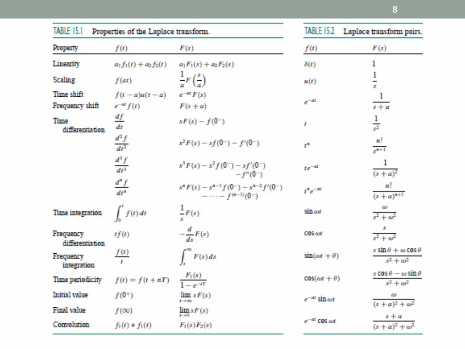
The Laplace Transform
The Laplace Transform of a function, f(t), is defined as;
0
)()()]([ dtetfsFtfLst
The Inverse Laplace Transform is defined by
j
j
tsdsesF
jtfsFL
)(2
1)()]([1
3
The Laplace Transform
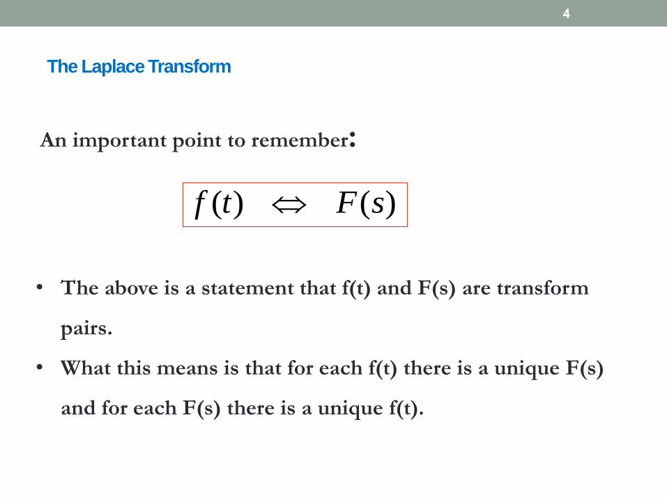
An important point to remember:
)()( sFtf
• The above is a statement that f(t) and F(s) are transform
pairs.
• What this means is that for each f(t) there is a unique F(s)
and for each F(s) there is a unique f(t).
4
The Laplace Transform
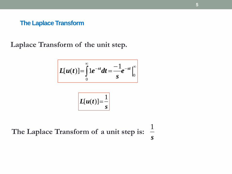
Laplace Transform of the unit step.
|0
0
11)]([
stste
sdtetuL
stuL
1)]([
The Laplace Transform of a unit step is:s
1
5

The Laplace Transform
Time Differentiation: Making the previous substitutions gives,
0
00
)()0(0
)()( |
dtetfsf
dtsetfetfdt
dfL
st
stst
So we have shown:
)0()()(
fssFdt
tdfL
6
The Laplace Transform
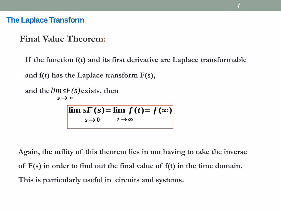
If the function f(t) and its first derivative are Laplace transformable
and f(t) has the Laplace transform F(s),
and the exists, thens
)()(lim)(lim ftfssF0s t
Again, the utility of this theorem lies in not having to take the inverse
of F(s) in order to find out the final value of f(t) in the time domain.
This is particularly useful in circuits and systems.
7
Final Value Theorem:
sF(s)lim
8
9
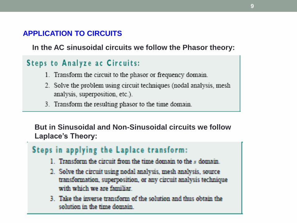
APPLICATION TO CIRCUITS
In the AC sinusoidal circuits we follow the Phasor theory:
But in Sinusoidal and Non-Sinusoidal circuits we follow
Laplace’s Theory:

Circuit Element Modeling in “S” Domain
i(t) I(s)
+_ +
_v(t) V(s)
1.0 Energy Sources
10

2.0 Resistance
Time Domain
Complex Frequency Domain
11

3.0 Inductor
di(t)
v t = LL dt
L [VL(t)] = VL(S)
Mesh-Current Model
Nodal-Analysis Model
12
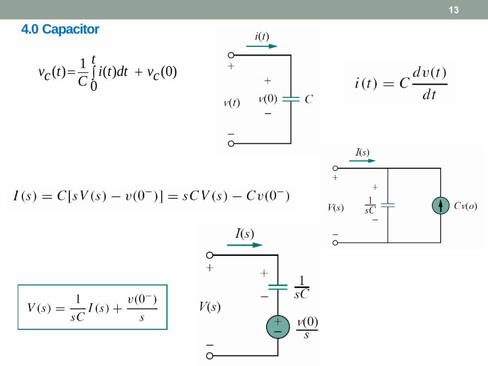
4.0 Capacitor
1( ) ( ) (0)
0
tv t i t dt vc cC
13
14
CIRCUIT ANALYSIS IN THE “S” DOMAIN

Summary
15
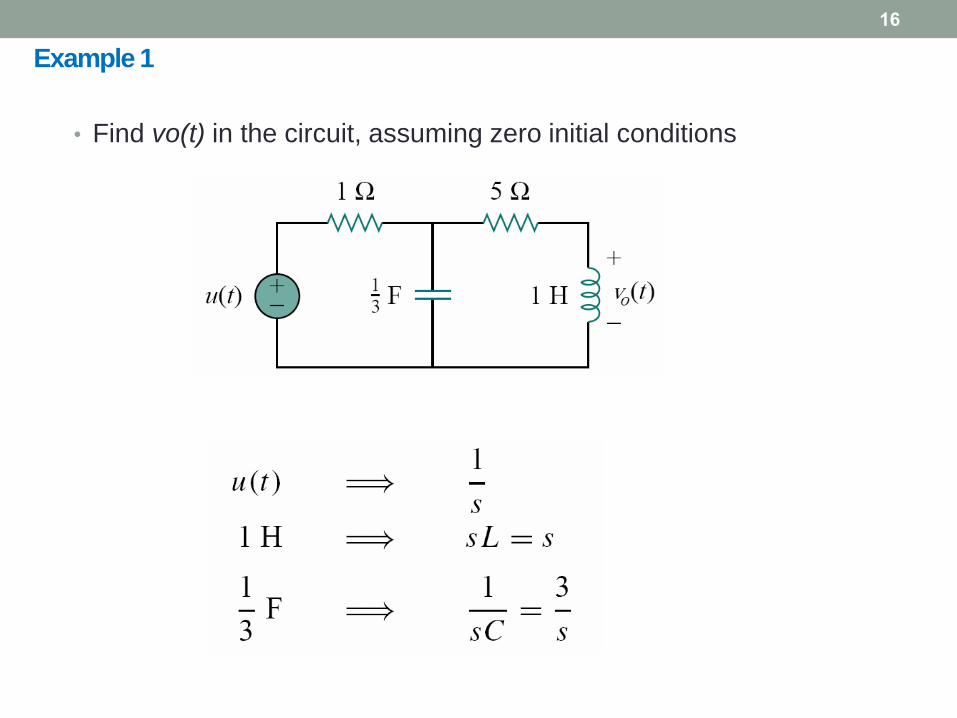
Example 1
16
• Find vo(t) in the circuit, assuming zero initial conditions
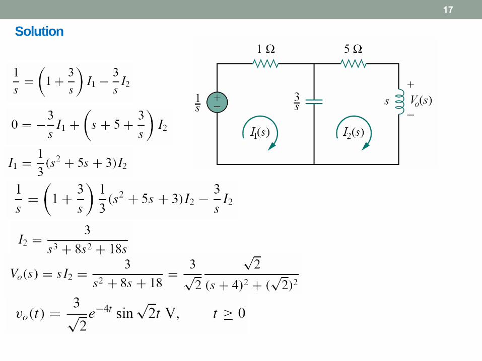
Solution
17
18
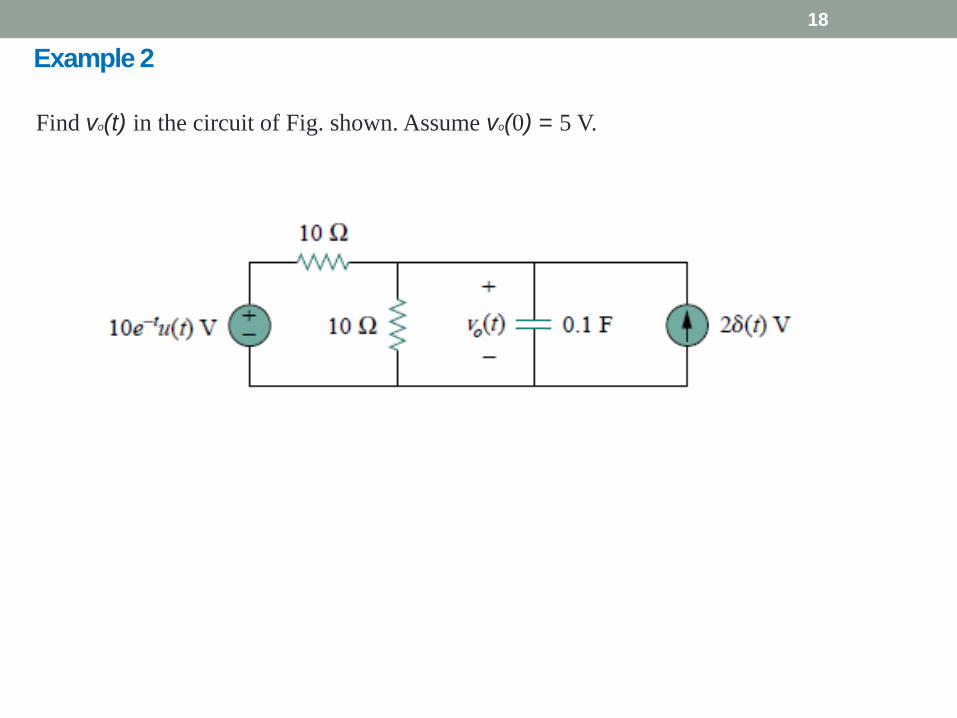
Example 2
Find vo(t) in the circuit of Fig. shown. Assume vo(0) = 5 V.

Solution
19
20
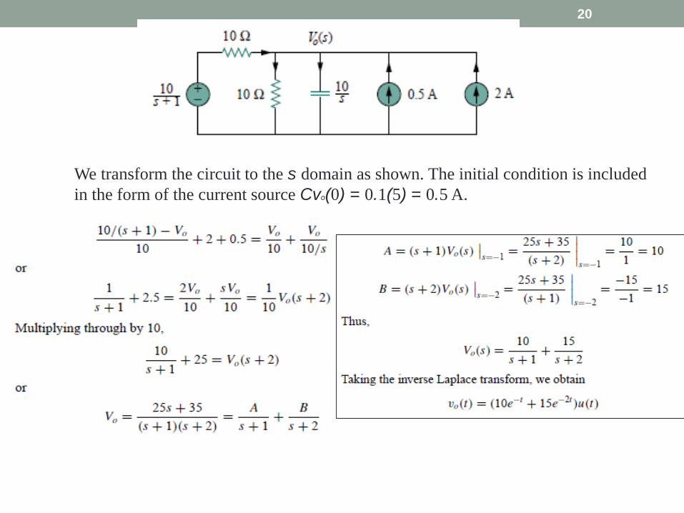
We transform the circuit to the s domain as shown. The initial condition is included
in the form of the current source Cvo(0) = 0.1(5) = 0.5 A.

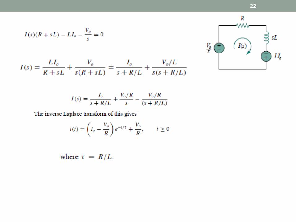
Example 3
21
In the circuit in Fig. shown, the switch moves
from position a to position b at t = 0. Find i(t)
for t > 0.
Solution
The initial current through the inductor is i(0) = Io.
For t > 0, Fig shows the circuit transformed to the s
domain. The initial condition is incorporated in the
form of a voltage source as Li(0) = LIo.
Using mesh analysis,
22
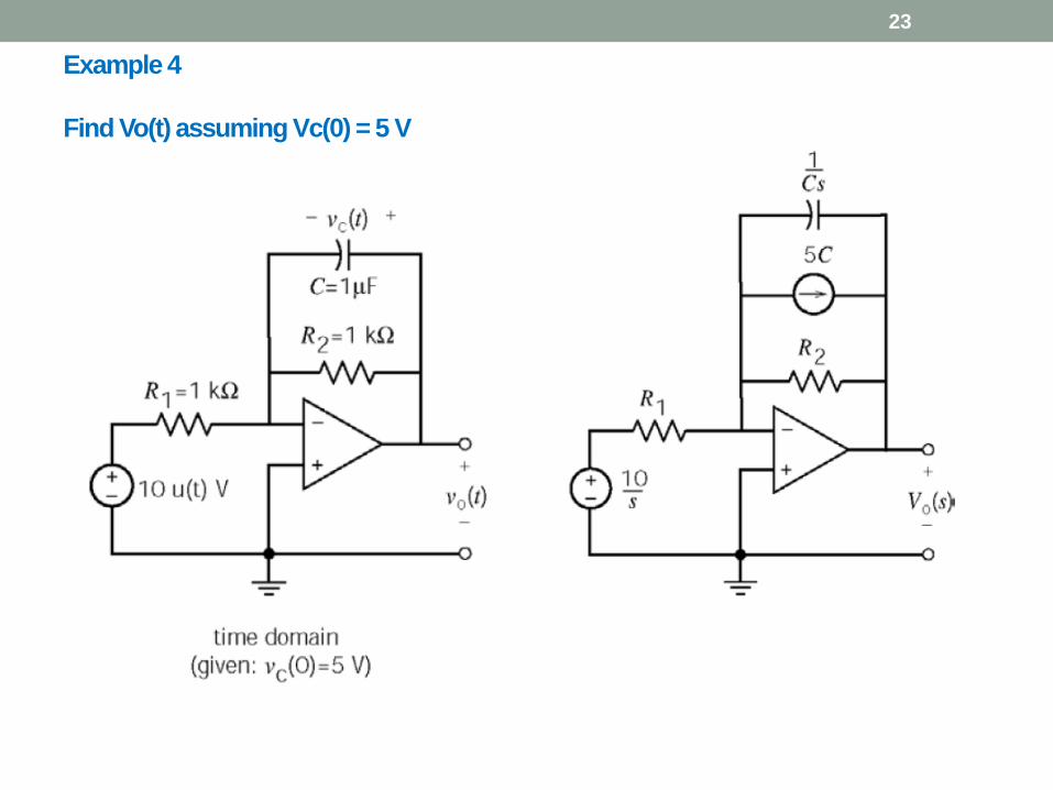
Example 4
Find Vo(t) assuming Vc(0) = 5 V
23

24
The Transfer function
25
The transfer function is a key concept in signal processing
because it indicates how a signal is processed as it passes
through a network.
It is a fitting tool for finding the network response, determining (or
designing for) network stability, and network synthesis.
The transfer function of a network describes how the output
behaves in respect to the input.
It specifies the transfer from the input to the output in the s
domain, assuming no initial energy.

The Transfer function
26
• The transfer function is also known as the network function.
There are four possible transfer
functions:

Application
27
• Determine the Transfer Function H(s) = Vo(s)/Io(s) of the circuit

Application
28
find: (a) the transfer function H(s) = Vo/Vi ,
(b) the response when vi (t) =u(t) V
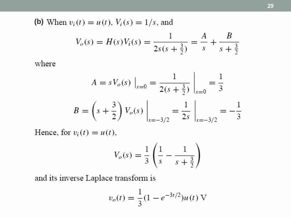
(b)
29

SINUSOIDAL FREQUENCY ANALYSIS
30
)cos(0 tB )(cos|)(|0 jHtjHB )(sH
Circuit represented by
network function

Application
31
a) Calculate the transfer function Vo/Vi
b) if Vi = 2cost(400t) V, what is the steady state
expression of Vo
solution

Good Luck
32