circle surround principles of operation
TRANSCRIPT

Circle Surround Principles of Operation
Alan Kraemer Executive Vice President, Technology
SRS Labs, Inc. Engr129.V30803

Circle Surround Principles of Operation Page 2 of 24
Confidential and Proprietary to SRS Labs, Inc. © 2003 SRS Labs, Inc.

Circle Surround Principles of Operation Page 3 of 24
Confidential and Proprietary to SRS Labs, Inc. © 2003 SRS Labs, Inc.
CONTENTS
I. OVERVIEW…………………………………………………………………………………….4
II. CIRCLE SURROUND ENCODING…………………………………………………………..5 Main, Center and LFE Encoding………………………………………………….……………...5 Surround Encoding……………………………………………………………………………….6 Encoder Bass Management……………………………………………………………………….6
III. CIRCLE SURROUND DECODING…………………………………………………………..6
Input Matrix……………………………………………………………………………………....7 Level Data Processing……………………………………………………………………………9
Steering Generator and Audio Paths……………………………………………………………..10 Filter Time Constant Generator………………………………………………………………….10 Front Channel Steering………………………………………………………………………….11 Front Audio Path………………………………………………………………………………...12 Rear Channel Steering…………………………………………………………………………..13 Rear Audio Path…………………………………………………………………………………15
IV. PRE AND POST PROCESSING……………………………………………………………...16 V. Monaural Input to Surround……………………………………………………………………17
Dialog Enhancement……………………………………………………………………………..17 Virtual Bass Enhancement……………………………………………………………………….18
VI. APPLICATIONS………………………………………………………………………………18
VII. APPENDIX……………………………………………………………………………………19
Differences Between Professional and Consumer Circle Surround II Decoders………………..19

Circle Surround Principles of Operation Page 4 of 24
Confidential and Proprietary to SRS Labs, Inc. © 2003 SRS Labs, Inc.
I. OVERVIEW
SRS Labs’ Circle Surround® (CS) technology is an advanced, highly versatile, patented multichannel audio encode and decode system capable of supporting a wide range of surround sound creation and playback applications. Circle Surround encoding provides the capability to encode up to 6.1 channels of audio for transmission or storage over two output channels or standard two-channel carriers. It is backward compatible with most matrix decoders, such as Dolby Pro Logic® and Dolby Pro Logic II, with playback performance subject to the limitations of the specific decoder. Circle Surround decoding is capable of delivering up to 5.1 channels of audio from stereo, matrix encoded or Circle Surround encoded material, while its successor, Circle Surround II, is an even more versatile multichannel decoder algorithm capable of delivering up to 6.1 multichannel audio from mono, stereo, matrix encoded or Circle Surround encoded source material. Circle Surround II features patented post processing techniques to enhance the multichannel audio experience and to address problems that occur when playing back material mixed for cinema. Even in the finest home theater environments, dialog can often become difficult to understand. SRS Labs’ Dialog Clarity™ solves this problem and significantly improves dialog intelligibility from all source material. CS II decoding also incorporates TruBass® technology to compensate for the use of small speakers or subwoofers. TruBass utilizes proprietary psychoacoustic techniques to restore the perception of low frequency fundamentals and enhance bass performance. This paper is organized as follows:
• Circle Surround encoding – A description of the Circle Surround encoding matrix and methodology
• Circle Surround decoding – An operational description of the Circle Surround II 6.1 channel decoder
• Decoder pre- and post- processing – An explanation of the features of Circle Surround II, including dialog and bass enhancement technologies, as well as the monaural input processor
• Applications – Suggested applications for the Circle Surround multichannel audio encode/decode system

Circle Surround Principles of Operation Page 5 of 24
Confidential and Proprietary to SRS Labs, Inc. © 2003 SRS Labs, Inc.
CIRCLE SURROUND ENCODING The Circle Surround encoding system accepts up to 6.1 channels of audio information for encoding to a two channel Lt/Rt output for storage or transmission. This represents a substantial improvement over previous Lt/Rt based encoding systems, which are not as well suited to handle modern, multichannel media with more than four channels of audio. The Circle Surround encoding method has remained consistent between Circle Surround and Circle Surround II providing full compatibility. A block diagram of the Circle Surround encoding process is shown in Figure 1. Main, Center and LFE Encoding Subsequent to the encoder bass management system, which will be discussed below, input summing amplifiers A1 and A4 combine the main left and right signals with the center input and the low passed LFE input. Both the center and LFE inputs are mixed at –3db. The LFE low pass filter is designed to compliment the LFE filter in the Circle Surround decoder. The outputs of the two summing amplifiers then contain the left, right, center and LFE information, which is applied to the constant phase filter banks F1 and F4 and then passed to the output summing amplifiers A5 and A6. Filters F1 and F4 work in conjunction with F2 and F3 to ensure that the surround channels are encoded in quadrature with the main channels (see “Surround Encoding” below).
Φ
Φ
Φ
Φ
Surround Positional BiasGenerator
Χ
Χ
L
SL
SR
R
C
SB
LT
RT
LPFLFE
Σ
Σ
Σ
Σ
Σ
Σ__
A1
A2
A3
A4
A5
A6
F1
F2
F3
F4
M1
M2
HPF
HPF
HPF
HPF
HPF
HPF Enable
HPF

Circle Surround Principles of Operation Page 6 of 24
Confidential and Proprietary to SRS Labs, Inc. © 2003 SRS Labs, Inc.
Figure 1
Surround Encoding Summing amplifiers A2 and A3 combine the surround back input with the surround left and right inputs. The outputs of these amplifiers are fed to constant phase networks F2 and F3 to encode the surrounds in quadrature with the main channels. This is required to prevent cancellation between the right channel and the surround right channel in the event that both are fed the same signal. The surround signals are then mixed antiphasically into the Lt/Rt output. However, to permit Circle Surround to encode stereo surround channels, a means must be provided to distinguish between left and right surround encoding. This is accomplished by dynamically varying the Lt/Rt balance of the surround material based on the predominance of signal on either the left or right surround input. The “Surround Positional Bias Generator” analyzes the ratio of the left and right surround signal levels to produce steering signals that are applied to multipliers M1 and M2, which then modulate the level of the surround mix into the opposing Lt or Rt output. The Circle Surround decoder then makes use of this level imbalance in the out-of-phase surround material to steer the surround information left or right. Dual band steering is utilized in the decoder to stabilize the surround steering and minimize “pumping” effects between the surrounds (see “Circle Surround Decoding”). Encoder Bass Management Because the Circle Surround decoder LFE channel is derived from the incoming Lt/Rt signal, excessive bass build up can occur as a result of the encode/decode process. Bass from each of the main channels (L,C,R,Ls,Cs,Rs) would normally add as a result of the encoding process producing more bass in the decoded LFE channel than intended by the content producer. To preclude this the Circle Surround encoder incorporates high pass filters on the main channel inputs that are complimentary to the response characteristics of the LFE low pass filters. In effect this creates a true LFE channel that can be used at the discretion of the content creator. To accommodate cases where it is desired to derive bass from the main channels rather than utilize the encoder LFE input, the main input high pass filters can be disabled.
II. CIRCLE SURROUND DECODING The basic Circle Surround decoder is capable of deriving up to 5.1 channels of audio from a Circle Surround encoded Lt/Rt source. Circle Surround II provides enhanced decoder performance, 6.1 channel operation, and the addition of pre and post processing for mono mode, dialog enhancement and bass enhancement. For the purposes of this paper all references are to the Circle Surround II decoding system. The CS II decoder operates in three modes:
Circle Surround Principles of Operation Page 7 of 24
Confidential and Proprietary to SRS Labs, Inc. © 2003 SRS Labs, Inc.
1) “Cinema” or encoded mode for Lt/Rt encoded sources 2) “Music” or stereo mode for unencoded stereo sources 3) “Mono” mode for monaural input sources
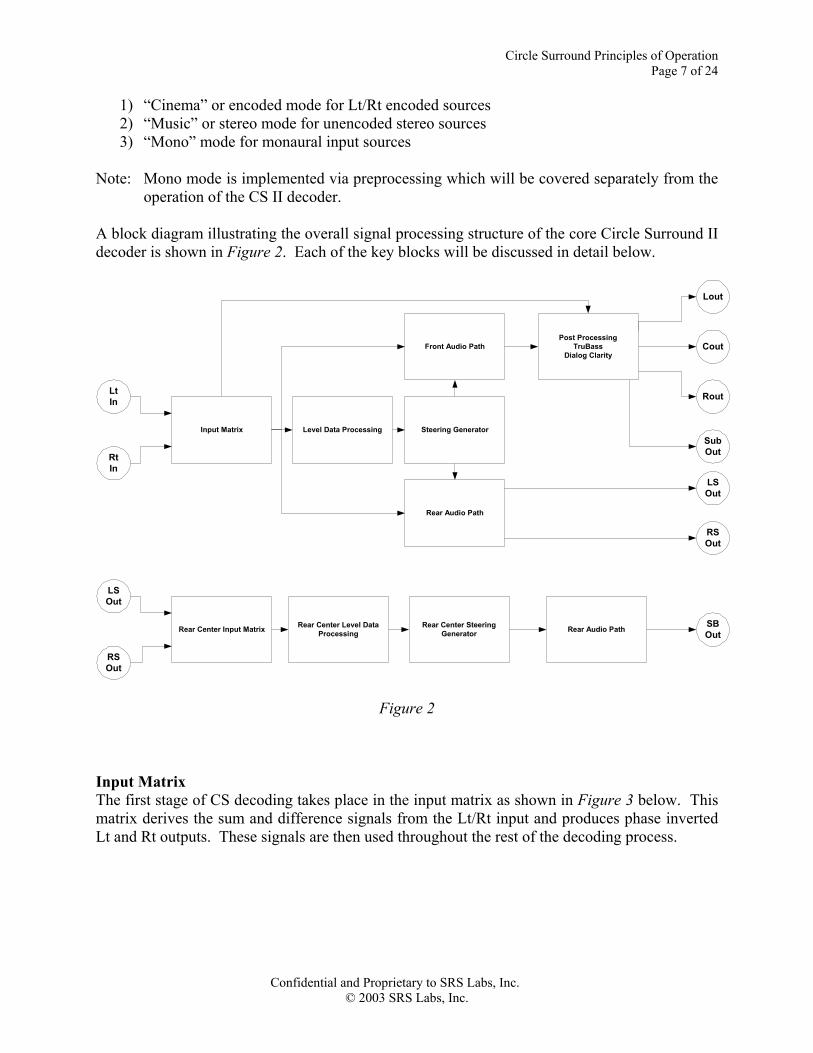
Note: Mono mode is implemented via preprocessing which will be covered separately from the operation of the CS II decoder. A block diagram illustrating the overall signal processing structure of the core Circle Surround II decoder is shown in Figure 2. Each of the key blocks will be discussed in detail below.
Input Matrix Level Data Processing Steering Generator
Front Audio Path
Rear Audio Path
Rear Center Input Matrix Rear Center Level DataProcessing
Rear Center SteeringGenerator Rear Audio Path
Cout
Lout
Rout
LSOut
RSOut
SBOut
LtIn
RtIn
LSOut
RSOut
SubOut
Post ProcessingTruBass
Dialog Clarity
Figure 2
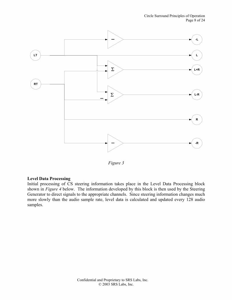
Input Matrix The first stage of CS decoding takes place in the input matrix as shown in Figure 3 below. This matrix derives the sum and difference signals from the Lt/Rt input and produces phase inverted Lt and Rt outputs. These signals are then used throughout the rest of the decoding process.
Circle Surround Principles of Operation Page 8 of 24
Confidential and Proprietary to SRS Labs, Inc. © 2003 SRS Labs, Inc.
LT
RT
L
-R
Σ
Σ_
-L
L+R
L-R
_
R
_
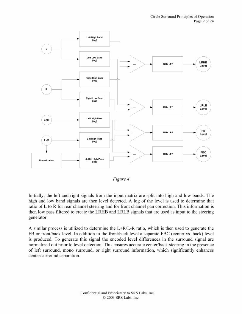
Figure 3 Level Data Processing Initial processing of CS steering information takes place in the Level Data Processing block shown in Figure 4 below. The information developed by this block is then used by the Steering Generator to direct signals to the appropriate channels. Since steering information changes much more slowly than the audio sample rate, level data is calculated and updated every 128 audio samples.
Circle Surround Principles of Operation Page 9 of 24
Confidential and Proprietary to SRS Labs, Inc. © 2003 SRS Labs, Inc.
L
R
L+R
L-R
−
−
Left High Band(log)
Left Low Band(log)
Right HIgh Band(log)
Right Low Band(log)
L+R High Pass(log)
L-R High Pass(log)
32Hz LPF
16Hz LPF
−
Normalization (L-R)n HIgh Pass(log)
−
16Hz LPF
16Hz LPF
LRHBLevel
LRLBLevel
FBLevel
FBCLevel
Figure 4 Initially, the left and right signals from the input matrix are split into high and low bands. The high and low band signals are then level detected. A log of the level is used to determine that ratio of L to R for rear channel steering and for front channel pan correction. This information is then low pass filtered to create the LRHB and LRLB signals that are used as input to the steering generator. A similar process is utilized to determine the L+R/L-R ratio, which is then used to generate the FB or front/back level. In addition to the front/back level a separate FBC (center vs. back) level is produced. To generate this signal the encoded level differences in the surround signal are normalized out prior to level detection. This ensures accurate center/back steering in the presence of left surround, mono surround, or right surround information, which significantly enhances center/surround separation.
Circle Surround Principles of Operation Page 10 of 24
Confidential and Proprietary to SRS Labs, Inc. © 2003 SRS Labs, Inc.
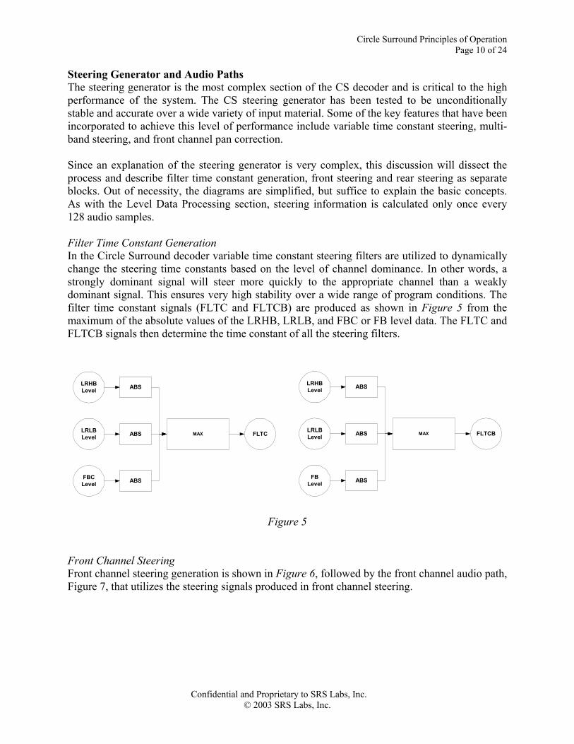
Steering Generator and Audio Paths The steering generator is the most complex section of the CS decoder and is critical to the high performance of the system. The CS steering generator has been tested to be unconditionally stable and accurate over a wide variety of input material. Some of the key features that have been incorporated to achieve this level of performance include variable time constant steering, multi-band steering, and front channel pan correction. Since an explanation of the steering generator is very complex, this discussion will dissect the process and describe filter time constant generation, front steering and rear steering as separate blocks. Out of necessity, the diagrams are simplified, but suffice to explain the basic concepts. As with the Level Data Processing section, steering information is calculated only once every 128 audio samples. Filter Time Constant Generation In the Circle Surround decoder variable time constant steering filters are utilized to dynamically change the steering time constants based on the level of channel dominance. In other words, a strongly dominant signal will steer more quickly to the appropriate channel than a weakly dominant signal. This ensures very high stability over a wide range of program conditions. The filter time constant signals (FLTC and FLTCB) are produced as shown in Figure 5 from the maximum of the absolute values of the LRHB, LRLB, and FBC or FB level data. The FLTC and FLTCB signals then determine the time constant of all the steering filters.
LRHBLevel
LRLBLevel
FBCLevel
MAX
ABS
ABS
ABS FLTC
LRHBLevel
LRLBLevel
FBLevel
MAX
ABS
ABS
ABS FLTCB
Figure 5 Front Channel Steering Front channel steering generation is shown in Figure 6, followed by the front channel audio path, Figure 7, that utilizes the steering signals produced in front channel steering.

Circle Surround Principles of Operation Page 11 of 24
Confidential and Proprietary to SRS Labs, Inc. © 2003 SRS Labs, Inc.
LRLBLevel
FBLevel
FBCLevel
MAX
MAX
−
C1
0
0
LbAdaptive
FLTC
Flv
Frv
RL
FbAdaptive
FLTCB
Exponential Ratio BV
Offset-MAX
FbAdaptiveC
FLTC
0C1 Gain Adj.
RL
Σ CV
MAX
Unencoded Mode
Lt/Rt Mode
Figure 6 The LRLB (Left/Right Low Band) signal produced by the level data processing block is used to produce three front steering signals: Flv, indicating front left dominance, Frv, indicating front right dominance and RL, which indicates right/left dominance as opposed to center dominance. Initially the LRLB level is passed though a variable time constant filter controlled by FLTC, as previously discussed. The “Max” blocks then function to analyze the relationship between the raw center steering signal and the L and R steering signals and also ensure that only positive outputs are produced. The maximum value of the Flv or Frv signals is then used as the RL dominance signal. BV or “Back Voltage” is used to steer surround information away from the front channels and to the surrounds. After adaptive filtering of the FB signal, an exponential curve is applied that makes surround steering more aggressive as the surrounds become increasingly dominant. Lastly, the FBC level produces the CV steering information that is used to steer to the center and away from L and R in presence of correlated information on the Lt/Rt input. Again, after
Circle Surround Principles of Operation Page 12 of 24
Confidential and Proprietary to SRS Labs, Inc. © 2003 SRS Labs, Inc.
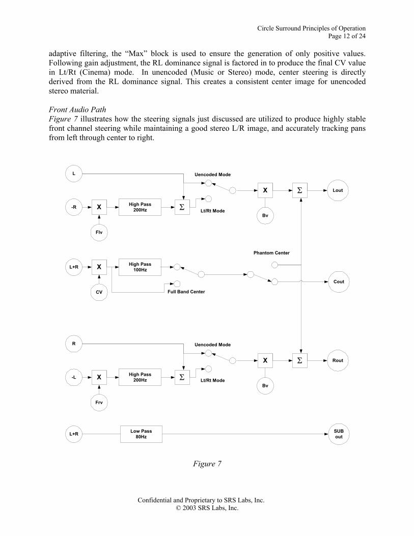
adaptive filtering, the “Max” block is used to ensure the generation of only positive values. Following gain adjustment, the RL dominance signal is factored in to produce the final CV value in Lt/Rt (Cinema) mode. In unencoded (Music or Stereo) mode, center steering is directly derived from the RL dominance signal. This creates a consistent center image for unencoded stereo material. Front Audio Path Figure 7 illustrates how the steering signals just discussed are utilized to produce highly stable front channel steering while maintaining a good stereo L/R image, and accurately tracking pans from left through center to right.
L
-R
Flv
X High Pass200Hz Σ
X
Bv
Lout
Uencoded Mode
Lt/Rt Mode
R
-L
Frv
X High Pass200Hz Σ
X
Bv
Uencoded Mode
Lt/Rt Mode
L+R
CV
X High Pass100Hz
Full Band Center
Σ
RoutΣ
Cout
Phantom Center
L+R Low Pass80Hz
SUBout
Figure 7
Circle Surround Principles of Operation Page 13 of 24
Confidential and Proprietary to SRS Labs, Inc. © 2003 SRS Labs, Inc.
In unencoded mode, the left and right channels are directly fed to the left and right outputs with their level controlled by Bv, which steers away from the front channels in the presence of strong surround dominance. By essentially leaving the left and right channels unmodified except for surround steering, the integrity of the front stereo image is maintained and collapse of the image to the center channel is avoided. In Lt/Rt mode, the Flv and Frv steering signals are used to control the subtraction of opposing channel information above 200hz from front left and right. This effectively cancels center information from the left and right front channels in this mode. Once this processing is complete, the signal is steered by Bv in the same manner as the unencoded mode. The center channel is steered by CV and then processed through a selectable high pass filter to enable user selection of either a band limited or full band center channel. The center channel output is then either routed directly out, or mixed with the left and right front channels if phantom center is selected. Prior to this routing selection in the full CS II implementation the selectable Dialog Clarity post process can be applied. (Post Processing is discussed in section IV.) The subwoofer channel is derived from L+R using a second order 80hz low pass filter. Rear Channel Steering In the Circle Surround decode circuit, rear steering must provide the means to accurately steer to the left and right surrounds based on the encoded information in the Lt/Rt input. This is accomplished via the rear steering logic shown in Figure 8.

Circle Surround Principles of Operation Page 14 of 24
Confidential and Proprietary to SRS Labs, Inc. © 2003 SRS Labs, Inc.
LRHBLevel MAX
MAX
−
0
0
HbAdaptive
FLTC
LsHbVariableMultiplier
RsHb
FbAdaptive
FLTC
LRLBLevel MAX
MAX
−
0
0
LbAdaptive
FLTC
LsLbVariableMultiplier
RsLb
FBCLevel
Figure 8 To minimize erratic steering between the rear channels, the rear steering information is separately processed for the high band and low band. This avoids pan position modulation of high frequency surround information by low frequency information, and vice versa, resulting in smooth and highly stable rear channel steering. In both high and low band processing, rear steering information is derived by monitoring the left/right channel dominance of the out of phase surround signal. As discussed in the encoder section above, left and right surround information is encoded by altering the balance of the encoded surround signal by about 3db. In other words, if the antiphasic surround signal is left dominant by 3db then left surround is indicated, if it is right dominant by 3db then the reverse is true. Smooth panning between the surrounds is ensured by a combination of the encoding method, the decoding method and dual band steering. To accurately decode this slight imbalance in the surround signal, the variable multipliers shown above are designed to exponentially amplify the effect of the imbalance as the surround signal
Circle Surround Principles of Operation Page 15 of 24
Confidential and Proprietary to SRS Labs, Inc. © 2003 SRS Labs, Inc.
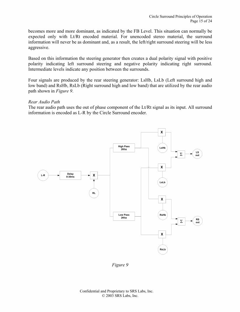
becomes more and more dominant, as indicated by the FB Level. This situation can normally be expected only with Lt/Rt encoded material. For unencoded stereo material, the surround information will never be as dominant and, as a result, the left/right surround steering will be less aggressive. Based on this information the steering generator then creates a dual polarity signal with positive polarity indicating left surround steering and negative polarity indicating right surround. Intermediate levels indicate any position between the surrounds. Four signals are produced by the rear steering generator: LsHb, LsLb (Left surround high and low band) and RsHb, RsLb (Right surround high and low band) that are utilized by the rear audio path shown in Figure 9. Rear Audio Path The rear audio path uses the out of phase component of the Lt/Rt signal as its input. All surround information is encoded as L-R by the Circle Surround encoder.
L-R Delay0-30ms
RL
X
High Pass2Khz
Low Pass2Khz
X
X
LsHb
LsLb
LSoutΣ
X
X
RsHb
RsLb
RSoutΣ
Figure 9
Circle Surround Principles of Operation Page 16 of 24
Confidential and Proprietary to SRS Labs, Inc. © 2003 SRS Labs, Inc.
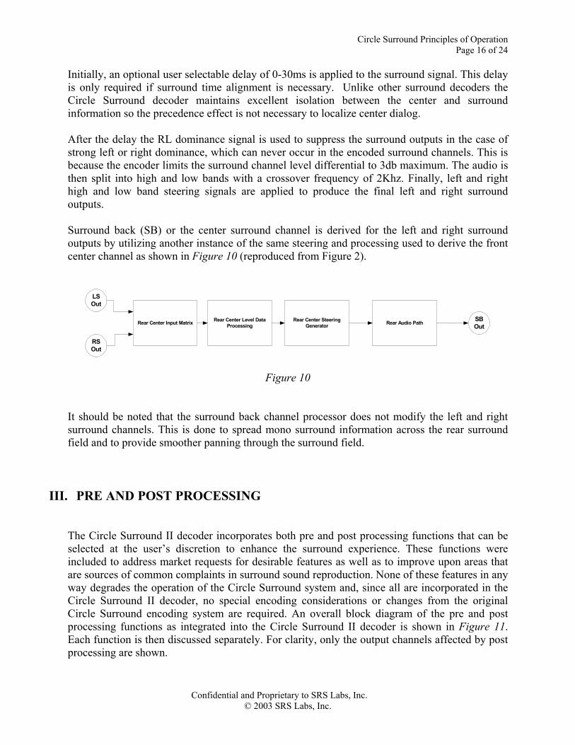
Initially, an optional user selectable delay of 0-30ms is applied to the surround signal. This delay is only required if surround time alignment is necessary. Unlike other surround decoders the Circle Surround decoder maintains excellent isolation between the center and surround information so the precedence effect is not necessary to localize center dialog. After the delay the RL dominance signal is used to suppress the surround outputs in the case of strong left or right dominance, which can never occur in the encoded surround channels. This is because the encoder limits the surround channel level differential to 3db maximum. The audio is then split into high and low bands with a crossover frequency of 2Khz. Finally, left and right high and low band steering signals are applied to produce the final left and right surround outputs. Surround back (SB) or the center surround channel is derived for the left and right surround outputs by utilizing another instance of the same steering and processing used to derive the front center channel as shown in Figure 10 (reproduced from Figure 2).
Rear Center Input Matrix Rear Center Level DataProcessing
Rear Center SteeringGenerator Rear Audio Path SB
Out
LSOut
RSOut
Figure 10
It should be noted that the surround back channel processor does not modify the left and right surround channels. This is done to spread mono surround information across the rear surround field and to provide smoother panning through the surround field.
III. PRE AND POST PROCESSING
The Circle Surround II decoder incorporates both pre and post processing functions that can be selected at the user’s discretion to enhance the surround experience. These functions were included to address market requests for desirable features as well as to improve upon areas that are sources of common complaints in surround sound reproduction. None of these features in any way degrades the operation of the Circle Surround system and, since all are incorporated in the Circle Surround II decoder, no special encoding considerations or changes from the original Circle Surround encoding system are required. An overall block diagram of the pre and post processing functions as integrated into the Circle Surround II decoder is shown in Figure 11. Each function is then discussed separately. For clarity, only the output channels affected by post processing are shown.

Circle Surround Principles of Operation Page 17 of 24
Confidential and Proprietary to SRS Labs, Inc. © 2003 SRS Labs, Inc.
Monaural Input Processor
Ltin
RtIn
ΣCircle Surround
Decoder
Dialog Clarity ProcessorCenter
Cout
TruBass Processor
Σ
Σ
Σ
Left Front
Right Front
LFE
Lout
Rout
Subout
Mono Mode
Trubass Front
Trubass Sub
Dialog Clarity
Figure 11 Monaural Input to Surround Due to the continued prevalence of monaural material and broadcasts throughout the world, it became apparent that the ability to create a creditable surround experience from a single channel input would be desirable. However, conventional techniques such as the use of reverb to simulate ambience in the rear channel were deemed unacceptable as they created very artificial and undesirable side effects. The most obvious of which is a “voice in a tunnel” effect on dialog. It was also recognized that it was highly desirable to retain front/center dialog localization, even though dialog cannot actually be separated from a monaural signal. To address these issues and create a very natural surround experience from a single input, an SRS Labs patented technique was utilized. This technique uses constant phase filters to synthesize a stereo signal that is then applied to the Circle Surround decoder. Unlike conventional techniques that use comb filtering for stereo synthesis, essentially flat frequency response is maintained for both channels under all conditions. In addition, center dialog localization in maintained for a wide range of listening positions. This method of creating 5.1 or 6.1 channels from a monaural signal produces a very immersive surround experience that does not call attention to itself while significantly increasing the enjoyment of monaural material. Dialog Enhancement A universal complaint among users of surround sound systems of any type is that dialog cannot always be clearly understood. This is frequently due to the high level of music, effects, and surround information in modern soundtracks. As exciting as these effects can be, nothing is more annoying than the inability to follow the story due to a lack of clearly understandable dialog. To address this problem, SRS adapted one of its patented techniques which was originally developed to elevate the stereo image vertically in automotive applications. Manufacturers of television receivers quickly adopted this frequency contouring method, which is based on vertical HRTF’s (Head Related Transfer Functions), when it was found that, when used in moderation, dialog clarity was significantly improved.

Circle Surround Principles of Operation Page 18 of 24
Confidential and Proprietary to SRS Labs, Inc. © 2003 SRS Labs, Inc.
Based on this experience a further revised version of this method is applied as a user selectable post process to the center channel output of the Circle Surround II decoder. This process is available in both true center and phantom center modes. The result is significantly improved dialog intelligibility, providing the listener the opportunity to relax and enjoy the film without straining to understand the dialog. Virtual Bass Enhancement Much of the aural excitement in the cinema experience is produced by the impact of low bass from explosions to the ominous tones of the cellos and double basses in a suspenseful scene. Frequently, however, the drivers available in less expensive home surround systems, even with the use of subwoofer, are not capable of fully reproducing the low frequency energy contained in film soundtracks mixed for huge high powered commercial cinema systems. Even larger, more expensive systems can generally benefit from additional low bass impact. To address this and provide the most exciting listening experience possible, SRS Labs’ patented TruBass technology has been integrated in the Circle Surround II decoder. Based on the “missing fundamental” principle, TruBass selectively boosts a series of low bass harmonics within the range that a given driver is capable of reproducing. Since the ear is non-linear at low frequencies, these harmonic series create the perception of very low frequency difference tones below the cutoff frequency of the driver. Various speaker size settings are available to permit the TruBass process to function effectively with a wide range of drivers. Subsequent to the harmonic processing discussed above TruBass incorporates dynamic processing to increase bass impact without creating over excursion in the drivers. Other filters within the TruBass process are designed to carefully avoid “muddiness” or a lack of clarity in any part of the frequency spectrum. As implemented in the Circle Surround II decoder, the TruBass processor derives it’s input from the original Lt/Rt source prior to decoding. TruBass processing is then applied and the output is made available for mixing with either the left and right main signals, the subwoofer signal or both, based on user selection. TruBass, as integrated with Circle Surround II, provides an extremely powerful and cinematic listening experience while retaining the clarity of all the elements in the original mix.
Circle Surround Principles of Operation Page 19 of 24
Confidential and Proprietary to SRS Labs, Inc. © 2003 SRS Labs, Inc.
IV. APPLICATIONS Because Circle Surround does not dictate the characteristics of the transmission or storage medium for 5.1 or 6.1 channel surround sound it opens a wide range of applications for surround that were previously unavailable or impractical. In addition, backward compatibility with other surround decoders and stereo or mono playback further expands the versatility of Circle Surround encoding. Finally, for applications that require synchronization with picture, Circle Surround provides very low encode/decode latency. As an example, latency of the SRS CSE-07 Circle Surround encoder is 8.2ms, while latency of the SRS CSD-07 Circle Surround decoder is 10.2ms. Below are just a few of the key applications for the Circle Surround system:
• Broadcast – Circle Surround provides the capability to transmit 5.1 or 6.1-channel surround audio over the current stereo broadcast distribution and delivery infrastructure. Backward compatibility ensures that all listeners will receive usable audio, while those listeners using a Circle Surround decoder will receive a maximized surround experience. Production of sports and other live events benefit from the characteristics of the Circle Surround matrix, which creates a fully immersive surround experience even when relatively straightforward mixing techniques are used.
• Music production and distribution – With the increased production of 5.1 music
material, Circle Surround can provide a means for distribution of this surround content on standard CDs. Backward compatibility eliminates the requirement for dual inventory.
• DVD recordable and PVR – The Circle Surround encoder, which requires minimal
processing resources, can be incorporated into these devices to preserve 5.1 audio material on two channel PCM or compressed tracks.
• Streaming audio – Circle Surround encoding/decoding delivers an excellent surround
experience when transmitted over compressed audio bitstreams as low as 48Kbps.
• Video-On-Demand (VOD) – Because Circle Surround encoded material can be transmitted very efficiently, VOD systems can preserve 5.1 channels through the transmission process while utilizing a minimum amount of system bandwidth for audio.
• Consumer audio – Because the Circle Surround II decoder is capable of creating
surround sound from virtually any source and allows consumers to experience surround sound from a wider range of material than would otherwise be possible, it provides an added value and benefit to A/V receivers, set-top boxes and Home Theater in a Box systems.
Circle Surround Principles of Operation Page 20 of 24
Confidential and Proprietary to SRS Labs, Inc. © 2003 SRS Labs, Inc.
In conclusion, the highly versatile Circle Surround technology provides a high performance 5.1 or 6.1 multichannel encode/decode system that can be used to significantly expand the range of surround sound storage and transmission options available to the content creation and consumer electronics communities.
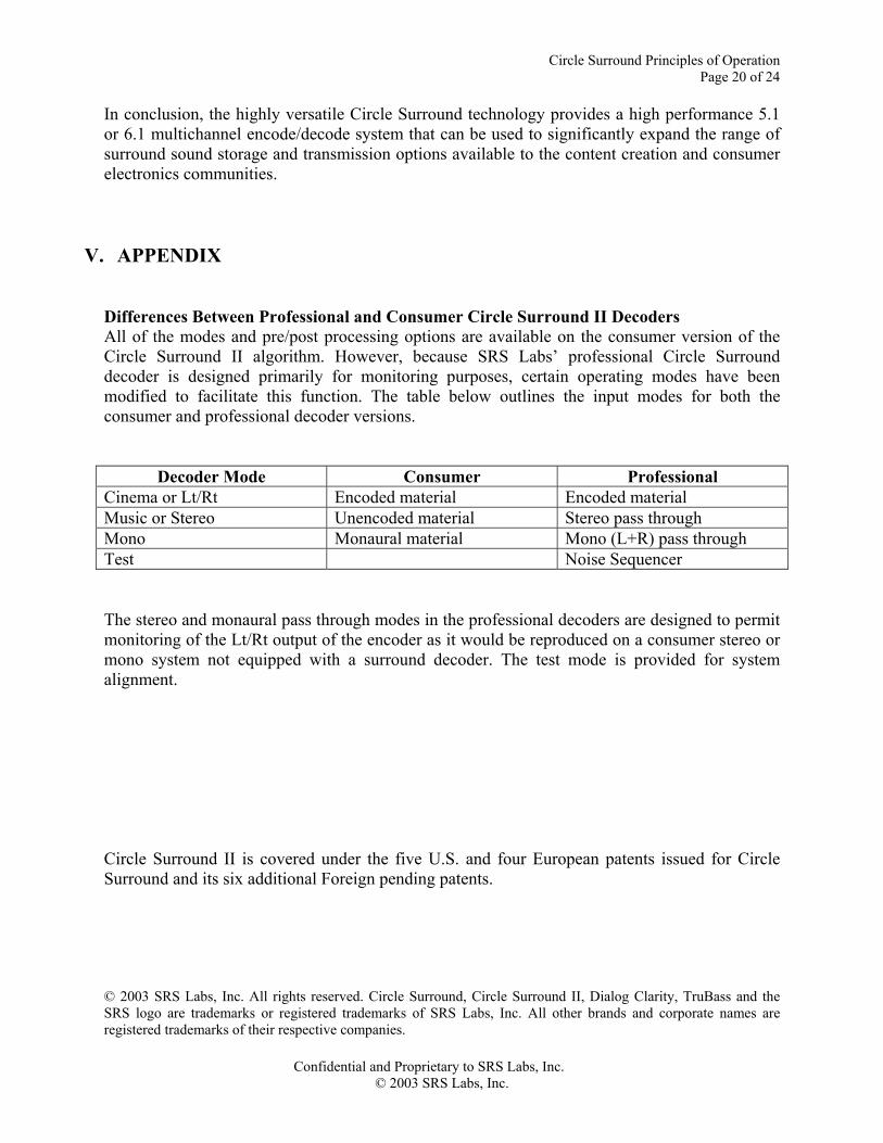
V. APPENDIX Differences Between Professional and Consumer Circle Surround II Decoders All of the modes and pre/post processing options are available on the consumer version of the Circle Surround II algorithm. However, because SRS Labs’ professional Circle Surround decoder is designed primarily for monitoring purposes, certain operating modes have been modified to facilitate this function. The table below outlines the input modes for both the consumer and professional decoder versions.
Decoder Mode Consumer Professional Cinema or Lt/Rt Encoded material Encoded material Music or Stereo Unencoded material Stereo pass through Mono Monaural material Mono (L+R) pass through Test Noise Sequencer The stereo and monaural pass through modes in the professional decoders are designed to permit monitoring of the Lt/Rt output of the encoder as it would be reproduced on a consumer stereo or mono system not equipped with a surround decoder. The test mode is provided for system alignment. Circle Surround II is covered under the five U.S. and four European patents issued for Circle Surround and its six additional Foreign pending patents. © 2003 SRS Labs, Inc. All rights reserved. Circle Surround, Circle Surround II, Dialog Clarity, TruBass and the SRS logo are trademarks or registered trademarks of SRS Labs, Inc. All other brands and corporate names are registered trademarks of their respective companies.

Circle Surround Principles of Operation Page 21 of 24
Confidential and Proprietary to SRS Labs, Inc. © 2003 SRS Labs, Inc.

Circle Surround Principles of Operation Page 22 of 24
Confidential and Proprietary to SRS Labs, Inc. © 2003 SRS Labs, Inc.

Circle Surround Principles of Operation Page 23 of 24
Confidential and Proprietary to SRS Labs, Inc. © 2003 SRS Labs, Inc.

Circle Surround Principles of Operation Page 24 of 24
Confidential and Proprietary to SRS Labs, Inc. © 2003 SRS Labs, Inc.