cicek, k., hu, z., zhu, j., meriggi, l., li, s., nong, z., yu, s. … · zhao, x. li, g. li, and j....
TRANSCRIPT

Cicek, K., Hu, Z., Zhu, J., Meriggi, L., Li, S., Nong, Z., ... Yu, S. (2016).Integrated optical vortex beam receivers. Optics Express, 24(25), 28529-28539. DOI: 10.1364/OE.24.028529
Peer reviewed version
License (if available):CC BY-NC
Link to published version (if available):10.1364/OE.24.028529
Link to publication record in Explore Bristol ResearchPDF-document
This is the author accepted manuscript (AAM). The final published version (version of record) is available onlinevia OSA at https://www.osapublishing.org/oe/abstract.cfm?uri=oe-24-25-28529. Please refer to any applicableterms of use of the publisher.
University of Bristol - Explore Bristol ResearchGeneral rights
This document is made available in accordance with publisher policies. Please cite only the publishedversion using the reference above. Full terms of use are available:http://www.bristol.ac.uk/pure/about/ebr-terms

1
Integrated optical vortex beam receivers
KENAN CICEK,1 ZIYANG HU,1 JIANGBO ZHU,1,* LAURA MERIGGI,2 SHIMAO
LI,3 ZHICHAO NONG,3 SHENGQIAN GAO,3 NING ZHANG,1,2 XUYANG WANG,1
XINLUN CAI,3,4 MARC SOREL,2 AND SIYUAN YU,1,3
1Photonics Group, Merchant Venturers School of Engineering, University of Bristol, Bristol BS8 1UB, UK 2School of Engineering University of Glasgow, Glasgow G12 8LT, UK 3State Key Laboratory of Optoelectronic Materials and Technologies, School of Electronics and Information Technology, Sun Yat-sen University, Guangzhou 510275, China [email protected] *[email protected]
Abstract: A simple and ultra-compact integrated optical vortex beam receiver device is presented. The device is based on the coupling between the optical vortex modes and whispering gallery modes in a micro-ring resonator via embedded angular gratings, which provides the selective reception of optical vortex modes with definitive total angular momentum (summation of spin and orbital angular momentum) through the phase matching condition in the coupling process. Experimental characterization confirms the correct detection of the total angular momentum carried by the vortex beams incident on the device. In addition, photonic spin-controlled unidirectional excitation of whispering-gallery modes in the ring receiver is also observed, and utilized to differentiate between left- and right-circular polarizations and therefore unambiguously identify the orbital angular momentum of incident light. Such characteristics provide an effective mode-selective receiver for the eigen-modes in orbital angular momentum fiber transmission where the circularly polarized OAM modes can be used as data communications channels in multiplexed communications or as photonic states in quantum information applications.
© 2016 Optical Society of America
OCIS Codes: (050.1950) Diffraction gratings; (050.4865) Optical vortices; (130.3120) Integrated optics devices; (130.5440) Polarization-selective devices.
References and Links
1. L. Allen, M. Beijersbergen, R. J. C. Spreeuw, and J. P. Woerdman, "Orbital angular momentum of light and the transformation of Laguerre-Gaussian laser modes," Phys. Rev. A 45, 8185-8189 (1992).
2. J. Wang, J. Y. Yang, I. M. Fazal, N. Ahmed, Y. Yan, H. Huang, Y. Ren, Y. Yue, S. Dolinar, M. Tur, and A. E. Willner, "Terabit free-space data transmission employing orbital angular momentum multiplexing," Nat. Photonics 6, 488-496 (2012).
3. S. Chavez-Cerda, M. J. Padgett, I. Allison, G. H. C. New, J. C. Gutierrez-Vega, A. T. O’Neil, I. MacVicar, and J. Courtial, "Holographic generation and orbital angular momentum of high-order Mathieu beams," J. Opt. B: Quantum S. O. 4, 52-57 (2002).
4. J. Leach, M. J. Padgett, S. M. Barnett, and S. Franke-Arnold, and J. Courtial, "Measuring the orbital angular momentum of a single photon" Phys. Rev. Lett. 88, 257901-1-4 (2002).
5. J. T. Barreiro, T. Wei, and P. G. Kwiat, "Beating the channel capacity limit for linear photonic superdense coding.," Nat. Phys. 4, 282-286 (2008).
6. A. Mair, A. Vaziri, G. Weihs, and A. Zeilinger, "Entanglement of the orbital angular momentum states of photons," Nature 412, 313-316 (2001).
7. G. Gibson, J. Courtial, M. J. Padgett, M. Vasnetsov, V. Pas’ko, S. M. Barnett, and S. Franke-Arnold, "Free-space information transfer using light beams carrying orbital angular momentum," Opt. Express 12, 5448-5456 (2004).
8. J. H. Shapiro, S. Guha, and B. I. Erkmen, "Ultimate channel capacity of free-space optical communications," J. Opt. Netw. 4, 501-516 (2005).
9. D. Richardson, J. Fini, and L. E. Nelson, "Space-division multiplexing in optical fibres," Nat. Photonics 7, 354-362 (2013).
10. T. Ohgane, T. Nishimura, and Y. Ogawa, "Applications of space division multiplexing and those performance in a MIMO channel," IEICE Trans. Commun. E88-B, 1843-1851 (2005).

2
11. S. Koenig, D. Lopez-Diaz, J. Antes, F. Boes, R. Henneberger, A. Leuther, A. Tessmann, R. Schmogrow, D. Hillerkuss, R. Palmer, T. Zwick, C. Koos, W. Freude, O. Ambacher, J. Leuthold and I. Kallfass, "Wireless sub-THz communication system with high data rate," Nat. Photonics 7, 977-981 (2013).
12. F. Tamburini, E. Mari, A. Sponselli, F. Romanato, B. Thidé, A. Bianchini, L. Palmieri, and C. G. Someda, "Encoding many channels on the same frequency through radio vorticity: first experimental test," New J. Phys. 14, 033001 (2012).
13. N. Zhao, X. Li, G. Li, and J. M. Kahn, "Capacity limits of spatially multiplexed free-space communication," Nat. Photonics 9, 822-826 (2015).
14. B. Guan, R. P. Scott, C. Qin, N. K. Fontaine, T. Su, C. Ferrari, M. Cappuzzo, F. Klemens, B. Keller, M. Earnshaw, and S. J. B. Yoo, "Free-space coherent optical communication with orbital angular, momentum multiplexing/demultiplexing using a hybrid 3D photonic integrated circuit," Opt. Express 22, 145-156 (2014).
15. J. Sun, A. Yaacobi, M. Moresco, D. Coolbaugh, and M. R. Watts, "Chip-scale continuously tunable optical orbital angular momentum generator," https://arxiv.org/abs/1408.3315.
16. Y. Yan, G. Xie, M. P. J. Lavery, H. Huang, N. Ahmed, C. Bao, Y. Ren, Y. Cao, L. Li, Z. Zhao, A. F. Molisch, M. Tur, M. J. Padgett, and A. E. Willner, "High-capacity millimetre-wave communications with orbital angular momentum multiplexing," Nat. Commun. 5, 4876 (2014).
17. H. Huang, Y. Ren, G. Xie, Y. Yan, Y. Yue, N. Ahmed, M. P. J. Lavery, M. J. Padgett, S. Dolinar, M. Tur, and A. E. Willner, "Tunable orbital angular momentum mode filter based on optical geometric transformation," Opt. Lett. 39, 1689-1692 (2014).
18. N. K. Fontaine, C. R. Doerr, and L. Buhl, "Efficient multiplexing and demultiplexing of free-space orbital angular momentum using photonic integrated circuits," in Optical Fiber Communication Conference, (Optical Society of America, 2012), paper OTu1I.2.
19. D. Zhang, X. Feng, and Y. Huang, "Encoding and decoding of orbital angular momentum for wireless optical interconnects on chip," Opt. Express. 20, 26986–26995 (2013).
20. X. Cai, J. Wang, M. J. Strain, B. J. Morris, J. Zhu, M. Sorel, J. L. O’Brien, M. G. Thompson, and S. Yu, "Integrated compact optical vortex beam emitters," Science 338, 363-366 (2012).
21. J. Zhu, Y. Chen, Y. Zhang, X. Cai, and S. Yu, "Spin and orbital angular momentum and their conversion in cylindrical vector vortices," Opt. Lett. 39, 4435-4438 (2014).
22. J. Zhu, X. Cai, Y. Chen, and S. Yu, "Theoretical model for angular grating-based integrated optical vortex beam emitters," Opt. Lett. 38, 1343-1345 (2013).
23. A. M. Yao and M. J. Padgett, "Orbital angular momentum: origins, behavior and applications," Adv. Opt. Photonics 3, 161-204 (2011).
24. A. O’Neil, I. MacVicar, L. Allen, and M. J. Padgett, "Intrinsic and extrinsic nature of the orbital angular momentum of a light beam," Phys. Rev. Lett. 88, 053601 (2002).
25. N. Bozinovic, Y. Yue, Y. Ren, M. Tur, P. Kristensen, H. Huang, A. E. Willner, and S. Ramachandran, "Terabit scale orbital angular momentum mode division multiplexing in fibers," Science 340, 1545-1548 (2013).
26. A. E. Willner, H. Huang, Y. Yan, Y. Ren, N. Ahmed, G. Xie, C. Bao, L. Li, Y. Cao, Z. Zhao, J. Wang, M. P. J. Lavery, M. Tur, S. Ramachandran, A. F. Molisch, N. Ashrafi, and S. Ashrafi, "Optical communications using orbital angular momentum beams," Adv. Opt. Photonics 7, 66-106 (2015).
27. H. Huang, G. Milione, M. P. J. Lavery, G. Xie, Y. Ren, Y. Cao, N. Ahmed, T. An Nguyen, D. A. Nolan, M.-J. Li, M. Tur, R. R. Alfano, and A. E. Willner, "Mode division multiplexing using an orbital angular momentum mode sorter and MIMO-DSP over a graded-index few-mode optical fibre," Sci. Rep. 5, 14931 (2015).
28. L. Wang, P. Vaity, S. Chatigny, Y. Messaddeq, L. A. Rusch, and S. LaRochelle, "Orbital-angular-momentum polarization mode dispersion in optical fibers," J. Lightwave Technol. 34, 1661-1671 (2016).
29. P. Vaity and L. Rusch, "Perfect vortex beam: Fourier transformation of a Bessel beam," Opt. Lett. 40, 597-600 (2015).
30. R. Zambrini and S. M. Barnett, "Quasi-intrinsic angular momentum and the measurement of its spectrum," Phys. Rev. Lett. 96, 113901 (2006).
31. J. Petersen, J. Volz, and A. Rauschenbeutel, "Chiral nanophotonic waveguide interface based on spin-orbit interaction of light," Science 346, 67-71 (2014).
32. K. Y. Bliokh and F. Nori, "Transverse and longitudinal angular momenta of light," Phys. Rep. 592, 1-38 (2015). 33. N. Zhang, K. Cicek, J. Zhu, S. Li, H. Li, M. Sorel, X. Cai, and S. Yu, "Manipulating optical vortices using
integrated photonics," Front. Optoelectron. 9, 194-205 (2016). 34. M. J. Strain, X. Cai, J. Wang, J. Zhu, D. B. Phillips, L. Chen, M. Lopez-Garcia, J. L. O’Brien, M. G.
Thompson, M. Sorel, and S. Yu, "Fast electrical switching of orbital angular momentum modes using ultra-compact integrated vortex emitters," Nat. Commun. 5, 4856 (2014).
35. S. A. Schulz, T. Machula, E. Karimi, and R. W. Boyd, "Integrated multi vector vortex beam generator," Opt. Express 21, 16130-16141 (2013).
1. Introduction
Since the work of Allen et al. [1] on the existence of optical orbital angular momentum (OAM) in the light beams with spiral wave fronts, numerous schemes have been demonstrated not only theoretically but also experimentally in the generation, manipulation

3
and detection of OAM beams [2-4]. The possibility of providing a much larger state space suggests the OAM of light could be tapped for potentials in increasing data transmission capacity and in classical or further improving security in quantum information systems [5-8]. For the classical applications, OAM states can be used directly as a coding alphabet or as a multiplexing/de-multiplexing space. Encoding, transfer or decoding of information using OAM alphabet has been proposed in 2001 by Mair et al [6] and first demonstrated for communication links by Gibson et al in 2004 [7]. While space-division multiplexing (SDM) has been proposed to increases data capacity by means of providing additional multiplexing dimension [9, 10], the orthogonality of OAM beams allows more data to be transmitted in free-space coaxially multiplexed beams at the same frequency [11-13]. The introduction of silicon photonic integrated circuits (PICs) technology has made OAM emitters much more compact and efficient [14, 15]. However, the detection and de-multiplexing of the beams remain a more difficult task. In last decade, the de-multiplexing and detecting of OAM beams has been done by mostly utilizing beam splitters [16] and mode sorters [17]. These techniques require the incoming beam’s mode information in order to detect desired topological charge in the beam. This means that the receiver concept only works for predefined modes. This limitation can be overcome with PIC technology. Last couple of years a few PIC designs have been proposed for OAM beam decoding/de-multiplexing using concentric circular gratings to couple light into radially diverging waveguides [18, 19]. This method enables effective detection for lower OAM topological charge of less than half the number of the waveguides. For higher topological charge detection, more receiving points are needed around the azimuthal direction by the laws of sampling theory. We extend our previous work on micro-ring resonator based OAM emitter device [20] that uses angular-gratings as coupling mechanism between the resonator’s whispering gallery modes (WGMs) and free-space cylindrical vector vortices (CVVs) carrying photonic OAM [21]. We experimentally confirm the rules by which the same coupling mechanism can be used for reception of OAM states, i.e., to detect the total angular momentum (TAM) of an incoming beam and to efficiently collect its energy. Moreover, since this device is operating in the complete (spin and orbital) angular momentum space [21], it can be deployed as the OAM decoding/de-multiplexing component in OAM fiber transmission systems, or free space transmission links seeded by integrated optical vortex emitters of the similar geometry [18-20], without the need of manipulation in polarization states of light. In addition, this receiver spares the need for careful calibration on the phase-sensitive waveguides required for the arrayed waveguide and star-coupler based receivers [14, 18], and offers a simpler configuration and more robust mode selectivity of OAM beams.
2. Theoretical framework
The integrated vortex beam receiver presented in this work is comprised of a micro-ring resonator, an access waveguide and second order gratings engraved on the sidewall of resonator as shown in Fig. (a). When working as the optical vortex emitter by coupling light into the Port A/B as shown in Fig. 1(b), the grating elements perturb the travelling WGMs in the resonator and the diffracted first-order light collectively forms the vertically propagating beams carrying OAM [20]. It should be noted that the emitted beams from this device have cylindrically symmetric polarization distribution in space due to the cylindrical geometry and local vectorial nature of the device, and hence are referred to as cylindrical vector vortices (CVVs) [21, 22]. When used as an optical vortex receiver as shown in Fig. 1(a), this device couples the power in the incident light beam into ring resonator with the gratings, and resonant WGM is formed if the overall geometric phase-matching and local polarization-matching condition is fulfilled. The received power can be detected from one of the two ports of the access waveguide, determined by the wavelength and sign of TAM carried by the incoming beam.

4
To be more specific, the CVV of topological charge TCl emitted from such a device can be
generally decomposed into two circularly polarized scalar vortices, namely, left-hand circularly polarized (LCP) vortex with OAM order of 1TCl − and right-hand circularly
polarized (RCP) vortex of order 1TCl + [20]. It is easy to find that each scalar vortex carries
the TAM of TCl per photon by adding up the two angular momentum components [1], where
is the reduced Planck constant. And thus the whole CVV conserves the TAM of TCl per
photon despite its spatially varying state of polarization (SoP) [21]. Therefore, this device can be used to efficiently receive not only CVV beams, but also their comprising scalar vortices (i.e., circularly polarized OAM beams), making this device a TAM receiver working in the full optical angular momentum domain.
Fig. 1. (a) Schematic of the angular-grating based integrated optical vortex beam receiver, and the spiral phase front shown as the incident optical vortex carrying OAM. (b) Schematic of this receiver operating in the emitter mode.
Mathematically, the topological charge of the output CVV, if the device works as an emitter by externally coupling light into Port A or B shown in Fig. 1(b), can be written as [20]
( )TCl p sign p q= − ∗ (1)
where the integer 2 effp Rnπ λ= is the azimuthal mode number of resonant WGM and q is
the number of grating elements. R is the radius of the ring resonator, effn is the effective index
of WGM, and λ is the wavelength. It is worth to mention that the topological charge TCl is
defined by the near-field spatial phase from the interaction between gratings and WGMs, and also an indication of the TAM density in CVVs [21]. The sign of p (±) in Eq. (1) can be arbitrarily defined by the travelling direction of WGM in the resonator (clockwise or counter-clockwise). Being consistent with the convention of OAM handedness [23], here we assume the mode number p of counter-clockwise (CCW) travelling WGM is positive. Consequently, CCW travelling WGMs coupled from Port A contributes to the emission of CVVs with positive (negative) TCl if the wavelength is shorter (longer) than the center wavelength cλ ,
with which p q= is satisfied. On the contrary, CVVs from Port B has positive (negative)
TCl if the working wavelength is longer (shorter) than cλ . Fig. 2 shows the emission spectrum
and the topological charges at each order of output CVV from one of the devices of R = 14.5

5
μm, with light fed into Port A and exciting CCW modes. The spectrum from Port B injection is almost identical to this one but only with swapped signs of topological charges as shown in the figure.
Given the knowledge above, this device can be generally used to receive the entire family of CVV beams, which exhibit cylindrical symmetric SoP distribution and carry OAM simultaneously, especially including those from the integrated emitters of the similar cylindrical symmetry as this one [15, 18, 20]. For incident CVV of topological charge TCl , the
first-order diffracted light by the gratings accumulates a round-trip phase along the ring and evolves into a travelling WGM if the round-trip phase is an integer multiple of 2π. When detecting at Port A, for example, for each specific incident TAM, there is only one specific wavelength at which this geometric phase-matching condition along the ring is fully satisfied. With the same coupled-mode analysis used in [20], it is straightforward to find that the dominant CW resonance allowed from the first-order diffraction is of the order:
CW TCp l q= − (2)
at the wavelength 2A eff CWRn pλ π= − (note that CWp is negative). Similarly, when detecting
at Port B, the azimuthal mode number of the dominant CCW WGM is
CCW TCp l q= + (3)
at the wavelength 2B eff CCWRn pλ π= . Because of the emitting-receiving reciprocity in this
device, given the wavelength of dominance response at the output ports ( Al or Bl ), the
corresponding detected topological charge, Al or Bl , can be directly read out from the
emission spectrum (e.g., Fig. 2). It is worth mentioning that incident beams at the same resonance wavelength but with opposite signs of topological charges, or TAM, can be coupled and directed separately to the two individual ports. This interesting transformation between the sign of TAM and the propagation direction of beams is a manifestation of the mechanical effect of the longitudinal angular momentum in light [24], and can directly find application in de-multiplexing two OAM beams of opposite TAM with a single receiving unit.
Fig. 2. A typical emission spectral response from a R = 14.5 μm device. The topological charges of the emitted vortices are marked red/blue if CW/CCW WGMs are excited with light injected from the Port B/A. The characteristic split peaks in the center indicating the 0TCl = output [20].

6
In addition to receiving CVV beams, this device can also be used to receive circular-polarized scalar OAM beams. For incident beam with polarization helicity of iσ and OAM order of il ,
the TAM charge ( i ij lσ= + ) can be detected with the dominant resonance at the same
wavelength, Al or Bl , as if CVV of topological charge TC i il lσ= + is being received. With the
read-out charge Al or Bl from emission spectrum, the OAM order carried by this incident
beam can be identified as
,i A B il l σ= − (4)
with the spin angular momentum (SAM) state of circular polarization being 1iσ = ± . It should
be mentioned that the OAM eigen-modes in circular waveguides is generally circular-polarized, including those in OAM fibers being intensively investigated for high-dimensional spatial-mode multiplexing (SDM) communications [25-27]. Therefore, this device is an ideal receiver for these OAM-fiber modes, and no extra manipulation of SoP is needed before receiving. For example, the two degenerate modes of OAM-2L and OAM+2R are both comprised of even and odd HE31 modes in fiber [28], and they can be de-multiplexed to the two individual ports A and B since they carry TAM of opposite signs.
This device should also respond to linearly polarized OAM beams, but with some extent of difficulty in interpreting the received charges. Because of its cylindrical symmetry and local anisotropy at the grating elements [20], optical vortices with rotational symmetry in the full angular momentum space can be unambiguously received for their TAM, including CVVs and circularly polarized OAM beams. However, a linearly polarized vortex of charge il can
be regarded as the combination of two circular-polarized vortices with opposite helicities, namely, with different TAM 1il + and 1il − , and they cannot be detected by the device at the
same wavelength. In fact, this character is shared by all the integrated OAM components of the similar geometry [15, 18, 20]. These devices are all more compatible with CVVs or eigen-modes in circular waveguides.
3. Results and discussion
3.1 Numerical calculations
To validate the theory above, numerical calculations using finite-difference time-domain (FDTD) method (Meep and Lumerical) are first performed. The receiver considered in the calculation is a silicon device of ring radius R = 3.9 μm, based on the silicon-on-insulator (SOI) wafer. The access waveguide and the ring waveguide are both of 500 nm width and 220 nm height. The construction of the receiver also includes angular-gratings with q = 36, engraved on the ring resonator and each element with the dimensions of 60 nm width, 220 nm height and 60 nm length. The small radius of 3.9 μm is chosen because of the reasonable calculation time consumed using the FDTD method. The incident optical vortices used here and in the following experiments are circular-polarized OAM beams. The normal incident beams are set to be concentrically illuminating onto the receiver resonator in order to deliver the accurate phase information. The intensity patterns are scaled in accordance with the near-field emission patterns from the device to realize maximal receiving efficiency. In the calculations below, results are obtained by detecting from Port A.
To verify the capability of the device to detect the individual TAM and OAM charges, in each calculation loop we keep the incident SoP iσ and OAM charge il constant and TAM charge
TC i il lσ= + being one of seven predetermined integers (-3 to +3), and sweep the incident
wavelength in a range covering this seven charges. At the same time, the received power is

7
recorded at Port A. After each loop, an OAM receiver spectral response for one of the incident TAM charges is obtained, shown as a row of bars in Fig. 3.
Fig. 3. Normalized intensity of received TAM charge from Port A (Al ) in case of (a) LCP and (b) RCP incident
beams carrying seven different OAM charges il .
After repeating for all the seven charges and the two SoPs ( 1iσ = ± ), the whole receiving-
matrix is created and shown in Fig. 3. Here the data at each row is normalized to the highest intensity value within the row. As it can be seen that, regardless of incident SoP, both set of plots exhibit only one response distinctively higher than others within each row. This dominant wavelength can be interpreted as the ‘detected’ TAM charge Al by looking up the
corresponding emission spectral response, and the side-mode suppression ratio (SMSR) –defined as the difference in response in the same row – for all the received TAM charges is generally above 10 dB. SMSR can be regarded as the measure of OAM mode selectivity of the device, and a higher SMSR offered by receiver promises a lower crosstalk to be introduced among multiplexed modes after detection. Some side-modes in the matrices with detected charges A TCl l= − , which would have been distinctively detected at Port B, have
slightly higher response than the others, due to the reflection inside the resonator caused by the second-order angular grating. Nevertheless, for all incident beams, it can be seen that TAM carried by the beam is correctly received as A TCl l= , making each matrix in Fig. 3 a
unitary fashion. Furthermore, it can be found that the OAM charges il deduced from the
received Al with Eq. (4) agree with the ones carried by the incident beams, and hence the two
matrices are shifted by the amount of iσ with respect to the identity matrix.
3.2 Measured results and discussions
In order to verify the outcomes of theoretical study, two devices of radii 14.5 µm and 29 µm are fabricated and measured, with other device parameters kept the same as presented in the numerical calculations. A micrograph of the R = 14.5 μm device is shown in Fig. 4(a), as well as in Fig. 4(b) its measured emission spectral response labeled with the CVV topological charges when injecting light into Port A. We choose to measure this device first because of its relatively short center wavelength (around 1535 nm), enabling us to reach higher order
vortices (up to 4TCl = ) with the limited operation wavelength range of our measurement
system.
The experimental setup used to perform the proof-of-principle reception measurement is shown in Fig. 4(c). To start with, the operation wavelength of the tunable laser is set to be on

one of the reLight beam frphase-only sp
‘perfect’ OAM
OAM beam, aincident on thfrom the contand the radiadevice under t
Fig. 4. (a) Microseach resonant wabeam splitter, QWlaser, PD: photo doped fiber ampl
the perfect vortexemitter with light
In order to obused to directpolarized reflquarter-wave
beam is focu
esonance moderom the collimpatial light mo
M beam [29]. T
and inset (ii) ilhe device planetrollable OAMal phase gradietest (DUT) inv
scopic picture of tavelength. (c) ExpWP: quarter wave pdetector, CM: infrlifier. Insets: (i) ph
x beam incident ont seeded from the P
bserve the outpt the beam ontlected beam froplate (QWP) a
used onto the
e of the ring rmator seeded by
dulator (SLM)
The inset (i) in
llustrates the be. Characterizin
M beam size/wient on SLM, tvariant with il
the device with R =perimental setup fplate, LP: linear prared camera, SMFhase pattern for th
n the DUT; (iii) nePort A.
put of SLM to to an infrared om the SLM iand converted t
DUT concen
8
resonator by loy the amplified), which has a
Fig. 4(c) show
beam profile ofng this receiveidth by fine-tuto realize a m[29].
= 14.5 μm. (b) Emfor receiver characolarizer, OL: obje
F: single-mode fibehe generation of pe
ear-field intensity
optimized the camera (CM).
is passed throuto being circula
ntrically with
ooking up the d tunable lasera phase pattern
ws the pattern f
f the generateder with the prefuning the initiamaximized coup
mission spectrum acterization. SLM:
ective lens, DUT: der, PC: polarizatioerfect vortex of
il
distribution of the
beam quality,. After the beaugh a set of linarly polarized
a 20x/0.5 obj
spectrum in Fr output is sentn to generate il
for generating
d perfect annulfect vortices caal Gaussian beapling with the
and the topologica spatial light moddevice under test, on controller, EDF
3= + ; (ii) intensit
e DUT when it op
a beam splitteam splitter, thenear polarizer ( 1iσ = ± ). The
jective lens (O
Fig. 4(b). t onto the
i charged
a 3il = +
lar vortex an benefit am width e receiver
al charges at dulator, BS: TL: tunable
FA: Erbium-ty profile of
perates as an
er (BS) is e linearly (LP) and
e incident
OL), and

9
overlapped with the near-field mode of the DUT, e.g., the one shown as the inset (iii) in Fig. 4(c). The alignment of incidence is monitored with the CM to guarantee good mode overlap and minimize misalignment. The received power is measured from Port A with a photo detector (PD). Then the receiving spectral response of the device, similar to the rows of bars in Fig. 3, can be obtained by sweeping the incident wavelength in the range covering targeted TAM charges.
Receiving with the R = 14.5 μm device, three topological charges ( 2, 3, 4TCl = + + + ) are
targeted. For each TCl , RCP ( 1iσ = − ) OAM beams with orders 1i TCl l= + are generated and
illuminated onto the device. By sweeping the wavelength from tunable laser while keeping the incident power constant, the normalized received spectra from Port A for all three charges are obtained as shown in Fig. 5. The highest received power peak in each plot is regarded as the indication of detected charge Al , and it is confirmed that all the detected charges follow
the rule of A TCl l= as predicted by theory. The SMSRs presented with the three charges, all
around 5 dB, are lower than the simulations. This is primarily caused by the mode mismatch between the incident beams and near-field mode of the device, e.g., as it can be seen from the difference of beam profiles shown as the insets (ii) and (iii) in Fig. 4(c). This mismatch impairs the mode-selection rules given in Eq. (2) and (3) by inducing an incorrect phase response at the grating elements and accumulated phase along the ring, and thus expanding the number of excited WGM orders in the resonator. Although with the ‘perfect’ vortex generation, fine tunability of incident beam size/width is achieved independent of OAM order, modal mismatch is still inevitable given the sub-micron scale receiving area (i.e., the grating elements) of the device. The limited receiving area imposes more critical restrictions on the alignment of incidence, including lateral offset and incident angle, for the grating elements to sample the correct field information. In other words, the SMSR decreases with misalignment due to the quasi-intrinsic nature of optical OAM carried in vortex beams, as misalignment of beam axis from the reference axis introduces OAM side-modes [30]. Optimized designs of the receiver will be studied to ease the requirement on the incident beam for mode-matching, including new design on the grating structure and increasing the effective receiving area.
Fig. 5. Received spectra of three RCP vortices of different charges when detecting from the Port A: (a) 3il = + , (b)
4il = + , (c) 5il = + .
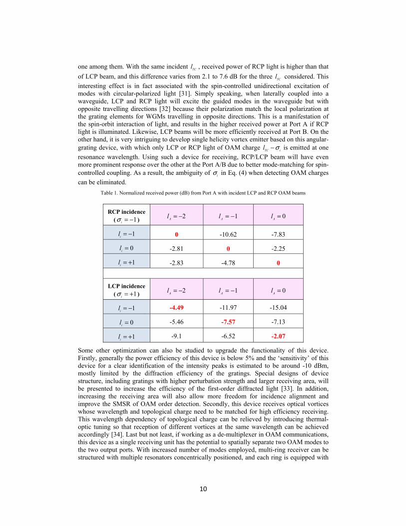
Another surprising phenomenon observed in simulations and measurements is, when detecting at the Port A, the received power of RCP light is always higher than the LCP beam of the same TCl . This observation can be also supported by the results obtained from the other
device of R = 29 μm, with which beams of both circular polarizations are received. The received power at Port A for beams with different orders is listed in Table 1. Note that all the power values with the same received charge Al (each column) are normalized to the highest
10
one among them. With the same incident TCl , received power of RCP light is higher than that
of LCP beam, and this difference varies from 2.1 to 7.6 dB for the three TCl considered. This
interesting effect is in fact associated with the spin-controlled unidirectional excitation of modes with circular-polarized light [31]. Simply speaking, when laterally coupled into a waveguide, LCP and RCP light will excite the guided modes in the waveguide but with opposite travelling directions [32] because their polarization match the local polarization at the grating elements for WGMs travelling in opposite directions. This is a manifestation of the spin-orbit interaction of light, and results in the higher received power at Port A if RCP light is illuminated. Likewise, LCP beams will be more efficiently received at Port B. On the other hand, it is very intriguing to develop single helicity vortex emitter based on this angular-grating device, with which only LCP or RCP light of OAM charge TC il σ− is emitted at one
resonance wavelength. Using such a device for receiving, RCP/LCP beam will have even more prominent response over the other at the Port A/B due to better mode-matching for spin-controlled coupling. As a result, the ambiguity of iσ in Eq. (4) when detecting OAM charges
can be eliminated.
Table 1. Normalized received power (dB) from Port A with incident LCP and RCP OAM beams
RCP incidence ( 1iσ = − ) 2Al = − 1Al = − 0Al =
1il = − 0 -10.62 -7.83
0il = -2.81 0 -2.25
1il = + -2.83 -4.78 0
LCP incidence ( 1iσ = + ) 2Al = − 1Al = − 0Al =
1il = − -4.49 -11.97 -15.04
0il = -5.46 -7.57 -7.13
1il = + -9.1 -6.52 -2.07
Some other optimization can also be studied to upgrade the functionality of this device. Firstly, generally the power efficiency of this device is below 5% and the ‘sensitivity’ of this device for a clear identification of the intensity peaks is estimated to be around -10 dBm, mostly limited by the diffraction efficiency of the gratings. Special designs of device structure, including gratings with higher perturbation strength and larger receiving area, will be presented to increase the efficiency of the first-order diffracted light [33]. In addition, increasing the receiving area will also allow more freedom for incidence alignment and improve the SMSR of OAM order detection. Secondly, this device receives optical vortices whose wavelength and topological charge need to be matched for high efficiency receiving. This wavelength dependency of topological charge can be relieved by introducing thermal-optic tuning so that reception of different vortices at the same wavelength can be achieved accordingly [34]. Last but not least, if working as a de-multiplexer in OAM communications, this device as a single receiving unit has the potential to spatially separate two OAM modes to the two output ports. With increased number of modes employed, multi-ring receiver can be structured with multiple resonators concentrically positioned, and each ring is equipped with

11
an individual access waveguide and two terminal ports [35]. Each ring can be thermally configured [34], and the multiple rings can be synchronized to resonate at a same wavelength but with different TCl . Such a compact receiver can thus be used to de-multiplex 2×n OAM
modes of the same wavelength, where n is the number of the ring units.
4. Conclusion
In this paper, we proposed a novel PIC optical vortex de-multiplexing\decoding component which utilizes a simple ring resonator and second-order angular-gratings. It has been confirmed with measurements that this device can be used to unambiguously detect the total angular momentum of cylindrical vector vortices and circular-polarized vortices, including those OAM modes supported by recently highly interested OAM fibers. It is also found that this device has the capability to discriminate between the two circular polarizations at a single output port, and the detection of OAM states can be thus achieved. The SMSR achieved in measurements is generally around 5 dB with this preliminary design of receiver. Optimization suggestions are outlined to further improve the performance and upgrade the functionality.
Funding
European Union Horizon2020 (project ROAM).
Acknowledgements
Author Kenan Cicek acknowledges the financial support from Ministry of National Education of Turkey.