choosing the right cooling methodology for openvpx deployments
TRANSCRIPT
ABOUT ATRENNE INTEGRATED SOLUTIONSAtrenne Integrated Solutions® is a vertically-integrated, component and system provider serving aerospace, defense, computing, communications, and other technology-driven industries. Atrenne delivers integrated components, electronic packaging, fabricated metal, electronic assemblies and value-add build-to-print manufacturing services to industrial markets across the globe. With more than 40 years of experience, Atrenne provides innovatively engineered products and services throughout the program lifecycle, from concept to manufacturing to obsolescence management. Atrenne is proud to provide customers with fully-tested, reliable, electromechanical solutions on-time and with world-class quality.
Atrenne Integrated Solutions | 10 Mupac Drive | Brockton, MA 02301 | 508-588-6110 | www.atrenne.com
CHOOSING THE RIGHT COOLING METHODOLOGY
Atrenne Integrated Solutions | 10 Mupac Drive | Brockton, MA 02301 | 508-588-6110 | www.atrenne.com
FOR OPENVPX DEPLOYMENTS

Atrenne Integrated Solutions | 10 Mupac Drive | Brockton, MA 02301 | 508-588-6110 | www.atrenne.com
AtrenneIntegrated Solutions
Atrenne Integrated Solutions | 10 Mupac Drive | Brockton, MA 02301 | 508-588-6110 | www.atrenne.com
CHOOSING THE RIGHT COOLING METHODOLOGY FOR OPENVPX DEPLOYMENTS
INTRODUCTIONOpenVPX computing for rugged environments deploys the technology industry’s most advanced silicon solutions into the most extreme environmental conditions. As silicon geometries continue to follow Moore’s law, heat density is increasing significantly. Thermal management in the defense and aerospace rugged systems market has become more and more challenging over time.
THERMAL MANAGEMENT CRITERIAOpenVPX systems can be configured with a wide variety of advanced processing elements, driving huge performance leaps relative to VME and early VPX systems of just a few years ago. Table 1 below shows the significant increase in board power consumption over time. The increased performance levels that processors have been able to achieve bring a design challenge – managing the equally huge leap in power use manifested as heat. Thermal management is a key chassis criterion for these systems and, to avoid issues, some design and architectural parameters must be defined early in a project life cycle.
YEAR BOARD DESCRIPTION POWER CONSUMPTION (W)
PLATFORM STANDARD
2000 Quad PowerPC 7410 40 VME
2005 Quad PowerPC 7448 80 VME
2010 Quad PowerPC 8641 100 VPX
2015 Dual Intel Core-i7 130 OpenVPX
Table 1: Board power consumption over time
ENVIRONMENT VERSUS ARCHITECTUREIdentifying the appropriate thermal solution for a particular application requires communication and interaction with the person who is knowledgeable about the target environment. Ideally, this communication occurs early in the system definition process. The right time to start is prior to the PDR (preliminary design review) meeting and during the system requirements review. The first step in the process is to define the system’s required functions or capabilities. The next step is to determine the system’s (and platform’s) physical constraints. The required functionality and target environment together drive an architectural approach which delivers the performance required, within the cost and SWAP (size, weight and power) budget, for
deployment in the target environment. In practice, this may be an iterative process. For example, a decision might be made as to which module form factor size will suffice, for example 3U (100x160mm) or 6U (233x160mm). This decision is usually driven by space constraints, but there are implications in terms of performance, budget, functionality, channel density, weight and thermal management. Having a good understanding of the most common cooling methodologies available is quite helpful during the phase when architectural trade-offs are being considered.
FOR OPENVPX DEPLOYMENTS
CHOOSING THE RIGHTCOOLING METHODOLOGY
Figure 1: Thermal Analysis reveals hot spots which may then be addressed using thermal management techniques
COOLING METHODOLOGIES FOR MODULESThe mechanical design implementations for OpenVPX are defined in “ANSI/VITA 48.0, Mechanical Specification for Microcomputers using Ruggedized Enhanced Design Implementation (REDI).” VITA 48 defines the most widely used module cooling methodologies:

Atrenne Integrated Solutions | 10 Mupac Drive | Brockton, MA 02301 | 508-588-6110 | www.atrenne.com
the configuration is accurately modeled and validated in simulation. The section below explores the most common chassis cooling configurations
NATURAL CONVECTION: 50W - 300WNatural convection cooling (or passive cooling) is often used for small slot count systems with relatively low power dissipation. This could include small form factor boards, power efficient processors or I/O boards. Natural convection chassis often embed fins on the external chassis walls to maximize surface area contact of the heat conducting chassis exterior with cooling air. Natural convection cooling enables system designers to implement and deploy a system without the need for fans, coldplates, vehicle supplied air, liquid or other supplied resources. This usually makes for a low-cost, high-MTBF (mean time between failures) design.
Atrenne offers several small slot count chassis solutions for natural convection applications. For example, the SFF-BPA974 2-slot Natural Convection chassis is able to operate and survive external air temperatures of 40°C to 60°C using only natural convection for modules dissipating up to 100 Watts.
AtrenneIntegrated Solutions
Air-cooled modules use an aluminum or copper heat sink which is generally lighter than the specially designed heat frames needed for conduction cooling, or liquid flow through. On the other hand, a heat frame provides structural reinforcement of the module which allows it to withstand greater shock and vibration. The most rugged applications tend to use conduction cooled modules and increasingly Liquid Flow Through. Air-cooled modules can still be deployed in certain rugged applications using a transit case or ATR isolation tray.
The amount of module power able to be cooled by the various cooling methodologies ranges from approximately 50W to 700W depending on the technology being used. It is important to get an accurate assessment of module power dissipation. Many system designers use the maximum theoretical power dissipation provided by their module vendor (or designer). These numbers are generally derived through paper analysis or by executing power viruses (applications that cause a machine to dissipate the maximum amount of power possible without regard for performing any useful work). For example, simultaneously executing numerically intensive algorithms, exercising memory controllers, firing DMA controllers, streaming IO, … Generally speaking, real-world applications use less than the maximum theoetical power consumption of a device or board.
The module cooling methodology works hand-in-hand with thermal management designed at the chassis level. The modules and the chassis may use different technologies that work together. For example, a chassis can use a liquid-to-air heat exchanger and support air cooled modules. As another example, a chassis may use liquid cooling or forced air convection to cool the sidewall needed for its conduction cooled modules. In some cases air and conduction cooled modules are mixed within the same chassis. While less common, these designs can be accommodated as long as
FOR OPENVPX DEPLOYMENTS
CHOOSING THE RIGHTCOOLING METHODOLOGY
ANSI/VITA STANDARD SUMMARY DESCRIPTION
48.0 Base Standard
48.1 Air CoolingCooling air flowing directly over
components
48.2 Conduction CoolingModule frame conducts heat from
components to a cooling edge of the sub rack
48.4Liquid Flow Through with
Quick Disconnects
Module/blackplane are fitted with quick disconnects (QD) to provide liquid coolant
to the module. System requires a liquid heat exchanger
Table 2: VITA Standards Defining Cooling Methodologies
Hybricon SFF-BPA974 natural convection small form factor chassis

www.atrenne.com800.926.8722
AtrenneIntegrated Solutions
Atrenne Integrated Solutions | 10 Mupac Drive | Brockton, MA 02301 | 508-588-6110 | www.atrenne.com
EnclosuresBackplanesIO Conditioning Assembly / IntegrationCustomFront PanelsExtrusionsVMECompactPCIVPX
RUGGED & READYWHEN YOU ARE
Atrenne Integrated Solutions | 10 Mupac Drive | Brockton, MA 02301 | 508-588-6110 | www.atrenne.com
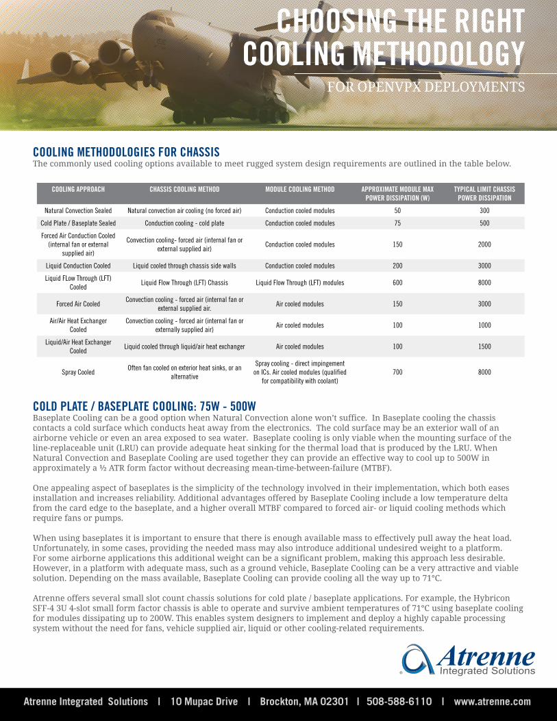
COOLING METHODOLOGIES FOR CHASSISThe commonly used cooling options available to meet rugged system design requirements are outlined in the table below.
COOLING APPROACH CHASSIS COOLING METHOD MODULE COOLING METHOD APPROXIMATE MODULE MAX POWER DISSIPATION (W)
TYPICAL LIMIT CHASSIS POWER DISSIPATION
Natural Convection Sealed Natural convection air cooling (no forced air) Conduction cooled modules 50 300
Cold Plate / Baseplate Sealed Conduction cooling - cold plate Conduction cooled modules 75 500
Forced Air Conduction Cooled (internal fan or external
supplied air)
Convection cooling- forced air (internal fan or external supplied air)
Conduction cooled modules 150 2000
Liquid Conduction Cooled Liquid cooled through chassis side walls Conduction cooled modules 200 3000
Liquid FLow Through (LFT) Cooled
Liquid Flow Through (LFT) Chassis Liquid Flow Through (LFT) modules 600 8000
Forced Air CooledConvection cooling - forced air (internal fan or
external supplied air.Air cooled modules 150 3000
Air/Air Heat Exchanger Cooled
Convection cooling - forced air (internal fan or externally supplied air)
Air cooled modules 100 1000
Liquid/Air Heat Exchanger Cooled
Liquid cooled through liquid/air heat exchanger Air cooled modules 100 1500
Spray CooledOften fan cooled on exterior heat sinks, or an
alternative
Spray cooling - direct impingement on ICs. Air cooled modules (qualified
for compatibility with coolant)700 8000
COLD PLATE / BASEPLATE COOLING: 75W - 500WBaseplate Cooling can be a good option when Natural Convection alone won’t suffice. In Baseplate cooling the chassis contacts a cold surface which conducts heat away from the electronics. The cold surface may be an exterior wall of an airborne vehicle or even an area exposed to sea water. Baseplate cooling is only viable when the mounting surface of the line-replaceable unit (LRU) can provide adequate heat sinking for the thermal load that is produced by the LRU. When Natural Convection and Baseplate Cooling are used together they can provide an effective way to cool up to 500W in approximately a ½ ATR form factor without decreasing mean-time-between-failure (MTBF).
One appealing aspect of baseplates is the simplicity of the technology involved in their implementation, which both eases installation and increases reliability. Additional advantages offered by Baseplate Cooling include a low temperature delta from the card edge to the baseplate, and a higher overall MTBF compared to forced air- or liquid cooling methods which require fans or pumps.
When using baseplates it is important to ensure that there is enough available mass to effectively pull away the heat load. Unfortunately, in some cases, providing the needed mass may also introduce additional undesired weight to a platform. For some airborne applications this additional weight can be a significant problem, making this approach less desirable. However, in a platform with adequate mass, such as a ground vehicle, Baseplate Cooling can be a very attractive and viable solution. Depending on the mass available, Baseplate Cooling can provide cooling all the way up to 71°C.
Atrenne offers several small slot count chassis solutions for cold plate / baseplate applications. For example, the Hybricon SFF-4 3U 4-slot small form factor chassis is able to operate and survive ambient temperatures of 71°C using baseplate cooling for modules dissipating up to 200W. This enables system designers to implement and deploy a highly capable processing system without the need for fans, vehicle supplied air, liquid or other cooling-related requirements.
FOR OPENVPX DEPLOYMENTS
CHOOSING THE RIGHTCOOLING METHODOLOGY
AtrenneIntegrated Solutions

Atrenne Integrated Solutions | 10 Mupac Drive | Brockton, MA 02301 | 508-588-6110 | www.atrenne.com
FORCED AIR CONDUCTION: 150W-2000W
Forced Air Conduction cooling has been proven to cool up to 2000W and is one of the most popular design approaches for rugged deployed applications. Forced Air Conduction cooling shares some characteristics with Natural Convection cooling. Both use a sealed internal chassis structure and fins to conduct heat to cooling air. With Natural Convection cooling, large wide fins can be used, but forced air conduction requires narrow fins and the addition of an outside wall to close off the cooling channels. Combined, these features required for Forced Air conduction cooling add weight, complexity and lead time (additional time for chassis design).
The air blown by the chassis fans never touches the modules in Forced Air conduction cooling. It passes through a duct with fins that draw heat from the sidewall that contacts the cold rails of the conduction cooled modules. The chassis are constructed to provide a cold sidewall to the top and bottom of the OpenVPX card. The need to supply forced cooling to two sidewalls can be a challenge. A fan can be placed at the back of the chassis, but because the air needs to be directed into the flow channels along each sidewall the result can be a large pressure drop as the air is forced to bend around corners.
Choosing the right type of fan is critical. Rugged military grade fans can be more costly (than industrial grade) and require long lead times. This makes it important to run thermal simulations, e.g., computational fluid dynamics (CFD), on the cooling design, not just once but perhaps several times as the design matures. The results can then be compared to that of the fan’s curve performance, to help determine if pressure or flow rates must be increased, and if changes to the chassis structure are needed. This process of matching the fan to the system flow is iterative and can be time consuming.
A significant advantage of fan cooling is that fans can achieve lower board temperatures that extend the functional life of the electronic components. Being able to run a processor at a die temperature of 75°C instead of 100°C may make a significant difference in overall system reliability.
A concern associated with the use of fans is the noise level they create. This is particularly of concern during lab (or office) development. Atrenne has developed fan cooled systems with integrated fan speed control that adjusts the fan speed in accordance with the ambient temperature. Fans are typically chosen to provide the cooling needed at conditions when the unit is operating at maximum power and maximum ambient temperatures such as at 71°C. In the laboratory, where temperatures are typically around 24°C, the high performance range of the fans is not required and the fans can be slowed down without affecting the performance of the unit. Another advantage of this approach is that the fans can be slowed down in the field when ambient conditions are not at their worst, to reduce overall power consumption. This may be particularly important on airborne platforms or ground vehicles where power budgets are usually limited.
Atrenne offers several large and small slot count chassis solutions for forced air conduction applications. Forexample, the application specific Hybricon® 79-182 High Power OpenVPX ATR enclosure was designed based on a customer’s requirements for a UAV ISR application. The enclosure is a 1-1/2 ATR chassis designed to perform at 0-35,000 ft. and -40°C to +40°C environment. The chassis supports 28V DC input with a MIL-STD-704F 1569W power supply. The 1-1/2 ATR enclosure is forced air cooled with
AtrenneIntegrated Solutions
FOR OPENVPX DEPLOYMENTS
CHOOSING THE RIGHTCOOLING METHODOLOGY
Hybricon SFF-6 3U 4-slot baseplate cooled chassisCFD Simulation of Forced Air Conduction ATR with
High Power 6U OpenVPX 100-150W/slot

Atrenne Integrated Solutions | 10 Mupac Drive | Brockton, MA 02301 | 508-588-6110 | www.atrenne.com
Cooling can only be used on platforms which already support liquid cooling infrastructure. Atrenne offers several chassis solutions for liquid
conduction-cooled boards. The active backplane supports ten 6U OpenVPX slots and two 3U OpenVPX slots of 1.0” pitch plus one Power Supply slot and interfaces to an I/O panel circuit card assembly (CCA).
LIQUID CONDUCTION COOLED: 200W-3000W
FOR OPENVPX DEPLOYMENTS
CHOOSING THE RIGHTCOOLING METHODOLOGY
CFD Simulation of Liquid Conduction ATR with High Power 6U OpenVPX
Hybricon 79-182 3U/6U OpenVPX Forced Air Conduction Chassis
With Liquid Conduction Cooling, up to 50% more cooling capacity can be achieved over what is possible with Forced Air Conduction Cooling. Liquid Conduction Cooling and Forced Air Conduction Cooling also share the same basic internal chassis structure. With Liquid cooling, the chassis will have quick disconnect liquid couplings attached to sidewalls or the front panel through which externally supplied cooling liquid flows in and out of fluid passages in the chassis walls. The chassis walls have flow channels that often are optimized based on the application requirements for cooling as well as pressure drop. With no direct reliance on pressurized air, the Liquid Conduction Cooled approach is much less sensitive to altitude than air-cooled ruggedization methodologies. Also, the ability to cool 3KW allows Liquid Conduction Cooling to be suitable for very high-powered processor and FPGA DSP modules such as are used in high-performance embedded computing (HPEC). For these reasons, Liquid Conduction Cooled chassis are often used in C4-ISR sensor processing applications in the most environmentally demanding airborne platforms.
Compared to the previous approaches discussed, Liquid Conduction Cooling is often considered to be significantly more complex, but an experienced design team can lower the risk and increase the reliability of using Liquid coolants. Several key performance parameters must be considered: selection of fluid couplings (typically quick disconnect or QD type), corrosion, fluid type, fluid flow rate, fluid pressure drop and supply fluid temperature. It is important to run computational fluid dynamics (CFD) on the cooling design, not just once but several times as the design matures. Practically speaking, Liquid Conduction
conduction applications. For example, the Hybricon® 63-173 application specific OpenVPX 1-ATR enclosure was designed based on a customer’s requirements for a high power ISR application. The enclosure is a 1 ATR long card cage with 2.7k Watt power supplies. The application specific 6U OpenVPX backplane includes 13 slots for 6U OpenVPX modules, 10 Gbaud OpenVPX Gen 3 signaling requirements, and three 6U VITA 62 power supply slots. The chassis also includes 28V DC MIL-STD-704F input power, VPX+ RTM I/O cabling, and top hat features to allow bend radius for I/O from module faceplates. The chassis is cooled utilizing EGW coolant with Quick Disconnect couplings.
Hybricon 63-173 1 ATR Long Liquid Conduction Chassis
AIR/AIR HEAT EXCHANGER COOLED: 100W-1000WWith Air/Air Heat Exchanger Cooling, the chassis has a dedicated path with cooling fans for external ambient air that flows through an air/air heat exchanger. Internal air is re-circulated through the other side of the air/air heat exchanger and then over the payload modules. Ambient air does not flow over the payload modules. It is used to cool the internal air via the air/air heat exchanger. This avoids

www.atrenne.com800.926.8722
AtrenneIntegrated Solutions
Atrenne Integrated Solutions | 10 Mupac Drive | Brockton, MA 02301 | 508-588-6110 | www.atrenne.com
ATR Chassis Solution 63-173
• 1+ ATR 13-slots, OpenVPX, 6U
• Liquid-cooled chassis/EGW
• Conduction-cooled modules
• Operating temperature -40 to +85C
• 0 to 50,000 ft. MSL
• Input 28 VDC, MIL-STD-704F
• 2700W power supply; can power and cool >200W per slot
ATR Chassis Solution 78-710
• 1+ ATR 10-slots 6U• Liquid-cooled chassis / variety of cooling fluids• Conduction-cooled modules
• Operating temperature -40 to +70C
• -1,500 to 60,000 ft. MSL• 1-2 Power Supply Slots
ATR Chassis Solution 99-193
• 1+ ATR Short, 7-slots, 6U
• Liquid-cooled chassis
• Conduction-cooled modules
• Operating temperature -40 to +60C
• Shock per MIL-STD-810
• Input 3-phase 400 Hz MIL-STD-704A, 750W
• Cooling for >150W per slot
• 1-2 Power Supply Slots
ATR Chassis Solution 688-00
• 1/2 ATR Tall Long, 14-slots, Hybrid 3U/6U
• Air-cooled chassis with air-to-air heat exchanger
• Air-cooled modules, 10 CFM
• Operating temperature 0 to 55C
• Three 3U 28 VDC-input pluggable power supplies, 1050W
ATR Chassis Solution 881-131
• 3/4 ATR Short, Small Form Factor 7-slots 3U
• Baseplate-cooled chassis
• Conduction-cooled modules
• Operating temperature -40 to 55C
• 0 to 28,000 ft. MSL
• Input 28 VDC MIL-STD-704F and MIL-STD-1275B, 450W
OUR NAME BEGINS WITH ATR

Atrenne Integrated Solutions | 10 Mupac Drive | Brockton, MA 02301 | 508-588-6110 | www.atrenne.com
any concern with particulates in the external environment affecting module operation while retaining the simplicity and flexibility of an air-cooled approach.
Atrenne offers chassis solutions for air/air heat exchanger applications. For example, the Hybricon® 668-00 Air- Cooled 1-1/2 ATR Tall Air-Air Heat Exchanger Chassis is an application-specific enclosure that includes a 14-slot Hybrid 3U/6U backplane and a 500W power supply. The chassis, designed to operate in a temperature range of 0C to +55C, is part of Atrenne’s industry-leading Hybricon line of engineered packaging solutions that feature innovative design for dependable operation in today’s data-intensive, rugged aerospace and military applications.
AtrenneIntegrated Solutions
Atrenne offers several chassis solutions for rugged liquid/air heat exchanger ATR applications. An example of this type of chassis is the Hybricon® 61-174 ruggedized application-specific ATR solution. This is a liquid convection-cooled ATR for airborne applications at up to 20,000 feet. It includes a rugged top load 3U/6U 10-slot air-cooled card cage, liquid-to-air heat exchanger, recirculating internal cooling air with two high altitude MIL type fans. It supports 8x 6U OpenVPX slots and 2x 3U OpenVPX slots of 1.0” pitch, with a 900 Watt liquid-cooled MIL-STD-704F 3-phase 400Hz power supply.
FORCED AIR COOLED: 150W-3000WWith Forced Air Cooling, the chassis is cooled by external ambient or ducted air that flows directly over the payload modules. Because it utilizes air cooled modules and those modules are directly cooled by ambient air, this approach is less rugged mechanically than framed conduction cooled module, but it is widely used in pressurized aircraft applications, shipborne below deck applications, as well as many ground sheltered and transit case environments. Forced Air Cooling is capable of cooling very high power payloads at low to medium altitudes.
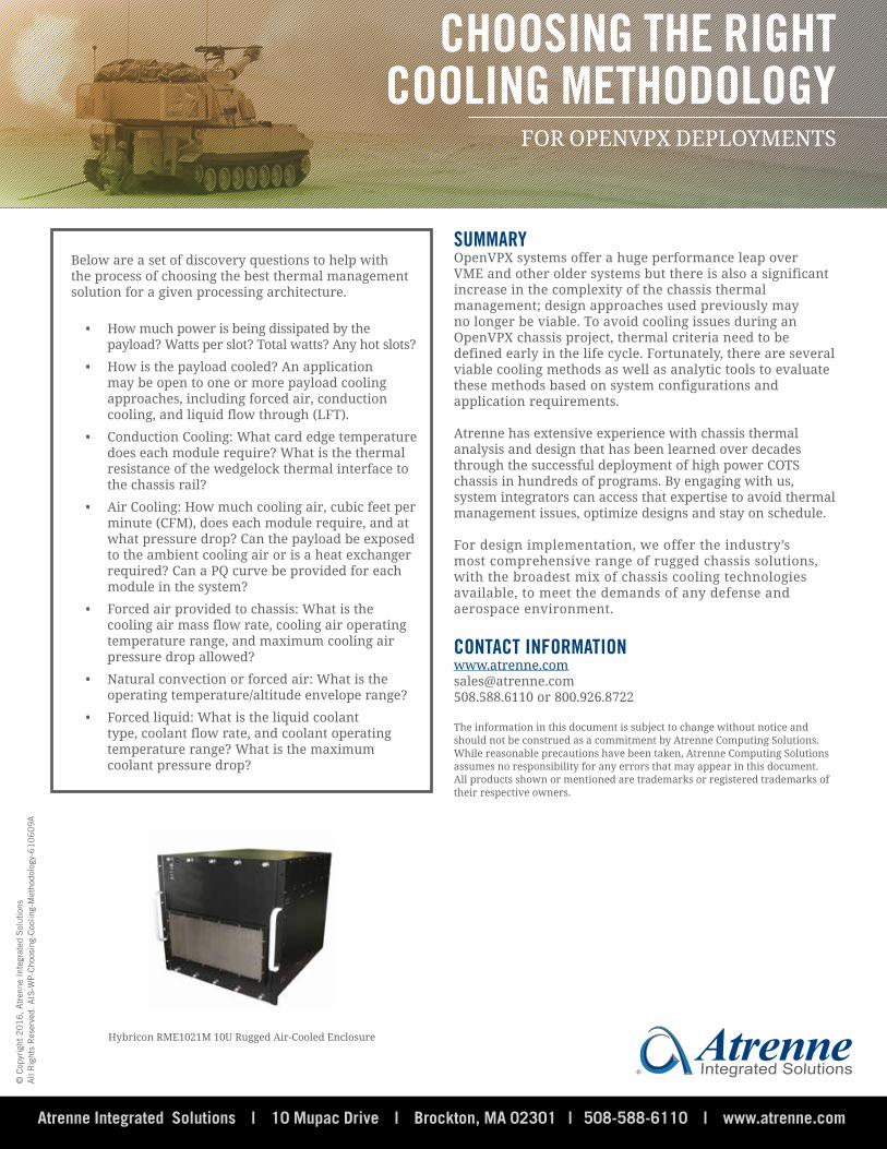
Atrenne offers a large number of chassis solutions for rugged air cooled rack-mount and ATR applications. For example, the Hybricon® Air-Cooled RME1021M is a 10U high, rackmount enclosure designed to cool very high-powered CPU and DSP boards. It has a 2400W 220V power supply with high-powered fans for cooling high-performance payload boards. It can support a VPX, VME, VXS or CompactPCI backplane.
FOR OPENVPX DEPLOYMENTS
CHOOSING THE RIGHTCOOLING METHODOLOGY
Hybricon 688-00 1-1/2 ATR Tall Air/Air Heat Exchanger Chassis
Thermal Simulation of Air-Air Heat Exchange Rugged ATR Chassis
Hybricon 61-174 ATR OpenVPX Heat Exchanger Chassis
LIQUID/AIR HEAT EXCHANGER COOLED: 100W-1500WWith Liquid/Air Heat Exchanger Cooling, the chassis has quick disconnect liquid couplings for externally supplied cooling liquid flowing in and out of the chassis liquid/air heat exchanger. Internal air is re-circulated through the liquid/air heat exchanger and over the payload modules. This approach also avoids any concern with particulates in the external environment affecting module operation. Because it utilizes air cooled modules, this approach is less mechanically rugged than the approaches above that utilize conduction cooled modules, but it has been successfully deployed in fighter jet pod applications along with an isolated ATR tray.
Atrenne Integrated Solutions | 10 Mupac Drive | Brockton, MA 02301 | 508-588-6110 | www.atrenne.com
Below are a set of discovery questions to help with the process of choosing the best thermal management solution for a given processing architecture.
• How much power is being dissipated by the payload? Watts per slot? Total watts? Any hot slots?
• How is the payload cooled? An application may be open to one or more payload cooling approaches, including forced air, conduction cooling, and liquid flow through (LFT).
• Conduction Cooling: What card edge temperature does each module require? What is the thermal resistance of the wedgelock thermal interface to the chassis rail?
• Air Cooling: How much cooling air, cubic feet per minute (CFM), does each module require, and at what pressure drop? Can the payload be exposed to the ambient cooling air or is a heat exchanger required? Can a PQ curve be provided for each module in the system?
• Forced air provided to chassis: What is the cooling air mass flow rate, cooling air operating temperature range, and maximum cooling air pressure drop allowed?
• Natural convection or forced air: What is the operating temperature/altitude envelope range?
• Forced liquid: What is the liquid coolant type, coolant flow rate, and coolant operating temperature range? What is the maximum coolant pressure drop?
SUMMARYOpenVPX systems offer a huge performance leap over VME and other older systems but there is also a significant increase in the complexity of the chassis thermal management; design approaches used previously may no longer be viable. To avoid cooling issues during an OpenVPX chassis project, thermal criteria need to be defined early in the life cycle. Fortunately, there are several viable cooling methods as well as analytic tools to evaluate these methods based on system configurations and application requirements.
Atrenne has extensive experience with chassis thermal analysis and design that has been learned over decades through the successful deployment of high power COTS chassis in hundreds of programs. By engaging with us, system integrators can access that expertise to avoid thermal management issues, optimize designs and stay on schedule.
For design implementation, we offer the industry’s most comprehensive range of rugged chassis solutions, with the broadest mix of chassis cooling technologies available, to meet the demands of any defense and aerospace environment.
CONTACT [email protected] or 800.926.8722
The information in this document is subject to change without notice and should not be construed as a commitment by Atrenne Computing Solutions. While reasonable precautions have been taken, Atrenne Computing Solutions assumes no responsibility for any errors that may appear in this document. All products shown or mentioned are trademarks or registered trademarks of their respective owners.
AtrenneIntegrated Solutions
© C
opyr
ight
20
16
, A
tren
ne I
nteg
rate
d S
olut
ions
All
Rig
hts
Res
erve
d. A
IS-W
P-C
hoos
ing-
Coo
ling-
Met
hodo
logy
-61
06
09
A
FOR OPENVPX DEPLOYMENTS
CHOOSING THE RIGHTCOOLING METHODOLOGY
Hybricon RME1021M 10U Rugged Air-Cooled Enclosure