chip pattern, burr and surface roughness in laser assisted micro ...jmes.ump.edu.my/images/volume 12...
TRANSCRIPT

Journal of Mechanical Engineering and Sciences
ISSN (Print): 2289-4659; e-ISSN: 2231-8380
Volume 12, Issue 1, pp. 3410-3430, March 2018
© Universiti Malaysia Pahang, Malaysia
DOI: https://doi.org/10.15282/jmes.12.1.2018.10.0304
3410
Chip pattern, burr and surface roughness in laser assisted micro milling of
Ti6Al4V using micro ball end mill
Z. Mohid1*
and E.A. Rahim1
1 Precision Machining Research Centre (PREMACH), Faculty of Mechanical &
Manufacturing Engineering, Universiti Tun Hussein Onn Malaysia *Email: [email protected]
Phone: +6075438441; Fax: +6074536080
ABSTRACT
The effectiveness of laser heating could easily fluctuates when the uncut chip thickness
are extremely inconsistent. In the case of using micro ball end mill tool, rubbing
mechanism is inevitable due to its radial shape geometry. Furthermore, the scenario
could be worst when the workpiece is a ductile material which has low thermal
conductivity such as Ti6Al4V. Thus, characterization study was carried out to evaluate
the feasibility of micro ball end mill in laser assisted micro milling operation. The chip,
burr and surface roughness from conventional and laser assisted micro milling were
compared and discussed. It is understood that the chip pattern indirectly gives
significant influence to the effectiveness of laser assisted micro milling technique. With
tool edge radius of 2 × 10⁻³
mm, feed value of 3.0 × 10⁻³
mm produced more consistent
surface roughness compared to feed value of 2.1 and 4.2 × 10⁻³
mm. The machining
parameters which produced continuous and conical chips ended up with sever burr
formation and surface roughness inconsistency.
Keywords: Laser assisted micro milling; chip pattern; burr; surface roughness; Ti6Al4V
INTRODUCTION
Laser assisted machining technique combines heating process and milling process
to allow the removal process to be done under preheated state [1, 2]. This technique
is reported effective in machining of difficult-to-machine materials with high
hardness [3, 4]. Heating the workpiece helps to reduce the hardness and maximum
temperature increment caused by shearing and friction mechanisms. The workpiece
properties are temporarily modified, allowing the milling process done under lower
mechanical and thermal load. The machining process managed to be done under
lower cutting force and cutting temperature [5, 6], thus improve machining surface
quality and tool life.
However, this technique has comparatively larger number or process
influencing factors which leads to performance inconsistency [4]. The machining
performance could fluctuates by two major categories of parameters namely laser
heating and milling process. Laser heating parameters such as laser power, laser
beam diameter and power intensity distribution modes contribute largely to
temperature distribution characteristics [7]. The achievable heating temperature at
cutting area will finally determine the level of softening effect at cutting area. On
the other hand, Milling parameters such as feed per tooth (f), depth of cut (tc) and

Chip pattern, burr and surface roughness in laser assisted micro milling of Ti6Al4V using
micro ball end mill
3411
cutting speed (vc) determine the removal process mechanism by altering the value
of uncut chip thickness and the temperature at the cutting area [8, 9].
Laser assisted milling/ micro milling on various materials including titanium
alloy has been reported with significant improvement. Most of the study used flat
end mill and insert cutting tools [10-14] and generally focused on the cutting force
and tool wear characteristics. Recent study in laser assisted milling using ball mill tool
were also reported but using macro size tools and not focused on titanium alloy as the
workpiece [14-18]. Furthermore, less has been reported on the effect of machining
parameters to the chips formation mechanism and machining quality in laser assisted
micro ball milling process.
The study on laser assisted micro machining performance using micro ball end
mill tool was firstly reported by Melkote et al. [1]. In the study, Ytterbium doped
continuous wave near IR (1.06 mm) fibre laser with diameter and laser power of ~0.16
mm and 7 W respectively was used as the laser source. Four flutes micro ball mill with
diameter of 0.25 mm was used to perform machining on hardened A2 steel. Lower
surface roughness, lower tool wear rate and better dimensional accuracy were obtained
with the assist of laser heating.
In the case of micro ball end mill, geometrical factors expose the removal
process to intense rubbing and ploughing effect [19, 20]. Furthermore, the chips
evacuation efficiency in laser assisted micro milling could be worst when the material is
heated, softened and more ductile [8]. Due to the tool geometrical factor, the chips are
formed in complicated shapes by multiple of strain vectors and tends to remain in the
cutting area. Forces act in multiple directions and the high gradient of cutting velocity
produces variant of strain rate in the cutting zone leading to poor surface roughness
[21]. In addition, tool size effect and minus rake angle [8] predominantly give influence
to chip formation characteristics and cutting performance when the tool is in micro scale
size.
Long chips should be avoided to prevent entanglements around the cutting area
which could lead to cutting tool and cutting surface damages [22]. Continuous and
excessive ploughing mechanism promotes temperature rise at the cutting zone which
consequently increases the tool wear rate [23]. Burr formation is another problem that
need to be considered when the material is heated and softened due to tearing failure
during the removal process [24]. At the tool bottom, comparatively large cutting edge
radius induce peculiar effects, erratic force variation and causing extensive burr
formation [25].
To produce machining surface with a consistent and small roughness,
understanding the actual mechanism occur during the machining process is
crucially important. Small uncut chip thickness tends to produce inconsistent
surface roughness due to ploughing and elastic recovery which finally generate
uneven plastic flow [26]. Considering that titanium alloy possesses low thermal
conductivity, machining this alloy using laser assisted micro ball end mill could
adversely worsen the machining performance. Localised heat increment could
promotes tool wear rate when the heat is continuously conducted from the
workpiece to the cutting tool [27-29].
This study was carried out to investigate the feasibility of laser assisted
micro milling when using micro ball end mill on ductile (Ti6Al4V) material. A new
approach was implemented to minimise the effect of ploughing and rubbing mechanism
and to eliminate large temperature gradient at the machining area. The tool was set in
tilted orientation and relatively large laser irradiation spot diameter was applied. The

Mohid et al. / Journal of Mechanical Engineering and Sciences 12(1) 2018 3410-3430
3412
feasibility of micro ball end mill in laser assisted micro milling operation through chip
pattern, burr and machining surface condition. The effect of laser heating to the chip
formation and machining surface conditions were evaluated by comparing between
conventional and laser assisted micro milling.
EXPERIMENTAL SETUP
Laser beam head is placed at the inclination angle (θi) of 55° from X-Y plane in Y-Z
plane direction as shown in Figure 1. A laser focusing head with focal length and
focusing diameter of 60 mm and 0.700 mm respectively was applied. The tool was
placed at the inclination of 80° from X-Y plane in X-Z plane direction to minimise
the forces generated during the cutting process [30]. All experiments were
conducted under stagnant air and controlled room temperature of 28 °C.
Figure 1. Micro milling tool and laser beam orientation
Table 1. Milling parameters
f × 10-3
(mm/flute) tc (mm) [vc (m/min)/fr(mm/min)]
2.1, 3.0 & 4.2 0.020 [7.6/52.5],[ 10.6/74] & [ 15.1/105]
0.045 [9.7/75],[ 13.6/105] & [19.4/150]
0.070 [10.9/105],[ 15.3/147] & [21.8/210]
In this study, two flute TiAlN coated cemented carbide micro ball mill with
diameter of 0.3 mm was used to produce grooves. Linear grove machining with
length of 25 mm/path was performed on Ti6Al4V plate with thickness, width and
length of 1.8, 25 and 40 mm respectively. The machining process were performed
using variable feed (f), cutting speed (vc) and depth of cut (tc) in both machining
techniques; conventional (Conv. µMill) and laser assisted micro milling (LAµMill)
(Table 1). In Conv. µMill, the workpiece temperature was controlled at 28 °C, while
the workpiece temperature in LAµMill varied by the laser heating parameters
applied.
The 80° of tool inclination from X-Y plane has made the tool effective diameter
(Øt_effect.) become 0.193, 0.247 and 0.248 mm at tc of 0.020, 0.045 and 0.070 mm
respectively (Figure 2). To perform machining with three levels of f of 2.1, 3.0 and 4.2
55 80
xy
Xt-b
tc
T
feed
direction
f
f
T
tc
Xt-b
: feed
: surface temperature
: depth of cut
: Tool to laser beam distance

Chip pattern, burr and surface roughness in laser assisted micro milling of Ti6Al4V using
micro ball end mill
3413
× 10-3
mm/flute, three spindle rotation (N) of 12.5, 17.5 and 25.0 × 10³ rpm were
applied. The value of vc were taken from the maximum values obtained from calculation
using the Øt_effect. and N applied. This configuration has made the vc varied by tc values.
At tc of 0.020 mm, different N values of 12.5, 17.5 and 25.0 × 10³ rpm has made the
machining process performed at three different vc of 7.6, 10.6 and 15.1 m/min
respectively. At N of 12.5, 17.5 and 25.0 × 10³ rpm, increasing the tc to 0.045 mm
has increased the vc to three different value of 9.7, 13.6 and 19.4 m/min
respectively. At tc of 0.070 mm, three different vc of 10.9, 15.3 and 21.8 m/min
were recorded.
Figure 2. Relation between cutting speed (vc) and depth of cut (tc)
Table 2.Laser heating parameters in LAµMill
Items Values
Laser average power, Pavg (W)
Pulse on time, tp (ms)
Pulse repetition rate, fp (Hz)
Tool to laser beam distance, Xt-b (mm)
Tool orientation angle, θt (°)
Feed rate, fr (mm/min)
3.4
1.0
100
0.6
80
Refer Table 1
In LAµMill, the laser setting parameters are shown in Table 2. To avoid the
workpiece from the creation of heat affected zone (HAZ) and melted zone (MZ) in
LAµMill, a constant Pavg, tp and fp of 3.4 W, 1 ms and 100 Hz respectively were
applied. This laser heating parameters was confirmed applicable to heat the
workpiece with maximum temperature not exceeding 950 °C which is the Ti6Al4V
phase transformation temperature.
The distance between the laser beam centre and the cutting tool centre (Xt-b)
was set at 0.6 mm. A gap of 0.1 mm between the laser irradiated area and tool outer
diameter was applied to avoid direct laser irradiation onto the cutting tool,
workpiece drastic temperature fluctuation and workpiece material sputtering effect.
0.0
2 m
m
0.0
45
mm
0.0
7 m
m
Ball mill
cutting edge
Øt-effec. 3 (0.07) = 0.278 mm
Øt-effec. 2 (0.045) = 0.247 mm
Øt-effec. 1 (0.045) = 0.193 mmvc (0.07)
10°
vc (0.045)
vc (0.02)
Tool direction

Mohid et al. / Journal of Mechanical Engineering and Sciences 12(1) 2018 3410-3430
3414
The temperature of the area which has direct contact with the micro ball milling
cutting edges were determined by finite element method (FEM) simulation.
The simulation model was validated by results comparison with the
experiment using thermocouple embedded 0.05 mm under the workpiece surface at
three different laser irradiation feed rate of 52.5, 105 and 210 mm/min. Using the
validated model, the temperature history and distribution of of the heated surface at
the centre line of the irradiation path were recorded and used to estimate the
maximum temperature at the cutting area. The results has shown that at three levels
of tc, f and vc, the workpiece top surface temperature at the cutting area in LAµMill
were estimated between 128 and 178 °C. The estimated workpiece temperature at
different fr and tc are plotted in Figure 3.
Figure 3. Estimated workpiece temperature at the cutting area in LAµMill under
different fr and tc.
The chips produced and scattering on the workpiece were collected using
double side tape and carbon tape after the first machining path (Xc of 25 mm). High
magnification micro scope was used to observe the chips pattern differences
between different machining parameters. Scanning electron microscope was used
for better image quality and larger magnification ratio. The width and length of
single chips were measured randomly from the chips with good orientation and
measurable. The chips thickness was not able to be measured due to the difficulty
to get the measurable orientation.
The burr and cutting surface topography were observed under SEM while
the cutting surface roughness was measured using table top roughness measuring
machine. Sampling length (λc), sampling size (In) and stylus tip radius (rtip) of 0.08,
0.4 and 0.002 mm respectively were applied for the roughness measurement,
according to the EN ISO 4288 standard. The surface roughness of three locations at
the machining groove (entrance, middle and exit side) were measured and averaged.
0.40 0.45 0.50 0.55 0.60 0.65 0.70 0.75 0.800
50
100
150
200
250
300
350
400
vs = 52.5 mm/min, f
p = 100 Hz, t
p = 1 ms, P
avg = 3.4
C1
A
C
0.40 0.45 0.50 0.55 0.60 0.65 0.70 0.75 0.800
50
100
150
200
250
300
350
400
vs = 52.5 mm/min, f
p = 100 Hz, t
p = 1 ms, P
avg = 3.4
C1
A
C
0.40 0.45 0.50 0.55 0.60 0.65 0.70 0.75 0.800
50
100
150
200
250
300
350
400
vs = 105 mm/min, f
p = 100 Hz, t
p = 1 ms, P
avg = 3.4 W
C1
A
C1
0.40 0.45 0.50 0.55 0.60 0.65 0.70 0.75 0.800
50
100
150
200
250
300
350
400
vs = 210 mm/min, f
p = 100 Hz, t
p = 1 ms, P
avg = 3.4 W
C1
A
C1
Sim
ula
ted S
urf
ace
Tem
per
ature
, T
(°C
)
Distance from laser irradiation center, X (mm)
0.075 mm
0.127 mm
135 C
157 C
178 C
tc = 0.070 mm
tc = 0.020 mm
Ball mill
Ø 0.300mm
165 C143 C
128 C
fr = 52.5 mm/min fr = 105 mm/min fr = 210 mm/min
Pavg = 3.4 W, fp = 100 Hz, tp = 1 ms, θi = 55
0.107 mm tc = 0.045 mm
170 C
149 C
131 C
0.800.50 0.60 0.700.40
400
0
100
200
300

Chip pattern, burr and surface roughness in laser assisted micro milling of Ti6Al4V using
micro ball end mill
3415
RESULTS AND DISCUSSION
Chip Formation Characteristics Table 3 shows the distribution of each different chips pattern. Based on the observation on chips produced from different machining parameters and methods, the chips can be divided into three main categories: loose arc, conical and continuous.
From the table, it can be seen that at tc of 0.020 mm, loose arc chips were
produced when the feed (f) was 0.003 mm/flute. When the tc was 0.045 and 0.070 mm,
all f values produced chips mixed with continuous and conical chips. Less connected
chips were produced from Conv. μMill process when the f were 4.2 × 10⁻³
mm/flute. In addition, at f of 4.2 × 10⁻³
mm/flute, Conv. μMill produced continuous
chips only at tc of 0.020 mm (Figue 4-a and Figure 5-b). Increasing the f value has
consequently increased the uncut chip thickness and reduced the swept angle [31].
At tc of 4.2 × 10⁻³
mm/flute, the chips were formed with larger thickness and stiffer.
As a result, the chips were produced with consistence shape and less connected
compared to the lower f value. Even though the ball milling tool perform
interrupted cutting, the chips were connected by compression and heat generated
during the cutting process [32]. The connected chips become longer until certain
length and flew away for the increasing of weight and collation with work piece or
other chips.
Table 3. Chips pattern mapping
tc (mm) Machining
technique
f1 f2 f3
N1 N2 N3 N1 N2 N3 N1 N2 N3
0.020
Conv.
µMill © © © L L L C C ⃝
LAµMill ⃝ ⃝ ⃝ ⃝ L L © © ©
0.045
Conv.
µMill C C C © © © C L C
LAµMill ⃝ ⃝ ⃝ © © © © © ©
0.070
Conv.
µMill © © © C C C C C C
LAµMill © © © C C C C C ©
N1, N2, N3 : 12.5 x 10³, 17.5 x 10
3, 25.0 x 10
3 (rpm)
f1, f2, f3 : 2.1 × 10⁻³
, 3.0 × 10⁻³
, 4.2 × 10⁻³
mm/flute
⃝ : mixed with continuous chips
© : mixed width continuous and conical chips
C : conical chips
L : only loose arc chips

Mohid et al. / Journal of Mechanical Engineering and Sciences 12(1) 2018 3410-3430
3416
Conv. μMill, f = 2.1 × 10
-3 mm/flute
LAµMill, f = 2.1 × 10
-3 mm/flute
Figure 4. Chips pattern from Conv. μMill and LAµMill under different tc and vc
when f is 2.1 × 10⁻³
mm/flute
t c=
0.0
70
mm
t c=
0.0
45
mm
t c=
0.0
20
mm
0.1mm
vc = 10.9 m/min vc = 15.3 m/min vc = 21.8 m/min
vc = 9.7 m/min vc = 13.6 m/min vc = 19.4 m/min
vc = 7.6 m/min vc = 10.6 m/min vc = 15.1 m/min
t c=
0.0
70 m
mt c
= 0
.045 m
mt c
= 0
.020 m
m
0.1mm
vc = 10.9 m/min vc = 15.3 m/min vc = 21.8 m/min
vc = 9.7 m/min vc = 13.6 m/min vc = 19.4 m/min
vc = 7.6 m/min vc = 10.6 m/min vc = 15.1 m/min

Chip pattern, burr and surface roughness in laser assisted micro milling of Ti6Al4V using
micro ball end mill
3417
Conv. μMill, f = 4.2 × 10
-3 mm/flute
LAµMill, f = 4.2 × 10
-3 mm/flute
Figure 5. Chips collected from Conv. μMill and LAµMill under different tc and vc
when f is 4.2 × 10⁻³
mm/flute
t c=
0.0
70
mm
t c=
0.0
45
mm
t c=
0.0
20
mm
0.1mm
vc = 10.9 m/min vc = 15.3 m/min vc = 21.8 m/min
vc = 9.7 m/min vc = 13.6 m/min vc = 19.4 m/min
vc = 7.6 m/min vc = 10.6 m/min vc = 15.1 m/min
t c=
0.0
70
mm
t c=
0.0
45
mm
t c=
0.0
20
mm
0.1mm
vc = 10.9 m/min vc = 15.3 m/min vc = 21.8 m/min
vc = 9.7 m/min vc = 13.6 m/min vc = 19.4 m/min
vc = 7.6 m/min vc = 10.6 m/min vc = 15.1 m/min
Mohid et al. / Journal of Mechanical Engineering and Sciences 12(1) 2018 3410-3430
3418
On the other hands, when the f was 2.1 × 10⁻³
mm/flute, the uncut chip
thickness were approximately equal to the tool tip radius. When the uncut chip
thickness is equal or less than tool tip radius, the chips will be formed under uneven
plastic flow with high ratio of rubbing and ploughing effect due to minus rake angle
cutting edge [26, 33]. Ploughing and rubbing effect has consequently produced thin
and connected chips, and inconsistent in shape and size. Generally, increasing the f
value from 0.0021 to 0.0042 mm/flute has changes the chips from continuous to
conical.
Increasing the vc in the range between 7.6 m/min to 21.8 m/min was unable to
show different chip formation characteristics as reported by Sun et al. [29]. No sharp-
teeth and sharp segmented chip were identified. The vc increment were found does not
have significant relation with the chip creation characteristics. The chips produced in
this study were comparatively too thin and small. The chips were formed under intense
plastic deformation and the segmentation distance was independent from cutting speed
changes.
It is also observed that the chips were also produced in the similar shape,
regardless to the vc applied in LAµMill. It is suggested that the temperature increment
initiated by the vc increment were not significant to give influence onto the chip
formation behaviour between the both machining techniques (Conv. μMill and
LAµMill). The shear and plastic deformation zone were extremely small and unable to
generate sufficient heat which can give influence to the workpiece physical properties
during the removal process.
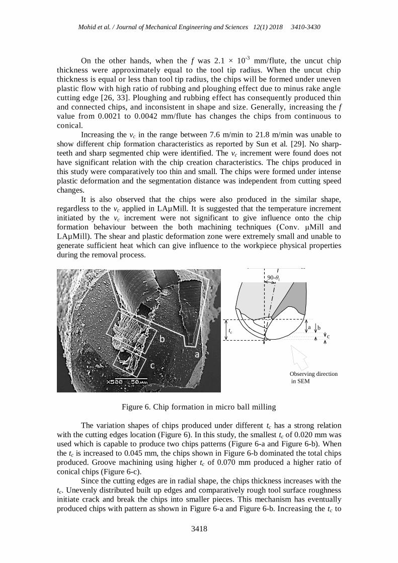
Figure 6. Chip formation in micro ball milling
The variation shapes of chips produced under different tc has a strong relation
with the cutting edges location (Figure 6). In this study, the smallest tc of 0.020 mm was
used which is capable to produce two chips patterns (Figure 6-a and Figure 6-b). When
the tc is increased to 0.045 mm, the chips shown in Figure 6-b dominated the total chips
produced. Groove machining using higher tc of 0.070 mm produced a higher ratio of
conical chips (Figure 6-c).
Since the cutting edges are in radial shape, the chips thickness increases with the
tc. Unevenly distributed built up edges and comparatively rough tool surface roughness
initiate crack and break the chips into smaller pieces. This mechanism has eventually
produced chips with pattern as shown in Figure 6-a and Figure 6-b. Increasing the tc to
a b c
c
b a tc
90-θi
c
b
a
Observing direction
in SEM

Chip pattern, burr and surface roughness in laser assisted micro milling of Ti6Al4V using
micro ball end mill
3419
0.070 mm has further increased the chip thickness and made the chips become
larger and stiffer. Consequently, the chips turn to conical as their length and width
become too large to fit in the space in front of the tool rake face. At this conditions,
the chips were compressed and bent by mechanical force to conical shapes.
LAµMill produced conical and elemental arc shape chips at tc of 0.045 and
0.070 mm. It is obviously can be seen that the chips produced form LAµMill is
larger and curlier compared to Conv. μMill (Figure 4-a). Larger chip size is one of
the evident that the chips flow out more easily due to lower tensile strength at
higher workpiece temperature [28].
Figure 7. Chips formation in LAµMill
(f = 3.0 × 10⁻³
mm/flute, tc = 0.020 mm, fr = 52.5 mm/min)
Figure 7 shows the evident of how the chips were formed in LAµMill.
Commonly, chips in LAµMill were created in ununiformed shapes. Higher percentage
of continuous and conical chips were produced and they were larger in size
compared to Conv. µMill. Even though the size of the chips was larger when the tc is
increased, less chips were produced in elemental arc shape. The conical chips were
connected to form continuous and thin chip. The thin and continuous chips adhered on
the cutting edge which performing the cutting process and they were located near to the
chisel area. From a single cutting edge, the chips were formed in various thickness and
patterns. When the material is heated, the chip size and shape can be more inconsistent
due to the increment of plastic behaviour and ductility. Elastic recovery thickness is
suggested one of the major reason [31]. Certain thickness of workpiece were left over
during the previous cut and removed together with the next tool engagement and created
thicker and different chip size and pattern. This phenomenon can be seen obviously at
the f of 2.1 × 10⁻³
mm/flute which is near to cutting tool tip radius (1~2 × 10⁻³
mm). In
addition, the heated workpiece has a higher tendency to produce continuous and snarled
a
b
a. Conical chip b. Connected chip
Mohid et al. / Journal of Mechanical Engineering and Sciences 12(1) 2018 3410-3430
3420
chips [34]. This type of chips frequently interfere the cutting process and gave
significant influence on the overall chips pattern.
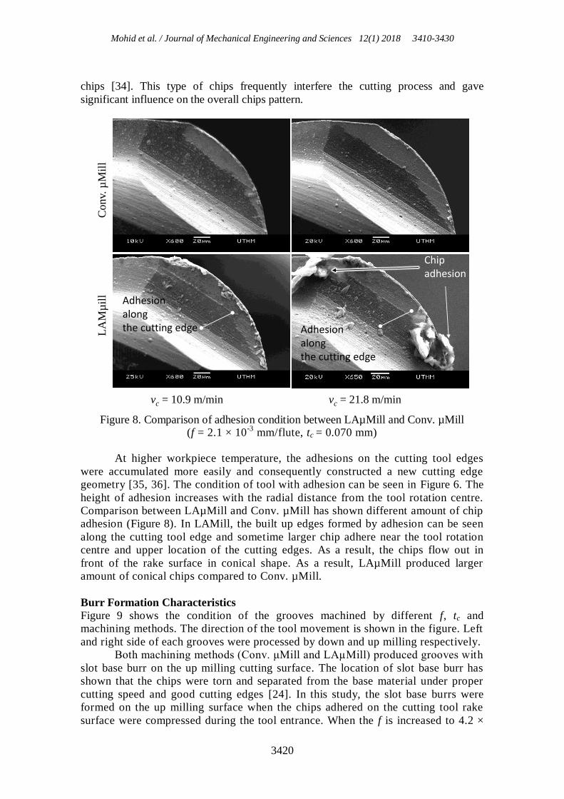
Figure 8. Comparison of adhesion condition between LAµMill and Conv. µMill
(f = 2.1 × 10⁻³
mm/flute, tc = 0.070 mm)
At higher workpiece temperature, the adhesions on the cutting tool edges
were accumulated more easily and consequently constructed a new cutting edge
geometry [35, 36]. The condition of tool with adhesion can be seen in Figure 6. The
height of adhesion increases with the radial distance from the tool rotation centre.
Comparison between LAµMill and Conv. µMill has shown different amount of chip
adhesion (Figure 8). In LAMill, the built up edges formed by adhesion can be seen
along the cutting tool edge and sometime larger chip adhere near the tool rotation
centre and upper location of the cutting edges. As a result, the chips flow out in
front of the rake surface in conical shape. As a result, LAµMill produced larger
amount of conical chips compared to Conv. µMill.
Burr Formation Characteristics
Figure 9 shows the condition of the grooves machined by different f, tc and
machining methods. The direction of the tool movement is shown in the figure. Left
and right side of each grooves were processed by down and up milling respectively.
Both machining methods (Conv. μMill and LAµMill) produced grooves with
slot base burr on the up milling cutting surface. The location of slot base burr has
shown that the chips were torn and separated from the base material under proper
cutting speed and good cutting edges [24]. In this study, the slot base burrs were
formed on the up milling surface when the chips adhered on the cutting tool rake
surface were compressed during the tool entrance. When the f is increased to 4.2 ×
LA
Mµ
ill
Conv.
µM
ill
vc = 10.9 m/min vc = 21.8 m/min
Chip adhesion
Adhesionalong the cutting edge Adhesion
along the cutting edge

Chip pattern, burr and surface roughness in laser assisted micro milling of Ti6Al4V using
micro ball end mill
3421
10-3
mm/flute, less slot base burr created (Figure 10). Ticker and stronger chips
were produced and flowed out from the cutting area more efficiently is suggested to
be the main reason. In addition, the milling process was performed under less
elastic deformation effect when the uncut chip thickness is larger than minimum
chip thickness [8] which need to be in range of 5 % to 38 % of the cutting edge
radius [37]. Consequently, fewer chips adhered on the up milling side surfaces.
Figure 10 shows the grooves fabricated using higher vc which ranged from 15.1
to 21.8 m/min. The groove conditions were not much different compared to Figure 9
which were produced under lower vc. Ploughing and rubbing effect dominated the
removal process mechanisms in the both vc ranges which consequently worsen the
cutting surface appearance [23, 38] at lower cutting speed, in LAµMill process and
Conv. µMill. Increasing the vc does not give significant effect on the burr condition at tc
of 0.020 and 0.045 mm. The amount of slot base burr at the up milling regions were
considerably equal.
However, significant difference on slot base burr condition between high and
low vc was observed at tc of 0.070 mm. The chips were produced in continuous and
conical shapes, and significantly larger than tc of 0.045 mm and 0.020 mm. At tc of
0.070 mm, the large size of chips compressed on the machining surface created slot
base burr and top burr at the up milling machining surface. Larger size of chip
compression at higher vc has consequently promoted the slot base bur formation due to
higher cutting temperature [35] generated via shearing and friction mechanisms
adhere on the tool cutting edges. At the same time, the grooves seemed to be larger
in LAµMill. It means that the grooves were produced deeper in LAµMill. The
actual tc become larger for the less tool edge positioning error [39], thus produced
larger amounts of conical shape chips. This type of chips were being compressed
onto the cutting groove up milling sides and remained as slot base burr.
The top burr at the down milling side was produced larger in LAµMill
compared to Conv. µMill. This burr was formed by plastic deformation during the
cutting process. LAµMill tends to produce continuous chips and rotating together with
the cutting tool. This phenomenon shows that LAµMill has a higher tendency for the
chips to adhere and blocking the cutting edges which contributes to inconsistence
machining performance [40]. The creation of larger top burr at the down milling
sides in LAµMill is a significant evidence showing that the workpiece being heated
has become softer. Consequently, more obvious plastic deformation occurs during
the cutting process. The formation of top burr are obvious at tc of 0.070 mm. It
indicates that the tc value is tool large since the ratio of axial depth of cut to ball
milling radius need to be considered in micro milling operation with ball end mill
tools [24].
Slot base burr were observed in the both machining techniques, Conv. µMill and
µLAMill. It is a normal phenomenon in micro machining of metal materials [41].
However in the case of this study, slot base burr which formed by chip compression
at the up milling side were found larger in LAµMill. It is suggested that, when the
workpiece is heated, the workpiece became softer and easier to

Mohid et al. / Journal of Mechanical Engineering and Sciences 12(1) 2018 3410-3430
3422
Figure 9. Machined grooves comparison between different tc, f and machining
methods with vc ranged from 7.6 to 10.9 m/min
LA
µM
ill
Conv.
µM
ill
LA
µM
ill
Conv.
µM
ill
f=
2.1
10
-3m
m/f
lute
f=
4.2
10
-3m
m/f
lute
down
millingup
milling
Tool
feed
dir
ecti
on
tc = 0.020 mm
vc = 7.6 m/min
tc = 0.045 mm
vc = 9.7 m/min
tc = 0.070 mm
vc = 10.9 m/min

Chip pattern, burr and surface roughness in laser assisted micro milling of Ti6Al4V using
micro ball end mill
3423
Figure 10. Machined grooves comparison between different tc, f and machining
methods with vc ranged from 15.1 to 21.8 m/min
Referring to the thermal dependant properties of Ti6Al4V, heating the
material from 20 C to 200 C will give softening effect to the workpiece. Young’s
modulus is expected to reduce from 114 to 105 × 105 (N·mm
-2) [42], while the
density will reduce from 4.42 to 4.39 × 10³
(Kg·mm3) [7]. Calcualtion using
modified Johnson Cook material model [23] estimated that the flow stress will
LA
µM
ill
Co
nv.
µM
ill
LA
µM
ill
Conv.
µM
ill
f=
2.1
1
0-3
mm
/flu
tef
= 4
.2
10
-3m
m/f
lute
tc = 0.020 mm
vc = 15.1 m/min
tc = 0.045 mm
vc = 19.4 m/min
tc = 0.070 mm
vc = 21.8 m/min
down
millingup
milling
To
ol
feed
dir
ecti
on

Mohid et al. / Journal of Mechanical Engineering and Sciences 12(1) 2018 3410-3430
3424
resuce for approximately 14 % when the material heated from 20 to 200 °C. The
properties changes occur during LAµMill has caused different chip formation and
machining characteristics between the two different machining techniques.
The difference in burr creation has shown that the micro ball end mill is
insufficient for deep grove machining. The chips produced at every tool engagement
need to be efficiently removed to avoid chip compression at the machining area.
Surface Roughness
Figure 11 shows the surface roughness (Ra) of the groove bottom surfaces. Alphabet C
and L represent the machining techniques used in the experiment (C: Conv. µMill, L:
LAµMill). The measurements were taken at three point; entrance, centre and exit part of
the machined grooves. The Ra values were compared between different machining
techniques under three different depth of cut (tc), three different feed (f) and various
cutting speeds (vc).
The Ra fluctuated and changed differently at different tc. At tc of 0.020 mm, Ra
increased with f. However, the increment was not significant. At f of 4.2 × 10⁻³
mm/flute, the Ra value fluctuated significantly larger than f of 2.1 and 3.0 × 10⁻³
mm/flute. Larger size of connected chips are suggested to be the major reason. The
connected chips generated at tc of 0.020 mm became thicker when the f is increased.
Low chip evacuation efficiency of connected chips is suggested to give influence to Ra
by tangling around the cutting area during the machining process.
The relation between f and Ra was unable to be seen at tc of 0.045 mm. There
were also less significant roughness different between f of 2.1 and 3.0 × 10⁻³
mm/flute.
It is suggested that the f values (2.1 and 3.0 × 10⁻³
mm/flute) were too close to the
cutting edge radius (1~2 × 10⁻³
mm), thus the cutting process was dominated by rubbing
and ploughing effect. In the case of tc of 0.070 mm, when the f was increased to 4.2 ×
10-3
mm/flute, the chips became thicker and stiffer which caused the connected chips to
be more easily to disconnected and flow out from the cutting area. This has caused the
Ra becomes more consistent at f of 4.2 × 10⁻³
mm/flute compared to 2.1 and 3.0 × 10⁻³
mm/flute when the tc was 0.070 mm.
The Ra fluctuation range increases with the tc. Larger volume of chips produce
per each tool engagement will consequently increase the forces act on the cutting tool. It
is suggested that larger and thicker chips involved in rubbing mechanism has caused
ploughing effect to be more influencing the machining surface condition. Rapid flank
wear propagation at larger tc also suggested to give significant effect to the Ra value. As
a result, higher tc produced larger Ra value fluctuation.
Overall, vc gave less significant influence to Ra value (Figure 11). However, the
Ra increases with fr when the f and tc were 2.1 × 10⁻³
mm/flute and 0.070 mm
respectively. For the reason that the tool cutting edges radius is approximately 2.0 × 10⁻³
mm, the process is dominated by rubbing mechanism [31]. Increasing the vc will
consequently enhance the effect of ploughing and plastics deformation. These has
caused the Ra value and fluctuation range to increase.
At higher f of 3.0 and 4.2 × 10⁻³
mm/flute, the increment of vc from 7.6 to 21.8
m/min did not gave significant Ra changing trend. The machining process was
performed under adiabatic shear mechanism which involved poor heat dissipation and
intense shear concentration [43-45]. The shear and deformation area is too small and
unable to generate significant temperature difference which could bring influence to the
Ra value via softening effect. Consequently, the value of Ra were kept approximately at
the same level even though the vc were increased to double.

Chip pattern, burr and surface roughness in laser assisted micro milling of Ti6Al4V using
micro ball end mill
3425
Figure 11. Surface roughness (Ra) for cutting distance (Xc) between 25 to 50 mm
when tc were 0.020 mm
One quarter of the parameters used in the study has shown larger Ra value when
laser heating is applied. LAµMill has generally shown larger Ra at tc of 0.070 mm.
Heating process in LAµMill has caused the workpiece became more ductile [5, 6] and
produced curly chips with inconsistence size and shape. This chips has higher tendency
to stick on the cutting surface by rubbing and ploughing mechanisms. A lot of chips
0 1 2 3 4 5 6 7 8 9 10 11 12 13 14 15 16 17 18 190.00
0.05
0.10
0.15
0.20
0 1 2 3 4 5 6 7 8 9 10 11 12 13 14 15 16 17 18 190.00
0.05
0.10
0.15
0.20
0 1 2 3 4 5 6 7 8 9 10 11 12 13 14 15 16 17 18 190.00
0.05
0.10
0.15
0.20
a. tc = 0.07 mm
Surf
ace
Ro
ug
hn
ess,
Ra (
m)
A
Surf
ace
Ro
ug
hn
ess,
Ra (
m)
A
c. tc = 0.02 mm
Surf
ace
Ro
ug
hn
ess,
Ra (
m)
A
b. tc = 0.045 mm
f = 2.1 10-3 mm/flute f = 3.0 10-3 mm/flute f = 4.2 10-3 mm/flute
Techniques
vc (m/min) 10.9 15.3 21.8
C L C L C L
10.9 15.3 21.8
C L C L C L
10.9 15.3 21.8
C L C L C L
Techniques
vc (m/min) 9.7 13.6 19.4
C L C L C L
9.7 13.6 19.4
C L C L C L
9.7 13.6 19.4
C L C L C L
Techniques
vc (m/min) 7.6 10.6 15.1
C L C L C L
7.6 10.6 15.1
C L C L C L
7.6 10.6 15.1
C L C L C L
f = 2.1 10-3 mm/flute f = 3.0 10-3 mm/flute f = 4.2 10-3 mm/flute
f = 2.1 10-3 mm/flute f = 3.0 10-3 mm/flute f = 4.2 10-3 mm/flute

Mohid et al. / Journal of Mechanical Engineering and Sciences 12(1) 2018 3410-3430
3426
were found sticking on the cutting surface near the groove centre line. This has made
the Ra to be larger than Conv. µMill.
The effect of laser heating to the reduction of Ra only can be observed at tc of
0.020 mm when the f were 3.0 and 4.2 × 10⁻³
mm/flute (Figure 11). The Ra value
reduced for approximately 12 % to 20 % when laser heating were applied. It is
suggested that lower material strength and better chips flow [46] compared to the tc of
0.070 mm has contributed largely to Ra reduction. Less Ra reduction was recorded at
higher vc value due to lower workpiece temperature achieved in LAµMill.
CONCLUSION
Through the experimental results, the feasibility of micro ball end mill in
LAµMill was successfully evaluated. LAµMill under heating temperature of 130 °C
to 180 °C has shown different machining characteristics. From the results of chips
formation characteristics, burr and surface conditions, the next conclusions are
derived.
Feed of 4.2 × 10⁻³
mm/flute produced the most consistent chips pattern with less
connected chip. In contrast, at feed of 2.1 × 10⁻³
mm/flute, most of the chips were
produced in continuous shape.
Cutting speed in range between 7.6 m/min and 21.8 m/min does not give significant
influence to the chip pattern and burr formation characteristics in the both
machining techniques (LAµMill and Conv. μMill).
Chips pattern show a strong relation with the machining surface roughness
consistency. Under the depth of cut of 0.020 mm, the feed value of 3.0 × 10⁻³
mm/flute has shown comparably consistent surface roughness under different cutting
speed. Loose arc chips produced at this machining parameter allows the machining
to be performed with less chip blocking, ploughing and rubbing mechanism which
consequently produced consistent surface roughness.
Machining under the depth of cut 0.045 and 0.070 mm has resulted to inconsistence
surface roughness at all feed value and cutting speed applied due to the existence of
connected and conical chips.
Laser heating in LAµMill promoted the slot base burr creation by increasing the
tendency of chip adhesion on cutting tool and the frequency of connected chip
creation.
Machining at tc of 0.045 and 0.070 mm are not recommended for the both
machining techniques (Conv. µMill and LAµMill) due to excessively large chip
size. Severe chips compression and poor chip flow led to serious burr formation and
poor surface roughness.
ACKNOWLEDGEMENTS
This study is supported by the funding from the Ministry of Science Technology
and Innovation (MOSTI) of Malaysia under Science Fund Research Grant, vot number
S020. It is also supported by the SLAB/SLAI scholarship from the Ministry of High
Education of Malaysia and Universtiti Tun Hussein Onn Malaysia.

Chip pattern, burr and surface roughness in laser assisted micro milling of Ti6Al4V using
micro ball end mill
3427
REFERENCES
[1] Melkote S, Kumar M, Hashimoto F., Lahoti G. Laser assisted micro-milling of
hard-to-machine materials. CIRP Annals - Manufacturing Technology.
2009;58:45-48.
[2] Ding H, Shen N, Shin YC. Thermal and mechanical modelling analysis of laser-
assisted micro-milling of difficult-to-machine alloys. Journal of Materials
Processing Technology. 2012;212:601-613.
[3] Dumitrescu P, Koshy P, Stenekes J, Elbestawi MA. High-power diod laser
assisted hard turning of AISI D2 tool steel. International Journal of Machine
Tools & Manufacture 2006;46:2009-2016.
[4] Breacher C, Rosen CJ, Emints M. Laser-assisted Milling of Advanced Materials.
Physics Procedia. 2010;5:259-272.
[5] Ayed Y, Germain G, Ben SW, Hamdi H. Experimental and numerical study of
laser-assisted machining of Ti6Al4V titanium alloy. Finite Elements in Analysis
and Design. 2014;92:72-79.
[6] Özel T, Pfefferkorn F. Pulsed laser assisted micromilling for die/mold
manufacturing. ASME 2007 International Manufacturing Science and
Engineering Conference, American Society of Mechanical Engineers; 2007:337-
342.
[7] Yang J, Sun S, Brandt M, Yan W. Experimental investigation and 3D finite
element prediction of the heat affected zone during laser assisted machining of
Ti6Al4V alloy. Journal of Materials Processing Technology. 2010;210:2215-
2222.
[8] Ducobu F, Filippi E, Rivière-Lorphèvre E. Chip formation and minimum chip
thickness in micro-milling. Proceeding of the 12th CIRP Conference on
Modelling of Machining Operations; 2009:339-346.
[9] Ducobu F, Rivière-Lorphèvre E. Ilippi E. On the importance of the choice of the
parameters of the Johnson-Cook constitutive model and their influence on the
results of a Ti6Al4V orthogonal cutting model. International Journal of
Mechanical Sciences. 2017;122:143-155.
[10] Zeah MF, Weidenmann R, Daub R. A thermal simulation model for laser-
assisted milling. Physics Procedia. 2010;5:353-362.
[11] Zamani H, Hermani JP, Sonderegger B, Sommitsch C. 3D simulation and
process optimization of laser assisted milling of Ti6Al4V. Procedia CIRP.
2013;8:75-80.
[12] Yang B, Lei S. Laser-assisted milling of silicon nitride ceramic: a machinability
study. International Journal of Mechatronics and Manufacturing Systems.
2008;1:116-130.
[13] Bermingham MJ, Sim WM, Kent D, Gardiner S, Dargusch MS. Tool life and
wear mechanisms in laser assisted milling Ti–6Al–4V. Wear. 2015;322:151-163.
Mohid et al. / Journal of Mechanical Engineering and Sciences 12(1) 2018 3410-3430
3428
[14] Lee CM, Kim DH, Baek JT, Kim EJ. Laser assisted milling device: A review.
International Journal of Precision Engineering and Manufacturing - Green
Technology. 2016;3:199-208.
[15] Cha NH, Lee CM. A study on machining characteristics of silicon nitride with
spline members in laser-assisted turn-mill. International Journal of Precision
Engineering and Manufacturing. 2015;16:2691-2697.
[16] Kim DH, Lee CM. A study of cutting force and preheating-temperature
prediction for laser-assisted milling of Inconel 718 and AISI 1045 steel.
International Journal of Heat and Mass Transfer. 2014;71:264-274.
[17] Kim DH, Lee CM. A study on the laser-assisted ball-end milling of difficult-to-
cut materials using a new back-and-forth preheating method. International
Journal of Advanced Manufacturing Technology. 2016;85:1825-1834.
[18] Sim MS, Lee CM. Determination of optimal laser power according to the tool
path inclination angle of a titanium alloy workpiece in laser-assisted machining.
International Journal of Advanced Manufacturing Technology. 2016;83:1717-
1724.
[19] Matsumura T, Ono T. Cutting process of glass with inclined ball end mill.
Journal of Materials Processing Technology. 2008;200:356-363.
[20] Luo S, Bayesteh A, Ko J, Dong Z, Jun MB. Numerical simulation of chip
ploughing volume in micro ball-end mill machining. International Journal of
Precision Engineering and Manufacturing. 2017;18:915-922.
[21] Arif M, Rahman M, San WY. An experimental investigation into micro ball end-
milling of silicon. Journal of Manufacturing Processes. 2012;14:52-61.
[22] Bordin A, Sartori S, Bruschi S, Ghiotti A. Experimental investigation on the
feasibility of dry and cryogenic machining as sustainable strategies when turning
Ti6Al4V produced by Additive Manufacturing. Journal of Cleaner Production.
2017;142:4142-4151.
[23] Thepsonthi T, Ozel T. 3-D finite element process simulation of micro-end
milling Ti-6Al-4V titanium alloy : Experimental validations on chip flow and
tool wear. Journal of Materials Processing Technology. 2015;221:128-145.
[24] Chen MJ, Ni HB, Wang ZJ, Jiang Y. Research on the modelling of burr
formation process in micro-ball end milling operation on Ti6Al4V. International
Journal of Advanced Manufacturing Technology. 2012;62:901-912.
[25] Filiz S, Xie L, Weiss LE, Ozdoganlar OB. Micromilling of microbarbs for
medical implants. International Journal of Machine Tools and Manufacture.
2008);48:459-472.
[26] Bajpai V, Kushwaha AK, Singh RK. Burr formation and surface quality in high
speed micromilling of titanium alloy (Ti6Al4V). Proceeding of the ASME 2013
International Manufacturing Science and Engineering Conference MSEC2013,
Wiscounsin: 2013;1-8.
[27] Molinari A, Musquar C, Sutter G. Adiabatic shear banding in high speed
machining of Ti-6Al-4V: experiments and modelling. International Journal of
Plasticity. 2002;18:443-459.

Chip pattern, burr and surface roughness in laser assisted micro milling of Ti6Al4V using
micro ball end mill
3429
[28] Veiga C, Davim JP, Loureiro AJ. Review on machinability of titanium alloys:
The process perspective. Reviews on Advanced Materials Science. 2013;34:148-
164.
[29] Sun S, Harris J, Brandt M. Parametric investigation of laser-assisted machining
of commercially pure titanium. Advanced Engineering Materials. 2008;10:565-
572.
[30] Fontaine M, Moufki A, Devillez A, Dudzinski D. Modelling of Cutting Forces
in Ball-End Milling with Tool-Surface Inclination Part I: Prediction force Model
and Experimental Validation. Journal of Material Processing Technology.
2007;189:73-84.
[31] Aramcharoen A, Mativenga PT. Size effect and tool geometry in micromilling of
tool steel. Precision Engineering. 2009;33:402-407.
[32] Bayoumi AE, Xie JQ. Some metallurgical aspects of chip formation in cutting
Ti-6wt.% Al-4wt.% V alloy. Materials Science and Engineering: A.
1995;190:173-180.
[33] Kim CJ, Bono M, Ni J. Experiment analysis of chip formation in micro-milling.
Technical Papers - Society of Manufacturing Engineers 2002; All Series.
[34] Weinert K, Kahnis P, Petzoldt V, Peters C. Micro-milling of steel and NiTi
SMA. 55th. CIRP General Assembly, STC-C section meeting presentation file,
Antalya, Turkey, 2005.
[35] Vazquez E, Gomar J, Ciurana J, Rodríguez C. Analyzing effects of cooling and
lubrication conditions in micromilling of Ti6Al4V. Journal of Cleaner
Production. 2015;87:906-913.
[36] Wang Z, Kovvuri V, Araujo A, Bacci M, Hung WNP, Bukkapatnam STS. Built-
up-edge effects on surface deterioration in micromilling processes. Journal of
Manufacturing Processes. 2016;24:321-327.
[37] Filiz S, Conley CM, Wasserman MB, Ozdoganlar OB. An experimental
investigation of micro-machinability of copper 101 using tungsten carbide
micro-endmills. International Journal of Machine Tools & Manufacture.
2007);47:1088-1100.
[38] Malekian M, Park SS, Jun MBG. Tool wear monitoring of micro-milling
operations. Journal of Materials Processing Technology. 2009;209:4903-4914.
[39] Koc M, Ozel T. Micro-Manufacturing: Design and Manufacturing of Micro-
Products. Hoboken: Wiley; 2011.
[40] Jawaid A, Sharif S, Koksal S. Evaluation of wear mechanisms of coated carbide
tools when face milling titanium alloy. Journal of Materials Processing
Technology. 2000;99:266-274.
[41] Takács M, Verö B, Mészáros I. Micromilling of metallic materials. Journal of
Materials Processing Technology. 2003;138:152-155.
[42] Welsch G, Boyer R. Collings EW. (Ed.). Materials Properties Handbook:
Titanium Alloys. Ohio, USA: ASM International; 1993.
[43] Komanduri R, Turkovich BF Von. New observation on the mechanism of chip
formation when machining titanium alloys. Wear. 1981;69: 179-188.

Mohid et al. / Journal of Mechanical Engineering and Sciences 12(1) 2018 3410-3430
3430
[44] Sima M, Özel T. Modified material constitutive models for serrated chip
formation simulations and experimental validation in machining of titanium
alloy Ti-6Al-4V. International Journal of Machine Tools and Manufacture.
2010;50:943-960.
[45] Pramanik A. Problems and solutions in machining of titanium alloys.
International Journal of Advanced Manufacturing Technology. 2014;70:919-
928.
[46] Chang W, Sun J, Luo X, Ritchie JM, Mack C. Investigation of microstructured
milling tool for deferring tool wear. Wear. 2011;271:2433-2437.