china wind codw
DESCRIPTION
codesTRANSCRIPT

Chinese Country Report 2012 - Revision of wind loading code and wind tunnel test guidelines
Xinyang Jin a, Yaojun Ge b, Shuyang Cao b
aChina Academy of Building Research, 30 Beisanhuan Donglu, Beijing, China bSLDRCE of Tongji University, 1239 Siping Road, Shanghai, China
ABSTRACT: This country report summaries three recent achievements in China related to wind loading code. A new version of Chinese National Standard “Load Code For The Design of Building Structures (GB50009-2012)” has been issued and put into practice in China since 1st Oct. 2012. This version was updated from the 2006 version of GB50009-2001, with important revisions on basic wind pressures, exposure factor, gust factor, local aerodynamic coefficient and dynamic along-wind response factor. Provisions for cross-wind and torsional dynamic response were introduced into the wind load code for the first time. Meanwhile, the guidelines for wind tunnel testing of bridges as well as structures were individually being prepared to provide spe-cific criteria in the Chinese wind engineering community.
KEYWORDS: Wind load code, wind tunnel test, large span bridges, high-rise buildings. 1 INTRODUCTION Chinese National Standard “Load Code For The Design of Building Structures (GB50009-2012)” was released recently, in which wind load on structures was one of the major concerns. This version was updated from the 2006 version of GB50009-2001, and put into practice in China since 1st Oct. 2012. Important revisions on basic wind pressures, exposure factor, gust factor, local aerodynamic coefficient and dynamic along-wind response factor were made. Provi-sions for cross-wind and torsional dynamic response were introduced into the wind load code for the first time. Meanwhile, the guidelines for wind tunnel testing of bridges as well as structures were individually being prepared to provide specific criteria and guidelines in the Chinese wind engineering community. This report has three sections to summarize the contents of these achievements. After introducing the new version of wind load code in Section 2, the activities of the wind tunnel test guidelines will be briefly reported in Section 3 and Section 4, respectively for bridge and building tests.
2 A NEW VERSION OF WIND LOAD CODE OF CHINA
2.1 Background of load code revision
A new version of Chinese National Standard “Load Code For The Design of Building Structures (GB50009-2012) ” has been issued and practised in China on 1st Oct. 2012, which is revised from the 2006 version of GB50009-2001. In the new version of the code, thermal actions and accidental loads have been firstly added, and sme important provisions of live loads on floors, snow loads and wind loads have been amended[1,2]. Wind load is a main aspect in this revision and most of contents, such as basic wind pressures, exposure factor, gust factor, local aerodynamic coefficient, dynamic response factor of along-wind have been revised. Some provisions for cross-wind and torsinal dynamic response have been newly added.

2.2 Expressions of wind load for main structures and claddings
The expressions of wind load for design of main structures and claddings are kept in the same. The wind pressure (wind force per unit area) normally acted on surface of buildings and struc-tures for design of main structures should be calculated as:
W Wk z S z 0 (2.1)
Where Wk =characteristic value of wind pressure ( kN/m2); Z =dynamic response factor at the height of z; S = aerodynamic pressure coefficient; Z = pressure exposure factor; W0 = basic wind pressure( kN/m2).
The wind pressure normally acted on surface of structural parts for design of windows, doors and clddings should be calculated as:
0WW zSlzgk (2.2)
Where zg = gust factor at the height of z; sl = local aerodynamic coefficient. Basic wind pressure is determined as:
200 2
1vW (2.3)
where v0 = reference wind speed (m/s), which is defined as the 10-minute mean wind speed over a flat and open terrain at an elevation of 10m with a mean return period of 50 years; ρ= air density (t/m3).
The climate data from the year of 1995 to 2008 have been added in the statistical samples, and the referece wind speed for more than 600 stations have been renewed together with the country wind map in the new version of the code.
2.3 Exposure factor
4 categories of ground roughness (A sea and lake, B open countryside, C towns and cities, D center of large cities) are kept in the same and the power low velocity profile is yet used. The value ofαfor B category and the gradient heights of C and D categories have been changed as shown in Table 2.1.
Table 2.1 Ground roughness
Categories of ground roughness A B C D
Gradient height(m) 300 350 400 450 GB50009-2001
α 0.12 0.16 0.22 0.30
Gradient height(m) 300 350 450 550 GB50009-2012
α 0.12 0.15 0.22 0.30
The expressions of exposure factor for wind pressure are then given as follows:
0.24Az 1.284
10
z
; 0.30
Bz 1.000
10
z
; 0.44
Cz 0.544
10
z
; 0.60
Dz 0.262
10
z
(2-3)

The variation of wind velocity profile is shown in Figure 2.1. It can be found clearly that the val-ues of exposure factors are decreased.
1 1.5 2 2.5 30
100
200
300
400
500
z
H(m
)
ABCDA
newB
new
Cnew
Dnew
Figure 2.1 Difference of wind velocity profile
2.4 Gust factor
The new expression of gust factor is as follows:
zg 101 210
zgI
(2.4)
Where g = peak factor; I10 = coefficient for turbulent. The value of g has been changed from 2.2 to 2.5, and the values of I10 are increased as shown in Table 2.2. Figure 2.2 shows the variation of the peak wind pressure profile. It can be found that the peak wind loads used for design of claddings are increased.
Table 2.2 Values of coefficients I10
Categories of ground roughness A B C D
GB50009-2001 0.088 0.114 0.167 0.278
GB50009-2012 0.120 0.140 0.230 0.390
Figure 2.2 Peak wind pressure profile

2.5 Along-wind dynamic response factor
The expression of along-wind dynamic response factor has been changed to as follows: 2
10( ) 1 2 1z zz gI B R (2.5)
1 1
z
( )
( )x z
az
zB kH
z
(2.6)
1
212 4/31(1 )6
x
xR
(2.7)
1 11
0
30, 5
w
f
k wx x (2.8)
Where zB = background response factor; R = resonant response factor; 1f = structural natural
frequency; 1 =structural damping ratio; wk = modification factor of ground roughness (1.28,
1.0, 0.54 and 0.26 for A, B, C and D); 1( )z = modal shape; x , z = correlation coefficient;
k, a1= coefficient given in Table 2.3. Table 2.3 Values of coefficients k and a1
Ground roughness A B C D k 0.944 0.670 0.295 0.112
building a1 0.155 0.187 0.261 0.346 k 1.276 0.910 0.404 0.155
tower a1 0.186 0.218 0.292 0.376
The values of z will be increased because of the increase of g and I10 though the theory and
methodology used kept in the same (Figure 2.3). The base shear and moment of wind load is in-creased for high-rise buildings with total height below 350m (Figure 2.4).
Figure 2.3 Difference of dynamic response factors Figure 2.4 Difference of shear force

2.6 Cross-wind and torsional dynamic response
2.6.1 cross-wind equivalent wind load
For rectangular plan high-rise buildings with 4≤H/B≤8, 0.5≤D/B≤2 and L1 /Hv T BD ≤10,
the equivalent wind load induced by cross-wind dynamic repose of structure is expressed as fol-lows[3-5]:
2
Lk 0 L 1z Lw gw C R (2.9)
L (2 2 ) m CMC C (2.10)
2.54
C R 0.019M
DC
B
(2.11)
1.5 2 2.5
0.5 1.5 2
1.00 81.6 301 290 0.2
1.00 2.05 24 36.8 0.2
m
b b b
B B BC
b b b
B B B
0.05 b/B case 1
0.05 b/B case 2
(2.12)
L
2F sm CM
L L1 a1
/
4( )
S CR K
(2.13)
2 0.9
Lm
1.4
0.95
zK
C H
(2.14)
* 2 * * 2
L1 L1 L1
1 2* 2 * 2
L1 L1
0.0025 0.000125
0.0291
1
1a
T T T
T T
(2.15)
* 11
9.8
H LL
B
v TT (2.16)
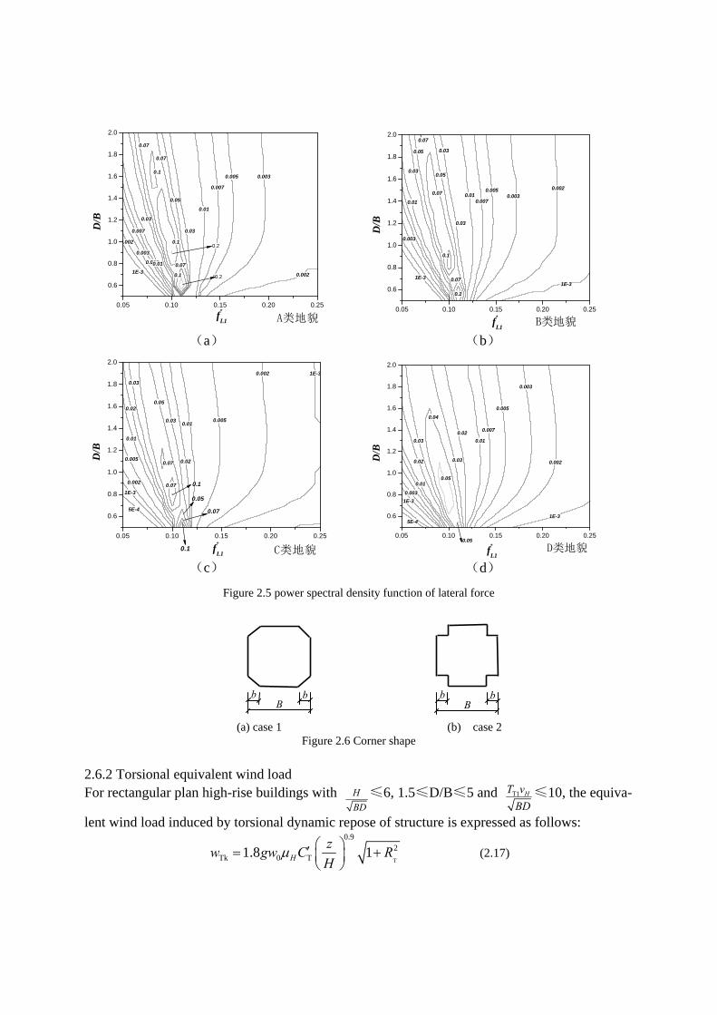
Where LC =lateral force coefficient; LR =resonant factor of cross-wind vibration; LFS =power
spectral density function of lateral force, given in Figure 2.5 (L1 L1
* / Hf f B v ); mC , smC = modi-
fication factor of force and spectrum for corner shape (Figure 2.6, Table2.4); RC =factor of
ground roughness (0.236, 0.211, 0.202 and 0.197 for A to D); a1 =aerodynamic damping ratio; *
L1T = reduced period.
1E-3
0.002
0.003
0.005
0.007
0.01
0.03
0.03
0.01
0.007
0.005 0.003
0.05
0.07
0.07
0.07
0.002
0.1
0.1
0.1
0.05 0.10 0.15 0.20 0.25
0.6
0.8
1.0
1.2
1.4
1.6
1.8
2.0
0.2
0.2
f*
L1
D/B
A类地貌
(a)
1E-3
0.003
0.01
0.03
0.05
0.05
0.03
0.03
0.010.007
0.0050.003
0.002
1E-30.07
0.07
0.07
0.1
0.1
0.05 0.10 0.15 0.20 0.25
0.6
0.8
1.0
1.2
1.4
1.6
1.8
2.0
B类地貌f*
L1
D/B
(b)
5E-4
1E-3
0.002
0.005
0.01
0.02
0.03
0.03
0.02
0.010.005
0.002 1E-3
0.05
0.07
0.07
0.05 0.10 0.15 0.20 0.25
0.6
0.8
1.0
1.2
1.4
1.6
1.8
2.0
0.07
0.1
0.05
C类地貌f*
L1
D/B
0.1
(c)
5E-4
1E-3
0.003
0.01
0.02
0.03
0.03
0.02
0.01
0.007
0.005
0.003
0.002
0.04
1E-3
0.05
0.05 0.10 0.15 0.20 0.25
0.6
0.8
1.0
1.2
1.4
1.6
1.8
2.0
D类地貌f*
L1
D/B
0.05
(d)
Figure 2.5 power spectral density function of lateral force
(a) case 1 (b) case 2
Figure 2.6 Corner shape 2.6.2 Torsional equivalent wind load For rectangular plan high-rise buildings with H
BD≤6, 1.5≤D/B≤5 and T1 HT v
BD≤10, the equiva-
lent wind load induced by torsional dynamic repose of structure is expressed as follows:
T
0.92
Tk 0 T1.8 1H
zw gw C R
H
(2.17)
b bB
b bB

Table 2.4 Values of coefficient smC
Reduced frequency (L1
*f ) case
Ground
roughness b/B
0.100 0.125 0.150 0.175 0.200 0.225 0.250
5% 0.183 0.905 1.2 1.2 1.2 1.2 1.1
10% 0.070 0.349 0.568 0.653 0.684 0.670 0.653 B
20% 0.106 0.902 0.953 0.819 0.743 0.667 0.626
5% 0.368 0.749 0.922 0.955 0.943 0.917 0.897
10% 0.256 0.504 0.659 0.706 0.713 0.697 0.686
1
D
20% 0.339 0.974 0.977 0.894 0.841 0.805 0.790
5% 0.106 0.595 0.980 1.0 1.0 1.0 1.0
10% 0.033 0.228 0.450 0.565 0.610 0.604 0.594 B
20% 0.042 0.842 0.563 0.451 0.421 0.400 0.400
5% 0.267 0.586 0.839 0.955 0.987 0.991 0.984
10% 0.091 0.261 0.452 0.567 0.613 0.633 0.628
2
D
20% 0.169 0.954 0.659 0.527 0.475 0.447 0.453
0.782T 0.0066 0.015( / )C D B (2.18)
TT T
14
FR K
(2.19)
0.12 2
T 2
( )
20
B D zK
r H
(2.20)
Where TC =torsional force coefficient; TR =resonant factor of torsional vibration;
LFS = power
spectral density function of torsion; TF = energy factor of torsional spectrum, given in Figure 2.7
( * T1T1
H
f BDf
v ).
0.001
0.001
0.00
2
0.002
0.005
0.005
0.01
0.01
0.02
0.02
0.05
0.1
0.1
0.1 5
0.15
0.15
0.2
0.2
0.2
0.3
0.3
0.3
0.4
0.4
0.5
0.55
0.1 0.2 0.3 0.4 0.5 0.6 0.7 0.8 0.9 11.5
2
2.5
3
3.5
4
4.5
5
Figure 2.7 energy factor of torsional spectrum

2.7 Combination of along-wind, cross-wind and torsional wind load
Along-wind, cross-wind and torsional wind load given as following should be combined accord-ing to Table 2.5.
Dk k1 k2( )F w w B (2.21)
Lk LkF w B (2.22)
2Tk TkT w B (2.23)
Table 2.5 Wind load combination
Load case Along-wind Cross-wind Torsional
1 DkF - -
2 0.6 DkF LkF -
3 - - TkT
3. CRITERIA AND GUIDELINE FOR WIND TUNNEL TESTING OF BRIDGES
With the origination and development of boundary layer wind tunnels by Jack E. Cermak and Alan G. Davenport in the 1960’s, the effects of wind for bridges and structures have been commonly determined through wind tunnel model studies, which include measurements of vari-ous types of information of interest, such as cladding loads, structural loads and pedestrian level wind speeds. In order to assist researchers and engineers who may become involved with the wind tunnel model testing, each country, area or institute may have their own appropriate criteria and guideline to specify wind tunnel testing with various models, which results in several guide-lines or manuals of practice in the world, for example, the ASCE Manual of Practice for Wind Tunnel Studies of Buildings and Structures in 1987 and 1999 [6], the Wind Tunnel Testing: A General Outline (University of Western Ontario) in 1991 and 2007 [7], the AIJ Guideline for Wind Tunnel Testing of Buildings in Japan in 1994 and 2009 [8], the Wind Tunnel Experiments for Honshu-Shikoku Bridges in Japan in 1980 [9], the Wind Resistant Design Guidelines for Highway Bridges in China in 1996 [10], the Wind Resistant Design Specification for Highway Bridges in China 2004 [11], and so on. While the first three guidelines or manuals of practice published mainly involve in buildings and structures, the next three certainly relate to bridges. These documents may have some underlying differences between one to another.
Under the globalization of the construction industry and the development of unified interna-tional codes and standards, it is believed that it is necessary to provide practical unified experi-mental methodology on the aerodynamics and aeroelastics of a wide range of bridges and bridge elements, such as decks, pylons, cables, hangers and so on. Thus Chinese wind engineering community, under the leadership of State Key Laboratory for Disaster Reduction in Civil Engi-neering and Tongji University, are working to provide a contribution towards a specific and agreed criteria and guideline of wind tunnel testing of bridges, in particular with long spans. In order to achieve this goal, following studies are being conducted:
(1) To study model law and similitude theory of wind tunnel testing of bridge aerodynamics and aeroelastics;
(2) To investigate testing procedures and experimental techniques of model studies in boundary layer wind tunnels;

(3) To assess the validity and consistency of interpreting or extrapolating methods for model testing results to the prediction of full-scale prototype behavior.
4. GUIDELINE FOR WIND TUNNEL TESTING OF BUILDING STRUCTURES
In the Chinese wind engineering community, currently there is no official guideline on the wind tunnel tests of building structures. Practically people often refer to ASCE Manual of Prac-tice for Wind Tunnel Studies of Buildings and Structures [6], the AIJ Guideline for Wind Tunnel Testing of Buildings in Japan [8] and others. China Academy of Building Research is taking the action in establishing a guideline for wind tunnel testing of building structures, which is esti-mated to function as a national code. All the wind engineering groups in China are invited into the technical committee, and the documental work is proceeded through intensive discussions.
One feature of this guideline is that it covers the numerical approach (CFD) for assessing the wind load on structures.
3 REFERENCES
1 Xinyang JIN, Jida Zhao, Development of design code for building structures in China, Structural Engineering In-ternational, SEI Volume 22, Number 2, (2012)195-201.
2 Xinyang JIN, Principles and main points for the revision of Load code for the design of building structures, Journal of building structures, Vol. 32 No.12, 2011, 29-35.
3 Yi Tang, Ming Gu, Xinyang Jin, Research on Wind-Induced Response of Structurally Asymmetric Tall Build-ings[J], JOURNAL OF TONGJI UNIVERSITY(NATURAL SCIENCE), 38(2), 2010
4 M. Gu, Y. Quan, Across-wind loads of typical tall buildings[J], Journal of Wind Engineering and Industrial Aerodynamics, 92(2004) 1147-1165.
5 QUAN Yong, GU Ming, Power Spectra of Across- wind Loads on Super High- rise Buildings[J], JOURNAL OF TONGJI UNIVERSITY(NATURAL SCIENCE), 30(5), 2002.
6 American Society of Civil Engineers, ASCE Materials and Reports on Engineering Practice No. 67, Wind Tun-nel Studies of Buildings and Structures, the first edition in 1987, the edition of 1999.
7 Boundary Layer Wind Tunnel Laboratory of University of Western Ontario, Wind Tunnel Testing: A General Outline, the first issue in 1991 and the latest issue in 2007.
8 Architectural Institute of Japan, Guideline for Wind Tunnel Testing of Buildings (in Japanese), the first edition in 1994, the second edition in 2008.
9 Honshu-Shikoku Bridge Bureau, Wind Tunnel Experiments for Honshu-Shikoku Bridge (in Japanese), 1980. 10 H.F. Xiang, et al., Wind Resistant Design Guidelines for Highway Bridges (in Chinese), People’s Communica-
tion Press, Beijing, China, 1996. 11 Ministry of Communications, Wind Resistant Design Specification for Highway Bridges (in Chinese), People’s
Communication Press, Beijing, China, 2004.