chesterton seal division iso 9001 certified · 2016-07-25 · method and the stoker spreader...
TRANSCRIPT
PowerIndustrySealGuide
SEAL DIVISIONCHESTERTON®ISO 9001 CERTIFIED
THE NEW STANDARD FOR RELIABILITY070482 REV.1

CONTENTS
Power Plant Combustion Process 1
Power Plant Steam Cycle 2
Typical PowerPlant Systems 3
Basic Nuclear Power Cycles 4
Nuclear Specific Systems 5

THE NEW STANDARD FOR RELIABILITY®
POWER INDUSTRY
Introduction
MECHANICAL SEALDIVISION

The majority of electricity we use is pro-duced by machines called turbogenerators,which are a means of converting mechanicalenergy into electrical energy. They consist of a turbine connected by a drive shaft to anelectrical generator. A high velocity fluid(water or steam) strikes the blades of theturbine, inducing rotation. This high speedturbine is interconnected to the armature of a generator. The copper windings on thearmature produce an electric current as theycut through a magnetic field. This currentflows through transmission lines from the power grid to complex distribution networksthat supply homes, offices and industries.
There are three basic sources of energy:water power, chemical energy (fossil fuel) and atomic energy.
HYDROELECTRIC POWER PLANTSWater power is the most direct but also the
most limited source of electrical energy. It is the most direct source because there is adirect transfer of mechanical energy from thesource to the turbine shaft. Water power is themost limited source of energy, due to the facthydroelectric plants can only be built ingeographical locations where adequate flow of water is available. The best sites are oftenfound at a considerable distance frompopulated areas requiring long distancetransmission lines. The amount of power thatcan be generated varies due to seasonal andannual fluctuations in water flow.
FOSSIL FUEL POWER PLANTSPower generation produced by chemical
energy (combustion processes) will be thefocus of this guide. Combustion is the rapidchemical reaction between oxygen and thecombustion elements of a fuel, resulting inthe production of heat. Combustion is
accomplished by mixing fuel and air atelevated temperatures. The air suppliesoxygen, which unites chemically with thecarbon, hydrogen, and sulfur elements in the fuel that when ignited produce heat. This heat source is used to produce steamfrom water, in the boiler, through radiant and convective energy. There are a widevariety of fuels utilized for combustion. They are explained in the following section.
NUCLEAR POWER PLANTSA nuclear generator produces steam and
therefore is a boiler. The furnace for burning conventional fossil fuel is replaced by areactor, which contains a core of nuclear fuel.The core contains Uranium fuel which, as aresult of splitting atoms and the subsequentfissioning process, heat is released to producesteam. Fissioning is a chain reaction. When aneutron strikes the nucleus of Uranium atom,the nucleus splits (fissions), releasing largeamounts of heat and several more neutrons.Atomic energy makes up 22% of the powergenerated in the United States.
COGENERATIONPrimarily, a power generating station which
utilizes a combined-cycle cogeneration processfor maximum efficiency. Electricity can beproduced through two or more distinctlydifferent thermodynamic cycles utilizing thesame fuel. Cogeneration plants provideadditional utilities other than electricity e.g.,heating steam to buildings and chill water for air conditioning purposes. Cogeneration is popular in geographical areas where thedemand for more than one utility is high i.e., large populated areas.
PowerProduction

THE NEW STANDARD FOR RELIABILITY®
POWER INDUSTRY
I. Power Plant Combustion Process1.Coal Fired2.Oil Fired3. Nuclear4. By-Product5. Refuse Oils
MECHANICAL SEALDIVISION

• COAL FIRED• OIL FIRED• REFUSE FUELS • BY-PRODUCT FUELS• NATURAL GAS
Coal Fired: Coal extracted from the ground from prehistoric decomposition can be utilized in combustion processes bytwo different methods i.e. the pulverizedmethod and the stoker spreader method. The coal is pulverized due to a low volatilecontent or to meet equipment specifications.A coal with a high volatile content generally is not pulverized and is burned on a spreaderstoker (traveling-grate). These types of stokersare readily adaptable for bark firing alone or in combination with coal. They are alsoutilized in the burning of municipal solidwaste in the form of refuse-derived fuel. Coal fired plants make-up 55% of the powergenerated in the United States. See followingschematic.
Oil Fired: The atomization of #6 fuel oil torefined fuel oil (#2) can be utilized to generatesteam from combustion. Atomization, theinjection of a fine mist of fuel oil into theboiler furnace, is achieved utilizing steam, air pressure or centrifugal force at the burnertip to aid combustion. Oil fired plants makeup 4% of the power generated in the United States.
Refuse Fuel: The incineration of municipalrefuse or solid waste to generate steam and electricity. Refuse derived fuel is burned on a spreader stoker, with natural gas or #2 fueloil as a secondary combustible in a waste-to-energy plant. Refuse plants make up 0.4% of power generated in the United States.
By-Product Fuels: Industrial processesfrequently produce materials which may beburned in industrial furnaces. The utilizationof these by-products not only reduces the cost of fuel, but frequently solves a disposalproblem. These by-product plants aregenerally small in power output for the reasonof concern for providing energy for their ownfacility purposes only. An example is wood ina saw mill or black liquor in a paper mill.
Natural Gas: As per Clean Air Act -Manufactured substitutes for natural gas may be produced from solid or liquid fuels.These gases are produced for special industrialapplication and for domestic use. Becausethey cost more than other fuels, they areseldom used under power boilers.
I. Power Plant Combustion Process

®
RECLAIMWATER
STEAM
RAW WATERINTAKE
BOTTOMASH
TODISPOSAL
BOILER
FLUE GASTREATMENT(SCRUBBER)
SYSTEM
COAL HANDLINGSYSTEM
COOLINGSYSTEM
TURBINE, GENERATOR,CONDENSATE SYSTEM
FLUEGAS
ASHWATER
ASHPOND
COALPULVERIZED
COAL
PYRITES
DRYFLYASH
TREATEDFLUEGAS
SLUDGE
COOLINGWATER
HEATEDWATER
REJECTHEAT
CONDENSATE
TODISPOSAL ASH
ASH HANDLINGSYSTEM
Coal Fired Plant
SCRUBBERWATER

THE NEW STANDARD FOR RELIABILITY®
POWER INDUSTRY
II. Power Plant Steam Cycle
MECHANICAL SEALDIVISION
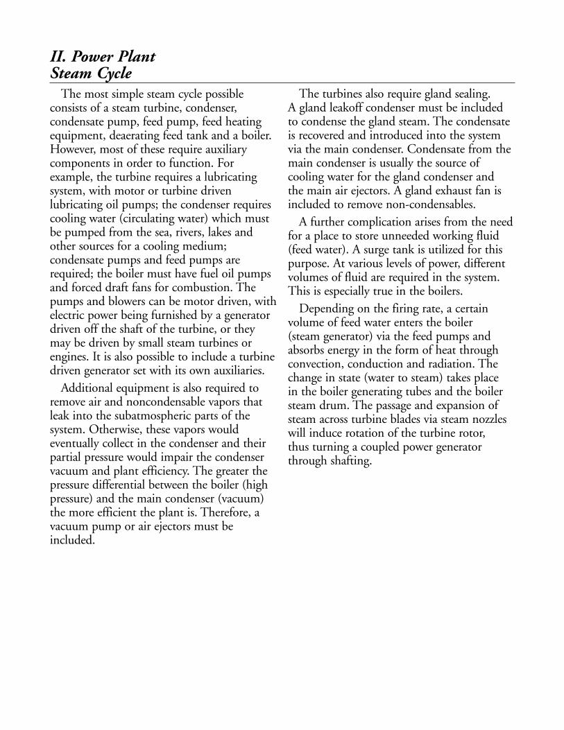
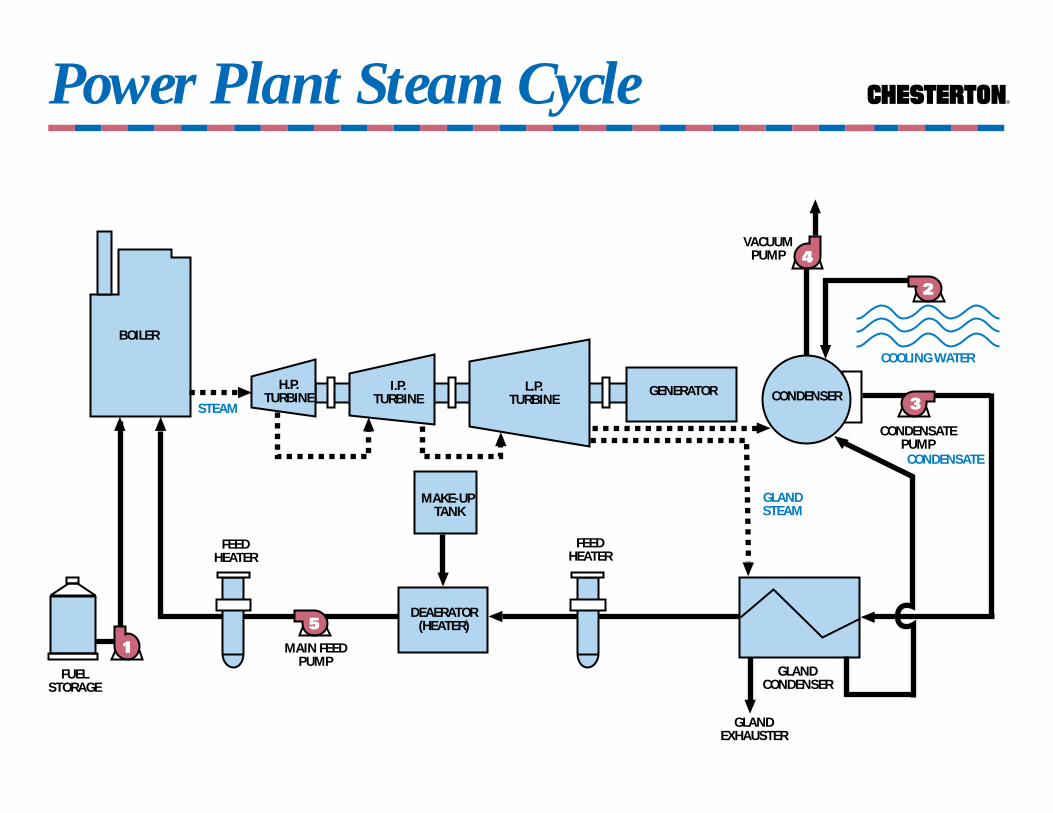
The most simple steam cycle possibleconsists of a steam turbine, condenser,condensate pump, feed pump, feed heatingequipment, deaerating feed tank and a boiler.However, most of these require auxiliarycomponents in order to function. Forexample, the turbine requires a lubricatingsystem, with motor or turbine drivenlubricating oil pumps; the condenser requirescooling water (circulating water) which mustbe pumped from the sea, rivers, lakes andother sources for a cooling medium;condensate pumps and feed pumps arerequired; the boiler must have fuel oil pumpsand forced draft fans for combustion. Thepumps and blowers can be motor driven, withelectric power being furnished by a generatordriven off the shaft of the turbine, or theymay be driven by small steam turbines orengines. It is also possible to include a turbinedriven generator set with its own auxiliaries.
Additional equipment is also required toremove air and noncondensable vapors thatleak into the subatmospheric parts of thesystem. Otherwise, these vapors wouldeventually collect in the condenser and theirpartial pressure would impair the condenservacuum and plant efficiency. The greater thepressure differential between the boiler (highpressure) and the main condenser (vacuum)the more efficient the plant is. Therefore, avacuum pump or air ejectors must beincluded.
The turbines also require gland sealing. A gland leakoff condenser must be includedto condense the gland steam. The condensateis recovered and introduced into the systemvia the main condenser. Condensate from themain condenser is usually the source ofcooling water for the gland condenser and the main air ejectors. A gland exhaust fan isincluded to remove non-condensables.
A further complication arises from the needfor a place to store unneeded working fluid(feed water). A surge tank is utilized for thispurpose. At various levels of power, different volumes of fluid are required in the system.This is especially true in the boilers.
Depending on the firing rate, a certainvolume of feed water enters the boiler (steam generator) via the feed pumps andabsorbs energy in the form of heat throughconvection, conduction and radiation. Thechange in state (water to steam) takes place in the boiler generating tubes and the boilersteam drum. The passage and expansion ofsteam across turbine blades via steam nozzleswill induce rotation of the turbine rotor, thus turning a coupled power generatorthrough shafting.
II. Power Plant Steam Cycle
Power Plant Steam Cycle ®
FUELSTORAGE
CONDENSATEPUMP
GLANDCONDENSER
5
MAKE-UP TANK
STEAMCONDENSER
COOLING WATER
3
1
VACUUMPUMP
CONDENSATE
DEAERATOR(HEATER)
2
L.P.TURBINE
BOILER
GLANDSTEAM
4
H.P.TURBINE
I.P.TURBINE
GENERATOR
MAIN FEEDPUMP
FEEDHEATER
FEEDHEATER
GLANDEXHAUSTER
THE NEW STANDARD FOR RELIABILITY®
POWER INDUSTRY
III. Typical Power Plant SystemsCondensate System/Vacuum SystemHeater DrainsMain Feed WaterFeed BoosterCirculating Water SystemScreen WashAnti-Fouling SystemFuel Oil SystemSulfur Dioxide Scrubber SystemsFly Ash SystemLubricating Oil SystemWater Demineralizer/Treatment SystemGenerator Hydrogen and Seal Oil System
MECHANICAL SEALDIVISION
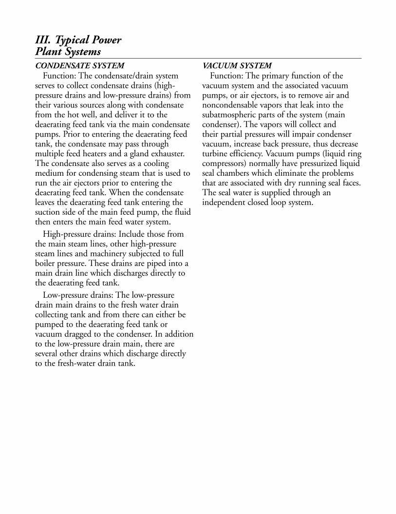
CONDENSATE SYSTEMFunction: The condensate/drain system
serves to collect condensate drains (high-pressure drains and low-pressure drains) fromtheir various sources along with condensatefrom the hot well, and deliver it to thedeaerating feed tank via the main condensatepumps. Prior to entering the deaerating feedtank, the condensate may pass throughmultiple feed heaters and a gland exhauster.The condensate also serves as a coolingmedium for condensing steam that is used torun the air ejectors prior to entering thedeaerating feed tank. When the condensateleaves the deaerating feed tank entering thesuction side of the main feed pump, the fluidthen enters the main feed water system.
High-pressure drains: Include those fromthe main steam lines, other high-pressuresteam lines and machinery subjected to fullboiler pressure. These drains are piped into amain drain line which discharges directly tothe deaerating feed tank.
Low-pressure drains: The low-pressuredrain main drains to the fresh water draincollecting tank and from there can either bepumped to the deaerating feed tank orvacuum dragged to the condenser. In additionto the low-pressure drain main, there areseveral other drains which discharge directlyto the fresh-water drain tank.
VACUUM SYSTEMFunction: The primary function of the
vacuum system and the associated vacuumpumps, or air ejectors, is to remove air andnoncondensable vapors that leak into thesubatmospheric parts of the system (maincondenser). The vapors will collect and their partial pressures will impair condenservacuum, increase back pressure, thus decreaseturbine efficiency. Vacuum pumps (liquid ringcompressors) normally have pressurized liquidseal chambers which eliminate the problemsthat are associated with dry running seal faces.The seal water is supplied through anindependent closed loop system.
III. Typical PowerPlant Systems

Condensate System ®
TO DRAIN
TO CONDENSER
CONDENSER
CONDENSATE
FROM HEATERDRAIN PUMPS
VACUUM
FEEDHEATER
NO. 2
2
HOTWELL
TO BOILERFEED PUMP
SUCTION
TO DRAIN
AIREJECTOR
CONDENSER
1
DRAINCOOLER
GLANDSTEAM
CONDENSER
FEEDHEATER
NO. 3
TO DRAIN
TO LP DRAIN
TO DRAIN
GLAND STEAM
HEATING STEAM HEATING STEAM
3
CONDENSATEPUMPS
CONDENSATE
CONDENSATE
DEAERATOR(HEATER)
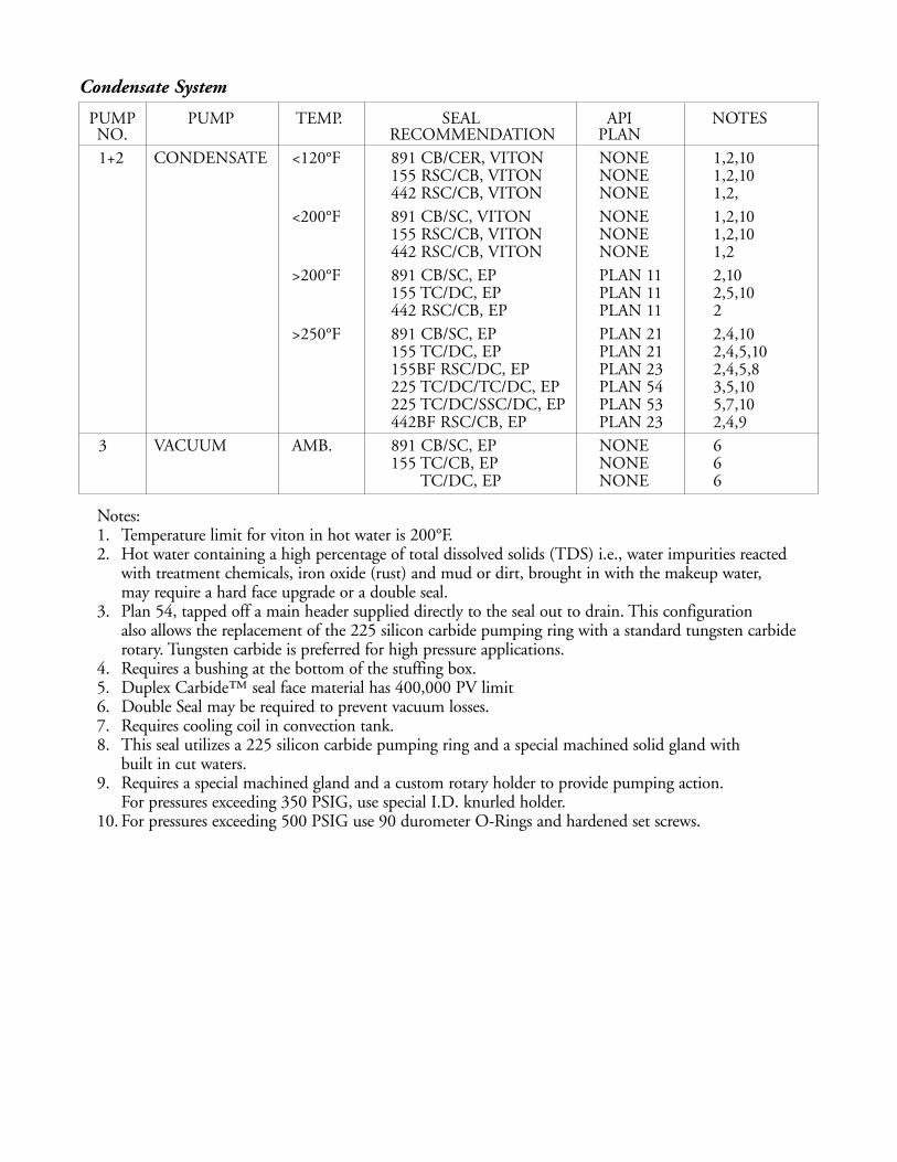
Condensate System
PUMP PUMP TEMP. SEAL API NOTESNO. RECOMMENDATION PLAN1+2 CONDENSATE <120°F 891 CB/CER, VITON NONE 1,2,10
155 RSC/CB, VITON NONE 1,2,10442 RSC/CB, VITON NONE 1,2,
<200°F 891 CB/SC, VITON NONE 1,2,10155 RSC/CB, VITON NONE 1,2,10442 RSC/CB, VITON NONE 1,2
>200°F 891 CB/SC, EP PLAN 11 2,10155 TC/DC, EP PLAN 11 2,5,10442 RSC/CB, EP PLAN 11 2
>250°F 891 CB/SC, EP PLAN 21 2,4,10155 TC/DC, EP PLAN 21 2,4,5,10155BF RSC/DC, EP PLAN 23 2,4,5,8225 TC/DC/TC/DC, EP PLAN 54 3,5,10225 TC/DC/SSC/DC, EP PLAN 53 5,7,10442BF RSC/CB, EP PLAN 23 2,4,9
3 VACUUM AMB. 891 CB/SC, EP NONE 6155 TC/CB, EP NONE 6
TC/DC, EP NONE 6
Notes:1. Temperature limit for viton in hot water is 200°F.2. Hot water containing a high percentage of total dissolved solids (TDS) i.e., water impurities reacted
with treatment chemicals, iron oxide (rust) and mud or dirt, brought in with the makeup water, may require a hard face upgrade or a double seal.
3. Plan 54, tapped off a main header supplied directly to the seal out to drain. This configuration also allows the replacement of the 225 silicon carbide pumping ring with a standard tungsten carbide rotary. Tungsten carbide is preferred for high pressure applications.
4. Requires a bushing at the bottom of the stuffing box.5. Duplex Carbide™ seal face material has 400,000 PV limit6. Double Seal may be required to prevent vacuum losses.7. Requires cooling coil in convection tank.8. This seal utilizes a 225 silicon carbide pumping ring and a special machined solid gland with
built in cut waters. 9. Requires a special machined gland and a custom rotary holder to provide pumping action.
For pressures exceeding 350 PSIG, use special I.D. knurled holder.10. For pressures exceeding 500 PSIG use 90 durometer O-Rings and hardened set screws.

Heater Drain System
PUMP PUMP TEMP. SEAL API NOTESNO. RECOMMENDATION PLAN
1+2 CONDENSATE <120°F 891 CB/CER, VITON NONE 1,2,9155 RSC/CB, VITON NONE 1,2,9442 RSC/CB, VITON NONE 1,2
<200°F 891 CB/SC, VITON NONE 1,2,9155 RSC/CB, VITON NONE 1,2,9442 RSC/CB, VITON NONE 1,2
>200°F 891 CB/SC, EP PLAN 11 2,5,9155 TC/DC, EP PLAN 11 2,5,9442 RSC/CB, EP PLAN 11 2
>250°F 891 CB/SC, EP PLAN 21 2,4,9155 TC/DC, EP PLAN 21 2,4,5,9155 RSC/DC, EP PLAN 23 2,4,5,6,7,9225 TC/DC/TC/DC, EP PLAN 54 3,5,9225 TC/DC/RSC/DC, EP PLAN 53 5,6,9442 RSC/CB, EP PLAN 23 2,4,8
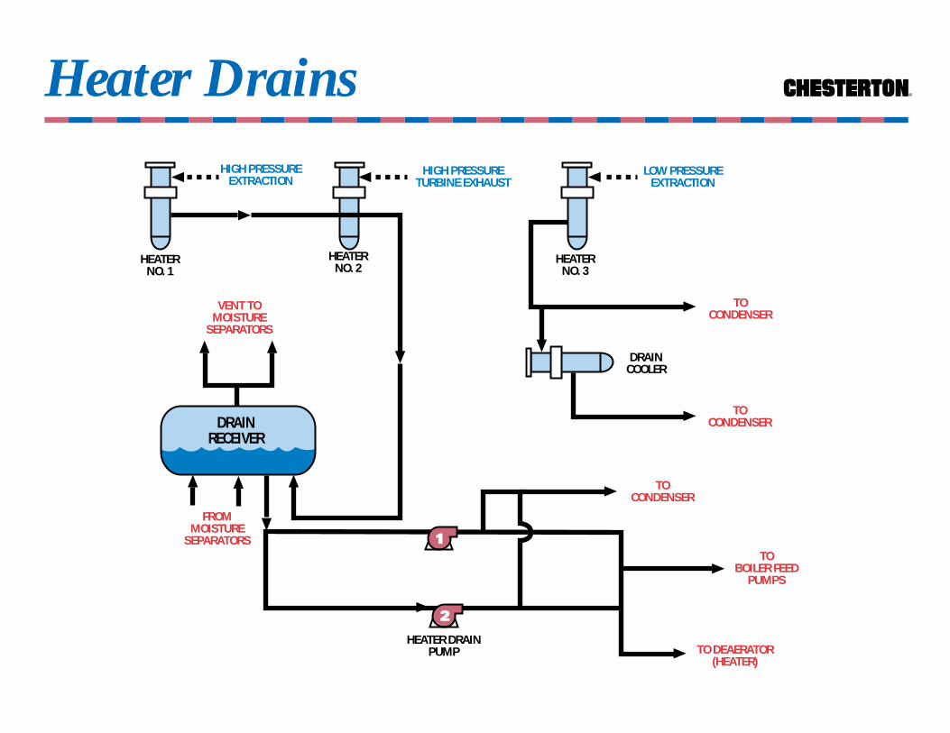
HEATER DRAIN SYSTEMFunction: The heater drain system is a
means for condensate recovery from the steam used on the shell side of feed heaters andmoisture separators. The condensate istypically re-introduced into the condensatesystem via three methods.
Methods:•Pumped into the system from the heater drain tank to the Main Feed Pump suction
•Vacuum dragged to the condenser•Gravity feed to fresh water drain collecting tanks
Notes:1. Temperature limit for viton in hot water is 200°F.2. Hot water containing a high percentage of total dissolved solids (TDS) i.e., water impurities reacted
with treatment chemicals, iron oxide (rust) and mud or dirt, brought in with the makeup water, may require a hard face upgrade or a double seal.
3. Plan 54, tapped off a main header supplied directly to the seal out to drain. This configuration also allows the replacement of the 225 silicon carbide pumping ring with a standard tungsten carbide rotary. Tungsten carbide is preferred for high pressure applications.
4. Requires a bushing at the bottom of the stuffing box. 5. Duplex Carbide™ seal face material has 400,000 PV limit6. Requires cooling coil in convection tank.7. This seal utilizes a 225 silicon carbide pumping ring and a special machined API gland with built
in cut waters. 8. Requires a special machined gland and a custom rotary holder to provide pumping action.
For pressures exceeding 350 PSIG, use special I.D. knurled holder.9. For pressures exceeding 500 PSIG use 90 durometer O-Rings and hardened set screws.
Heater Drains ®
TOBOILER FEED
PUMPS
HEATER DRAINPUMP
TOCONDENSER
HEATERNO. 1
2
FROMMOISTURE
SEPARATORS
HIGH PRESSURETURBINE EXHAUST
1
DRAINCOOLER
HEATERNO. 3
HIGH PRESSUREEXTRACTION
LOW PRESSUREEXTRACTION
VENT TOMOISTURE
SEPARATORS
DRAINRECEIVER
HEATERNO. 2
TOCONDENSER
TOCONDENSER
TO DEAERATOR(HEATER)

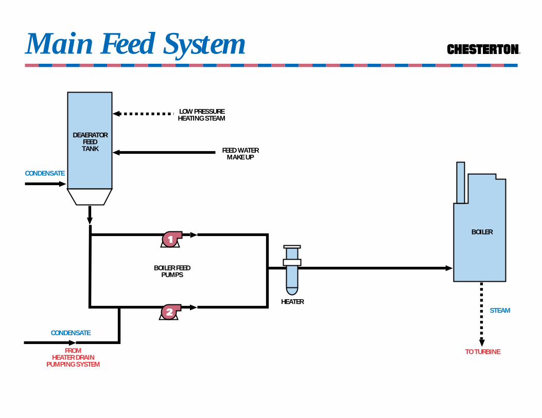
MAIN FEED SYSTEMFunction: Provides a continuous supply of
treated, pressurized, heated and deaeratedwater to the boilers. The water is transformedto steam in the steam generator by theabsorption of energy in the form of heat byconvection, conduction and radiation. Thefeed pumps take suction from the maincondensate system via the deaerating feedtank or feed booster pumps. At least twopumps must be provided to conform toregulatory body requirements. Boiler feedwater comprises condensate from the mainand auxiliary systems, condensed heatingsteam, and miscellaneous fresh water drains,that has passed through numerous feedheaters. Feed water will always contain a
percentage of total dissolved solids (TDS)which include scale forming impuritiesreacted with treatment chemicals, iron oxide(rust) and dirt or mud.
FEED BOOSTER SYSTEMFunction: Feed booster pumps provide feed
water to the main feed pumps with adeaerating heater type feed system, wherespace restrictions prevent locating thedeaerating feed heater at a sufficient staticelevation above the boiler feed pump suction.The point being, to provide the required netpositive suction head for the main feedpumps. Feed booster pumps are in manyrespects similar to condensate pumps.
Feed Water
PUMP PUMP TEMP. SEAL API NOTESNO. RECOMMENDATION PLAN1+2 FEED WATER >350°F 155BF RSC/DC, EP PLAN 23 1,2,3,4,5,6
155 TC/DC, EP PLAN 21 1,2,3,5225 TC/DC/TC/DC,EP PLAN 54 2,3,5891 CB/SC, EP PLAN 21 1,3,5
Notes:1. Requires bushing at bottom of stuffing box.2. Duplex Carbide™ seal face material has 400,000 PV limit.3. For pressures exceeding 500 PSIG use 90 durometer O-Rings and hardened set screws.4. This seal utilizes a 225 silicon carbide pumping ring and a special machined solid gland with
built in cut waters.5. Temperatures <350°F - see condensate system.6. Consult Application Engineering.
Main Feed System ®
HEATER
BOILER
TO TURBINE
DEAERATORFEEDTANK
CONDENSATE
BOILER FEEDPUMPS
FEED WATERMAKE UP
LOW PRESSUREHEATING STEAM
2
1
STEAM
CONDENSATE
FROMHEATER DRAIN
PUMPING SYSTEM
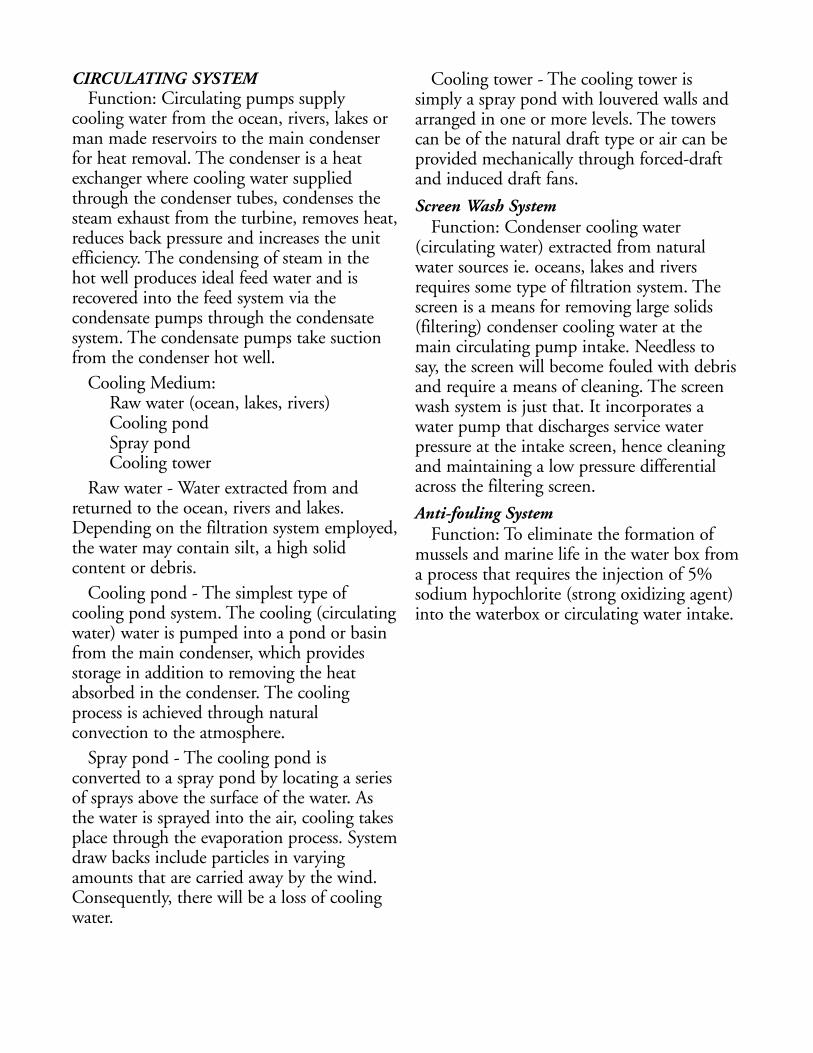
CIRCULATING SYSTEM Function: Circulating pumps supply
cooling water from the ocean, rivers, lakes orman made reservoirs to the main condenserfor heat removal. The condenser is a heatexchanger where cooling water suppliedthrough the condenser tubes, condenses thesteam exhaust from the turbine, removes heat,reduces back pressure and increases the unitefficiency. The condensing of steam in the hot well produces ideal feed water and isrecovered into the feed system via thecondensate pumps through the condensatesystem. The condensate pumps take suctionfrom the condenser hot well.
Cooling Medium:Raw water (ocean, lakes, rivers)Cooling pondSpray pond Cooling tower
Raw water - Water extracted from andreturned to the ocean, rivers and lakes.Depending on the filtration system employed,the water may contain silt, a high solidcontent or debris.
Cooling pond - The simplest type ofcooling pond system. The cooling (circulatingwater) water is pumped into a pond or basinfrom the main condenser, which providesstorage in addition to removing the heatabsorbed in the condenser. The coolingprocess is achieved through naturalconvection to the atmosphere.
Spray pond - The cooling pond isconverted to a spray pond by locating a seriesof sprays above the surface of the water. Asthe water is sprayed into the air, cooling takesplace through the evaporation process. Systemdraw backs include particles in varyingamounts that are carried away by the wind.Consequently, there will be a loss of coolingwater.
Cooling tower - The cooling tower issimply a spray pond with louvered walls andarranged in one or more levels. The towerscan be of the natural draft type or air can beprovided mechanically through forced-draftand induced draft fans.
Screen Wash SystemFunction: Condenser cooling water
(circulating water) extracted from naturalwater sources ie. oceans, lakes and riversrequires some type of filtration system. Thescreen is a means for removing large solids(filtering) condenser cooling water at themain circulating pump intake. Needless tosay, the screen will become fouled with debrisand require a means of cleaning. The screenwash system is just that. It incorporates awater pump that discharges service waterpressure at the intake screen, hence cleaningand maintaining a low pressure differentialacross the filtering screen.
Anti-fouling SystemFunction: To eliminate the formation of
mussels and marine life in the water box froma process that requires the injection of 5%sodium hypochlorite (strong oxidizing agent)into the waterbox or circulating water intake.
Circulating Water System ®
SCREEN WASHPUMP
3
SODIUMHYPOCHLORITE
PUMP
RAW WATER
1
TRAVELLINGSCREEN
CONDENSER
CIRCULATINGWATERPUMP
RAW WATERRETURN
STEAM
FROMTURBINE
2
CONDENSATE
TOCONDENSATE
SYSTEM
OUTLETWATER
BOX
INLETWATER
BOX
SODIUMHYPOCHLORITE
TANK
Circulating System
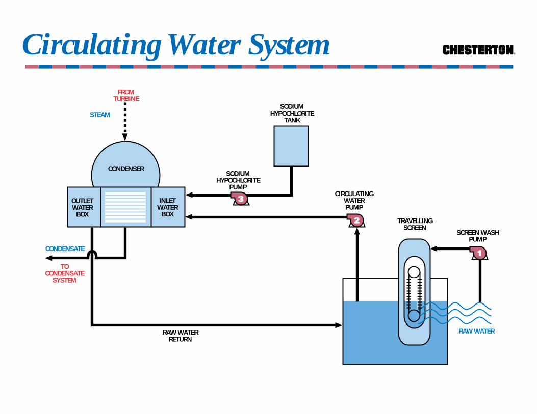
PUMP PUMP TEMP. SEAL API NOTESNO. RECOMMENDATION PLAN
1 SCREEN WASH AMB. 155 TC/DC, EP NONE 2,5891 CB/CER, EP NONE 2,5442 CER/CB, EP NONE 2,5
2 CIRCULATING AMB. 155 TC/DC, EP NONE 2,5,6442 CER/CB, EP NONE 2,5,6891 CB/CER, EP NONE 2,5,6
3 5% SODIUM AMB. 155 SC/DC, EP NONE 1,3HYPOCHLORITE 891 CB/CER, EP NONE 1,3
155C SC/CB, EP PLAN 62 1,3,4123 SC/CB, EP PLAN 62 1,3,4
Notes:1. Alloy-20 or HASTELLOY-C metallurgy required.2. Hard face combination recommended with high silt concentrations.3. Tungsten carbide not compatible.4. Use if crystallization is a problem.5. Do not use Viton if pumps come in contact with salt water6. Vertical applications should be vented with a suction recirculation line (API Plan #13).
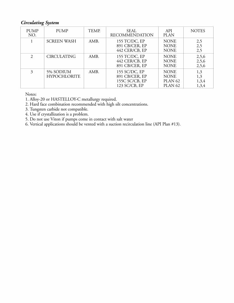
Fuel Oil System
PUMP PUMP TEMP. SEAL API NOTESNO. RECOMMENDATION PLAN1+2 SERVICE <180°F 155 SC/TC, VITON PLAN 11 3
891 TC/SC, VITON PLAN 11 3>180°F 155A SC/TC, VITON PLAN 11,62 1,3
123 TC/SC, VITON PLAN 11,62 1,3,891 TC/SC, VITON PLAN 11,62 1,3,4
>250°F 155 SC/TC, VITON PLAN 21 2891 TC/SC, VITON PLAN 21 2
3 TRANSFER <120°F 155 SC/TC, VITON NONE891 TC/SC, VITON NONE
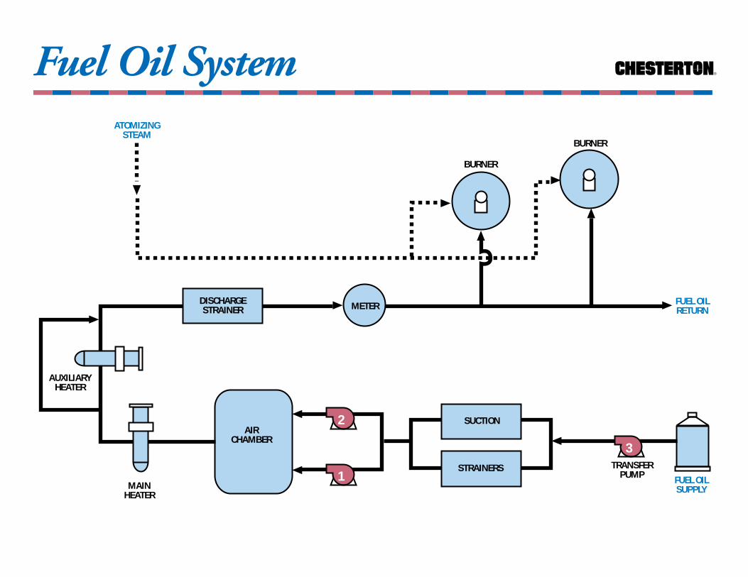
FUEL OIL SYSTEMFunction: Provide heated fuel oil for
combustion to the steam generator (boiler),during regular plant operation, cold start-upsor supplementary fuel conditions. Transferpumps and piping are provided for thetransfer of fuel oil to and from storage tanks.Fuel oil designation ranges from lightdomestic (#2) to heavy industrial (#6). In the typical power plant, fuel oil temperaturecan vary from 120°F in the storage tanks to180-260°F at the burners (heater discharge).
FuelsResidual Fuels - These are the fuels which
remain after the refining process. Residual fuelis usually free from moisture or sedimentexcept for that which is introduced byhandling and in transit from refinery to thepower plant.
Distillate Oils (#2 Fuel Oil) - The lightgrade of fuel oil obtained by fractionaldistillation and are of the consistency ofkerosene, diesel, and lubrication oils. Thesefuels typically are clean and free of sediment.
Unrefined Oils (#6 Fuel Oils) - This fuel islow in quality, thus making it ideal for usepower boilers. Bunker-C fuel oil typicallycontains sediment and abrasive materials.
Blended Oils - These are mixtures of two ofthe above, in proportions to meet desired specifications.
Notes:1. Plan 62 prevents coking at the seal faces.2. Plan 21 requires a bushing at bottom of the box.3. Plan 11 maintains fluid circulation through the stuffing box.4. A Plan 62 would require a special machined API gland for non-seal only pumps.
®
FUEL OILSUPPLY
AUXILIARYHEATER
ATOMIZINGSTEAM
MAINHEATER
FUEL OILRETURN
STRAINERS
2
1
AIRCHAMBER
BURNER
BURNER
SUCTION
DISCHARGESTRAINER
Fuel Oil System
METER
TRANSFERPUMP
3
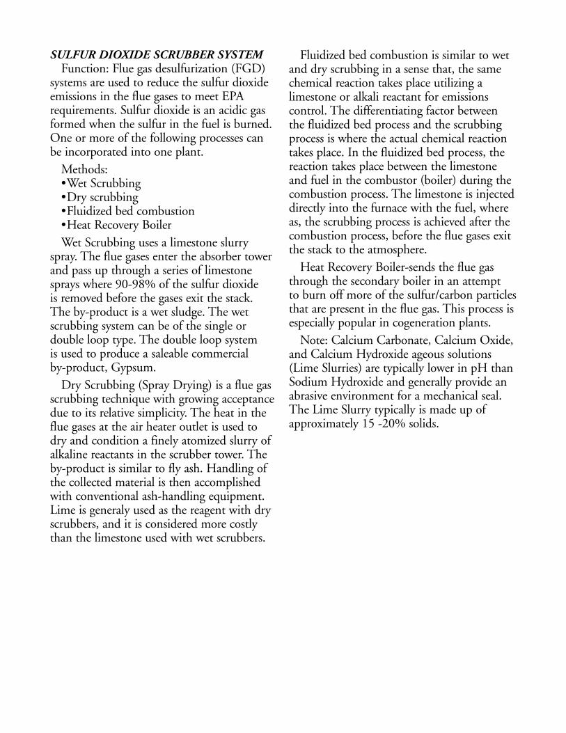
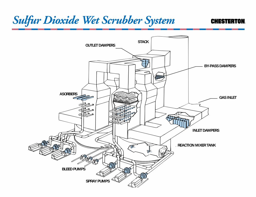
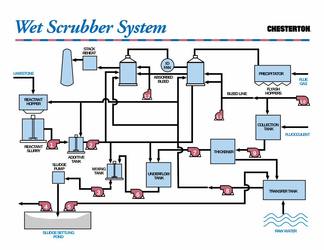
SULFUR DIOXIDE SCRUBBER SYSTEMFunction: Flue gas desulfurization (FGD)
systems are used to reduce the sulfur dioxideemissions in the flue gases to meet EPArequirements. Sulfur dioxide is an acidic gasformed when the sulfur in the fuel is burned.One or more of the following processes canbe incorporated into one plant.
Methods: •Wet Scrubbing•Dry scrubbing•Fluidized bed combustion•Heat Recovery BoilerWet Scrubbing uses a limestone slurry
spray. The flue gases enter the absorber towerand pass up through a series of limestonesprays where 90-98% of the sulfur dioxide is removed before the gases exit the stack. The by-product is a wet sludge. The wetscrubbing system can be of the single ordouble loop type. The double loop system is used to produce a saleable commercial by-product, Gypsum.
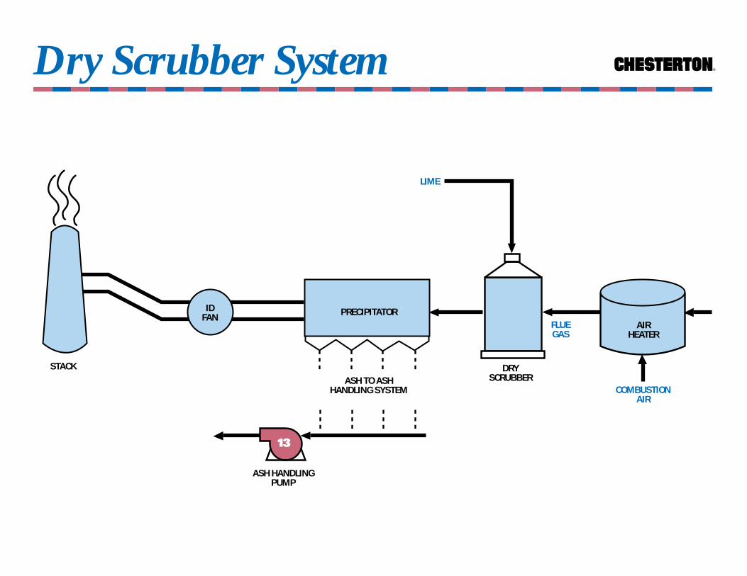
Dry Scrubbing (Spray Drying) is a flue gasscrubbing technique with growing acceptancedue to its relative simplicity. The heat in theflue gases at the air heater outlet is used to dry and condition a finely atomized slurry ofalkaline reactants in the scrubber tower. Theby-product is similar to fly ash. Handling ofthe collected material is then accomplishedwith conventional ash-handling equipment.Lime is generaly used as the reagent with dryscrubbers, and it is considered more costlythan the limestone used with wet scrubbers.
Fluidized bed combustion is similar to wetand dry scrubbing in a sense that, the samechemical reaction takes place utilizing alimestone or alkali reactant for emissionscontrol. The differentiating factor between the fluidized bed process and the scrubbingprocess is where the actual chemical reactiontakes place. In the fluidized bed process, thereaction takes place between the limestoneand fuel in the combustor (boiler) during thecombustion process. The limestone is injecteddirectly into the furnace with the fuel, whereas, the scrubbing process is achieved after thecombustion process, before the flue gases exitthe stack to the atmosphere.
Heat Recovery Boiler-sends the flue gasthrough the secondary boiler in an attempt to burn off more of the sulfur/carbon particlesthat are present in the flue gas. This process isespecially popular in cogeneration plants.
Note: Calcium Carbonate, Calcium Oxide,and Calcium Hydroxide ageous solutions (Lime Slurries) are typically lower in pH thanSodium Hydroxide and generally provide anabrasive environment for a mechanical seal.The Lime Slurry typically is made up ofapproximately 15 -20% solids.
®
STACK
Sulfur Dioxide Wet Scrubber System
OUTLET DAMPERS
ASORBERS
BLEED PUMPS
SPRAY PUMPS
REACTION MIXER TANK
GAS INLET
BY-PASS DAMPERS
INLET DAMPERS
®
ABSORBEDBLEED FLUE
GAS
RAW WATER
FLYASHHOPPERS
10
PRECIPITATOR
TRANSFER TANK
2
5
REACTANTHOPPER
REACTANTSLURRY
ADDITIVETANK
MIXINGTANK
12
SLUDGE SETTLINGPOND
STACKREHEAT
THICKENER
UNDERFLOWTANK
COLLECTION TANK
FLUOCCULENT
8
IDFAN
SLUDGEPUMP
BLEED LINE
11
3
1
Wet Scrubber System
97
6
4
LIMESTONE
®
DRYSCRUBBER
IDFAN
Dry Scrubber System
AIRHEATER
PRECIPITATOR
ASH HANDLINGPUMP
FLUEGAS
LIME
ASH TO ASHHANDLING SYSTEM
13
COMBUSTIONAIR
STACK

Scrubber System
PUMP PUMP TEMP. SEAL API NOTESNO. RECOMMENDATION PLAN
1 REACTANT AMB. 155 TC/TC, VITON PLAN 32 2,3SLURRY 156 TC/TC, VITON NONE 3
225 SSC/TC/SSC/CB,VITON PLAN 53 1,32 ADDITIVE AMB. 155 TC/TC,VITON PLAN 32 2,3
SLURRY 156 TC/TC,VITON NONE 320% SOLIDS 225 SSC/TC/SSC/CB,VITON PLAN 53 1,3
3 BOOSTER AMB. 155 SSC/TC,VITON PLAN 32 2,3 (SPENT SLURRY) 156 TC/TC,VITON NONE 3
225 SSC/TC/SSC/CB,VITON PLAN 53 1,34 SETTLING POND AMB. 155 SSC/TC,VITON PLAN 32 2,3,4
DISCHARGE 156 TC/TC,VITON NONE 35 DECANT AMB. 155 SSC/TC,VITON PLAN 32 2,3,4
WATER 156 TC/TC,VITON NONE 3225 SSC/TC/SSC/CB,VITON PLAN 53 1,3
6 UNDERFLOW AMB. 155 TC/TC,VITON PLAN 32 2,3156 TC/TC,VITON NONE 3225 TC/TC/SSC/CB,VITON PLAN 53 1,2,3
7 THICKENER AMB. 155 TC/TC,VITON PLAN 32 2,3156 TC/TC,VITON NONE 3225 TC/TC/SSC/CB,VITON PLAN 53 1,2,3
8 TRANSFER AMB. 155 SSC/TC,VITON PLAN 32 2,3156 TC/TC,VITON NONE 3225 TC/TC/SSC/CB PLAN 53 1,3
9 TRANSFER AMB. 155 SSC/TC,VITON PLAN 32 2,3156 TC/TC,VITON NONE 3225 TC/TC/SSC/CB PLAN 53 1,3
10 BLEED AMB. 155 SSC/TC,VITON PLAN 32 2,3,4156 TC/TC,VITON NONE 3225 SSC/TC/SSC/CB,VITON PLAN 53 1,3
11 SCRUBBER AMB. 155 SSC/TC,VITON PLAN 32 2,3RECYCLE 156 TC/TC,VITON NONE 314% SOLIDS 225 SSC/TC/SSC/CB,VITON PLAN 53 1,3
12 ABSORBER AMB. 155 SSC/TC,VITON PLAN 32 2,3RECYCLE 156 TC/TC,VITON NONE 314% SOLIDS 225 SSC/TC/SSC/CB PLAN 53 1,3
13 ASH PUMP AMB. 442 RSC/CB, EP PLAN 32 4442 RSC/RSC, EP PLAN 13156 RSC/TC, EP PLAN 13
Notes:1. Plan 54 is acceptable provided the water is clean and free of solids. With forced circulation the
outboard silicon carbide pumping ring can be replaced with a solid tungsten carbide seal face.2. If a Plan 32 cannot be implemented TC/TC seal faces are recommended.3. TC/TC seal faces are limited to 1750 RPM unless Applications Engineering is consulted for PV.4. A carbon stationary seal face may be used provided a Plan 32 is implemented and considered reliable.

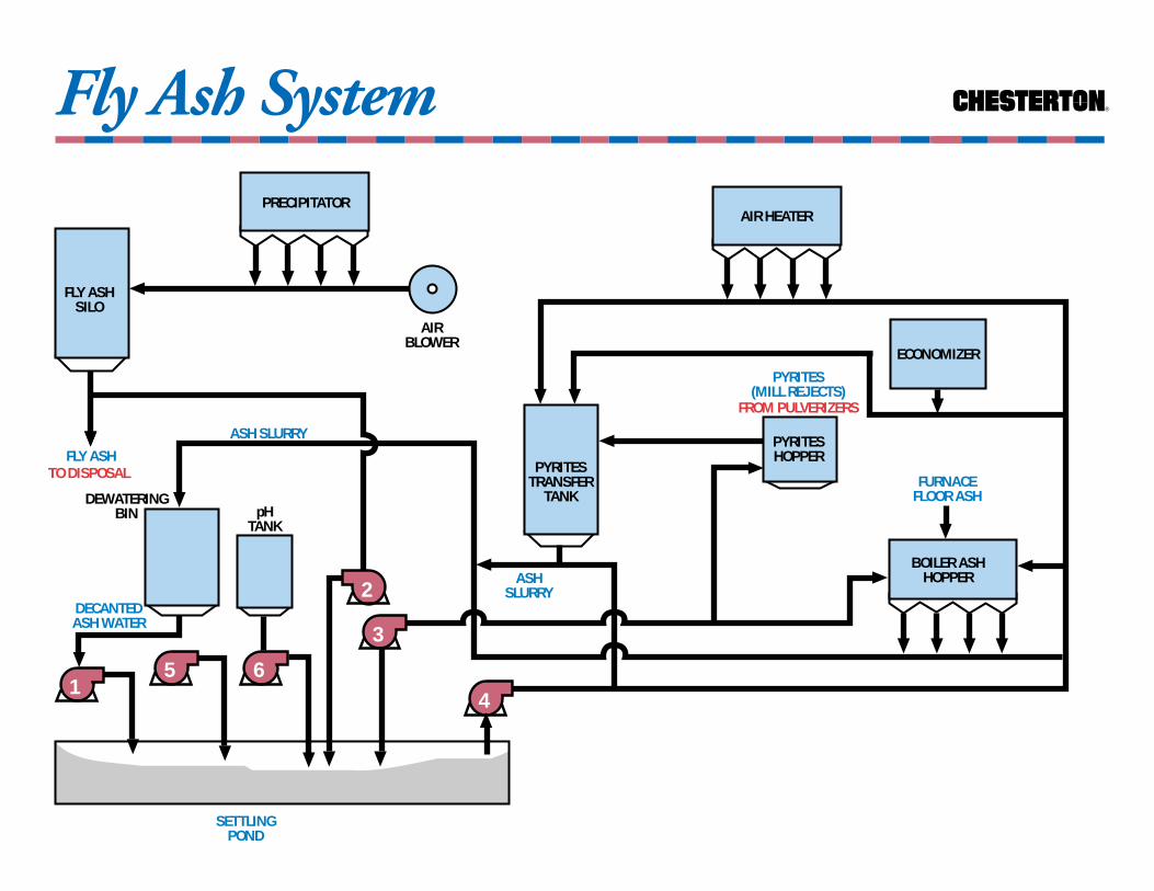
FLY ASH SYSTEMFunction: Remove products of combustion
from the furnace internals, flue gases and millrejects from pulverizers. Ash can be removedfrom the furnace in either a solid or liquidform. When burning pulverized coal, slag can be somewhat troublesome to removefrom boiler furnaces especially when burninglow-fusion-ash coal, due to its ability toharden on brickwork and waterwall tubes.Low fusion ash will be maintained in themolten liquid form due to high furnacetemperatures.
Furnaces can be designed to burn coal ofany fusion range. If the ash is removed in adry state, the unit is referred to as a drybottom furnace. Or for low fusion ash coal,the unit may be designed to remove the ash in liquid form; the unit is then called a wetbottom furnace. The liquid ash can beremoved on a continuous basis. Here themolten ash collects on the furnace floor, ismade to flow over a weir located in the floorof the furnace, and drops into a bath of waterbelow. Or the molten ash may be permittedto remain and collect on the furnace floor tobe tapped off at intervals. When the moltenash contacts the water; the chilling effectcauses the ash to form into fine granularparticles for ease of disposal. The ash/water is pumped from the boiler ash hopper anddischarged directly to a settling pond via the dewatering bin. Here after the ash settles outfrom the water, another set of pumps are provided to remove the water (recycle water)and return it to the plant for re-use.
Electrostatic precipitators are commonlyused for the collection of fly ash in flue gases.In an electrostatic precipitator ash-laden fluegas is distributed uniformly between rows ofdischarge electrodes and grounded collectingplates. A high voltage dc current is applied to the electrodes which causes the fly ash tobecome ionized and then to be attracted tothe grounded collecting plate. The collectedfly ash is periodically removed from the platesby a rapping system which generatesvibrations and causes the collected ash to fall into the hoppers. The ash falls from thehopper into the sluce system, a closed loop ofrunning water. The water/ash mixture is thendischarged to a settling pond to precipitatethe ash particles. The water is then extractedfrom the pond via return pumps andrecirculated.
With a pulverizer system, each boiler isequipped with one or more pulverizing millsthrough which coal passes on its way to theburners. After the pulverizing process a streamof primary air is supplied to carry the finecoal particles into the burner element. Thecoal is then discharged into the furnace forcombustion. The mill rejects (pyrites); whichcould damage mill elements; resist the upwardthrust of air and collect in a hopper at themill base. The pyrites are then periodicallyremoved to the fly ash silo for disposal orrecycle.
®
FLY ASH
2
SETTLINGPOND
ECONOMIZER
FROM PULVERIZERS
AIRBLOWER
1
FLY ASHSILO
4
PYRITESTRANSFER
TANK
BOILER ASHHOPPER
DEWATERINGBIN
DECANTEDASH WATER
5 6
ASH SLURRY
3
PYRITESHOPPER
ASHSLURRY
Fly Ash System
TO DISPOSAL
pHTANK
PYRITES(MILL REJECTS)
PRECIPITATORAIR HEATER
FURNACEFLOOR ASH

Fly Ash System
PUMP PUMP TEMP. SEAL API NOTESNO. RECOMMENDATION PLAN1 DECANTERED AMB. 155 RSC/TC, VITON PLAN 32 1
ASH WATER 156 TC/DC, VITON NONE225 TC/DC/SSC/CB, VITON PLAN 53 2,3442 RSC/CB, VITON PLAN 32 5
2 FLY ASH AMB. 155 RSC/TC, VITON PLAN 32 1UNLOADER 156 TC/DC, VITON NONE
225 TC/TC/SSC/CB, VITON PLAN 53 2,3,6442 RSC/CB, VITON PLAN 32 5
3 LOW PRESSURE AMB. 155 RSC/TC, VITON PLAN 32 1ASH WATER 156 TC/DC, VITON NONE
225 TC/DC/SSC/CB,VITON PLAN 53 2,3442 RSC/CB, VITON PLAN 32 5
4 HIGH PRESSURE AMB. 155 RSC/TC, VITON PLAN 32 1ASH WATER 225 TC/TC/SSC/CB, VITON PLAN 53 2,3,6
442 RSC/CB, VITON PLAN 32 55 ASH POND AMB. 155 RSC/TC, VITON PLAN 32 1
BLOWDOWN 156 TC/DC, VITON NONE225 TC/DC/SSC/CB, VITON PLAN 53 2,3442 RSC/CB, VITON PLAN 32 5
6 PH ADJUST. AMB. 155 SSC/TC, EP PLAN 32 1,4(CAUSTIC) 891 TC/SSC, EP PLAN 32 4
225 SSC/TC/SSC/CB, EP PLAN 53 2,3,4
Notes:1. If a Plan 32 cannot be implemented, TC/TC seal faces are recommended. Consult Applications
Engineering for PV.2. Plan 54 is acceptable provided the water is clean and free from solids.3. A Plan 54 allows the silicon carbide pumping ring to be replaced with a solid tungsten carbide seal face.4. RSC, DC seal faces are limited to concentrations < 5% in sodium hydroxide.5. If a Plan 32 cannot be implemented use RSC/RSC seal faces.6. TC/TC seal faces are limited to 1750 RPM unless Applications Engineering is consulted for PV.
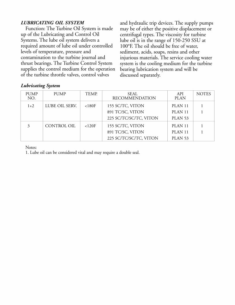
Lubricating System
PUMP PUMP TEMP. SEAL API NOTESNO. RECOMMENDATION PLAN
1+2 LUBE OIL SERV. <180F 155 SC/TC, VITON PLAN 11 1891 TC/SC, VITON PLAN 11 1225 SC/TC/SC/TC, VITON PLAN 53
3 CONTROL OIL <120F 155 SC/TC, VITON PLAN 11 1891 TC/SC, VITON PLAN 11 1225 SC/TC/SC/TC, VITON PLAN 53
Notes:1. Lube oil can be considered vital and may require a double seal.
LUBRICATING OIL SYSTEMFunction: The Turbine Oil System is made
up of the Lubricating and Control OilSystems. The lube oil system delivers arequired amount of lube oil under controlledlevels of temperature, pressure andcontamination to the turbine journal andthrust bearings. The Turbine Control Systemsupplies the control medium for the operationof the turbine throttle valves, control valves
and hydraulic trip devices. The supply pumpsmay be of either the positive displacement orcentrifugal types. The viscosity for turbinelube oil is in the range of 150-250 SSU at100°F. The oil should be free of water,sediment, acids, soaps, resins and otherinjurious materials. The service cooling watersystem is the cooling medium for the turbinebearing lubrication system and will bediscussed separately.
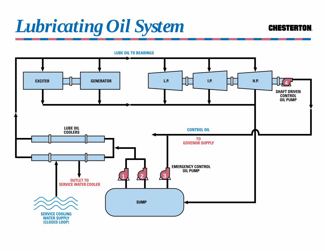
Lubricating Oil System ®
4
LUBE OILCOOLERS
TOGOVENOR SUPPLY
EXCITER GENERATOR
LUBE OIL TO BEARINGS
SERVICE COOLINGWATER SUPPLY(CLOSED LOOP)
OUTLET TOSERVICE WATER COOLER
EMERGENCY CONTROLOIL PUMP
SUMP
SHAFT DRIVENCONTROLOIL PUMP
L.P. I.P. H.P.
321
CONTROL OIL

WHY CHEMICAL TREATMENT?1.Prevent corrosion (oxygen removal)2.Prevent scale and sludge formation3.Prevent carry-over4.Prevent foaming5.Prevent priming6.Prevent caustic embrittlementCorrosion: Is a result of low alkaline boiler
feed water, the presence of free oxygen, orboth. The boiler metal is converted into redor black powder (iron oxide) which is readilywashed away by the water. The metalthickness is reduced and stress is increasedand concentrated.
Carry-Over: Is a continual discharge ofwater impurities with steam. These impuritiesmay be in the form of moisture whichcontain dissolved solids or of solids fromwhich the moisture has been removed. Carry-over is an objectable situation whichcan leave deposits on the turbine blades.
Foaming: Is a layer of foam on the watersurface in the boiler steam drum. Oil andother impurities which may enter thecondensate in an industrial plant will gatherand cause this condition. Extreme foamingwill cause carry-over with the steam, into themain steam line, entering the steam turbinecausing damage to the turbine blades.
Priming: Is a condition in which slugs ofwater are suddenly discharged with the steam.Primarily caused by impurities, boiler designand capacity at which the boiler is operated.
Caustic Embrittlement: Is a weakening ofboiler steel as the result of inner crystallinecracks. High alkaline water will cause this.
Water treatment includes such processes as deaerators for the removal of oxygen, watersofteners, demineralizers, chemical additivesand boiler blowdown. Frequent boilerblowdowns or continuous blows are a goodindication of the dissolved solids contentwithin the boiler feed water. Satisfactoryturbine operation requires steam to havedissolved solids not in excess of 0.1 ppm.Boiler water must be analyzed to determineits composition and the conditioningrequired.
Water Treatment System
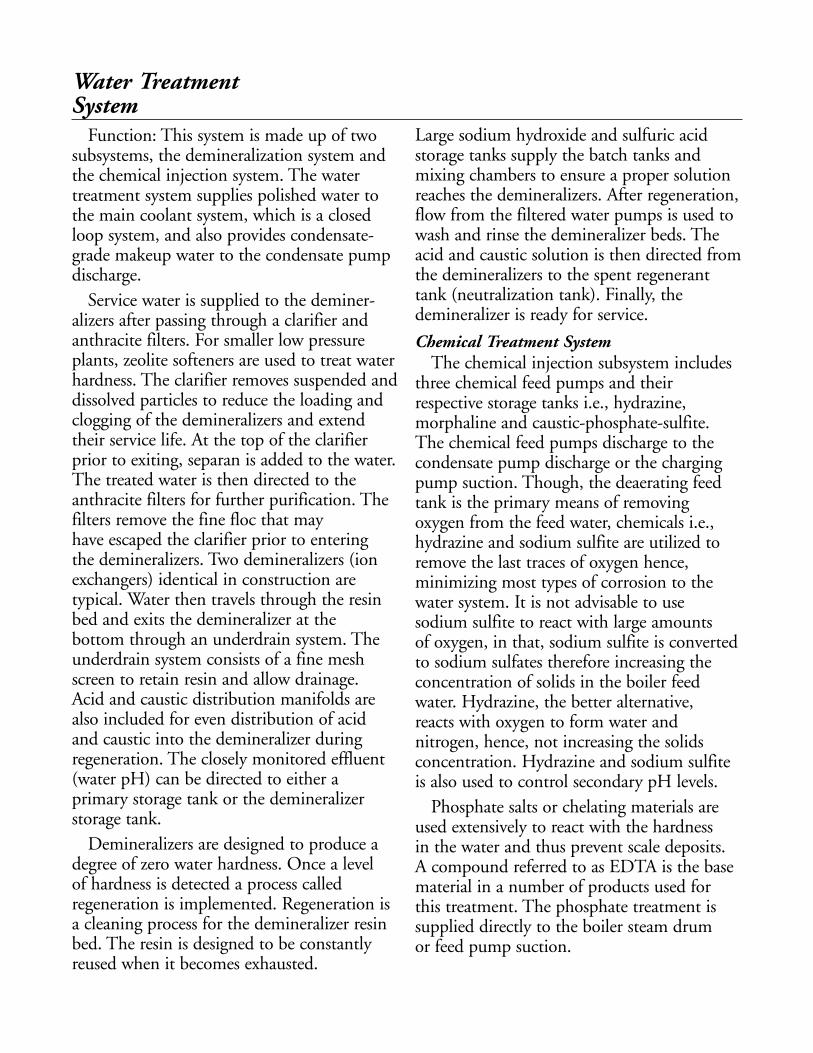
Function: This system is made up of twosubsystems, the demineralization system andthe chemical injection system. The watertreatment system supplies polished water tothe main coolant system, which is a closedloop system, and also provides condensate-grade makeup water to the condensate pumpdischarge.
Service water is supplied to the deminer-alizers after passing through a clarifier andanthracite filters. For smaller low pressureplants, zeolite softeners are used to treat waterhardness. The clarifier removes suspended anddissolved particles to reduce the loading andclogging of the demineralizers and extendtheir service life. At the top of the clarifierprior to exiting, separan is added to the water.The treated water is then directed to theanthracite filters for further purification. Thefilters remove the fine floc that may have escaped the clarifier prior to entering the demineralizers. Two demineralizers (ionexchangers) identical in construction aretypical. Water then travels through the resinbed and exits the demineralizer at the bottom through an underdrain system. Theunderdrain system consists of a fine meshscreen to retain resin and allow drainage. Acid and caustic distribution manifolds arealso included for even distribution of acid and caustic into the demineralizer duringregeneration. The closely monitored effluent(water pH) can be directed to either aprimary storage tank or the demineralizerstorage tank.
Demineralizers are designed to produce adegree of zero water hardness. Once a level of hardness is detected a process calledregeneration is implemented. Regeneration isa cleaning process for the demineralizer resinbed. The resin is designed to be constantlyreused when it becomes exhausted.
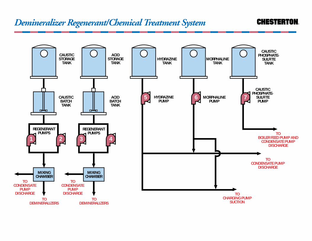
Large sodium hydroxide and sulfuric acidstorage tanks supply the batch tanks andmixing chambers to ensure a proper solutionreaches the demineralizers. After regeneration,flow from the filtered water pumps is used towash and rinse the demineralizer beds. Theacid and caustic solution is then directed fromthe demineralizers to the spent regeneranttank (neutralization tank). Finally, thedemineralizer is ready for service.
Chemical Treatment SystemThe chemical injection subsystem includes
three chemical feed pumps and theirrespective storage tanks i.e., hydrazine,morphaline and caustic-phosphate-sulfite.The chemical feed pumps discharge to thecondensate pump discharge or the chargingpump suction. Though, the deaerating feedtank is the primary means of removingoxygen from the feed water, chemicals i.e.,hydrazine and sodium sulfite are utilized toremove the last traces of oxygen hence,minimizing most types of corrosion to thewater system. It is not advisable to use sodium sulfite to react with large amounts of oxygen, in that, sodium sulfite is convertedto sodium sulfates therefore increasing theconcentration of solids in the boiler feedwater. Hydrazine, the better alternative, reacts with oxygen to form water andnitrogen, hence, not increasing the solidsconcentration. Hydrazine and sodium sulfiteis also used to control secondary pH levels.
Phosphate salts or chelating materials areused extensively to react with the hardness in the water and thus prevent scale deposits. A compound referred to as EDTA is the basematerial in a number of products used for this treatment. The phosphate treatment issupplied directly to the boiler steam drum or feed pump suction.
Water Treatment System
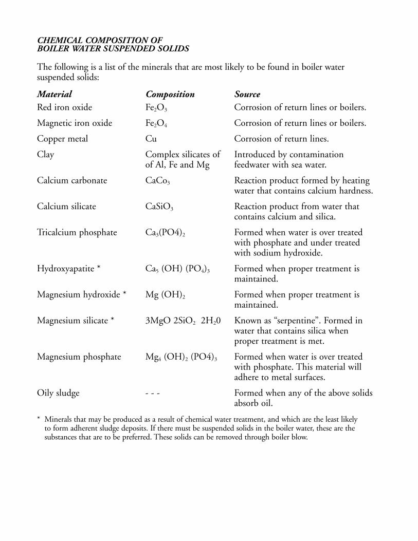
CHEMICAL COMPOSITION OFBOILER WATER SUSPENDED SOLIDS
The following is a list of the minerals that are most likely to be found in boiler watersuspended solids:
Material Composition SourceRed iron oxide Fe2O3 Corrosion of return lines or boilers.
Magnetic iron oxide Fe2O4 Corrosion of return lines or boilers.
Copper metal Cu Corrosion of return lines.
Clay Complex silicates of Introduced by contamination of Al, Fe and Mg feedwater with sea water.
Calcium carbonate CaCo3 Reaction product formed by heating water that contains calcium hardness.
Calcium silicate CaSiO3 Reaction product from water that contains calcium and silica.
Tricalcium phosphate Ca3(PO4)2 Formed when water is over treated with phosphate and under treated with sodium hydroxide.
Hydroxyapatite * Ca5 (OH) (PO4)3 Formed when proper treatment is maintained.
Magnesium hydroxide * Mg (OH)2 Formed when proper treatment is maintained.
Magnesium silicate * 3MgO 2SiO2 2H20 Known as “serpentine”. Formed in water that contains silica when proper treatment is met.
Magnesium phosphate Mg4 (OH)2 (PO4)3 Formed when water is over treated with phosphate. This material will adhere to metal surfaces.
Oily sludge - - - Formed when any of the above solids absorb oil.
* Minerals that may be produced as a result of chemical water treatment, and which are the least likely to form adherent sludge deposits. If there must be suspended solids in the boiler water, these are the substances that are to be preferred. These solids can be removed through boiler blow.

Water Demineralizer System ®
CLARIFIER
HOTWEL
SERVICEWATERSUPPLY
FILTERED WATERSTORAGE TANK
TO PORTABLE DEMINERALIZER
MIXEDBED
DEMINERALIZER
MIXEDBED
DEMINERALIZER
3BACKWASH
PUMP
PRIMARY WATERSTORAGE TANK
FROM PORTABLEDEMINERALIZER
TOCHEMICAL MIXING
FEED TANKSANTHRACITE
GRAVITY FILTERS
1
2
4
REGENERANTNEUTRALIZATION
TANK
CLAYFEED TANK
SEPARANFEED TANK
CAUSTICHYPOCHLORITE
FEED TANK
ALUMINUMFEED TANK
65
TODEMINERALIZER
EDUCTOR
FILTERED WATER PUMP

Water Demineralizer System
PUMP PUMP TEMP. SEAL API NOTESNO. RECOMMENDATION PLAN1+2 FILTER PUMPS AMB. 155 SC/CB, EP NONE
891 CB/SC, EP442 RSC/CB, EP
3 BACKWASH AMB. 155 SC/CB, EP NONE891 CB/SC, EP442 RSC/CB, EP
4 CAUSTIC AMB. 155 SC/DC, EP PLAN 13 1,2(HYPOCHLORITE) 891 TC/SC, EP PLAN 13 1,2
5 ALUMINUM AMB. 155 SC/SC, EP PLAN 13 2891 SC/SC, EP PLAN 13 2225 SC/SC/SC/CB, EP PLAN 53
6 SEPARAN AMB.
Notes:1. Requires ALLOY-20 or HASTELLOY-C metallurgy.2. A Plan 32, off the service water supply, may be possible.
REGENERANTPUMPS
TODEMINERALIZERS
3 4
TOCONDENSATE
PUMPDISCHARGE
®
CAUSTICSTORAGE
TANK
5
Demineralizer Regenerant/Chemical Treatment System
ACIDSTORAGE
TANKHYDRAZINE
TANKMORPHALINE
TANK
CAUSTICPHOSPHATE-
SULFITETANK
CAUSTICBATCHTANK
ACIDBATCHTANK
REGENERANTPUMPS
TODEMINERALIZERS
1 2
MIXINGCHAMBER
TOCONDENSATE
PUMPDISCHARGE
HYDRAZINEPUMP
TOCHARGING PUMP
SUCTION
TOCONDENSATE PUMP
DISCHARGE
MORPHALINEPUMP
CAUSTICPHOSPHATE-
SULFITEPUMP
TOBOILER FEED PUMP AND
CONDENSATE PUMPDISCHARGE
6 7
MIXINGCHAMBER

Demineralizer Regenerant/Chemical Treatment System
PUMP PUMP TEMP. SEAL API NOTESNO. RECOMMENDATION PLAN
1 CAUSTIC AMB. 155 TC/CB, EP PLAN 32 1,3,4REGENERANT 225 SSC/CB/SSC/CB,EP PLAN 53 1,5
891 CB/SSC, EP PLAN 32 1,3,42 CAUSTIC AMB. 155 TC/CB, EP PLAN 32 1,3,4
REGENERANT 225 SSC/CB/SSC/CB, EP PLAN 53 1,5891 CB/SSC, EP PLAN 32 1,3,4
3 ACID AMB. 155 SSC/RSC, VITON PLAN 13 2(SULFURIC) 225 SSC/RSC/SSC/CB,VITON PLAN 53 2
440 CB/SSC, VITON NONE4 ACID AMB. 155 SSC/RSC, VITON PLAN 13 2
(SULFURIC) 225 SSC/RSC/SSC/CB, VITON PLAN 53 2440 CB/SSC
5 HYDRAZINE AMB. 155 RSC/CB, EP NONE225 RSC/CB/SSC/CB, EP PLAN 53
6 MORPHALINE AMB.7 CAUSTIC AMB. 155 TC/DC, VITON PLAN 32 6
PHOSPHATE- 225 TC/DC/SSC/CB, VITON PLAN 53 6SULFITE
Notes:1. At concentrations <50% standard seal materials can be used. Concentrations exceeding 50% requires
HASTELLOY-C metallurgy and SSC/TC seal faces. Ethylene propylene is required at any concentration.2. A standard seal can be used in concentrations <5% and >95%. For concentrations >5% or <95% use
SSC/RSC and ALLOY-20 metallurgy. Lead Oxide Viton* and Kalrez* are used for concentrations > 30%. 658RC carbon for concentrations < 75%. 6038-C2 acid grade carbon for concentrations between 75-98%.
3. At concentrations exceeding 50% or if crystallization is a problem an API Gland with a steam quench is recommended.
4. A Plan 32, off the service water supply to the demineralizers, may be possible5. RSC and DC are limited to concentrations < 5%.6. No 658RC carbon.
*DuPont’s registered trademark
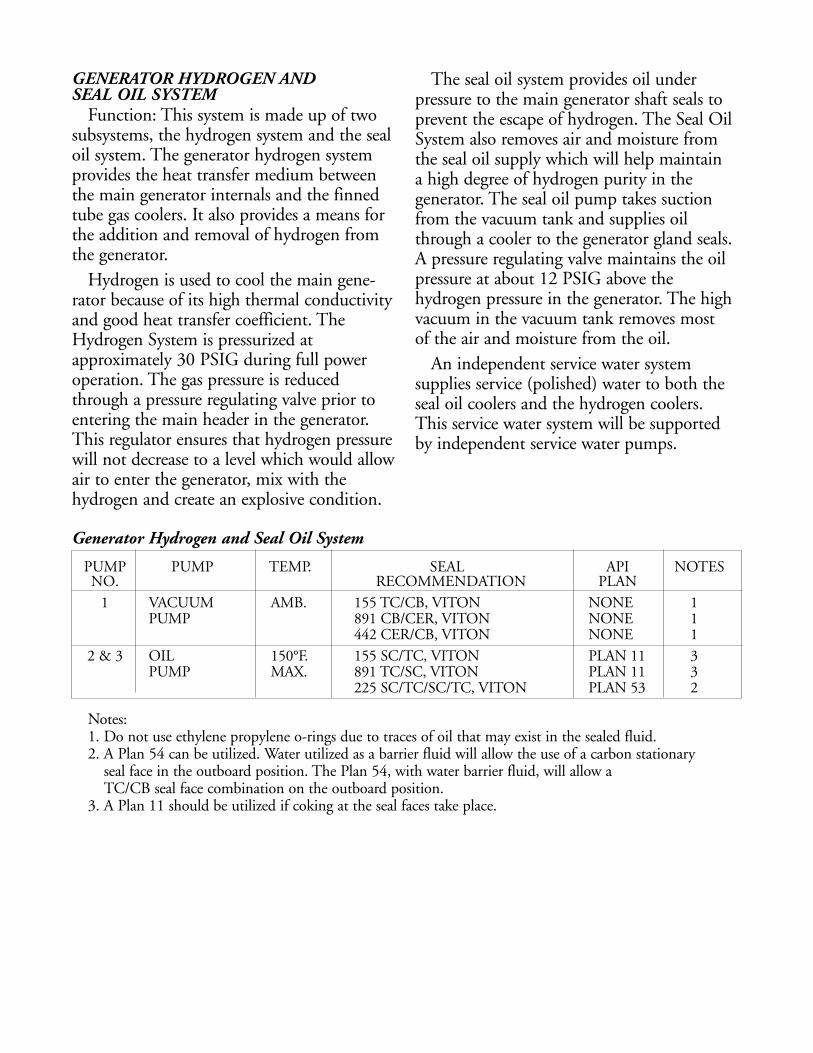
Generator Hydrogen and Seal Oil System
PUMP PUMP TEMP. SEAL API NOTESNO. RECOMMENDATION PLAN
1 VACUUM AMB. 155 TC/CB, VITON NONE 1 PUMP 891 CB/CER, VITON NONE 1
442 CER/CB, VITON NONE 1 2 & 3 OIL 150°F. 155 SC/TC, VITON PLAN 11 3
PUMP MAX. 891 TC/SC, VITON PLAN 11 3225 SC/TC/SC/TC, VITON PLAN 53 2
GENERATOR HYDROGEN AND SEAL OIL SYSTEM
Function: This system is made up of twosubsystems, the hydrogen system and the sealoil system. The generator hydrogen systemprovides the heat transfer medium betweenthe main generator internals and the finnedtube gas coolers. It also provides a means forthe addition and removal of hydrogen fromthe generator.
Hydrogen is used to cool the main gene-rator because of its high thermal conductivityand good heat transfer coefficient. TheHydrogen System is pressurized atapproximately 30 PSIG during full poweroperation. The gas pressure is reducedthrough a pressure regulating valve prior toentering the main header in the generator.This regulator ensures that hydrogen pressurewill not decrease to a level which would allowair to enter the generator, mix with thehydrogen and create an explosive condition.
The seal oil system provides oil underpressure to the main generator shaft seals toprevent the escape of hydrogen. The Seal OilSystem also removes air and moisture fromthe seal oil supply which will help maintain a high degree of hydrogen purity in thegenerator. The seal oil pump takes suctionfrom the vacuum tank and supplies oilthrough a cooler to the generator gland seals.A pressure regulating valve maintains the oilpressure at about 12 PSIG above thehydrogen pressure in the generator. The highvacuum in the vacuum tank removes most of the air and moisture from the oil.
An independent service water systemsupplies service (polished) water to both theseal oil coolers and the hydrogen coolers. This service water system will be supportedby independent service water pumps.
Notes:1. Do not use ethylene propylene o-rings due to traces of oil that may exist in the sealed fluid.2. A Plan 54 can be utilized. Water utilized as a barrier fluid will allow the use of a carbon stationary
seal face in the outboard position. The Plan 54, with water barrier fluid, will allow a TC/CB seal face combination on the outboard position.
3. A Plan 11 should be utilized if coking at the seal faces take place.

Generator Seal Oil System ®
1
OILCOOLER
FROMGOVERNOROIL SUPPLY
SERVICEWATER
SERVICE WATERSUPPLY FROM
BEARING OILHEADER
3
HYDROGEN SIDEDRAIN TANK
A.C.PUMP
2D.C.
PUMP
VACUUMTANK
AIR SIDEDRAIN TANK
GENERATOR
COLLECTION TANK

THE NEW STANDARD FOR RELIABILITY®
POWER INDUSTRY
IV. Basic Nuclear Power Cycles
MECHANICAL SEALDIVISION

The Rankine cycle is the basis for theproduction of electricity by nuclear reactors.In light water reactors, the basic cycle isutilized in the direct cycle and the indirectcycle.
Pressurized Water Reactor (PWR)The pressurized water reactor utilizes the
indirect cycle. It has two separate closedloops: the primary loop, which circulatespressurized water from the reactor, adjacent to the fuel rods, through the steam generatorto give up thermal energy; the secondary loopwhere the steam is generated is the heat sink.This steam is used to turn a high speed steamturbine and electrical generator throughshafting. The indirect cycle requires more heatexchangers, pumps and auxiliary equipmentthan the direct cycle, since two separate closedloops must be maintained. Though there is a slight efficiency loss with the indirect cycle,the advantages are offset by the advantages of isolating the primary fluid; precludes thebuildup of radioactive products and thecontamination of secondary components.
Boiling Water Reactor (BWR)The boiling water reactor utilizes the direct
cycle. One loop of pressurized water is thesame as the secondary loop of the indirectcycle, except that the steam generator, ratherthan the reactor, is the direct heat source inthe cycle. In other words, the conversion of water to steam takes place in the reactorloop adjacent to the fuel rods.
IV. Basic Nuclear Power Cycle

Boiling Water Reactor®
REACTOR(STEAM
GENERATOR)
STEAM
FEEDWATERPUMP
1
COOLINGMEDIUM
IN
GENERATORTURBINE
CONDENSER
COOLINGMEDIUM
OUT
TURBINE EXHAUST
TOCONDENSER

Pressure Water Reactor ®
COOLINGMEDIUM
IN
GENERATOR
REACTOR
TURBINESTEAM
GENERATOR
PRIMARY LOOP SECONDARY LOOP
CONDENSER
REACTORCOOLANT
PUMP
FEEDWATERPUMP
2
1
COOLINGMEDIUM
OUT
TURBINE EXHAUST
STEAMHOT WATER
THE NEW STANDARD FOR RELIABILITY®
POWER INDUSTRY
V. Nuclear Specific SystemsMain Coolant SystemLPST Makeup And Chemical Control System (Boric Acid)Shutdown Cooling SystemPurification SystemRadioactive Waste Disposal SystemComponent Cooling SystemFuel Handling SystemSpent Fuel Pit Cooling SystemPrimary Seal Water SystemEngineered Safety Systems
Emergency Core CoolingSafe Shutdown System
MECHANICAL SEALDIVISION
MAIN COOLANT SYSTEM (PWR)Function: The function of the Main
Coolant System is to transfer heat producedby the reactor core to the water in the steamgenerators via the primary coolant loop. The heat carried from the reactor coreproduces steam in a secondary loop and isutilized to drive the turbine. The heat transfermedium in the Main Coolant System isborated water which also acts as themoderator and reflector for the reactor core.The boron in the water helps control corereactivity. The boron concentration varies(decreases) over the life of the core to near 0 PPM at the end of core life. The MainCoolant System also provides a barrier againstthe release of radioactive fission productswhich are produced in the reactor core. The system is designed to operate at 2500 PSIA and 650°F.
System ComponentsSteam Generator (secondary loop): Serves
as the link between the primary andsecondary loops. It is here where the steam isgenerated by the transfer of heat from thehigh temperature coolant water in theprimary loop (borated water) to the secondaryloop (feed water). Pressurized water reactorplants utilize a closed-loop-system designprinciple. This means the radioactive coolantin the reactor cycle is completely separatedfrom the turbine-generator cycle. The designpressure and temperature for the secondaryside of the steam generator is 1050 PSIG and600°F respectively.
Pressurizer: Is a vertical, cylindrical pressurevessel with spherical upper and lower heads.The pressurizer maintains the water in theMain Coolant System below the saturationpoint. It is normally about one-third full ofwater with the remaining volume filled withsteam vapor. Electric heaters located in thebottom of the pressurizer are used to heat thewater to 636°F. The saturated steam pressureat this point is 2000 PSIG. This pressure istransmitted through the surge line to theMain Coolant System.
CHARGING AND VOLUME CONTROL SYSTEM
Function: The charging and volume controlsystem provides a path for boration ordilution of the main coolant system. It alsocontrols the pressurizer level by varying thespeed of the charging pumps; provides ameans for adding chemicals to the MainCoolant System; and is used to cool down the pressurizer during a plant shut down. The system typically has three positivedisplacement charging pumps, two variablespeed and one fixed speed. Normally, onevariable speed pump is running with its speedbeing controlled by pressurizer level.
V. NuclearSpecific Systems

LPST MAKEUP AND CHEMICALCONTROL SYSTEM
Function: The Low Pressure Surge Tanksystem is used to control reactor power andMain Coolant System temperature duringpower operation and reactor shutdown byadjusting the amount of boric acid dissolvedin the main coolant. Boric acid contains twoisotopes of Boron: Boron-10 and Boron-11.The addition of boric acid to the MainCoolant System will absorb neutrons thus,causing a reduction in reactor power outputand Main Coolant System temperature.
The LPST System can supply a strongconcentration of boric acid (12.0-12.5%) or a weak solution equal to or greater than2200 ppm. The boric acid is supplied to thecharging pump suction for injection into theMain Coolant System. Demineralized watercan also be supplied to the charging pumpsuction for boron dilution operations. The LPST System is typically equipped with two single stage centrifugal pumps.
System ComponentsBoric Acid Mix Tank: The tank serves to
store a certain volume of 12.0-12.5 wt %boric acid solution. Heaters in the tankmaintain the temperature at 170°F to preventthe boric acid from precipitating out ofsolution. A man way is provided at the top of the tank and is used for adding boric acid. To obtain 12 wt % boric acid solution onepound of boric acid is added to one gallon of demineralized water. A two speed motordriven agitator is used to thoroughly mix thecontents of the tank.
Boric Acid Transfer Pump: The boric acidtransfer pump is a single stage centrifugalpump used to supply a strong boric acidsolution to primary systems.
SHUTDOWN COOLING SYSTEMFunction: The Shutdown Cooling System
removes heat generated by radioactive decayof fission products in the reactor core duringextended shutdown periods. The heatgenerated by decay of fission products canreach 6-7% of full power after an extendedrun and will take several months to decreaseto less than 0.1%. The Shutdown System isplaced into service when the Main CoolantSystem is less than 325°F and pressure is lessthan 300 PSIG.
System ComponentsShutdown Cooling PumpShutdown Cooler
PURIFICATION SYSTEMFunction: The objective of the Purification
System is to remove soluble and insoluble impurities from the reactor coolant. Theseimpurities include corrosion products,uranium oxide and associated fissionproducts. The system can also be used toremove boric acid from the main coolant near the end of core life, which will minimizethe volume of waste water.
System ComponentsPurification Cooling and Drain PumpsIon Exchangers and Filters
RADIOACTIVE WASTE DISPOSAL SYSTEM
Function: Serves to maintain a balancedwater inventory in the waste disposal tanks,such that little or no purified liquid wastedischarge from the plant is necessary. Thismay be accomplished by recycling purifiedwaste to primary plant makeup.
The Waste Disposal System may be dividedinto three general systems: the liquid radwastesystem, the gaseous radwaste system and thesolid radwaste system.
System ComponentsLiquid and gas storage tanksEvaporatorsPump compressorsFiltersHeat Exchangers
COMPONENT COOLING SYSTEMFunction: The Component Cooling System
dissipates waste heat from nuclear plant equipment which may contain radioactivefluid. The system is a closed-loop coolingsystem which acts as a barrier to reduce thepossibility of leakage of radioactive fluids tothe environment. The system also provides asource of make up to the neutron shield tankand the waste gas header loop seal. TheComponent Cooling Water is the coolingmedium for the LPST, Shutdown and SpentFuel Pit Coolers. Either one of the highcapacity Component Cooling Pumps listedbelow, can handle the full system heat load.
System Components(2) Component Cooling PumpsComponent Cooling CoolersLPST and Shutdown Cooling CoolersSpent Fuel Pit CoolersWaste Disposal BuildingVapor ContainerComponent Cooling Surge TankCorrosion Control Pot
FUEL HANDLING SYSTEMFunction: Provides a means for refueling
the reactor core and the transfer of spent fuelrods to a designated storage tank. The NewFuel Vault Provides a place to store new fuelassemblies as well as other core components.The spent fuel pit is adjacent to the New FuelVault and is used to store irradiated fuelassemblies. These storage areas are adjacent to the nuclear reactor.
There are normally two Spent Fuel TankPumps which service the Spent Fuel Tank and are housed nearby.
SPENT FUEL PIT COOLING SYSTEM Function: The Spent Fuel Pit Cooling
System serves to remove decay heat from the irradiated fuel assemblies which are stored in the Spent Fuel Pit submerged indemineralized water. The system also purifiesthe water in the spent fuel pit. Two pumps areprovided for this system. One pump isnormally running while the other serves as abackup. The pump in operation takes suctionfrom the Spent Fuel Pit and dischargingthrough the tube side of the Spent Fuel PitCooler. Some of the SFP water can be sentthrough and ion exchanger for purificationand returned to the Spent Fuel Pit.
System ComponentsTank(2) SFP PumpsDewatering PumpCoolerIon Exchanger
PRIMARY SEAL WATER SYSTEMFunction: The purpose of the Primary Seal
Water System is to supply seal water to theshaft seals on the LPST cooling pump, the shutdown cooling pump, and the twopurification pumps. This will reduce thepossibility of the release of radioactivematerial if the pump seals develop a leak. The seal water tank, which holds a reservoirof water for the primary pump seals, holdsapproximately 35 gallons and is pressurizedwith a nitrogen blanket to a minimumpressure of 50 PSIG greater than the highestdischarge pressure of any pump being sealed.There are normally two seal water pumpswhich service this system.
System Components Tank(2) PumpsCooler
ENGINEERED SAFETY SYSTEMSEmergency Core Cooling System
Function: The Emergency Core CoolingSystem is designed to inject borated waterinto the Main Coolant System to cool thereactor core following a loss-of-coolantaccident or an uncontrolled cool downsituation. This injection of borated water will help maintain the water inventory of theMain Coolant System and ensure an adequateshutdown margin for the reactor core. A lossof coolant accident is defined as: a leak fromthe main coolant system which is in excess of the make up flow from the operable MainCoolant System charging pumps. The SafetyInjection System is also used to fill the reactorshield tank cavity during refueling operations.
Low Pressure Safety Injection (LPSI)The system requires three multistage, high
flow, centrifugal pumps with a minimumTDH of 1100 feet at 3600 RPM.
High Pressure Safety Injection (HPSI)The system requires three multistage, low
flow, centrifugal pumps with a minimumTDH of 1500 feet at 1750 RPM.
Safe Shutdown SystemFunction: In response to federal guidelines
regarding seismic design considerations andfire protection requirements this system wasmandated. This system is used to bring theplant to a cold shutdown within 72 hoursafter a seismic event or during a transientcaused by fire located in either the MainControl Room, switchgear room or turbinebuilding which requires evacuation of thecontrol room. It can also be used to bring the plant to a cold shutdown should a fireoccur in the Safety Injection/Diesel GeneratorBuilding that results in a station blackout.
The Safe Shutdown System providesprimary makeup and emergency feed to thesteam generator during these conditions. The SSS is totally independent of all otherplant systems. It consists of two pumps; onefor charging the Main Coolant System andone to provide feedwater to the steamgenerators. Electric power is supplied to thesepumps by its own diesel generator set.