check valves - armatury group
TRANSCRIPT

CHECK VALVES

COMPANY PROFILE
The company ARMATURY Group a.s. is a leading Czech manufacturer and distributor of industrial valves, fittings and control systems for valves. The annual production is of more than 100 000 valves and 500 000 metallurgical stock items.
The company was established January 1, 2000. The tradition of our young and dynamically deve-loping company is closely linked with the more than fifty-years’ history of valve production in the Hlučín Region.
Our products have been supplied to local and foreign customersfor the following industries:
• power engineering, nuclear power• chemical and petrochemical• gas supply• metallurgical industry• water supply

Check valves acc. to EN
Type C09.5 Butterfly swing check valves . . . . . . . . . . . . . . . . . . . . . . . . .4
Types L10.1, L10.2 Check valves . . . . . . . . . . . . . . . . . . . . . . . . . . . . . . . . . . . . . . . .8
Type L10.3 Check valves . . . . . . . . . . . . . . . . . . . . . . . . . . . . . . . . . . . . . . .10
Check valves acc. to ASME
Type C09.5 Butterfly swing check valves . . . . . . . . . . . . . . . . . . . . . . . .13
Type L10.3 Check valves . . . . . . . . . . . . . . . . . . . . . . . . . . . . . . . . . . . . . . .16
Table of pressure-temperature ratings . . . . . . . . . . . . . . .19
Certification . . . . . . . . . . . . . . . . . . . . . . . . . . . . . . . . . . . . . . . .22
Type number composition . . . . . . . . . . . . . . . . . . . . . . . . . .23
CONTENT

www.armatur ygroup.cz4
BUTTERFLY SWING CHECK VALVES TYPE C09.5
ApplicationThe butterfly swing check valves are self-acting and fast-closing valves which prevent a working medium from flowing back in a pipeline. They are used in order to prevent from backflow the pumps, fans etc. The check valve is not a shut-off valve.
Working mediumWater, air, steam and other non-aggressive liquids and gases. The fluid flow direction may be only from one side of the valve. The fluid flow direction is marked with an arrow on the valve body.
Working temperatureService temperature depends on the material of seals. - 46°C up to 300 °C
Technical descriptionThe valve disc, eccentrically embedded, rotates inside a flanged end fabricated body. The shaft is clamped in the self-lubricated fric-tion bearings. Outside the valve on the end of the shaft there is the lever with counterweight.
OperationThe swing check valves are automatic, quick-acting valves. Move-ment of the disc is controlled by the flowing fluid.
TestingThe butterfly swing check valves are tested for strength and leak-age, functionality and tightness acc. to EN 12 266 section 1, leakage grade is D (grade B on request) or acc. to API 598.
Connection to piping flanged ends acc. to EN 1092-1, EN 1759-1 or GOST 12815-80
face to face dimension acc. to EN 558 welded ends acc. to EN 12 627
face to face dimension acc. to EN 12 982
InstallationThe butterfly swing check valves can be mounted into a horizon-tal or a vertical piping so that the arrow on the valve stamped in the valve body corresponds to the flow direction of the working medium, the valve disc rotation axis is in a horizontal position and above axis of flowing (only a horizontal piping). If the valve is to be mounted in a vertical piping, the working medium will have to flow upwards.
Advantages possibility of installation into vertical, horizontal
or inclined pipings low pressure loss fabricated design, which allows us flexibility (no castings) maintenance free and long service life design variability one-piece body minimization of water hammer
15 46 32
Material acc. to EN
Position ComponentCarbon steel
For low temperatures from -46 °C to +300 °C
For normal temperatures from -20 °C to +300 °C *
1 Body
1.0566 1.0425, 1.05772 Disc
3 Cover
4 Shaft 1.4021 1.4021
5 Sealing surface 13Cr x 13Cr 13Cr x 13Cr
6 Packing TURKON NBR, EPDM, VITON, TURKON*
* - the temperature in accordance with the applied seal material

www.armatur ygroup.czwww.armaturygroup.cz 5
BUTTERFLY SWING CHECK VALVES TYPE C09.5
DN 100-1600 • PN 6-100 • Tmax +300 °CBody design: fabricated or forged
DN D1 D2 D3 d n a f L A B Kv 100 % kg
100 210 170 148 18 4 18 3 300 120 265 330 49
125 240 200 178 18 8 20 3 325 135 280 535 58
150 265 225 202 18 8 20 3 210 150 280 810 35
200 320 280 258 18 8 22 3 230 176 267 1500 40
250 375 335 312 18 12 24 3 250 230 320 2410 55
300 440 395 365 22 12 24 4 270 250 340 3530 68
350 490 445 415 22 12 26 4 290 270 360 5030 108
400 540 495 465 22 16 28 4 310 276 380 6640 148
500 645 600 570 22 20 30 4 350 450 590 10400 240
600 755 705 670 26 20 32 5 390 495 675 15200 320
700 860 810 775 26 24 40 5 430 538 720 20800 515
800 975 920 880 30 24 44 5 470 572 814 27100 695
1000 1175 1120 1080 30 28 52 5 550 687 890 42600 1060
1200 1405 1340 1295 33 32 60 5 630 780 1010 61800 1320
1400 1630 1560 1510 36 36 72 5 710 970 1250 84100 2450
1600 1830 1760 1710 36 40 80 5 790 1080 1380 109800 2990
Kv 100 % [m3/h] – a coefficient of flow Kv expresses the rate of flow with pressure drop 1 bar across the full open valve in one hour
Connection: EN 1092-1, ISO 7005-1 FLANGED ENDS EN 12 627 WELDED ENDS
PN 6
D1
D3
DN
n x d
f
La
D2
A B

www.armatur ygroup.cz6
DN 100-1600 • PN 6-100 • Tmax +300 °CBody design: fabricated or forged
DN D1 D2 D3 d n a f L A B Kv 100 % kg100 220 180 158 18 8 22 3 300 120 265 330 49125 250 210 188 18 8 22 3 325 135 280 535 58150 285 240 212 22 8 24 3 210 150 280 810 45200 340 295 268 22 8 24 3 230 176 274 1500 44250 395 350 320 22 12 26 3 250 230 320 2410 60300 445 400 370 22 12 26 4 270 250 340 3530 90350 505 460 430 22 16 30 4 290 270 360 5030 130400 565 515 482 26 16 32 4 310 292 363 6640 160500 670 620 585 26 20 38 4 350 440 600 10400 230600 780 725 685 30 20 42 5 390 495 675 15200 360700 895 840 800 30 24 50 5 430 538 720 20800 530800 1015 950 905 33 24 56 5 470 572 814 27100 710
1000 1230 1160 1110 36 28 70 5 550 687 890 42600 12051200 1455 1380 1330 39 32 83 5 630 830 1100 61800 19001400 1675 1590 1535 42 36 65 5 710 970 1250 84100 26001600 1915 1820 1760 48 40 75 5 790 1080 1380 109800 3550
DN D1 D2 D3 d n a f L A B Kv 100 % kg100 220 180 158 18 8 22 3 300 120 265 330 49125 250 210 188 18 8 22 3 325 135 280 535 58150 285 240 212 22 8 24 3 210 150 280 810 50200 340 295 268 22 12 26 3 230 176 267 1500 54250 405 355 320 26 12 29 3 250 230 320 2410 70300 460 410 378 26 12 32 4 270 315 470 3530 93350 520 470 438 26 16 35 4 290 270 435 5030 150400 580 525 490 30 16 38 4 310 300 370 6640 190500 715 650 610 33 20 46 4 350 440 600 10400 260600 840 770 725 36 20 55 5 390 495 680 15200 390700 910 840 795 36 24 63 5 430 540 720 20800 570800 1025 950 900 39 24 74 5 470 572 814 27100 740
1000 1255 1170 1115 42 28 90 5 550 687 890 42600 13151200 1485 1390 1330 48 32 78 5 630 830 1100 61800 23001400 1685 1590 1530 48 36 84 5 710 970 1250 84100 31001600 1930 1820 1750 56 40 102 5 790 1080 1380 109800 3920
BUTTERFLY SWING CHECK VALVES TYPE C09.5
Kv 100 % [m3/h] – a coefficient of flow Kv expresses the rate of flow with pressure drop 1 bar across the full open valve in one hour
Connection: EN 1092-1, ISO 7005-1 FLANGED ENDS EN 12 627 WELDED ENDS
PN 10
PN 16
DN D1 D2 D3 d n a f L A B Kv 100 % kg100 235 190 162 22 8 26 3 300 120 265 330 50125 270 220 188 26 8 28 3 325 135 280 535 59150 300 250 218 26 8 30 3 210 150 280 810 58200 360 310 278 26 12 32 3 230 176 270 1500 65250 425 370 335 30 12 35 3 250 235 330 2410 85300 485 430 395 30 16 38 4 270 245 387 3530 111350 555 490 450 33 16 42 4 290 270 440 4850 181400 620 550 505 36 16 48 4 310 300 370 6400 230500 730 660 615 36 20 58 4 350 407 615 10100 300600 845 770 720 39 20 68 5 390 500 690 14700 450700 960 875 820 42 24 85 5 430 550 750 20100 670800 1085 990 930 48 24 95 5 470 572 914 26300 1060
1000 1320 1210 1140 56 28 63 5 550 700 950 41300 15201200 1530 1420 1350 56 32 86 5 630 840 1150 59400 2500
PN 25

www.armatur ygroup.czwww.armaturygroup.cz 7
BUTTERFLY SWING CHECK VALVES TYPE C09.5
DN D1 D2 D3 d n a f L A B Kv 100 % kg
100 250 200 162 26 8 32 3 300 130 260 330 60
125 295 240 188 30 8 34 3 325 145 290 535 68
150 345 280 218 33 8 36 3 350 150 295 790 80
200 415 345 285 36 12 48 3 400 240 343 1450 125
250 470 400 345 36 12 55 3 450 260 380 2330 160
300 530 460 410 36 16 65 4 500 315 405 3420 240
350 600 525 465 39 16 72 4 550 340 464 4720 350
400 670 585 535 42 16 80 4 600 385 516 6220 450
500 800 705 615 48 20 70 4 700 435 570 9800 700
600 930 820 735 56 20 76 5 800 520 690 14300 980
700 1045 935 840 56 24 95 5 900 560 790 19500 1310
800 1165 1050 960 62 24 115 5 1000 680 910 25500 1680
DN D1 D2 D3 d n a f L A B Kv 100 % kg
100 265 210 162 30 8 36 3 300 130 260 330 60
125 315 250 188 33 8 42 3 325 145 290 535 68
150 355 290 218 33 12 48 3 350 160 295 790 75
200 430 360 285 36 12 60 3 400 247 343 1450 135
250 505 430 345 39 12 72 3 450 255 380 2330 220
300 585 500 410 42 16 84 4 500 320 415 3420 372
350 655 560 465 48 16 95 4 550 340 464 4720 520
400 715 620 535 48 16 76 4 600 385 516 6220 680
500 870 760 615 56 20 89 4 700 440 580 9800 990
DN D1 D2 D3 d n a f L A B Kv 100 % kg
100 235 190 162 22 8 26 3 300 120 250 330 55
125 270 220 188 26 8 28 3 325 135 280 535 65
150 300 250 218 26 8 30 3 350 150 280 810 75
200 375 320 285 30 12 36 3 400 180 280 1500 110
250 450 385 345 33 12 42 3 450 240 340 2410 165
300 515 450 410 33 16 52 4 500 260 400 3530 200
350 580 510 465 36 16 58 4 550 315 450 4850 280
400 660 585 535 39 16 65 4 600 340 515 6400 400
500 755 670 615 42 20 57 4 700 445 580 10100 590
600 890 795 735 48 20 72 5 800 510 684 14700 810
700 995 900 840 48 24 86 5 900 550 780 20100 1150
800 1140 1030 960 56 24 99 5 1000 670 890 26300 1490
1000 1360 1250 1180 56 28 115 5 1200 720 970 41300 2205
1200 1575 1460 1380 62 32 134 5 630 850 1160 59400 2950
DN 100-1600 • PN 6-100 • Tmax +300 °CBody design: fabricated or forged
PN 40
PN 63
PN 100
Kv 100 % [m3/h] – a coefficient of flow Kv expresses the rate of flow with pressure drop 1 bar across the full open valve in one hour
Connection: EN 1092-1, ISO 7005-1 FLANGED ENDS EN 12 627 WELDED ENDS

www.armatur ygroup.cz8
CHECK VALVES TYPE L10.1, L10.2
ApplicationSwing check valves are self-acting valves preventing the back flow of the fluid. It is used especially in power engineering, chemical industry as well as other industries depending on material selection. Swing check valves are not shut-off valves.
Working medium water steam gas other fluids
Working temperature -20 °C up to 650 °C
Technical descriptionThe body is made of forged material. The disc is inserted into the valve body through the pressure seal cover joint or through the self-sealing body-cover joint. The seat ring is welded in the body and its seating surface and disc surface of the disc are hard faced. The cover is sealed by a special graphite gasket. Upon request, the valves may be equipped with a bypass.
Design configurations L10.1 - with bolted cover L10.2 - with pressure seal cover
Operation self-acting operation
TestingValves are subject to shell strength test, shell tightness test, seat tightness test and functionality test according to EN 12266, API 598 with water as a standard. If required, other tests may be performed as well.
Connection to the piping flanged ends acc. to EN 1092-1, ISO 7005-1, GOST 12815-80 welded ends acc. to EN 12627
InstallationSwing check valves may be installed into horizontal piping with the cover upwards or into vertical piping, but the flow direction is bottom up. The flow direction shall correspond to the arrow on the valve body.
1
6
2
3
5
4
L10.2
Material acc. to EN Position Component Tmax 450 °C Tmax 450 °C Tmax 530 °C Tmax 560 °C Tmax 570 °C Tmax 600 °C Tmax 650 °C
1 Body P250GH (1.0460)
15NiCuMoNb5-6-4 (1.6368)
16Mo3 (1.5415)
13CrMo4-5 (1.7335)
14MoV6-3 (1.7715)
11CrMo9-10 (1.7383)
X10CrMoVNb9-1 (1.4903)
2 Bonnet
3 Disc
4 Seat + overlay 1.0460 +Stellite 1.6368 +Stellite 1.5415 +Stellite 1.7335 +Stellite 1.7715 +Stellite 1.7383 +Stellite 1.4903 +Stellite
5 Disc + overlay 1.0460 +Stellite 1.6368 +Stellite 1.5415 +Stellite 1.7335 +Stellite 1.7715 +Stellite 1.7383 +Stellite 1.4903 +Stellite
6 Gasket L10.1 PN 63, 100, 160, 250, - Graphite with stainless steel insert, L10.2 PN 160, 250, 320, 400, - Graphite

www.armatur ygroup.czwww.armaturygroup.cz 9
CHECK VALVES TYPE L10.1, L10.2
fg
Dp
Do
Dz
do x
n
L
DN 50-400 • PN 63-400 • Tmax 650 °C (450 °C)Body design: forged
PN 63, 100, 160, 250
TYPE L10.1 TYPE L10.2
PN 160, 250, 320, 400
Connection: EN 1092-1, ISO 7005-1 , GOST 12815-80 FLANGED ENDS EN 12627 WELDED ENDS
L
L
d1 dp d
fg
L
d1 dp
H1
H2
do x
n
D1
D2
D3
welded ends welded ends
flanged ends
PN DN/d d1 * dp L * Lmin* H1 H2 kg
160-400**
65/50 77
Acc.
to or
der
360 216 65 240 2580/75 90 450 305 85 255 47
100/75 115 450 406 85 280 48125/110 141 500 483 115 315 107150/110 170 550 559 115 365 110175/125 180 650 559 145 405 285175/150 196 650 660 160 405 415200/150 222 650 660 160 485 445225/175 248 650 660 180 520 715250/200 276 800 787 200 590 930250/225 303 900 787 220 630 980300/225 325 900 914 220 700 1410300/250 325 1000 991 240 700 1520350/275 359 1000 991 270 760 1710400/300 411 1200 1092 310 825 1830
* dimensions d1 and L can be adjusted according to customer request, ** TYPE L10.1 is supplied only up to PN 250
PN DNWelded ends Flanged ends
d1 dp L H1 kgD1 D3
D2 do x n L g f kgGOST EN GOST EN
63
50 62 54 250 170 12 175 180 102 135 22 x 4 300 26 3 1865 77 69 290 190 17 200 205 122 160 22 x 8 340 26 3 2580 91 81 310 205 22 210 215 133 138 170 22 x 8 380 28 3 32
100 117 104 350 220 33 250 158 162 200 26 x 8 430 30 3 45125 144 130,5 400 254 50 295 184 188 240 30 x 8 500 34 3 68150 172 156,5 450 305 80 340 345 212 218 280 33 x 8 550 36 3 100200 223 204,5 550 406 105 405 415 285 345 36 x 12 650 42 3 153250 278 255 650 508 200 470 345 400 36 x 12 775 46 3 248
100
50 62 54 250 170 13,2 195 102 145 26 x 4 300 28 3 20,765 77 69 290 190 18,7 220 122 170 26 x 8 340 30 3 28,880 91 81 310 205 24,2 230 133 138 180 26 x 8 380 32 3 36,8
100 117 104 350 220 36,3 265 158 162 210 30 x 8 430 36 3 51,8125 144 127 400 254 55,0 310 315 184 188 250 33 x 8 500 40 3 78,2150 172 154 450 305 88,0 350 355 212 218 290 33 x 12 550 44 3 115,0200 223 199,5 550 406 115,5 430 285 360 36 x 12 650 52 3 176,0250 278 248,5 650 508 220,0 500 505 345 430 39 x 12 775 60 3 285,2
PN 63-100
PN 160-400
L10.1
L10.2

www.armatur ygroup.cz10
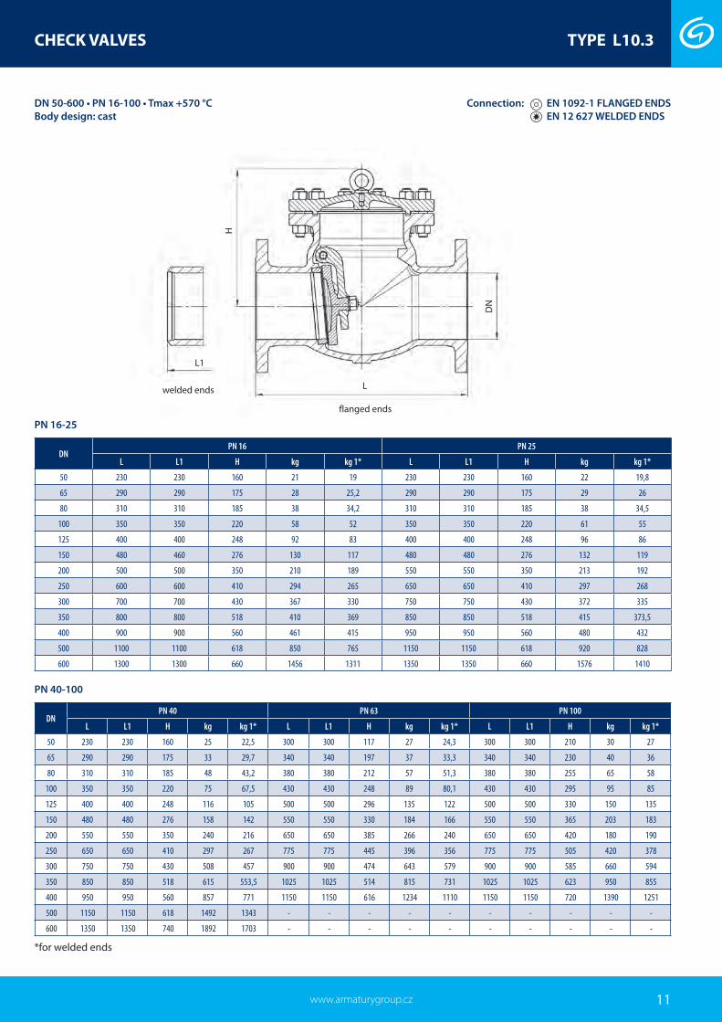
CHECK VALVES TYPE L10.3
ApplicationThe check valves are self-acting valves which prevent a working medium from flowing back in a pipeline.
Working mediumWater, sea water, water steam, air, oil, oil products, other non-aggressive liquids group 1 and 2.
Working temperatureThe working temperature is in dependence on material design in range from -50 °C to +570 °C.
Technical descriptionThe check valves are made from cast steel with full port. The sealing surface of the disc bears on the overlay of seat (austenitic stainless steel). The disc with an arm rotates on hinge and is pushed to the seat by its own weight. Connection flanges are integral part of the body. The cover is connected with body by bolts with graphite gas-ket. They consist of a body, a cover, a seat, a disc and an arm. The allowed maximum working pressure in dependence on temperatu-re is noted in pressure-temperature table.
Design configurations with lever with bypass with lever and bypass Design in accordance - for petroleum, oil and gas. Valve in the open position allows free mixing of the pressure, cleaning or measuring.
Operation self-acting
TestingThe swing check valves are tested acc. to EN 12 266-1, API 598 for strength and leakage of body and leakage of a cover.
Connection to piping flanged ends acc. to EN 1092-1 design B1 standard se-aling surface (on customer’s request DIN 2526 form C, form E). Face to face dimensions are acc. to EN 558.
welded ends acc. to EN 12 627. Face to face dimensions are acc. to EN 12 982.
InstallationThe check valves can be mounted into a horizontal ( with top side bonnet) and a vertical piping so that the arrow on the valve stam-ped in the valve body corresponds to the flow direction of the wor-king medium.
Advantages wide range of working parameters possibility to repair sealing surfaces without uninstallation of swing check valves pipeline.8
29
3
1
7
56
4
Material acc. to EN
Position ComponentCarbon steel
from -20 °C to 450 °CAlloy steel
from -10 °C to 570 °CCarbon steel for low temperatures
from -40 °C to 300 °CStainless steel
from -50 °C to 550 °C1 Body 1.0619 1.7357 1.6220 1.44082 Bonnet 1.0619 1.7357 1.6220 1.44083 Disc + overlay 1.0619 + 13Cr 1.7357 + Stellite 6 1.6220 + F304 1.44084 Seat ring + overlay 1.0460 + 13Cr 1.7335 + Stellite 6 1.0566 + Stellite 6 1.4408 5 Arm 1.0619 1.7357 1.6220 1.44086 Arm pin 1.4006 1.4301 1.4401 1.44017 Bonnet nut 1.1191* 1.7709* 1.7225* 1.4401*8 Bonnet bolt 1.7218* 1.7709* 1.7225* 1.4401*9 Bonnet sealing Graphite with stainless steel insert
* equivalent or acc. to customer’s request
www.armatur ygroup.czwww.armaturygroup.cz 11
CHECK VALVES TYPE L10.3
DNPN 16 PN 25
L L1 H kg kg 1* L L1 H kg kg 1*
50 230 230 160 21 19 230 230 160 22 19,8
65 290 290 175 28 25,2 290 290 175 29 26
80 310 310 185 38 34,2 310 310 185 38 34,5
100 350 350 220 58 52 350 350 220 61 55
125 400 400 248 92 83 400 400 248 96 86
150 480 460 276 130 117 480 480 276 132 119
200 500 500 350 210 189 550 550 350 213 192
250 600 600 410 294 265 650 650 410 297 268
300 700 700 430 367 330 750 750 430 372 335
350 800 800 518 410 369 850 850 518 415 373,5
400 900 900 560 461 415 950 950 560 480 432
500 1100 1100 618 850 765 1150 1150 618 920 828
600 1300 1300 660 1456 1311 1350 1350 660 1576 1410
DN 50-600 • PN 16-100 • Tmax +570 °CBody design: cast
DNPN 40 PN 63 PN 100
L L1 H kg kg 1* L L1 H kg kg 1* L L1 H kg kg 1*
50 230 230 160 25 22,5 300 300 117 27 24,3 300 300 210 30 27
65 290 290 175 33 29,7 340 340 197 37 33,3 340 340 230 40 36
80 310 310 185 48 43,2 380 380 212 57 51,3 380 380 255 65 58
100 350 350 220 75 67,5 430 430 248 89 80,1 430 430 295 95 85
125 400 400 248 116 105 500 500 296 135 122 500 500 330 150 135
150 480 480 276 158 142 550 550 330 184 166 550 550 365 203 183
200 550 550 350 240 216 650 650 385 266 240 650 650 420 180 190
250 650 650 410 297 267 775 775 445 396 356 775 775 505 420 378
300 750 750 430 508 457 900 900 474 643 579 900 900 585 660 594
350 850 850 518 615 553,5 1025 1025 514 815 731 1025 1025 623 950 855
400 950 950 560 857 771 1150 1150 616 1234 1110 1150 1150 720 1390 1251
500 1150 1150 618 1492 1343 - - - - - - - - - -
600 1350 1350 740 1892 1703 - - - - - - - - - -
DN
H
L
L1
Connection: EN 1092-1 FLANGED ENDS EN 12 627 WELDED ENDS
PN 16-25
PN 40-100
*for welded ends
welded ends
flanged ends

www.armatur ygroup.cz12
CHECK VALVES TYPE L10.3
1
4
5
2
3
Position ComponentCarbon steel
from -29°C to 425°C Carbon steel for low temperatures
from -46°C to 350°C
1 Body A216 WCB A 352 LCC
2 Bonnet 1.0425 A350 LF2
3 Disc + overlay 1.0425 + Stellite A 350 LF2 + Stellite
4 Seat + overlay 1.0425 + Stellite A 350 LF2 + Stellite
5 Arm 1.0425 A 350 LF2
*other materials upon request
DN 300-900 • PN 40-100 • Tmax +425°C Body design: castDesign in accordance with the standard EN 14141 and ISO 14313.Full bore valve
Connection: EN 1092-1 FLANGED ENDS EN 12 627 WELDED ENDS
DN PN Ø d Ø D2 H H1 H2Flanged ends Welded ends
Ø D C3 L kg Ø D1 Ø Dp L1 kg300
40
303 550 750 320 430 515 42 850 870 329
acc.
to or
der
838 820400 385 675 1004 380 624 660 50 1100 1050 413 991 928600 589 930 1300 550 750 890 60 1450 2890 619 1397 2700700 684 1150 1800 550 1250 995 70 1650 3990 721 1600 3830300
63
303 550 750 320 430 530 52 900 920 329 838 820400 385 675 1004 380 624 670 60 1150 1130 413 991 928600 589 930 1300 550 750 930 72 1600 2970 619 1397 2700700 684 1150 1800 550 1250 1045 85 1650 4250 721 1600 3830300
100
303 550 750 320 430 585 68 900 945 329 838 820400 385 675 1004 380 624 715 78 1150 1150 413 991 928600 589 930 1300 550 750 - - - - 619 1397 2700700 684 1150 1800 550 1250 - - - - 721 1600 3830
PN 40-100
LC3
Ø D2
Ø D
Ø d
H H
H2
H2
H1
H1
Ø D
1
Ø D
p
Ø d
Ø D2
L1
Material

www.armatur ygroup.czwww.armaturygroup.cz 13
BUTTERFLY SWING CHECK VALVES TYPE C09.5
ApplicationThe butterfly swing check valves are self-acting and fast-closing valves which prevent a working medium from flowing back in a pipeline. They are used in order to prevent from backflow the pumps, fans etc. The check valve is not a shut-off valve.
Working mediumWater, air, steam and other non-aggressive liquids and gases. The fluid flow direction may be only from one side of the valve. The fluid flow direction is marked with an arrow on the valve body.
Working temperatureService temperature depends on the material of seals. - 46°C up to 300 °C
Technical descriptionThe valve disc, eccentrically embedded, rotates inside a flanged end fabricated body. The shaft is clamped in the self-lubricated fric-tion bearings. Outside the valve on the end of the shaft there is the lever with counterweight.
OperationThe swing check valves are automatic, quick-acting valves. Move-ment of the disc is controlled by the flowing fluid.
TestingThe butterfly swing check valves are tested for strength and leak-age, functionality and tightness acc. to EN 12 266 section 1, leakage grade is D (grade B on request) or acc. to API 598.
Connection to piping flanged acc. to ASME B16.5
face to face dimmension acc. to API Spec 6D welded acc. to ASME B16.25
face to face acc. to API Spec 6D
InstallationThe butterfly swing check valves can be mounted into a horizon-tal or a vertical piping so that the arrow on the valve stamped in the valve body corresponds to the flow direction of the working medium, the valve disc rotation axis is in a horizontal position and above axis of flowing (only a horizontal piping). If the valve is to be mounted in a vertical piping, the working medium will have to flow upwards.
Advantages possibility of installation into vertical, horizontal
or inclined pipings low pressure loss fabricated design, which allows us flexibility (no castings) maintenance free and long service life design variability one-piece body minimization of water hammer
15 46 32
Material acc. to ASTM
Position ComponentCarbon steel
For low temperatures from -46 °C to +300 °C
For normal temperatures from -20 °C to +300 °C *
1 Body
A350 LF2A515 Gr.60A537 Cl.1
2 Disc
3 Cover
4 Shaft A182 F6a A182 F6a
5 Sealing surface 13Cr x 13Cr 13Cr x 13Cr
6 Packing TURKON NBR, EPDM, VITON, TURKON*
* - the temperature in accordance with the applied seal material

www.armatur ygroup.cz14
BUTTERFLY SWING CHECK VALVES TYPE C09.5
Kv 100 % [m3/h] – a coefficient of flow Kv expresses the rate of flow with pressure drop 1 bar across the full open valve in one hour
NPS D1 D2 D3 d n a f L A B Kv 100 % kg4 228,6 190,5 157,2 19,1 8 23,9 1,6 300 120 265 330 495 254 215,9 185,7 22,4 8 23,9 1,6 325 135 280 535 586 279,4 241,3 215,9 22,4 8 25,4 1,6 210 150 280 810 558 342,9 298,5 269,7 22,4 8 28,4 1,6 230 176 270 1500 67
10 406,4 362 323,9 25,4 12 30,2 1,6 250 235 330 2410 9312 482,6 431,8 381 25,4 12 31,8 1,6 270 245 387 3530 12514 533,4 476,3 412,8 28,4 12 35,1 1,6 290 270 440 4850 19216 596,9 539,8 469,9 28,4 16 36,6 1,6 310 300 370 6400 24420 698,5 635 584,2 31,8 20 42,9 1,6 350 407 615 10100 33824 812,8 749,3 692,2 35,1 20 47,8 1,6 390 500 690 14700 52328 927,1 863,6 800,1 35,1 28 71,4 1,6 430 550 750 20100 74032 1060,5 977,9 914,4 41,2 28 80,8 1,6 470 572 914 26300 96540 1289,1 1200,2 1124 41,2 36 90,5 1,6 550 700 950 41300 164048 1511,3 1422,4 1358,9 41,2 44 108 1,6 630 840 1150 59400 2760
NPS D1 D2 D3 d n a f L A B Kv 100 % kg
4 254 200,1 157,2 22,3 8 31,7 1,6 300 120 250 330 575 279,4 234,9 185,6 22,3 8 35 1,6 325 135 280 535 686 317,5 269,7 215,9 22,3 12 36,5 1,6 350 150 280 810 798 381 330,2 269,7 25,4 12 41,1 1,6 400 180 280 1500 117
10 444,5 387,3 323,8 28,4 16 47,7 1,6 450 240 340 2410 16712 520,7 450,8 381 31,7 16 50,8 1,6 500 260 400 3530 21614 584,2 514,3 412,7 31,7 20 53,8 1,6 550 315 450 4850 32616 647,7 571,5 469,9 35 20 57,1 1,6 600 340 515 6400 42620 774,7 685,8 584,2 35 24 63,5 1,6 700 445 580 10100 62924 914,4 812,8 692,1 41,1 24 69,8 1,6 800 510 684 14700 86028 1035,1 939,8 800,1 44,5 28 85,9 1,6 900 550 780 20100 125532 1149,4 1054,1 914,4 50,8 28 98,7 1,6 1000 670 890 26300 162840 1238,3 1155,7 1085,9 44,5 32 114,3 1,6 1200 720 970 41300 238848 1466,9 1371,6 1301,8 50,8 32 133,6 1,6 630 850 1160 59400 3450
Class 150
Class 300
D1
D3
DN
n x d
f
La
D2
A B
NPS 4-48 • Class 150-600 • Tmax +300 °C Connection: ASME B16.5 FLANGED ENDS ASMEB16.25 WELDED ENDS

www.armatur ygroup.czwww.armaturygroup.cz 15
TYPE C09.5BUTTERFLY SWING CHECK VALVES
NPS 4-48 • Class 150-600 • Tmax +300 °C
NPS D1 D2 D3 d n a f L A B Kv 100 % kg
4 254 200,2 157,2 25,4 8 35,1 6,4 300 130 260 330 63
5 279,4 235 185,7 25,4 8 38,1 6,4 325 145 290 535 72
6 317,5 269,7 215,9 25,4 12 41,1 6,4 350 150 295 790 81
8 381 330,2 269,7 28,4 12 47,8 6,4 400 240 343 1450 140
10 444,5 387,4 323,9 31,8 16 53,8 6,4 450 260 380 2330 174
12 520,7 450,9 381 35,1 16 57,2 6,4 500 315 405 3420 260
14 584,2 514,4 412,8 35,1 20 60,5 6,4 550 340 464 4720 380
16 647,7 571,5 469,9 38,1 20 63,5 6,4 600 385 516 6220 600
20 774,7 685,8 584,2 41,1 24 69,9 6,4 700 435 570 9800 820
24 914,4 812,8 692,2 47,8 24 76,2 6,4 800 520 690 14300 1075
28 1035,1 939,8 800,1 50,8 28 95,3 6,4 900 560 790 19500 1460
32 1149,4 1054,1 914,4 53,9 28 114,35 6,4 1000 680 910 25500 1830
NPS D1 D2 D3 d n a f L A B Kv 100 % kg
4 273,1 215,9 157,2 25,4 8 38,1 6,4 300 130 260 330 63
5 330,2 266,7 185,7 28,4 8 44,5 6,4 325 145 290 535 73
6 355,6 292,1 215,9 28,4 12 47,8 6,4 350 160 295 790 83
8 419,1 349,3 269,7 31,8 12 55,6 6,4 400 247 343 1450 175
10 508 431,8 323,9 35,1 16 63,5 6,4 450 255 380 2330 236
12 558,8 489 381 35,1 20 66,5 6,4 500 320 415 3420 389
14 603,3 527,1 412,8 38,1 20 69,9 6,4 550 340 464 4720 538
16 685,8 603,3 469,9 41,1 20 76,2 6,4 600 385 516 6220 719
20 812,8 723,9 584,2 44,5 24 88,9 6,4 700 440 580 9800 1095
Class 400
Class 600
Kv 100 % [m3/h] – a coefficient of flow Kv expresses the rate of flow with pressure drop 1 bar across the full open valve in one hour
Connection: ASME B16.5 FLANGED ENDS ASMEB16.25 WELDED ENDS

www.armatur ygroup.cz16
CHECK VALVES TYPE L10.3
ApplicationThe check valves are self-acting valves which prevent a working medium from flowing back in a pipeline.
Working mediumWater, sea water, water steam, air, oil, oil products, other non-aggressive liquids group 1 and 2.
Working temperatureThe working temperature is in dependence on material design in range from -50 °C to +595 °C.
Technical descriptionThe check valves are made from cast steel with full port. The sealing surface of the disc bears on the overlay of seat (austenitic stainless steel). The disc with an arm rotates on hinge and is pushed to the seat by its own weight. Connection flanges are integral part of the body. The cover is connected with body by bolts with graphite gas-ket. They consist of a body, a cover, a seat, a disc and an arm. The allowed maximum working pressure in dependence on temperatu-re is noted in pressure-temperature table.
Design configurations with lever with bypass with lever and bypass Design in accordance - for petroleum, oil and gas. Valve in the open position allows free mixing of the pressure, cleaning or me-asuring
Operation self-acting
TestingThe swing check valves are tested acc. to API 598, EN 12 266-1 for strength and leakage of body and leakage of a cover.
Connection to piping flanged acc. to ASME B16.5, ASME B16.25 welded acc. to ASME B16.25
InstallationThe check valves can be mounted into a horizontal (with top side bonnet) and a vertical piping so that the arrow on the valve stam-ped in the valve body corresponds to the flow direction of the wor-king medium.
Advantages wide range of working parameters possibility to repair sealing surfaces without uninstallation of swing check valves pipeline.
8
29
3
1
7
56
4
Material acc. to ASTM
Position ComponentCarbon steel
from -29 °C to 425 °CAlloy steel
from -29 °C to 595 °CCarbon steel for low temperatures
from -46 °C to 345 °CStainless steel
from -50 °C to 538 °C1 Body A216 WCB A217 WC6 A352 LCC A351 CF8M2 Bonnet A216 WCB A217 WC6 A352 LCC A351 CF8M
3 Disc + overlay A216 WCB + 13Cr A217 WC6 + Stellite 6 A352 LCC + F304 A351 CF8M
4 Seat ring + overlay A105 + 13Cr A182 F11 + Stellite 6 A350 LF2 + Stellite 6 A351 CF8M 5 Arm A216 WCB A217 WC6 A352 LCC A351 CF8M6 Arm pin A276 420 A182 F304 A182 F316 A182 F3167 Bonnet nut A194 2H* A194 4* A194 7M* A194 8M*8 Bonnet bolt A193 B7* A193 B16* A320 L7M* A193 B8M*9 Bonnet sealing Graphite with stainless steel insert
* equivalent or acc. to customer’s request

www.armatur ygroup.czwww.armaturygroup.cz 17
CHECK VALVES TYPE L10.3
NPS 2-30 • Class 150-600 • Tmax +595 °C Connection: ASME B16.5 FLANGED ENDS ASMEB16.25 WELDED ENDS
NPS DN
Class 150 Class 300 Class 600
LH kg
LH kg
LH kg
RF BW RF RTJ BW RF RTJ BW
2 50 203 203 132 15 267 283 267 144 20 292 295 292 170 28
2 1/2 65 216 216 147 20 292 308 292 169 35 330 333 330 178 40
3 80 241 241 176 27 318 333 318 210 40 356 359 356 246 68
4 100 292 292 198 45 356 371 356 260 61 432 435 432 290 117
5 125 330 330 255 58 400 416 400 295 80 508 511 508 320 155
6 150 356 356 320 69 445 460 445 326 130 559 562 559 360 192
8 200 495 495 380 131 533 549 533 380 190 660 664 660 430 340
10 250 622 622 440 219 622 638 622 440 296 787 791 787 502 515
12 300 699 699 480 321 711 727 711 520 450 838 841 838 554 750
14 350 787 787 530 380 838 854 838 540 640 889 892 889 595 890
16 400 864 864 580 560 864 879 864 588 850 991 994 991 680 1303
18 450 978 978 618 630 978 994 978 670 1030 1092 1095 1092 778 1800
20 500 978 978 657 770 1016 1035 1016 720 1330 1194 1200 1194 970 2150
24 600 1295 1295 760 960 1346 1368 1346 850 1950 1397 1407 1397 1100 3200
26 650 1295 1295 840 1250 1346 1372 1346 920 2300 - - - - -
28 700 1448 1448 920 1580 1499 1524 1499 1150 2600 - - - - -
30 750 1524 1524 980 1950 1594 1619 1594 1260 3200 - - - - -
Class 150-600
H
NPS
LL
L
BW
RF RTJwelded ends
flanged ends

www.armatur ygroup.cz18
Material
1
4
5
2
3
Position ComponentCarbon steel
from -29°C to 425°C Carbon steel for low temperatures
from -46°C to 350°C
1 Body A216 WCB A 352 LCC
2 Bonnet 1.0425 A350 LF2
3 Disc + overlay 1.0425 + Stellite A 350 LF2 + Stellite
4 Seat + overlay 1.0425 + Stellite A 350 LF2 + Stellite
5 Arm 1.0425 A 350 LF2
*other materials upon request
NPS 12-28 • Class 150-600 • Tmax +425 °CBody design: castDesign in accordance with the standard API 6D. Full bore valve
Connection: ASME B16.5, ASME B16.47 FLANGED ENDS ASME B16.25 WELDED ENDS
NPS PN Ø d Ø D2 H H1 H2Flanged ends Welded ends
Ø D C3 L kg Ø D1 Ø Dp L1 kg12
40
303 550 750 320 430 485 32 699 870 329
acc.
to or
der
838 82016 385 675 1004 380 624 595 37 864 1050 413 991 92824 589 930 1300 550 750 815 48 1295 2890 619 1397 270028 684 1150 1800 550 1250 925 72 1448 3990 721 1600 383012
63
303 550 750 320 430 520 51 711 920 329 838 82016 385 675 1004 380 624 650 57 864 1130 413 991 92824 589 930 1300 550 750 915 72 1346 2970 619 1397 270028 684 1150 1800 550 1250 1035 86 1499 4250 721 1600 383012
100
303 550 750 320 430 560 74 838 945 329 838 82016 385 675 1004 380 624 685 84 991 1150 413 991 92824 589 930 1300 550 750 940 109 1397 3150 619 1397 270028 684 1150 1800 550 1250 - - - - 721 1600 3830
Class 150-600
LC3
Ø D2
Ø D
Ø d
H H
H2
H2
H1
H1
Ø D
1
Ø D
p
Ø d
Ø D2
L1
CHECK VALVES TYPE L10.3

www.armatur ygroup.czwww.armaturygroup.cz 19
Connection: ASME B16.5, ASME B16.47 FLANGED ENDS ASME B16.25 WELDED ENDS
CHECK VALVES
Body material Material class Maximum allowable working pressure - in bar Temperature 20 °C 100 °C 150 °C 200 °C 250 °C 300 °C 350 °C 400 °C 450 °C 500 °C 550 °C 560 °C 570 °C 580 °C 590 °C 600 °C
1.0425 (P265GH) 3E0 2,5 2,3 2,2 2,0 1,9 1,7 1,6 1,4 0,8 - - - - - - - 1.0566 (P355NL1) 7E1 2,5 2,5 2,5 2,5 2,5 2,4 2,2 1,9 - - - - - - - -
1.4541 (X6CrNiTi18-10) 12E0 2,5 2,4 2,3 2,2 2,1 1,9 1,9 1,8 1,8 1,7 1,6 1,5 1,4 1,2 1,1 1
Body material Material class Maximum allowable working pressure - in bar Temperature 20 °C 100 °C 150 °C 200 °C 250 °C 300 °C 350 °C 400 °C 450 °C 500 °C 550 °C 560 °C 570 °C 580 °C 590 °C 600 °C
1.0619 (GP240GH) 3E0 10,0 9,2 8,8 8,3 7,6 6,9 6,4 5,9 3,2 - - - - - - -1.7335 (13CrMo45) 5E0 10,0 10,0 10,0 10,0 10,0 9,9 9,5 9,0 8,5 6,5 - - - - - -
1.4541 (X6CrNiTi18-10) 12E0 10,0 9,9 9,3 8,8 8,4 7,9 7,6 7,4 7,2 7 6,7 6,1 5,6 5 4,5 4 1.4408 (GX5CrNiMo19-11-2) 14E0 10,0 10,0 9,0 8,4 7,9 7,4 7,1 6,8 6,7 6,6 6,5 - - - - -
Body material Material class Maximum allowable working pressure - in bar Temperature 20 °C 100 °C 150 °C 200 °C 250 °C 300 °C 350 °C 400 °C 450 °C 500 °C 550 °C 560 °C 570 °C 580 °C 590 °C 600 °C
1.0425 (P265GH) 3E0 6,0 5,5 5,2 5,0 4,5 4,1 3,8 3,5 1,9 - - - - - - - 1.0619 (GP240GH) 3E0 6,0 9,2 8,8 8,3 7,6 6,9 6,4 5,9 3,2 - - - - - - -1.7335 (13CrMo45) 5E0 6,0 6,0 6,0 6,0 6,0 5,9 5,7 5,4 5,1 3,9 - - - - - - 1.0566 (P355NL1) 7E1 6,0 6,0 6,0 6,0 6,0 5,8 5,4 4,7 - - - - - - - -
1.4541 (X6CrNiTi18-10) 12E0 6,0 5,9 5,6 5,3 5 4,7 4,6 4,4 4,3 4,2 4 3,6 3,3 3 2,7 2,4 1.4408 (GX5CrNiMo19-11-2) 14E0 6,0 10,0 9,0 8,4 7,9 7,4 7,1 6,8 6,7 6,6 6,5 - - - - -
1.0577 (S355J2G3) 6,0 5,9 5,4 - - - - - - - - - - - - -
Body material Material class Maximum allowable working pressure - in bar Temperature 20 °C 100 °C 150 °C 200 °C 250 °C 300 °C 350 °C 400 °C 450 °C 500 °C 550 °C 560 °C 570 °C 580 °C 590 °C 600 °C
1.0425 (P265GH) 3E0 16,0 14,8 14,0 13,3 12,1 11,0 10,2 9,5 5,2 - - - - - - - 1.0566 (P355NL1) 7E1 16,0 16,0 16,0 16,0 16,0 15,6 14,4 12,7 - - - - - - - - 1.0619 (GP240GH) 3E0 16,0 14,8 14,0 13,3 12,1 11,0 10,2 9,5 5,2 - - - - - - -
1.7357 (G17CrMo5-5) 5E0 16,0 16,0 16,0 16,0 16,0 15,9 15,2 14,4 13,7 10,4 3,7 3,0 2,5 - - - 1.6220 (G20Mn5) 7E1 16,0 16,0 16,0 16,0 16,0 15,6 - - - - - - - - - -
1.4541 (X6CrNiTi18-10) 12E0 16,0 15,8 14,9 14,1 13,4 12,7 12,2 11,8 11,6 11,3 10,8 9,8 8,9 8,1 7,3 6,5
1.4408 (GX5CrNiMo19-11-2) 14E0 16,0 16,0 14,5 13,4 12,7 11,8 11,4 10,9 10,7 10,5 10,4 - - - - -
1.0577 (11 523) 16,0 15,8 14,5 - - - - - - - - - - - - -
1.7335 (13CrMo45) 5E0 16,0 16,0 16,0 16,0 16,0 15,9 15,2 14,4 13,7 10,4 - - - - - -
Body material Material class Maximum allowable working pressure - in bar Temperature 20 °C 100 °C 150 °C 200 °C 250 °C 300 °C 350 °C 400 °C 450 °C 500 °C 550 °C 560 °C 570 °C 580 °C 590 °C 600 °C
1.0425 (P265GH) 3E0 25,0 23,2 22,0 20,8 19,0 17,2 16,0 14,8 8,2 - - - - - - - 1.0619 (GP240GH) 3E0 25,0 23,2 22,0 20,8 19,0 17,2 16,0 14,8 8,2 - - - - - - -
1.7357 (G17CrMo5-5) 5E0 25,0 25,0 25,0 25,0 25,0 24,8 23,8 22,6 21,4 16,3 5,8 4,7 3,9 - - - 1.7335 (13CrMo45) 5E0 25,0 25,0 25,0 25,0 25,0 24,8 23,8 22,6 21,4 16,3 - - - - - - 1.0566 (P355NL1) 7E1 25,0 25,0 25,0 25,0 25,0 24,5 22,6 19,8 - - - - - - - - 1.6220 (G20Mn5) 7E1 25,0 25,0 25,0 25,0 25,0 24,5 - - - - - - - - - -
1.4541 (X6CrNiTi18-10) 12E0 25,0 24,7 23,3 22,1 21 19,8 19,1 18,5 18,1 17,7 16,9 15,3 14 12,7 11,4 10,2
1.4408 (GX5CrNiMo19-11-2) 14E0 25,0 25,0 22,7 21,0 19,8 18,5 17,8 17,1 16,8 16,5 16,3 - - - - -1.0577 (11 523) 25,0 24,7 22,7 - - - - - - - - - - - - -
TABLE OF PRESSURE-TEMPERATURE RATINGSPS value are acc. to flange connection standard EN 1092-1.
PN 2,5
PN 10
PN 16
PN 25
PN 6

www.armatur ygroup.cz20
CHECK VALVES
Body material Material class Maximum allowable working pressure - in bar Temperature 20 °C 100 °C 150 °C 200 °C 250 °C 300 °C 350 °C 400 °C 450 °C 500 °C 550 °C 560 °C 570 °C 580 °C 590 °C 600 °C
1.0619 (GP240GH) 3E0 63,0 58,5 55,5 52,5 48,0 43,5 40,5 37,5 20,7 - - - - - - -1.7335 (13CrMo45) 5E0 63,0 63,0 63,0 63,0 63,0 62,7 60,0 57,0 54,0 41,1 - - - - - -
1.7357 (G17CrMo5-5) 5E0 63,0 63,0 63,0 63,0 63,0 62,7 60,0 57,0 54,0 41,1 14,7 12,0 9,9 - - - 1.6220 (G20Mn5) 7E1 63,0 63,0 63,0 63,0 63,0 61,8 - - - - - - - - - -
1.4541 (X6CrNiTi18-10) 12E0 63,0 62,4 58,8 55,8 53,1 50,1 48,3 46,8 45,7 44,7 42,6 38,7 35,4 32,1 28,8 25,8 1.4408 (GX5CrNiMo19-11-2) 14E0 63,0 63,0 57,3 53,1 50,1 46,8 45,0 43,2 42,4 41,7 41,1 - - - - -
1.0577 (11 523) 63,0 62,4 57,4 - - - - - - - - - - - - -
PN 63
Body material Material class Maximum allowable working pressure - in bar Temperature 20 °C 100 °C 150 °C 200 °C 250 °C 300 °C 350 °C 400 °C 450 °C 500 °C 550 °C 560 °C 570 °C 580 °C 590 °C 600 °C
1.0619 (GP240GH) 3E0 40,0 37,1 35,2 33,3 30,4 27,6 25,7 23,8 13,1 - - - - - - - 1.7335 (13CrMo45) 5E0 40,0 40,0 40,0 40,0 40,0 39,8 38,0 36,1 34,2 26,0 - - - - - -
1.7357 (G17CrMo5-5) 5E0 40,0 40,0 40,0 40,0 40,0 39,8 38,0 36,1 34,2 26,0 9,3 7,6 6,2 - - - 1.6220 (G20Mn5) 7E1 40,0 40,0 40,0 40,0 40,0 39,2 - - - - - - - - - -
1.4541 (X6CrNiTi18-10) 12E0 40,0 39,6 37,3 35,4 33,7 31,8 30,6 29,7 29 28,3 27 24,5 22,4 20,3 18,2 16,3 1.4408 (GX5CrNiMo19-11-2) 14E0 40,0 40,0 36,3 33,7 31,8 29,7 28,5 27,4 26,9 26,4 26,0 - - - - -
1.0577 (11 523) 40,0 39,6 36,4 - - - - - - - - - - - - -
PN 40
Body material Material class Maximum allowable working pressure - in bar Temperature 20 °C 100 °C 150 °C 200 °C 250 °C 300 °C 350 °C 400 °C 450 °C 500 °C 550 °C 560 °C 570 °C 580 °C 590 °C 600 °C
1.0619 (GP240GH) 3E0 100,0 92,8 88,0 83,3 76,1 69,0 64,2 59,5 32,8 - - - - - - -1.7335 (13CrMo45) 5E0 100,0 100,0 100,0 100,0 100,0 99,5 95,2 90,4 85,7 65,2 - - - - - -
1.7357 (G17CrMo5-5) 5E0 100,0 100,0 100,0 100,0 100,0 99,5 95,2 90,4 85,7 65,2 23,3 19,0 15,7 - - - 1.6220 (G20Mn5) 7E1 100,0 100,0 100,0 100,0 100,0 98,0 - - - - - - - - - -
1.4541 (X6CrNiTi18-10) 12E0 100,0 99 93,3 88,5 84,2 79,5 76,6 74,2 72,6 70,9 67,6 61,4 56,1 50,9 45,7 40,9 1.4408 (GX5CrNiMo19-11-2) 14E0 100,0 100,0 90,9 84,2 79,5 74,2 71,4 68,5 67,3 66,1 65,2 - - - - -
1.0577 (11 523) 100,0 99,1 91,1 - - - - - - - - - - - - -
PN 100
Body material Maximum allowable working pressure - in barTemperature 20 °C 100 °C 150 °C 200 °C 250 °C 300 °C 350 °C 400 °C 450 °C 480 °C 500 °C 520 °C 530 °C 540 °C 550 °C 560 °C 570 °C 580 °C 590 °C 600 °C
P250GH (C22.8) 1.0460 175,2 167,6 152,4 133,3 121,9 110,4 102,8 95,2 52,6 - - - - - - - - - - - 16Mo3 1.5415 197 179 160 144,8 133,3 114,3 110,5 106,7 102,9 100,6 70,9 45 35,8 - - - - - - - 13CrMo4-5 1.7335 194 182,9 171,4 160 152,4 141 133,3 125,7 118,1 115,8 104,4 71,6 59,4 46,5 37,3 30,5 25,1 - - -11CrMo9-10 (1.7383)
1.7380 190,5 178,7 171,2 163,8 156,2 148,6 141 133,3 125,7 121,1 102,9 78,5 68,6 59,4 51,8 44,2 38,9 33,5 29 25,9
14MoV6-3 1.7715 219 215 210 203 183,6 171,4 164,6 159,2 154,7 153,3 147 113,5 99,8 86,1 75,4 65,5 55,6 - - - 15NiCuMoNb5-6-4 1.6368 260 260 260 260 260 258 249 224 157 - - - - - - - - - - - GP240GH 1.0619 160 149 141 133 122 110 103 95,2 52,5 - - - - - - - - - - - G20Mo5 1.5419 160 160 160 160 156 137 130 122 118 89,7 70,8 44,9 35,8 - - - - - - - G17CrMo5-5 1.7357 186,7 172,1 161,2 160 160 159 152 145 137 117 104 71,6 59,4 46,4 37,3 30,4 - - - -
PN 160
Body material Maximum allowable working pressure - in barTemperature 20 °C 100 °C 150 °C 200 °C 250 °C 300 °C 350 °C 400 °C 450 °C 480 °C 500 °C 520 °C 530 °C 540 °C 550 °C 560 °C 570 °C 580 °C 590 °C 600 °C
P250GH (C22.8) 1.0460 274 262 238 208 184,5 160,7 136,9 107,1 82,1 - - - - - - - - - - - 16Mo3 1.5415 307 280 250 226 208 178,6 172,6 166,7 160,7 157,1 110,7 70,2 56 - - - - - - - 13CrMo4-5 1.7335 302 286 268 250 238 220 208 196 184,5 181 163,1 111,9 92,9 72,6 58,3 47,6 39,3 - - -11CrMo9-10 (1.7383)
1.7380 298 279 268 256 244 232 220 208 196,4 189,3 160,7 122,6 107,1 92,9 81 69 60,7 52,4 45,2 40,5
14MoV6-3 1.7715 342 336 329 318 287 268 257 249 242 240 230 177,4 156 134,5 117,9 102,4 86,9 - - - 15NiCuMoNb5-6-4 1.6368 400 400 400 400 400 400 389 350 245 - - - - - - - - - - -
PN 250
Body material Maximum allowable working pressure - in barTemperature 20 °C 100 °C 150 °C 200 °C 250 °C 300 °C 350 °C 400 °C 450 °C 480 °C 500 °C 520 °C 530 °C 540 °C 550 °C 560 °C 570 °C 580 °C 590 °C 600 °C
P250GH (C22.8) 1.0460 350 335 305 267 236 206 175,2 137,1 105,1 - - - - - - - - - - - 16Mo3 1.5415 393 358 320 290 267 229 221 213 206 201 141,7 89,9 71,6 - - - - - - - 13CrMo4-5 1.7335 387 366 343 320 305 282 267 251 236 232 209 143,2 118,9 93 74,7 61 50,3 - - -11CrMo9-10 (1.7383)
1.7380 381 357 342 328 312 297 282 267 251 242 206 157 137,1 118,9 103,6 88,4 77,7 67 57,9 51,8
14MoV6-3 1.7715 438 430 421 407 367 343 329 318 309 307 294 227 199,6 172,2 150,9 131 111,2 - - - 15NiCuMoNb5-6-4 1.6368 510 510 510 510 510 510 498 448 314 - - - - - - - - - - -
PN 320

www.armatur ygroup.czwww.armaturygroup.cz 21
CHECK VALVES
Body material Maximum allowable working pressure - in barTemperature 20 °C 100 °C 150 °C 200 °C 250 °C 300 °C 350 °C 400 °C 450 °C 480 °C 500 °C 520 °C 530 °C 540 °C 550 °C 560 °C 570 °C 580 °C 590 °C 600 °C
P250GH (C22.8) 1.0460 438 419 381 333 295 257 219 171,4 131,4 - - - - - - - - - - - 16Mo3 1.5415 491 448 400 362 333 286 276 267 257 251 177,1 112,4 89,5 - - - - - - - 13CrMo4-5 1.7335 484 457 429 400 381 352 333 314 295 290 261 179 148,6 116,2 93,3 76,2 62,9 - - -11CrMo9-10 (1.7383)
1.7380 476 447 428 410 390 371 352 333 314 303 257 196,2 171,4 148,6 129,5 110,5 97,1 83,8 72,4 64,8
14MoV6-3 1.7715 548 537 526 509 459 429 411 398 387 383 368 284 250 215 188,6 163,8 139 - - - 15NiCuMoNb5-6-4 1.6368 640 640 640 640 640 640 623 560 392 - - - - - - - - - - -
PN 400
Body material Material class Maximum allowable working pressure - in bar Temperature 20 °C 100 °C 150 °C 200 °C 250 °C 300 °C 350 °C 400 °C 425 °C 450 °C 500 °C 538 °C 600 °C
A 216 WCB 1.1 19,6 17,7 15,8 13,8 12,1 10,2 8,4 6,5 5,5 - - - - A 350 LF2 1.1 19,6 17,7 15,8 13,8 12,1 10,2 8,4 6,5 5,5 - - - -
A 516 Gr.70 1.1 19,6 17,7 15,8 13,8 12,1 10,2 8,4 6,5 5,5 - - - - A537 Cl.1 1.1 19,6 17,7 15,8 13,8 12,1 10,2 8,4 6,5 5,5 - - - - A 335 P12 1.16 - 15,0 14,3 13,8 12,1 10,2 8,4 6,5 - 4,6 2,8 - - A 352 LCC 1.2 19,8 17,7 15,8 13,8 12,1 10,2 8,4 - - - - - - A515 Gr.60 1.4 - 14,9 14,4 13,8 12,1 10,2 8,4 6,5 5,5 4,6 2,8 1,4 - A 217 WC6 1.9 19,8 17,7 15,8 13,8 12,1 10,2 8,4 6,5 5,5 4,6 2,8 1,4 1,4
A 351 CF8M 2.2 19,0 16,2 14,8 13,7 12,1 10,2 8,4 6,5 5,5 4,6 2,8 1,4 -
Class 150
Body material Material class Maximum allowable working pressure - in barTemperature 20 °C 100 °C 150 °C 200 °C 250 °C 300 °C 350 °C 400 °C 425 °C 450 °C 500 °C 538 °C 600 °C
A 216 WCB 1.1 51,1 46,6 45,1 43,8 41,9 39,8 37,6 34,7 28,8 - - - - A 350 LF2 1.1 51,1 46,6 45,1 43,8 41,9 39,8 37,6 34,7 28,8 - - - -
A 516 Gr.70 1.1 51,1 46,6 45,1 43,8 41,9 39,8 37,6 34,7 28,8 - - - - A537 Cl.1 1.1 19,6 17,7 15,8 13,8 12,1 10,2 8,4 6,5 5,5 - - - - A 335 P12 1.16 - 39,1 37,3 36,0 34,8 33,7 32,6 31,5 - 29,9 22,8 - - A 352 LCC 1.2 51,7 51,5 50,2 48,6 46,3 42,9 40,0 - - - - - - A515 Gr.60 1.4 - 38,8 37,6 36,4 34,9 33,2 31,2 29,3 25,8 21,4 20,6 5,9 - A 217 WC6 1.9 51,7 51,5 49,7 48,0 46,3 42,9 40,3 36,5 35,2 33,7 25,7 14,9 6,1
A 351 CF8M 2.2 49,6 42,2 38,5 35,7 33,4 31,6 30,3 29,4 29,1 28,8 28,2 25,2 -
Class 300
Body material Material class Maximum allowable working pressure - in barTemperature 20 °C 100 °C 150 °C 200 °C 250 °C 300 °C 350 °C 400 °C 425 °C 450 °C 500 °C 538 °C 600 °C
A 216 WCB 1.1 102,1 93,2 90,2 87,6 83,9 79,6 75,1 69,4 57,5 - - - - A 350 LF2 1.1 102,1 93,2 90,2 87,6 83,9 79,6 75,1 69,4 57,5 - - - -
A 516 Gr.70 1.1 102,1 93,2 90,2 87,6 83,9 79,6 75,1 69,4 57,5 - - - - A537 Cl.1 1.1 19,6 17,7 15,8 13,8 12,1 10,2 8,4 6,5 5,5 - - - - A 335 P12 1.16 - 78,1 74,5 72,0 69,7 67,4 65,2 62,9 - 59,8 45,6 - - A 352 LCC 1.2 103,4 103,0 100,3 97,2 92,7 85,7 80,0 - - - - - - A515 Gr.60 1.4 - 77,7 75,1 72,8 69,8 66,4 62,5 58,7 51,5 42,7 20,6 11,8 - A 217 WC6 1.9 103,4 103,0 99,5 95,9 92,7 85,7 80,4 73,3 70,0 67,7 51,5 29,8 12,2
A 351 CF8M 2.2 99,3 84,4 77,0 71,3 66,8 63,2 60,7 58,9 58,3 57,7 56,5 50,0 -
Class 600
Body material Material class Maximum allowable working pressure - in barTemperature 20 °C 100 °C 150 °C 200 °C 250 °C 300 °C 350 °C 400 °C 425 °C 450 °C 500 °C 538 °C 600 °C
A 335 P12 1.16 56,7 55,8 52,4 50,9 49,7 48,8 47,7 45,4 43,1 - 41,3 36,6 18,3 A515 Gr.60 1.4 56,7 55,6 51,5 50,3 48,8 46,3 43,1 41,2 40,4 34,4 - - -
Class 400
TABLE OF PRESSURE-TEMPERATURE RATINGSPS value are acc. to flange connection standard ASME B16.34.

www.armatur ygroup.cz22
CHECK VALVES
CERTIFICATION
MS Certificate acc. to EN ISO 14001:2015
Certificate acc. to ТР ТС 032/2013 to the Euroasian Union
Declaration acc. to ТС 010/2011 to the Euroasian Union
Certificate acc. to BS OHSAS 18001:2007
QMS Certificate acc. to EN ISO 9001:2015
QMS Certificate in welding acc. to EN ISO 3834-2
_____________________ Frank Steidl
CERTIFICATE
TÜV SÜD-W-0872.2018.001
Manufacturer: ARMATURY Group a.s. CZ- The above mentioned company fulfils the comprehensive quality requirements for fusion welding of metallic materials according to EN ISO 3834-2 Contract No.: 2919913 Valid until: May 2021 Munich, June 19th, 2018
page 1 of 2
EQ2857813 TÜV SÜD Industrie Service GmbH, Westendstr. 199, 80686 Munich, Germany
Certification BodyMaterial and Welding Technology
Certificate PED 2014/68/EU module H
Inspection certificate of Safety Integrity Level (SIL) of check valves L10

www.armatur ygroup.czwww.armaturygroup.cz 23
CHECK VALVES
Valve typeC09 - butterfly swing check valveL10 - check valve
Body design - C095 - fabricated body or forged body, with lever and weight
Body design - L101 - forged body, bolted cover2 - forged body, pressure seal cover3 - cast body, bolted cover4 - cast body, pressure seal cover7 - forged body, wafer type
Sealing surface material1 - 13Cr x 13Cr 2 - stainless steel x stainless steel3 - stainless steel x stellit4 - metal x rubber5 - stellit x stellit 6 - basic material x basic material7 - 13Cr x stainless steel 8 - 13Cr x stellit
Connection to piping1 - flanged ends2 - welded ends7 - wafer type
Operation7 - self-acting (lever, weight)9 - auxiliary (lever with counterweight, hydraulic cylinder)
Body material0 - stainless forged steel2 - alloy steel3 - alloy forged steel 4 - carbon forged steel5 - cast carbon steel
Manufacturer´s (Supplier´s) identificationAG – ARMATURY Group a.s.
C09.51 DN1000 PN 16 174 AG
Manufacturer´s (Supplier´s) identificationBody material
OperationConnection to piping
TYPE NUMBER POSITION
Type number uniquely describes the valve.Type number is fixed by the manufacturer (supplier).Type number serves to customers in subsequent communication with the manufacturer (supplier) valve.
The marking decoding procedure for gate type C09.51 DN 200 PN 16 174 AG - welded body, sealing surface material 13Cr x 13Cr, flange design. Similarly for the remaining positions from this catalog.
C09.51 DN1000 PN 16 174 AGNPS40 Class 150
Manufacturer´s (Supplier´s) identificationBody material
OperationConnection to piping
Nominal pressureValve sizeSealing surface materialBody designValve type

www.armaturygroup.cz
The ARMATURY Group a.s. company reserves the right for changes of technical products-specifications, and is not responsible for incidental misprints.
Issued in September 2019
Czech RepublicARMATURY Group a.s.
Production plant and Headquarters
Nádražní 129, 747 22 Dolní Benešov
tel.: +420/553 680 111
fax: +420/553 680 333
email: [email protected]
SlovakiaARMATÚRY GROUP, s.r.o.
Registered office
Jánošíkova 264, 010 01 Žilina
tel.: +421/41/707 77 77
fax: +421/41/707 77 70
email: [email protected] AustriaArmatury Group GmbH
ARMATURY Group a.s. official representative
Attemsgasse 45/1/7, A-1220 Wien
mob.: +43(0)/664/88 51 33 33
tel.: +43(0)/1/20 21 985
fax: +43(0)/1/20 21 985
email: [email protected]
GermanyArmatury Group GmbH
ARMATURY Group a.s. official representative
Technologie Centrum Bissendorf Gewerbepark 18, 49143 Bissendorf
mob.: +43(0)/664/88 51 33 33
tel.: +49(0)/5402/70/2532
fax: +49(0)/5402/70/2531
email: [email protected]
RussiaAO „ARMATURY Group a.s.“
ARMATURY Group a.s. official representative
3rd street Tverskaya-Yamskaya, house 31/35, 125047 Moscow
tel./fax: +7/495 956 3335
email: [email protected]
ChinaARMATURY GROUP Co., Ltd
Subsidiary company
Xinjing road 18
Zhangjiagang Economic & Technological Development Zone
Jiangsu, China
mob. (China): +86/137 7326 6078
mob. (CZ): +420/606 713 721
email: [email protected]
United Arab EmiratesARMATURY Group a.s. DMCC
ARMATURY Group a.s. official representative
Unit 509, Goldcrest Executive, Cluster C, Jumeira Lake Towers
Dubai, United Arab Emirates
mob.: +971/564 167 600
tel.: +971/043 999 167
email: [email protected]
Other business representatives abroad:
Poland, Norway, Turkey, Estonia, Romania, Egypt, Iraq, Pakistan, India, Algeria, Thailand, Sweden and other countries.