chassis protector set suzuki 040ha112100 … · chassis protector set suzuki gsxr 1300r ... install...
TRANSCRIPT
RESEARCHampDEVELOPMENT OF AMERICA INC
wwwyoshimura-rdcom
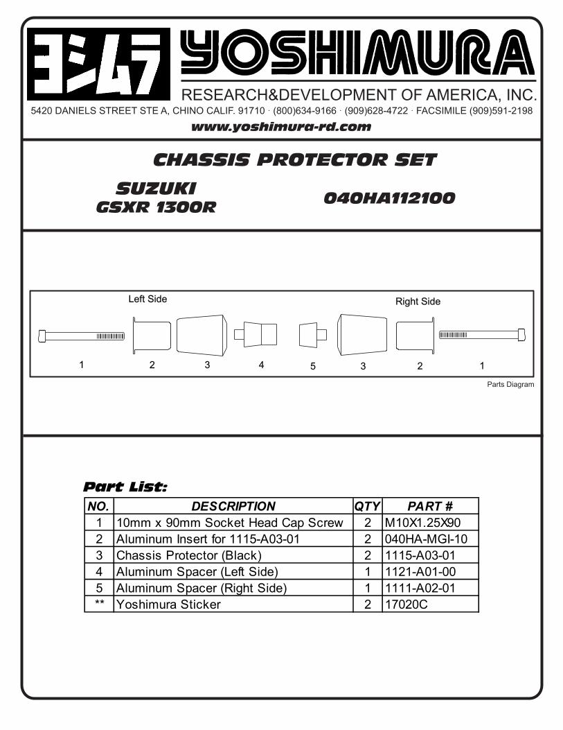
CHASSIS PROTECTOR SET
SUZUKIGSXR 1300R
5420 DANIELS STREET STE A CHINO CALIF 91710 middot (800)634-9166 middot (909)628-4722 middot FACSIMILE (909)591-2198
NO DESCRIPTION QTY PART
1 10mm x 90mm Socket Head Cap Screw 2 M10X125X90
2 Aluminum Insert for 1115-A03-01 2 040HA-MGI-10
3 Chassis Protector (Black) 2 1115-A03-01
4 Aluminum Spacer (Left Side) 1 1121-A01-00
5 Aluminum Spacer (Right Side) 1 1111-A02-01
Yoshimura Sticker 2 17020C
3
Left Side Right Side
5 2431 2 1
Parts Diagram
Part List
040HA112100
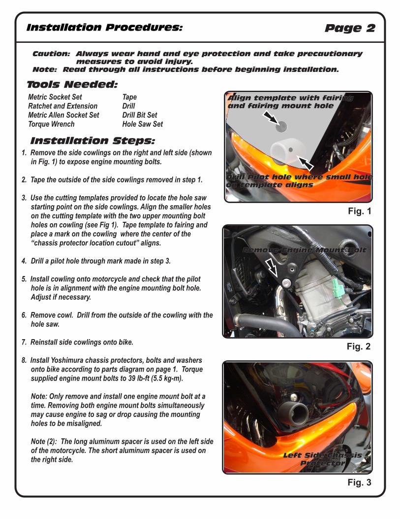
Installation Procedures Page 2
1 Remove the side cowlings on the right and left side (shown in Fig 1) to expose engine mounting bolts
2 Tape the outside of the side cowlings removed in step 1
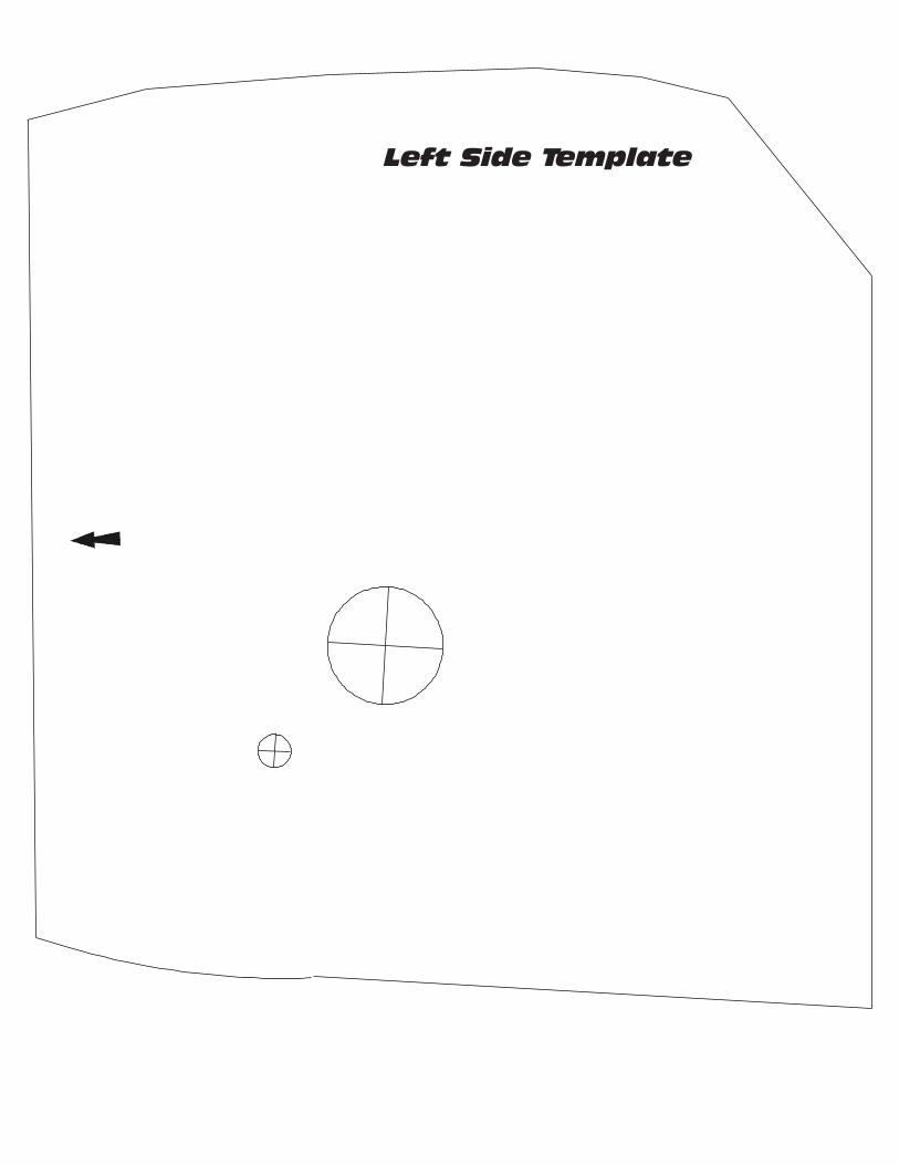
3 Use the cutting templates provided to locate the hole saw starting point on the side cowlings Align the smaller holes on the cutting template with the two upper mounting bolt holes on cowling (see Fig 1) Tape template to fairing and place a mark on the cowling where the center of the ldquochassis protector location cutoutrdquo aligns
4 Drill a pilot hole through mark made in step 3
5 Install cowling onto motorcycle and check that the pilot hole is in alignment with the engine mounting bolt hole Adjust if necessary
6 Remove cowl Drill from the outside of the cowling with the hole saw
7 Reinstall side cowlings onto bike
8 Install Yoshimura chassis protectors bolts and washers onto bike according to parts diagram on page 1 Torque supplied engine mount bolts to 39 lb-ft (55 kg-m)
Note Only remove and install one engine mount bolt at a time Removing both engine mount bolts simultaneously may cause engine to sag or drop causing the mounting holes to be misaligned
Note (2) The long aluminum spacer is used on the left side
of the motorcycle The short aluminum spacer is used on the right side
Caution Always wear hand and eye protection and take precautionary measures to avoid injury
Note Read through all instructions before beginning installation
Tools Needed
Metric Socket Set TapeRatchet and Extension Drill Metric Allen Socket Set Drill Bit SetTorque Wrench Hole Saw Set
Installation Steps
Fig 1
Fig 2
Fig 3
Align template with fairingand fairing mount hole
Remove Engine Mount Bolt
Left Side ChassisProtector
Drill Pilot hole where small holeon template aligns
Right Side Template
Left Side Template
- Page 1
- Page 2
- Page 3
- Page 4
-
Installation Procedures Page 2
1 Remove the side cowlings on the right and left side (shown in Fig 1) to expose engine mounting bolts
2 Tape the outside of the side cowlings removed in step 1
3 Use the cutting templates provided to locate the hole saw starting point on the side cowlings Align the smaller holes on the cutting template with the two upper mounting bolt holes on cowling (see Fig 1) Tape template to fairing and place a mark on the cowling where the center of the ldquochassis protector location cutoutrdquo aligns
4 Drill a pilot hole through mark made in step 3
5 Install cowling onto motorcycle and check that the pilot hole is in alignment with the engine mounting bolt hole Adjust if necessary
6 Remove cowl Drill from the outside of the cowling with the hole saw
7 Reinstall side cowlings onto bike
8 Install Yoshimura chassis protectors bolts and washers onto bike according to parts diagram on page 1 Torque supplied engine mount bolts to 39 lb-ft (55 kg-m)
Note Only remove and install one engine mount bolt at a time Removing both engine mount bolts simultaneously may cause engine to sag or drop causing the mounting holes to be misaligned
Note (2) The long aluminum spacer is used on the left side
of the motorcycle The short aluminum spacer is used on the right side
Caution Always wear hand and eye protection and take precautionary measures to avoid injury
Note Read through all instructions before beginning installation
Tools Needed
Metric Socket Set TapeRatchet and Extension Drill Metric Allen Socket Set Drill Bit SetTorque Wrench Hole Saw Set
Installation Steps
Fig 1
Fig 2
Fig 3
Align template with fairingand fairing mount hole
Remove Engine Mount Bolt
Left Side ChassisProtector
Drill Pilot hole where small holeon template aligns
Right Side Template
Left Side Template
- Page 1
- Page 2
- Page 3
- Page 4
-

Right Side Template
Left Side Template
- Page 1
- Page 2
- Page 3
- Page 4
-
Left Side Template
- Page 1
- Page 2
- Page 3
- Page 4
-