chassis design
TRANSCRIPT
i
DESIGN AND ANALYSIS OF CAR CHASSIS
MOHAMAD SAZUAN BIN SARIFUDIN
A report submitted for partial fulfilment of the requirement for the
Diploma of Mechanical Engineering award.
Faculty of Mechanical Engineering
UNIVERSITI MALAYSIA PAHANG
JANUARY 2012
vi
ABSTRACT
This project concerns on the assessment on making an analysis of the car
chassis will fit all aspects and concepts according to the rules of Eco Marathon
Challenge. The objective of this project to design and analyse of car chassis. To
avoid any possibilities of failure of the structure and thus to provide enough
supporting member to make the region stronger in term of deformation. Finite
element analysis enables to predict the region that tends to fail due to loading.
Besides that, need to utilize the feature of CAE software named as FEMPRO to get
the distribution of stress and strain on the chassis, both component as well as the
material costing. The main objective is to study the effect of load that applied in term
of driver weight, the car body and the equipment.
vii
ABSTRAK
Projek ini menekankan pembelajaran berkenaan dengan cara–cara
menganalisa terhadap casis kereta berdasarkan undang-undang yang terdapat di
dalam pertandingan Shell Eco Marathon. Objektif projek ini ada untuk mebuat
rekaan adan menganalisa casis kereta. Untuk menghindarkan sebarang kemungkinan
kegagalan struktur casis kereta dan membrikan sokongan yang secukupnya kepada
casis kereta. Analisa “Finite element” membantu untuk mengesan kawasan yang
berkemungkinan akan gagal. Perisian CAE atau FEMPRO digunakan untuk
mendapatkan taburan “stress” dan “strain”. Tambahan pula, tujuan utama adalah
untuk menelaah kesan bebanan hasil daripada berat pemandu, berat body dan berat
kelengkapan tambahan.
viii
TABLE OF CONTENTS
Page
SUPERVISOR’S DECLARATION ii
STUDENT’S DECLARATION iii
DEDICATION iv
ACKNOWLEDGEMENTS v
ABSTRACT vi
ABSTRAK vii
TABLE OF CONTENTS viii
LIST OF TABLES xi
LIST OF FIGURES xii
LIST OF SYMBOLS, ABBREVIATIONS xv
AND NOMECLATURES
CHAPTER 1 INTRODUCTION
1.1 Background 1
1.2
1.3
Problem Statement
Objectives
1.2.1 General objectives1.2.2 Specific objectives
2
2
23
1.4 Scopes 3
CHAPTER 2 LITERATURE REVIEW
2.1
2.2
Introduction
Terminology
2.2.1 Strength2.2.2 Stiffness2.2.3 Vibrational behaviour2.2.4 Selection of vehicle type and concept
4
4
5567
1 × ENTER (1.5 line spacing)

ix
2.3 Type of chassis 7
2.4 Chassis design principle 10
2.5
2.6
2.7
Materials
2.5.1 Stainless steel2.5.2 Aluminium2.5.3 Iron
Material mechanical concept
Finite element analysis using Algor
12
121416
17
19
CHAPTER 3 METHODOLOGY
3.1 Introduction 20
3.2 Design method
3.2.1 Evaluating3.2.2 Conceptual design3.2.3 Preliminary design3.2.4 Chassis design analysis using ALGOR3.2.5 Develop prototype
21
2124262630
CHAPTER 4 RESULT AND DISCUSSION
4.1 Introduction 34
4.2
4.3
4.4
Finite element analysis (FEA) on chassis using ALGOR
Simulation Results Using Algor Software
4.3.1 Aluminium4.3.2 Stainless steel4.3.3 Iron
Discussion
4.4.1 Comparison results of chassis
34
35
354147
53
53
CHAPTER 5 CONCLUSION AND RECOMMENDATION
5.1 Conclusion 55
5.2 Recommendations 56

x
REFERENCES 57
APPENDICES 59
xi
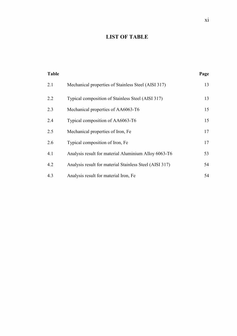
LIST OF TABLE
Table Page
2.1 Mechanical properties of Stainless Steel (AISI 317) 13
2.2 Typical composition of Stainless Steel (AISI 317) 13
2.3 Mechanical properties of AA6063-T6 15
2.4 Typical composition of AA6063-T6 15
2.5 Mechanical properties of Iron, Fe 17
2.6
4.1
Typical composition of Iron, Fe
Analysis result for material Aluminium Alloy 6063-T6
17
53
4.2 Analysis result for material Stainless Steel (AISI 317) 54
4.3 Analysis result for material Iron, Fe 54
xii
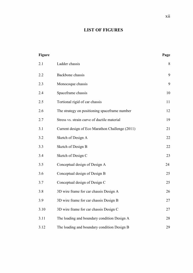
LIST OF FIGURES
Figure Page
2.1 Ladder chassis 8
2.2 Backbone chassis 9
2.3 Monocoque chassis 9
2.4 Spaceframe chassis 10
2.5 Tortional rigid of car chassis 11
2.6
2.7
The strategy on positioning spaceframe number
Stress vs. strain curve of ductile material
12
19
3.1 Current design of Eco Marathon Challenge (2011) 21
3.2 Sketch of Design A 22
3.3 Sketch of Design B 22
3.4 Sketch of Design C 23
3.5 Conceptual design of Design A 24
3.6
3.7
3.8
3.9
3.10
3.11
3.12
Conceptual design of Design B
Conceptual design of Design C
3D wire frame for car chassis Design A
3D wire frame for car chassis Design B
3D wire frame for car chassis Design C
The loading and boundary condition Design A
The loading and boundary condition Design B
25
25
26
27
27
28
29
xiii
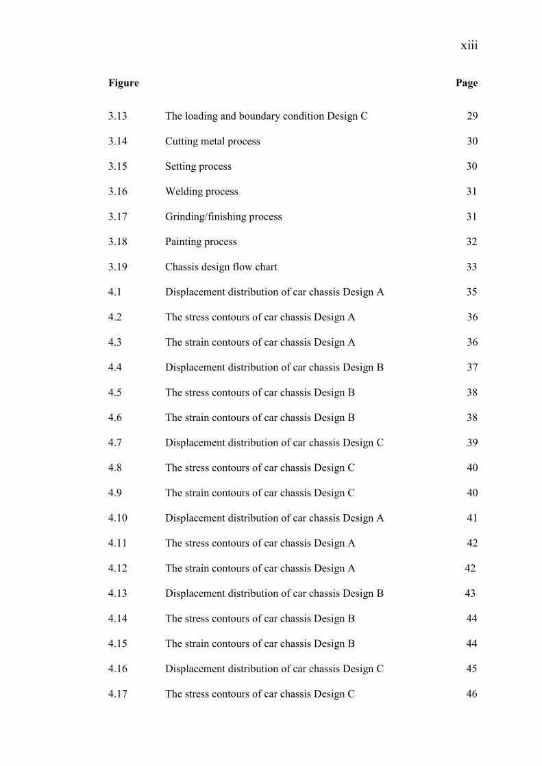
Figure Page
3.13
3.14
3.15
3.16
3.17
3.18
3.19
4.1
The loading and boundary condition Design C
Cutting metal process
Setting process
Welding process
Grinding/finishing process
Painting process
Chassis design flow chart
Displacement distribution of car chassis Design A
29
30
30
31
31
32
33
35
4.2 The stress contours of car chassis Design A 36
4.3 The strain contours of car chassis Design A 36
4.4 Displacement distribution of car chassis Design B 37
4.5 The stress contours of car chassis Design B 38
4.6 The strain contours of car chassis Design B 38
4.7 Displacement distribution of car chassis Design C 39
4.8 The stress contours of car chassis Design C 40
4.9 The strain contours of car chassis Design C 40
4.10 Displacement distribution of car chassis Design A 41
4.11 The stress contours of car chassis Design A 42
4.12 The strain contours of car chassis Design A 42
4.13
4.14
4.15
4.16
4.17
Displacement distribution of car chassis Design B
The stress contours of car chassis Design B
The strain contours of car chassis Design B
Displacement distribution of car chassis Design C
The stress contours of car chassis Design C
43
44
44
45
46
xiv
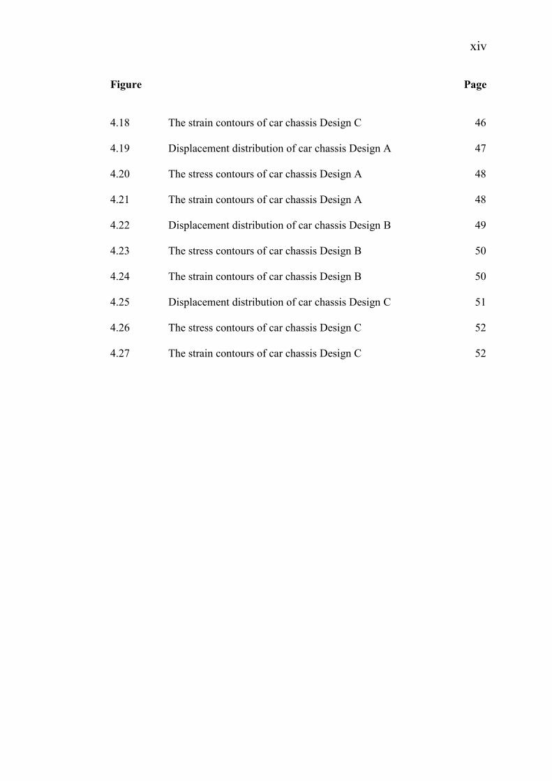
Figure
4.18
4.19
4.20
4.21
4.22
4.23
4.24
4.25
4.26
4.27
The strain contours of car chassis Design C
Displacement distribution of car chassis Design A
The stress contours of car chassis Design A
The strain contours of car chassis Design A
Displacement distribution of car chassis Design B
The stress contours of car chassis Design B
The strain contours of car chassis Design B
Displacement distribution of car chassis Design C
The stress contours of car chassis Design C
The strain contours of car chassis Design C
Page
46
47
48
48
49
50
50
51
52
52
xv
LIST OF SYMBOLS, ABBREVIATIONS AND NOMENCLATURE
σ True Stress, Local Stress
δ Displacement Magnitude
ε True Strain, Local Strain
% Percent
KB, Bending Stiffness
KT
°C
Torsion Stiffness
Degree Celsius
°F Degree Fahrenheit
Cr
Fe
Mg
Mn
Si
Ti
Cu
Al
Zn
C
S
CAE
FEA
Chromium
Iron
Magnesium
Manganese
Silicon
Titanium
Copper
Aluminium
Zinc
Carbon
Sulphur
Angle
Computer-aided Engineering
Finite Element Analysis
xvi
FYP
UMP
AA
SUV
USA
3D
Final Year Project
Universiti Malaysia Pahang
Aluminium Alloy
Sport Utility Vehicle
United States of America
Three-dimensional
CHAPTER 1
INTRODUCTION
1.1 BACKGROUND
Many types of pollution such as water pollution, noise pollution, thermal
pollution and air pollution. Air pollution can be considered as one of the main hazard
to the health of human being. The air pollution is due to the increasing number of
vehicle use by human. When the number of vehicle increase, the usage of the petrol
increase respectively. The lack of the source of the petrol makes the price increase by
time to time. The emission from the vehicle makes the environment faces the air
pollution that in critical level.
Many steps need to reduce the number of the vehicle in other side to reduce
the price of the petrol. Besides that also use to reduce the air pollution. The big
number of vehicles in each country makes the prevention to reduce the number of
vehicle difficult. So, the other prevention is increase the efficiency of the vehicle’s
engine. When the engine at the efficient level, the emission is at the low level and the
most important is the usage of petrol is low. The prevention is reducing the weight of
the body and chassis of each vehicle.
This project focused to reduce the usage of petrol by design and analysis the
chassis to reduce the weight of the chassis of vehicle. At the same time, the global
usage of the petrol also reduced.
2
1.1 PROBLEM STATEMENT
Nowadays, the usage of transport increasing day to day on the road. The
number increase due to those people that usually choose to use own vehicle than
public transport. When the vehicle number increase, the price of petrol (fuel) also
increase. At the same time, the emissions from the vehicles increase the air pollution.
The prevention steps need to reduce the number of car and price of petrol. Cars
emitted high emission and use high amount of petrol when the cars have bigger
weight. Preventive step by reducing the weight of the body and chassis can reduce
the usage of petrol.
1.2 OBJECTIVES
1.2.1 General Objectives
The objective of this project is to expose to the student on the process of
design and analysis of a product. In addition, student also able to apply their
knowledge and their skill that have learnt during class and outside class. Besides,
student also can add their knowledge by make this project. The project challenge the
student to do research and solving any problem that will be appeared towards a
successful project.
Student able to practice his own soft skill on how to communicate well wit
person to person by the presentation section. Besides, it can train student’s capability
in answering, questioning, researching, evaluating, data gathering, decision making,
planning and problem solving by the research during this project.
From this project, student able to make a good research in technical writing.
Furthermore, this project can encourage the student how to be more independent in
searching, detailing, and expanding their knowledge and also have own experience
under minimal supervisory.
3
1.2.2 Specific Objectives
The main objectives of this project are as follows:
i. To evaluate current chassis
ii. To redesign car chassis
iii. To analyze in term of structure failure using Algor software
1.3 SCOPES
i. This car is designed for Shell Eco Marathon Challenge (Asia) for 2012 in
prototype category.
ii. Design stage for this project using Solidworks software.
iii. Algor software is used to analyze the stress at the car chassis.
CHAPTER 2
LITERATURE REVIEW
2.1 INTRODUCTION
Basically chassis is considered as a framework to support the body, engine
and other parts which make up the vehicle. Chassis lends the whole vehicle support
and rigidity. Chassis usually includes a pair of longitudinally extending channels and
multiple transverse cross members that intersect the channels. The transverse
members have a reduced cross section in order to allow for a longitudinally
extending storage space. The chassis has to contain the various components required
for the race car as well as being based around a driver’s cockpit. The safety of the
chassis is a major aspect in the design, and should be considered through all stages.
Generally, the basic chassis types consist of backbone, ladder, spaceframe and
monocoque. Different types of chassis design result the different performance.
2.2 Terminology
The propose of car chassis is to maintain the shape of the vehicle and to
support the various loads applied to it. The structure usually accounts for a large
proportion of the development and manufacturing cost in new vehicle programme
and many different structural concepts are available to the designer. It is essential
that the best one is chosen to ensure acceptable structural performance within other
design constraints such as cost, volume and method of production, product
application and many more. Assessments of the performance of a vehicle structure
are related to its strength and stiffness. A design aim is to achieve sufficient levels of
these with as little mass as possible. (Jason, 2002)

5
2.2.1 Strength
The strength requirement implies that no part of the shape will lose its
function when it is subjected to road loads. Loss of function may be caused by
instantaneous overloads due to extreme load cases, or by material fatigue.
Instantaneous failure may be caused by either overstressing of components beyond
the elastic limit, or by buckling of items in compression or shear stress, or by failure
of the joints.
The life to initiation of fatigue cracks is highly dependent on design detail,
and can only be assessed when a detailed knowledge of the component is available.
For this reason assessment of fatigue strength is usually deferred until after the
conceptual design stage.
The strength may be alternatively defined as the maximum force which the
structure can withstand. Different load cases different local component loads, but the
structure must have sufficient strength for all load cases. (Jason, 2002)
2.2.2 Stiffness
The stiffness of the structure relates the deflection produced when load is
applied. It applies only to structures in the elastic range and is the slope of the load
versus deflection graph.
The stiffness of a vehicle structure has important influence on its handling
and vibrational behaviour. It is important to ensure that deflection due to extreme
loads is not so large to impair the function of the vehicle, for an example so that the
doors will not close, or suspension geometry is altered. Low stiffness are lead to
unacceptable vibrations, such as ‘scuttle shake’. (Jason, 2002)

6
Again different load cases require different stiffness definitions, and some of
these are often used as ‘benchmarks’ of vehicle structural performance. The two
most commonly used in this way are (Jason, 2002):
a) Bending stiffness KB, which relates the symmetrical vertical deflection of a
point near the centre of the wheelbase to multiples of the total static loads on
the vehicle. A simplified version of this to relate the deflection to a single,
symmetrically applied load near the centre of the wheelbase.
b) Torsion stiffness KT, relates the torsional deflection of the structure to an
applied pure torque T about the longitudinal axis of the vehicle. The vehicle
is subjected to the ‘pure torsion load case’. Twist angle is measured between
the front and rear suspension mountings. Twist are intermediate points along
the wheelbase is sometimes also measured in order to highlight regions of the
structure needing stiffening.
The two cases apply completely different local loads to individual
components within the vehicle. It is usually found that the torsion case is the most
difficult to design for, so that the torsion stiffness is often used as a benchmark to
indicate the effectiveness of the vehicle structure. (Jason, 2002)
2.2.3 Vibrational behaviour
The global vibritional characteristics of a vehicle are related to both its
stiffness and mass distribution. The frequencies of the global bending and torsional
vibration modes are commonly used as benchmarks for vehicle structural
performance. These are not discussed in this book. However, bending and torsion
stiffness KB and KT influence the vibrational behaviour of the structure, particularly
its first natural frequency. (Jason, 2002)
7
2.2.4 Selection of vehicle type and concept
In order to achieve a satisfactory structure, the following must be selected (Jason,
2002):
a) The most appropriate structural type for the intended application.
b) The correct layout of structural elements to ensure satisfactory load paths,
without discontinuities, through the vehicle structure.
c) Appropriate sizing of panels and sections, and good detail design of joints.
An assumption made in this book is that is satisfactory load path (i.e. if the
equilibrium of edge forces between simple structural surfaces) are achieved, then the
vehicle is likely to have the foundation for sufficient structural (and especially
torsion) stiffness. Estimate of interface loads between major body components
calculated by the simplified methods described are assumed to be sufficiently
accurate for conceptual design although the structural members comprising load
paths must still be sized appropriately for satisfactory results. Early estimates of
stiffness can be obtained using the finite element method, but the results should be
treated with caution because of simplifications in the idealization of the structure at
this stage. (Jason, 2002)
2.3 TYPE OF CHASSSIS
Chassis is considered to be one of the significant structures of an automobile.
Itis usually made of a steel frame, which holds the body and motor of an automotive
vehicle. To be precise, car chassis or automobile chassis is a skeletal frame which
bolts various mechanical parts like engine, tires, brakes, steering and axle assemblies.
Chassis usually made of light a metal or composite plastic which provides strength
needed for supporting vehicle components and load into it. Here I listed several
different types of automotive chassis which include ladder chassis, backbone chassis,
monocoque chassis and tubular space frame chassis (Wakeham, 2009).
8
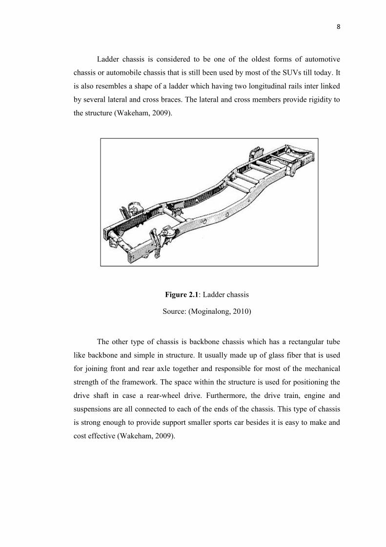
Ladder chassis is considered to be one of the oldest forms of automotive
chassis or automobile chassis that is still been used by most of the SUVs till today. It
is also resembles a shape of a ladder which having two longitudinal rails inter linked
by several lateral and cross braces. The lateral and cross members provide rigidity to
the structure (Wakeham, 2009).
Figure 2.1: Ladder chassis
Source: (Moginalong, 2010)
The other type of chassis is backbone chassis which has a rectangular tube
like backbone and simple in structure. It usually made up of glass fiber that is used
for joining front and rear axle together and responsible for most of the mechanical
strength of the framework. The space within the structure is used for positioning the
drive shaft in case a rear-wheel drive. Furthermore, the drive train, engine and
suspensions are all connected to each of the ends of the chassis. This type of chassis
is strong enough to provide support smaller sports car besides it is easy to make and
cost effective (Wakeham, 2009).
9
Figure 2.2: Backbone chassis
Source: (Which K, 2002)
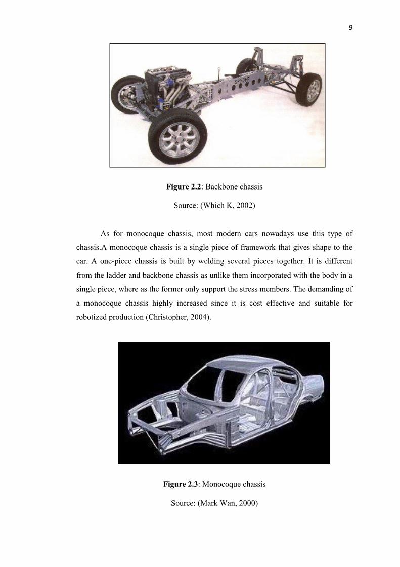
As for monocoque chassis, most modern cars nowadays use this type of
chassis.A monocoque chassis is a single piece of framework that gives shape to the
car. A one-piece chassis is built by welding several pieces together. It is different
from the ladder and backbone chassis as unlike them incorporated with the body in a
single piece, where as the former only support the stress members. The demanding of
a monocoque chassis highly increased since it is cost effective and suitable for
robotized production (Christopher, 2004).
Figure 2.3: Monocoque chassis
Source: (Mark Wan, 2000)
10
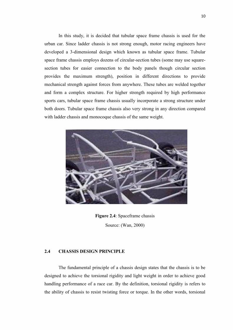
In this study, it is decided that tubular space frame chassis is used for the
urban car. Since ladder chassis is not strong enough, motor racing engineers have
developed a 3-dimensional design which known as tubular space frame. Tubular
space frame chassis employs dozens of circular-section tubes (some may use square-
section tubes for easier connection to the body panels though circular section
provides the maximum strength), position in different directions to provide
mechanical strength against forces from anywhere. These tubes are welded together
and form a complex structure. For higher strength required by high performance
sports cars, tubular space frame chassis usually incorporate a strong structure under
both doors. Tubular space frame chassis also very strong in any direction compared
with ladder chassis and monocoque chassis of the same weight.
Figure 2.4: Spaceframe chassis
Source: (Wan, 2000)
2.4 CHASSIS DESIGN PRINCIPLE
The fundamental principle of a chassis design states that the chassis is to be
designed to achieve the torsional rigidity and light weight in order to achieve good
handling performance of a race car. By the definition, torsional rigidity is refers to
the ability of chassis to resist twisting force or torque. In the other words, torsional
10
In this study, it is decided that tubular space frame chassis is used for the
urban car. Since ladder chassis is not strong enough, motor racing engineers have
developed a 3-dimensional design which known as tubular space frame. Tubular
space frame chassis employs dozens of circular-section tubes (some may use square-
section tubes for easier connection to the body panels though circular section
provides the maximum strength), position in different directions to provide
mechanical strength against forces from anywhere. These tubes are welded together
and form a complex structure. For higher strength required by high performance
sports cars, tubular space frame chassis usually incorporate a strong structure under
both doors. Tubular space frame chassis also very strong in any direction compared
with ladder chassis and monocoque chassis of the same weight.
Figure 2.4: Spaceframe chassis
Source: (Wan, 2000)
2.4 CHASSIS DESIGN PRINCIPLE
The fundamental principle of a chassis design states that the chassis is to be
designed to achieve the torsional rigidity and light weight in order to achieve good
handling performance of a race car. By the definition, torsional rigidity is refers to
the ability of chassis to resist twisting force or torque. In the other words, torsional
11
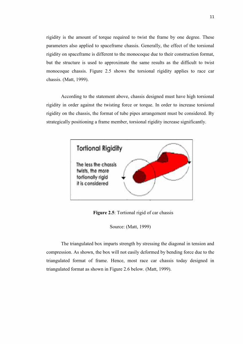
rigidity is the amount of torque required to twist the frame by one degree. These
parameters also applied to spaceframe chassis. Generally, the effect of the torsional
rigidity on spaceframe is different to the monocoque due to their construction format,
but the structure is used to approximate the same results as the difficult to twist
monocoque chassis. Figure 2.5 shows the torsional rigidity applies to race car
chassis. (Matt, 1999).
According to the statement above, chassis designed must have high torsional
rigidity in order against the twisting force or torque. In order to increase torsional
rigidity on the chassis, the format of tube pipes arrangement must be considered. By
strategically positioning a frame member, torsional rigidity increase significantly.
`
Source: (Matt, 1999)
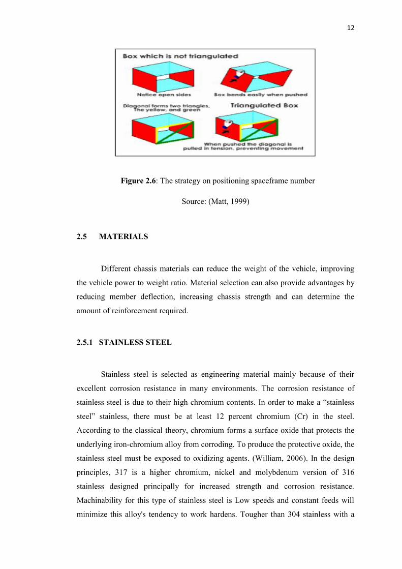
The triangulated box imparts strength by stressing the diagonal in tension and
compression. As shown, the box will not easily deformed by bending force due to the
triangulated format of frame. Hence, most race car chassis today designed in
triangulated format as shown in Figure 2.6 below. (Matt, 1999).
Figure 2.5: Tortional rigid of car chassis
11
rigidity is the amount of torque required to twist the frame by one degree. These
parameters also applied to spaceframe chassis. Generally, the effect of the torsional
rigidity on spaceframe is different to the monocoque due to their construction format,
but the structure is used to approximate the same results as the difficult to twist
monocoque chassis. Figure 2.5 shows the torsional rigidity applies to race car
chassis. (Matt, 1999).
According to the statement above, chassis designed must have high torsional
rigidity in order against the twisting force or torque. In order to increase torsional
rigidity on the chassis, the format of tube pipes arrangement must be considered. By
strategically positioning a frame member, torsional rigidity increase significantly.
`
Source: (Matt, 1999)
The triangulated box imparts strength by stressing the diagonal in tension and
compression. As shown, the box will not easily deformed by bending force due to the
triangulated format of frame. Hence, most race car chassis today designed in
triangulated format as shown in Figure 2.6 below. (Matt, 1999).
Figure 2.5: Tortional rigid of car chassis
12
Source: (Matt, 1999)
2.5 MATERIALS
Different chassis materials can reduce the weight of the vehicle, improving
the vehicle power to weight ratio. Material selection can also provide advantages by
reducing member deflection, increasing chassis strength and can determine the
amount of reinforcement required.
2.5.1 STAINLESS STEEL
Stainless steel is selected as engineering material mainly because of their
excellent corrosion resistance in many environments. The corrosion resistance of
stainless steel is due to their high chromium contents. In order to make a “stainless
steel” stainless, there must be at least 12 percent chromium (Cr) in the steel.
According to the classical theory, chromium forms a surface oxide that protects the
underlying iron-chromium alloy from corroding. To produce the protective oxide, the
stainless steel must be exposed to oxidizing agents. (William, 2006). In the design
principles, 317 is a higher chromium, nickel and molybdenum version of 316
stainless designed principally for increased strength and corrosion resistance.
Machinability for this type of stainless steel is Low speeds and constant feeds will
minimize this alloy's tendency to work hardens. Tougher than 304 stainless with a
Figure 2.6: The strategy on positioning spaceframe number
13
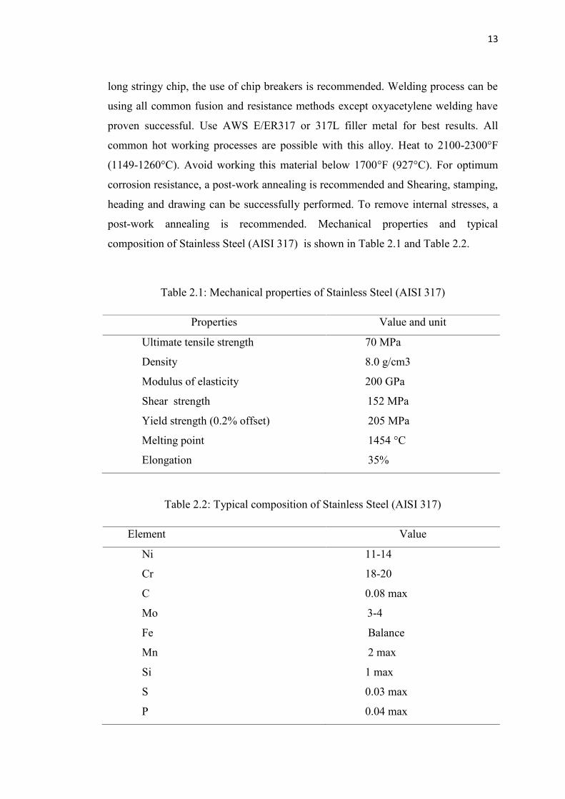
long stringy chip, the use of chip breakers is recommended. Welding process can be
using all common fusion and resistance methods except oxyacetylene welding have
proven successful. Use AWS E/ER317 or 317L filler metal for best results. All
common hot working processes are possible with this alloy. Heat to 2100-2300°F
(1149-1260°C). Avoid working this material below 1700°F (927°C). For optimum
corrosion resistance, a post-work annealing is recommended and Shearing, stamping,
heading and drawing can be successfully performed. To remove internal stresses, a
post-work annealing is recommended. Mechanical properties and typical
composition of Stainless Steel (AISI 317) is shown in Table 2.1 and Table 2.2.
Table 2.1: Mechanical properties of Stainless Steel (AISI 317)
Properties Value and unit
Ultimate tensile strength
Density
Modulus of elasticity
Shear strength
Yield strength (0.2% offset)
Melting point
Elongation
70 MPa
8.0 g/cm3
200 GPa
152 MPa
205 MPa
1454 °C
35%
Table 2.2: Typical composition of Stainless Steel (AISI 317)
Element Value
Ni
Cr
C
Mo
Fe
Mn
Si
S
P
11-14
18-20
0.08 max
3-4
Balance
2 max
1 max
0.03 max
0.04 max
14
2.5.2 ALUMINIUM
Aluminium is a nonferrous material with very high corrosion resistance and
very light material compared to steels. Aluminium cannot match the strength of steel
but its strength-to-weight ratio can make it competitive in certain stress application.
Aluminium can also be alloyed and heat treated to improve it mechanical properties,
which then makes it much more competitive with steels however the cost increases
dramatically. Pure aluminium is also a possible material and is reasonably affordable
and very light but it is the weakest and requires extra reinforcement to produce a
rigid chassis. Aluminium is very hard to work with as it requires very skilled welding
and is an overall softer metal. Basically there are several types of aluminium. For this
project, decide to test with Aluminium Alloy 6063-T6. Aluminium alloy 6063 is one
of the most extensively used of the 6000 series aluminium alloys.
Aluminium Alloy 6063 is the least expensive and most versatile of the heat
treatable aluminium alloys. It has most of the good qualities of aluminium. It offers a
range of good mechanical properties and good corrosion resistance. It can be
fabricated by most of the commonly used techniques. In the annealed condition it has
good workability. The typical properties of aluminium alloy 6063 include medium to
high strength, good toughness, good surface finishing, excellent corrosion resistance
to atmospheric conditions, good workability and widely available. It is welded by all
methods and can be furnace brazed. It is available in the clad form ("Alclad") with a
thin surface layer of high purity aluminum to improve both appearance and corrosion
resistance. This aluminum type is used for a wide variety of products and
applications from truck bodies and frames to screw machine parts and structural
components. 6063 is used where appearance and better corrosion resistance with
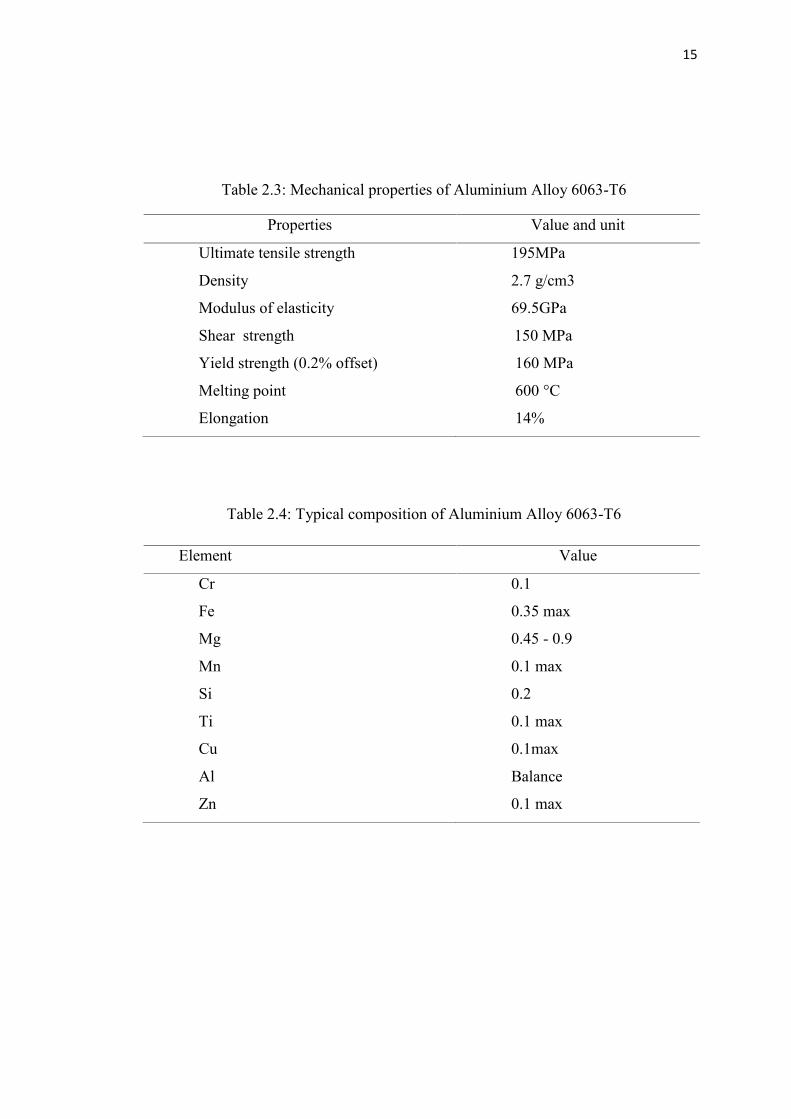
good strength are required. Mechanical properties and typical composition of
Aluminium Alloy 6063-T6 is shown in Table 2.3 and Table 2.4.
15
Table 2.3: Mechanical properties of Aluminium Alloy 6063-T6
Properties Value and unit
Ultimate tensile strength
Density
Modulus of elasticity
Shear strength
Yield strength (0.2% offset)
Melting point
Elongation
195MPa
2.7 g/cm3
69.5GPa
150 MPa
160 MPa
600 °C
14%
Table 2.4: Typical composition of Aluminium Alloy 6063-T6
Element Value
Cr
Fe
Mg
Mn
Si
Ti
Cu
Al
Zn
0.1
0.35 max
0.45 - 0.9
0.1 max
0.2
0.1 max
0.1max
Balance
0.1 max
16
2.5.3 IRON
Iron is a lustrous, ductile, malleable, silver-gray metal (group VIII of
the periodic table). It is known to exist in four distinct crystalline forms. Iron rusts in
dump air, but not in dry air. It dissolves readily in dilute acids. Iron is chemically
active and forms two major series of chemical compounds, the bivalent iron (II), or
ferrous, compounds and the trivalent iron (III), or ferric, compounds. Iron is the most
used of all the metals, including 95 % of all the metal tonnage produced worldwide.
Thanks to the combination of low cost and high strength it is indispensable. Its
applications go from food containers to family cars, from screwdrivers to washing
machines, from cargo ships to paper staples.
Steel is the best known alloy of iron, and some of the forms that iron takes
include: pig iron, cast iron, and carbon steel, and wrought iron, alloy steels, iron
oxides. Iron is believed to be the tenth most abundant element in the universe. Iron is
also the most abundant (by mass, 34.6%) element making up the Earth; the
concentration of iron in the various layers of the Earth ranges from high at the inner
core to about 5% in the outer crust. Most of this iron is found in various iron oxides,
such as the minerals hematite, magnetite, and taconite.
The earth's core is believed to consist largely of a metallic iron-nickel
alloy. Iron is essential to almost living things, from micro-organisms to humans.
World production of new iron is over 500 million tonnes a year, and recycled iron
adds other 300 million tonnes. Economically workable reserves of iron ores exceed
100 billion tonnes. The main mining areas are China, Brazil, Australia, Russia and
Ukraine, with sizeable amounts mined in the USA, Canada, Venezuela, Sweden and
India. Mechanical properties and typical composition of Iron (Fe) is shown in Table
2.3 and Table 2.4.
17
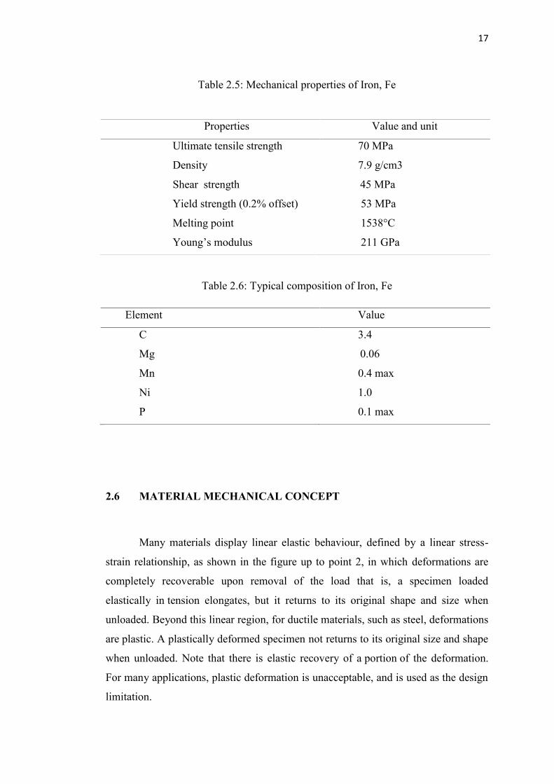
Table 2.5: Mechanical properties of Iron, Fe
Table 2.6: Typical composition of Iron, Fe
Element Value
C
Mg
Mn
Ni
P
3.4
0.06
0.4 max
1.0
0.1 max
2.6 MATERIAL MECHANICAL CONCEPT
Many materials display linear elastic behaviour, defined by a linear stress-
strain relationship, as shown in the figure up to point 2, in which deformations are
completely recoverable upon removal of the load that is, a specimen loaded
elastically in tension elongates, but it returns to its original shape and size when
unloaded. Beyond this linear region, for ductile materials, such as steel, deformations
are plastic. A plastically deformed specimen not returns to its original size and shape
when unloaded. Note that there is elastic recovery of a portion of the deformation.
For many applications, plastic deformation is unacceptable, and is used as the design
limitation.
Properties Value and unit
Ultimate tensile strength
Density
Shear strength
Yield strength (0.2% offset)
Melting point
Young’s modulus
70 MPa
7.9 g/cm3
45 MPa
53 MPa
1538°C
211 GPa
18
After the yield point, ductile metals undergo a period of strain hardening, in
which the stress increases again with increasing strain, and they begin to neck, as the
cross-sectional area of the specimen decreases due to plastic flow. In a sufficiently
ductile material, when necking becomes substantial, it causes a reversal of the
engineering stress-strain curve (curve A); this is because the engineering stress is
calculated assuming the original cross-sectional area before necking. The reversal
point is the maximum stress on the engineering stress-strain curve, and the
engineering stress coordinate of this point is the tensile ultimate strength, given by
point 1. The ultimate tensile strength is not used in the design of
ductile static members because design practices dictate the use of the yield stress. It
is, however, used for quality control, because of the ease of testing. It is also used to
roughly determine material types for unknown samples.
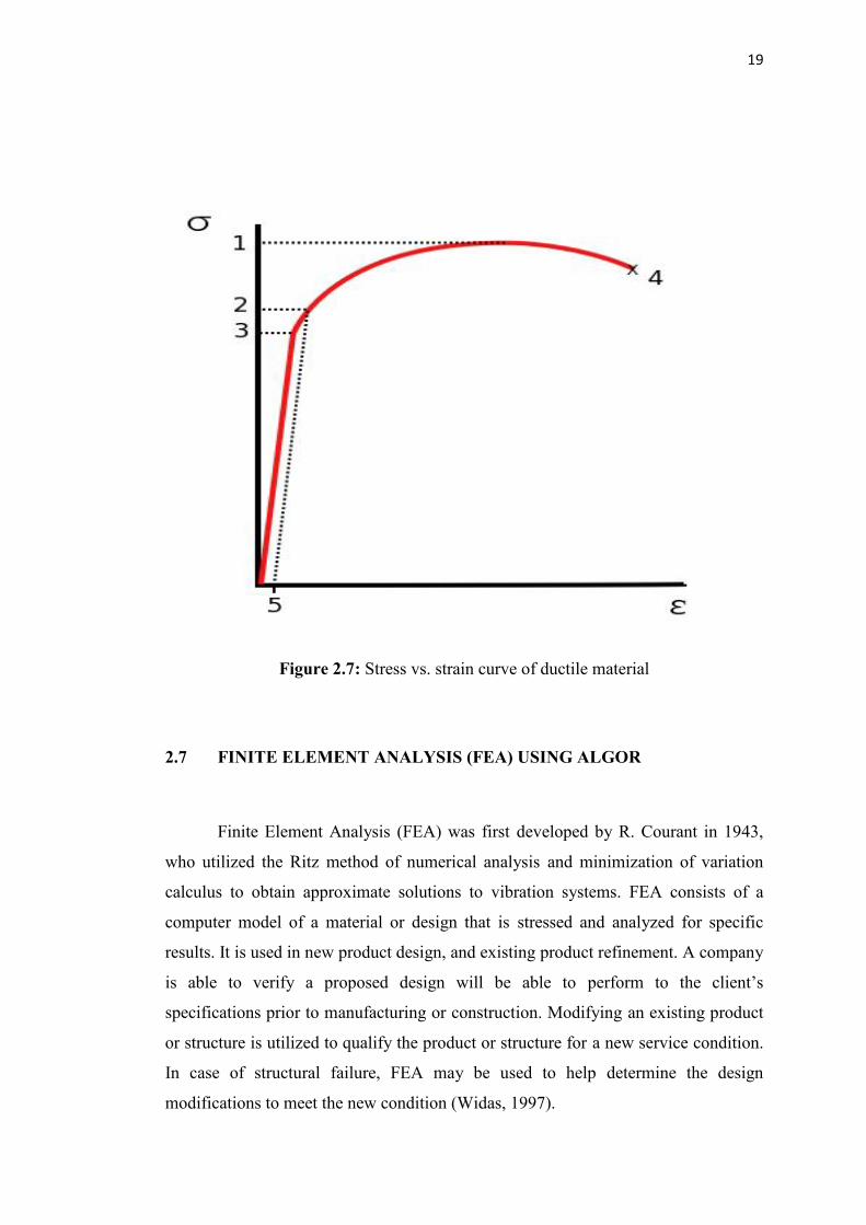
In Figure 2.7 shows the stress vs. strain curve of a ductile material, at point
number one (1) is the ultimate tensile strength, refer to the maximum stress that a
material can withstand while being stretched or pulled before necking, which is when
the specimen's cross section starts to significantly contract. At point number two (2)
is yield strength, explained that the boundary between elastic region and plastic
region. At the point number three (3) is point for the proportional limit stress, at this
point explained that the amount of stress increasing proportional to the increasing of
strain. Fracture occurred at the point number four (4). Fracture is the local separation
of an object or material into two, or more, pieces under the action of stress. Lastly at
point number five (5) is the offset strain (typically 0.2), this offset use in order to find
the yield strength of material.
19
Figure 2.7: Stress vs. strain curve of ductile material
2.7 FINITE ELEMENT ANALYSIS (FEA) USING ALGOR
Finite Element Analysis (FEA) was first developed by R. Courant in 1943,
who utilized the Ritz method of numerical analysis and minimization of variation
calculus to obtain approximate solutions to vibration systems. FEA consists of a
computer model of a material or design that is stressed and analyzed for specific
results. It is used in new product design, and existing product refinement. A company
is able to verify a proposed design will be able to perform to the client’s
specifications prior to manufacturing or construction. Modifying an existing product
or structure is utilized to qualify the product or structure for a new service condition.
In case of structural failure, FEA may be used to help determine the design
modifications to meet the new condition (Widas, 1997).
CHAPTER 3
METHODOLOGY
3.1 INTRODUCTION
Methodology can properly refer to the theoretical analysis of the methods
appropriate to the field of study or to the body of methods and also principles
particular to the branch of knowledge. In this sense, one may speak of objections to
the methodology of a geographic survey (that is, objections dealing with the
appropriateness of the methods used) or of the methodology of modern cognitive
psychology (the principles and practices that underlie research in the field).
Spaceframe more rigid to other chassis type, this is the reason race car
usually use spaceframe chassis. The chassis not absolutely just a spaceframe chassis,
but the combination between the monocoque and also the spaceframe chassis. As the
result, driver and engine compartment, the combination reduces the weight of the car.
Theoretically, the chassis design concept state that the chassis designed must
have the triangulated format of tubular pipes in order to increase the torsional rigidity
of the chassis. But for the designing of the prototype car using spaceframe chassis for
car, it is not important to follow this concept because the goals of the design is to
have a lightweight car which can cruise further by using less amount of energy. It’s
mean that, the car will not go faster and not facing the twisting force or torque. The
designer will ignore about the principle which is to place the frame members in a
triangulated format as mentioned before.
21
3.2 THE DESIGN PROCESS
The engineering design process is the steps of chassis design construction
process . In this chapter explain how chassis was designed and how stimulation of
the chassis was performed. In this part, explained how chassis is performed. Before
the last chassis design got, there are several steps must be considered to make the last
result bring the best design. In this part, start from the sketching process, the n use
SOLIDWORKS 2008 is used in order to create the model of the chassis. The analysis
stage used ALGOR 23.1 to analyze the, model of chassis.
3.2.1 EVALUATING
Before start the projects, rough ideas and the steps proposed must be drafted
to ensure the project within the planned steps. Evaluation process is important to
ensure that the design needed have advantages guided from the current design. The
ideas or steps can be gained from the evaluation of the current design (2011). The
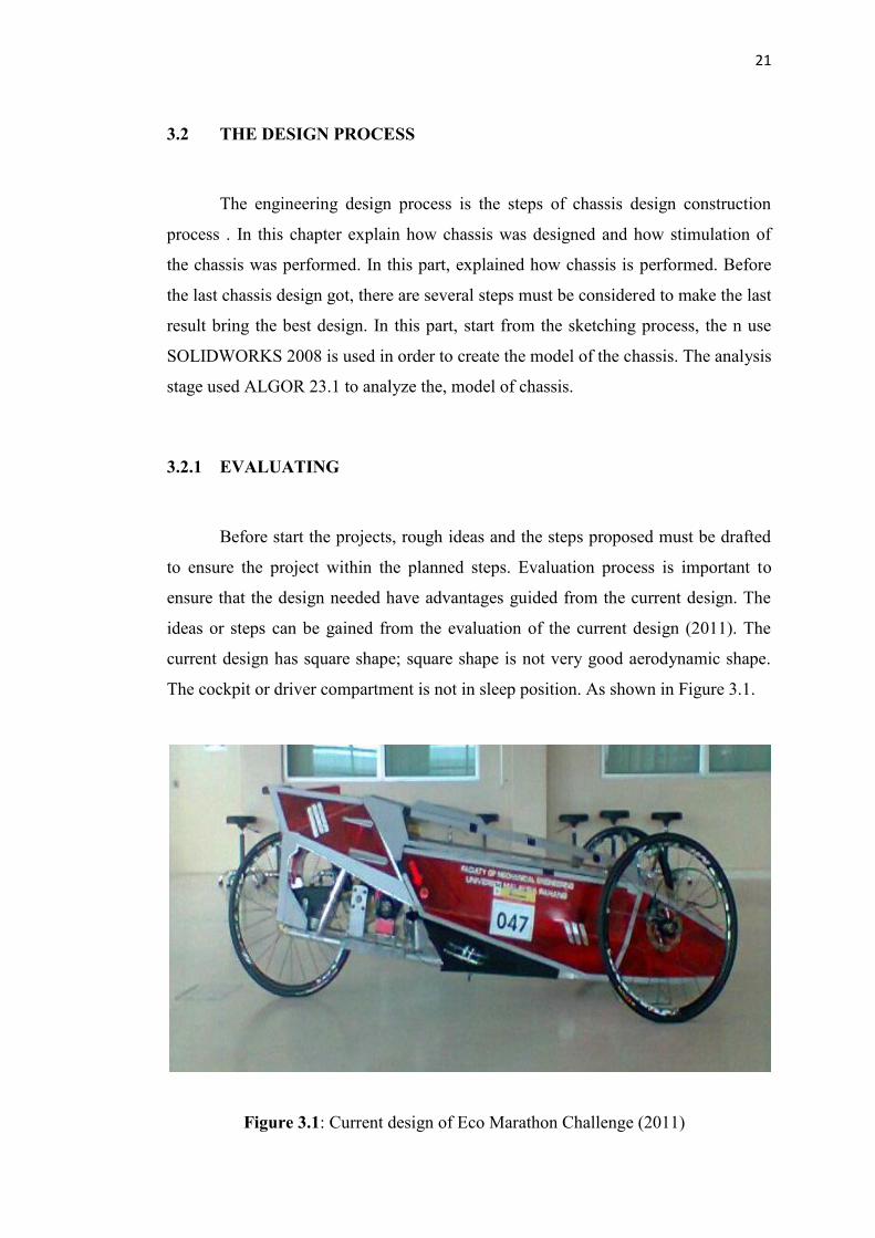
current design has square shape; square shape is not very good aerodynamic shape.
The cockpit or driver compartment is not in sleep position. As shown in Figure 3.1.
Figure 3.1: Current design of Eco Marathon Challenge (2011)
22
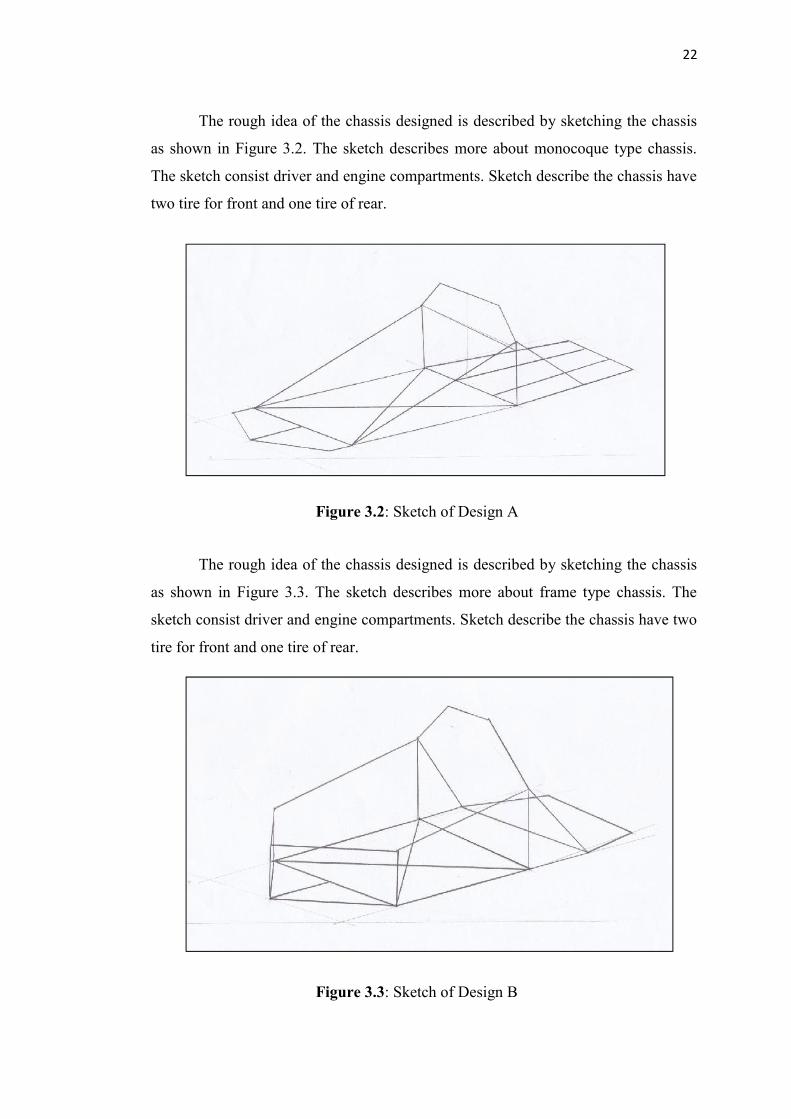
The rough idea of the chassis designed is described by sketching the chassis
as shown in Figure 3.2. The sketch describes more about monocoque type chassis.
The sketch consist driver and engine compartments. Sketch describe the chassis have
two tire for front and one tire of rear.
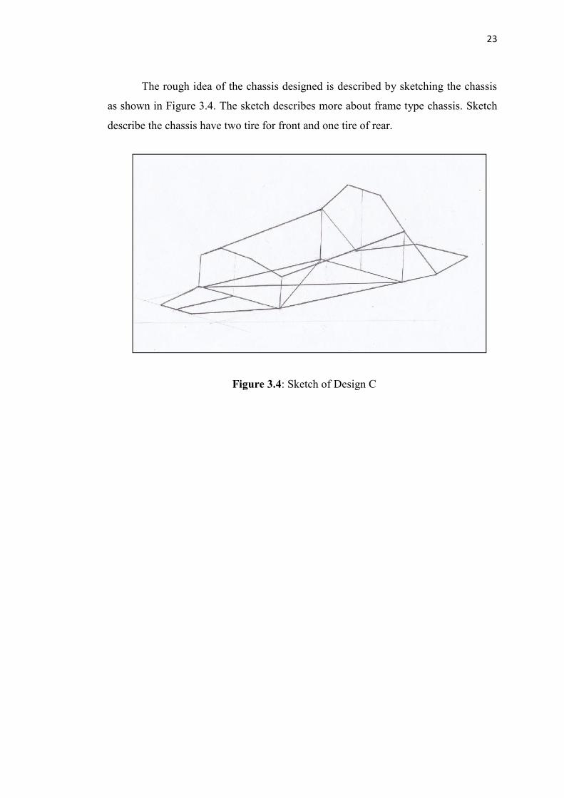
The rough idea of the chassis designed is described by sketching the chassis
as shown in Figure 3.3. The sketch describes more about frame type chassis. The
sketch consist driver and engine compartments. Sketch describe the chassis have two
tire for front and one tire of rear.
Figure 3.3: Sketch of Design B
Figure 3.2: Sketch of Design A
23
The rough idea of the chassis designed is described by sketching the chassis
as shown in Figure 3.4. The sketch describes more about frame type chassis. Sketch
describe the chassis have two tire for front and one tire of rear.
Figure 3.4: Sketch of Design C
24
3.2.2 CONCEPTUAL DESIGN
By using previous sketches in Figure 3.2, Figure 3.3, and Figure 3.4 as a
guideline, the conceptual chassis design can be using SOLIDWORKS 2008. In this
step, the best dimensions need to make the design to be draw symmetry and have
logic concept. Shown in Figure 3.5, Figure 3.6 and Figure 3.7.
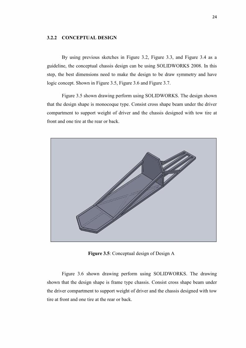
Figure 3.5 shown drawing perform using SOLIDWORKS. The design shown
that the design shape is monocoque type. Consist cross shape beam under the driver
compartment to support weight of driver and the chassis designed with tow tire at
front and one tire at the rear or back.
Figure 3.6 shown drawing perform using SOLIDWORKS. The drawing
shown that the design shape is frame type chassis. Consist cross shape beam under
the driver compartment to support weight of driver and the chassis designed with tow
tire at front and one tire at the rear or back.
Figure 3.5: Conceptual design of Design A
24
3.2.2 CONCEPTUAL DESIGN
By using previous sketches in Figure 3.2, Figure 3.3, and Figure 3.4 as a
guideline, the conceptual chassis design can be using SOLIDWORKS 2008. In this
step, the best dimensions need to make the design to be draw symmetry and have
logic concept. Shown in Figure 3.5, Figure 3.6 and Figure 3.7.
Figure 3.5 shown drawing perform using SOLIDWORKS. The design shown
that the design shape is monocoque type. Consist cross shape beam under the driver
compartment to support weight of driver and the chassis designed with tow tire at
front and one tire at the rear or back.
Figure 3.6 shown drawing perform using SOLIDWORKS. The drawing
shown that the design shape is frame type chassis. Consist cross shape beam under
the driver compartment to support weight of driver and the chassis designed with tow
tire at front and one tire at the rear or back.
Figure 3.5: Conceptual design of Design A