characterization of boron carbide for inertial confinement ... · pdf filecharacterization of...
TRANSCRIPT

Characterization of Boron Carbide for Inertial Confinement Fusion
Carolina Mattsson Lehigh University
Aug 14th, 2013
Funding provided by the NUF program & General Atomics IRD

Greg Randall [email protected]
Inertial Confinement Fusion requires lightweight ablator materials
• Low atomic numbers • Robust for fabrication • Uniformity • ~100um thick
Boron carbide also offers • Exceptional Strength • High Neutron Absorption • Non-reactivity
Ablation
Boron carbide
Radiation
Fuel

Greg Randall [email protected]
There are various ways to fabricate boron carbide
Hot-Pressing
Chemical Vapor Deposition
Sputtering
~1800˚C, ~50 MPa
B
C
B4C target
V Ar plasma
B4C coating on substrate B4C coating on substrate
Plasma with Gas phase reactants
~200-700˚C ~500˚C
Can buy from Goodfellow This study Coming soon

Greg Randall [email protected]
Sputter coating is one method of depositing films
B and C Atoms Adhere to Substrate
Argon Gas
Electric Field
Ar+ ions in Plasma
Atoms Knocked Off Surface With High KE
1-2 μm/hr

Greg Randall [email protected]
My project has been to fabricate and characterize boron carbide films
Goal is to obtain dense and uniformly textured ~100μm films
Analyze films made with various parameters
Refine coating parameters
Fabricate boron carbide films
- Thickness - Size - Density - Roughness - Crystallinity (XRD) - Stoichiometry - Microstructure - Toughness - Stress
Develop characterization techniques

Greg Randall [email protected]
Microstructure and stress are interrelated and the most important properties to control
Stress Microstructure
Lower Ar Pressure St
ress
Zone 1 Zone T
Windischmann, 1991
Density
ten
sile
c
om
pre
ssiv
e
Greg Randall [email protected]
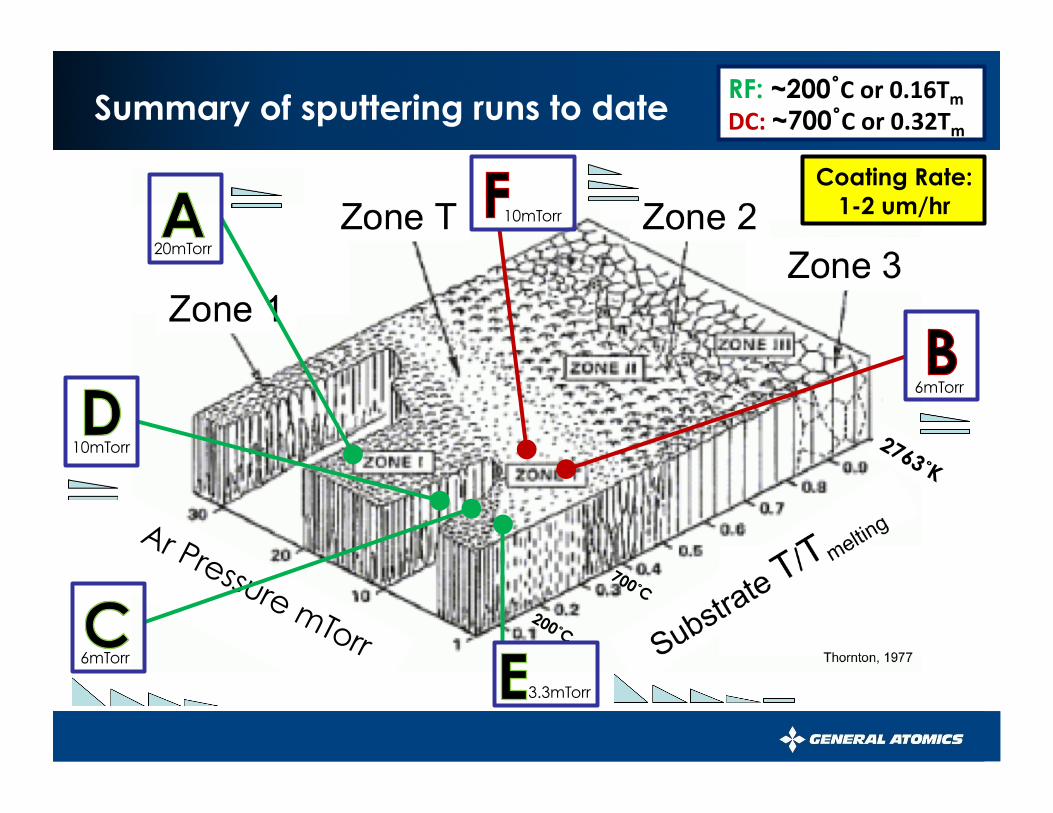
Summary of sputtering runs to date RF: ~200˚C or 0.16Tm DC: ~700˚C or 0.32Tm
20mTorr
10mTorr
6mTorr
3.3mTorr
10mTorr
6mTorr
Coating Rate: 1-2 um/hr

Greg Randall [email protected]
We see lessening of columnar structure with lower pressure, except with DC and extreme angles
RF DC
Crystalline?
Lower pressures and angles are generally more uniform, which is preferred
20mTorr
10mTorr
6mTorr
3.3mTorr
10mTorr
10mTorr zoomed out
6mTorr

Greg Randall [email protected]
Properties
Surface roughness -- Wyko Density - Microbalance, ImageJ, Dual Confocal
15.2 mm2
Ideal ** 2.52 g/cm3
Hot Pressed 2.45
Average RF sputter
2.38 ±0.05
Average DC sputter Slightly higher? Ra: 7.70nm
Crystalline Structure -- XRD
1000
800
600
400
200
080604020
1000
800
600
400
200
080604020
1000
800
600
400
200
080604020
1000
800
600
400
200
080604020
Xra
y D
iffra
ctio
n In
tens
ity
2θ (deg)
Crystalline B4C with graphite inclusions
RF Sputtered on Al2O3
Cgraphite (002)
Stoichiometry-- Auger
100806040200
200150100500
Ato
mic
%
Cycles
Boron
Carbon
* Absolute % not accurate, needs standard
Hot-pressed Sputtered
Sputtered samples are 35% more boron-rich than hot-pressed
Greatest uncertainty in thickness measurements
Amorphous
5mm
Insaco Hot-Pressed

Greg Randall [email protected]
Stress properties
Residual stress – from coating process
Surface stress – from coefficient of thermal mismatch
Modified Stoney’s Formula
Bent coating off Cu substrate
100
150
200
250
300
350
0 1000 2000 3000 4000 Thic
kne
ss fr
om
leve
l (um
)
Position along sample (um)
Dual Confocal Scan
R=-16.1mm
Theoretical CTE mismatch stress gives :
High compressive stress
All DC Runs
High tensile stress
All RF Runs
Ta up B4C up • Thin Tantalum pieces bend in the
direction of the stress
• Lower pressure increases the absolute value of the stress
• Coating stresses do not cause the film to bend
CTE matched substrate is important
R = -13.4mm For B4C coated on Copper
Greg Randall [email protected]
0
100
200
0 5 10 15
Thic
kne
ss (
um
)
Ar Pressure (mTorr)
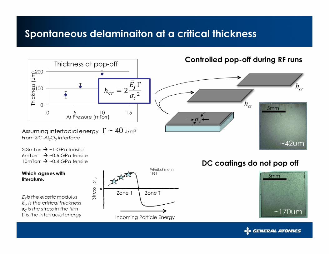
Thickness at pop-off
Spontaneous delaminaiton at a critical thickness
Incoming Particle Energy
Stre
ss σ
c
Zone 1 Zone T
Windischmann, 1991
DC coatings do not pop off
Controlled pop-off during RF runs
~170um
~42um
hcr
hcr
5mm
5mm
σc
Greg Randall [email protected]
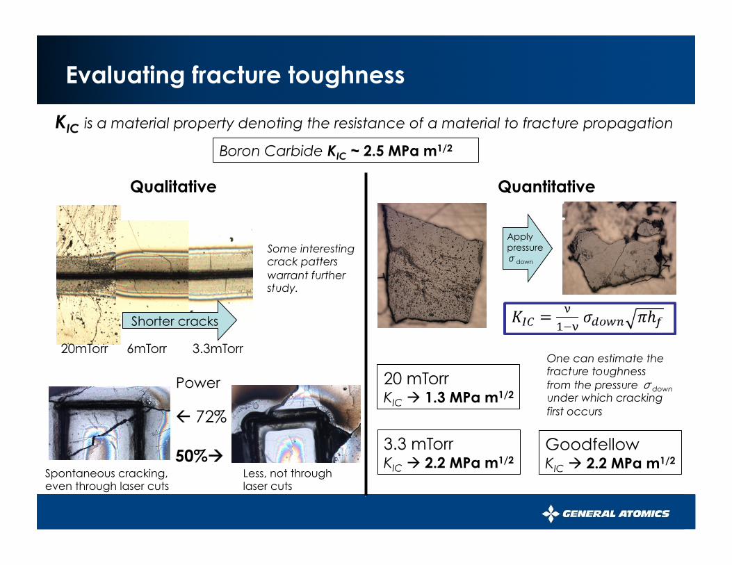
20 mTorr KIC 1.3 MPa m1/2
3.3 mTorr KIC 2.2 MPa m1/2
Goodfellow KIC 2.2 MPa m1/2
One can estimate the fracture toughness from the pressure σdown under which cracking first occurs 72%
50% Spontaneous cracking, even through laser cuts
Less, not through laser cuts
Power
20mTorr 6mTorr 3.3mTorr
Evaluating fracture toughness
KIC is a material property denoting the resistance of a material to fracture propagation
Boron Carbide KIC ~ 2.5 MPa m1/2
Qualitative Quantitative
Some interesting crack patters warrant further study.
Apply pressure σdown
Shorter cracks

Greg Randall [email protected]
Conclusions from my work this summer
• Achieved more control over the sputtering process – Controllable pop-offs and coatings that remain on
Al2O3 substrates – Predictable trend found in coating stress
• Obtained coatings with better properties – Approaching Zone T microstructure – Near-theoretical fracture toughness – Consistent density

Greg Randall [email protected]
Recommendations for future work on the subject
• Plasma-enhanced sputtering • Determining interfacial energy involved • More precise strength and toughness testing
– Microhardness on the way
• Auger standard for more reliable B/C ratio • XRD testing on DC runs to check for
crystallinity • Stress calculations from laser cutting • Polishing studies • Coating on curved surfaces

Greg Randall [email protected]
Acknowledgements
• Greg Randall
• Hongwei Xu
• Jack Knipping • Don Wall • Chris Hill