characterization and evaluation of la0.8 sr0.2co0.8 ni0.2o3-δ prepared by a polymer-assisted...
TRANSCRIPT

i n t e r n a t i o n a l j o u r n a l o f h y d r o g e n e n e r g y 3 4 ( 2 0 0 9 ) 6 8 4 5 – 6 8 5 1
Avai lab le a t www.sc iencedi rec t .com
j ourna l homepage : www.e lsev ier . com/ loca te /he
Characterization and evaluation of La0.8 Sr0.2Co0.8
Ni0.2O3-d prepared by a polymer-assisted combustionsynthesis as a cathode material for intermediatetemperature solid oxide fuel cells
Jing Chena, Fengli Lianga, Lina Liua, San Ping Jiangb,*, Li Jiana,**aSchool of Materials Science and Engineering, State Key Laboratory of Material Processing and Die & Mould Technology,
Huazhong University of Science and Technology, Wuhan, Hubei 430074, PR ChinabSchool of Mechanical and Aerospace Engineering, Nanyang Technological University, Singapore 639798
a r t i c l e i n f o
Article history:
Received 6 January 2009
Received in revised form
18 March 2009
Accepted 29 May 2009
Available online 24 June 2009
Keywords:
La0.8Sr0.2Co0.8Ni0.2O3-d
LSCN
Polymer-assisted combustion
synthesis
Nano-structured
Cathode
SOFC
* Corresponding author.** Corresponding author. Tel.: þ86 027 875578
E-mail addresses: [email protected] (0360-3199/$ – see front matter ª 2009 Interndoi:10.1016/j.ijhydene.2009.05.124
a b s t r a c t
A modified polymer-assisted combustion synthesis method is developed for preparation of
La0.8Sr0.2Co0.8Ni0.2O3-d (LSCN) nano-sized cathode particles by using organic additives
(glucose and acrylamide) and metal nitrates. The effect of the organic additives, pH value of
starting solution and calcination temperature on the formation of the LSCN perovskite
phase and microstructure of the powders is investigated. Chemical compatibility between
the LSCN and Y2O3 stabilized ZrO2 (YSZ) and Gd2O3 doped CeO2 (GDC) is evaluated and
electrochemical activity of LSCN cathode is evaluated. The prepared LSCN is chemically
compatible with the YSZ only at temperatures below 850 �C. The electrode area specific
resistance (ASR) is 0.30 and 0.10 U cm2 at 700 and 750 �C, respectively. These results suggest
that such prepared LSCN is a promising alternative cathode material for intermediate
temperature SOFCs.
ª 2009 International Association for Hydrogen Energy. Published by Elsevier Ltd. All rights
reserved.
1. Introduction reduced operating temperature are the increase in electrolyte
Solid oxide fuel cells (SOFCs) are considered as one of the most
promising energy conversion devices that exhibit advantages
of high efficiency, fuel flexibility and low environmental
pollution. Recently, significant progress has been achieved in
reducing the operation temperature of SOFCs from traditional
1000 �C to intermediate temperature range between 600 and
800 �C [1,2]. However, several major issues associated with the
49.S.P. Jiang), plumarrow@12ational Association for H
and electrode resistivities and the polarization losses of elec-
trode reactions, particularly the oxygen reduction reaction in
the cathode. In order to compensate for the ohmic losses at
lower temperatures, electrolytes with higher ionic conduc-
tivities and thin film electrolyte/electrode assemblies have
been developed [3,4]; and alternative cathode materials with
a high mixed ionic-electronic conductivity (MIEC) have been
employed. Compared to traditional La1�xSrxMnO3 (LSM)
6.com (L. Jian).ydrogen Energy. Published by Elsevier Ltd. All rights reserved.
i n t e r n a t i o n a l j o u r n a l o f h y d r o g e n e n e r g y 3 4 ( 2 0 0 9 ) 6 8 4 5 – 6 8 5 16846
perovskite cathode material, the MIECs can effectively
decrease the cathode polarization at reduced temperatures by
extending the reactive zones from the electrode–electrolyte
interface region to the whole body of the electrode [5,6].
Cathode material performance is very dependent on temper-
ature, grain size, microstructure and the formation or depo-
sition process [7], and the microstructure which is closely
related to the morphological characteristics of the starting
powder materials and the firing temperatures to fix the elec-
trode material on the electrolyte. The morphology of the
powder is affected by the synthesis techniques.
Perovskite cathode materials were prepared previously by
numerous methods, including EDTA-citric complex method
[8], sol–gel method [9], glycine–nitrate method [10,11], Pechini
method [12,13] and freeze–drying method [14]. In the present
study, a modified polymer-assisted combustion method is
introduced for the preparation of La0.8Sr0.2Co0.8Ni0.2O3-
d (LSCN). The thermal decomposition behavior of the gelled
precursor, the phase formation of the oxide and the
morphology of the powder were examined. The chemical
compatibility and electrocatalytic activity for the oxygen
reduction reaction were evaluated.
2. Experimental
2.1. Materials synthesis
The LSCN perovskite oxide powder was synthesized using
a modified polymer-assisted combustion synthesis method
with glucose and acrylamide as the fuel and dispersing
agent, respectively. In this method, stoichiometric amounts
of La(NO3)3$6H2O, Sr(NO3)2, Co(NO3)2$6H2O, Ni(NO3)2$6H2O,
C6H12O6$H2O and acrylamide (99.9%, Sinopharm Chemical
Reagent Co. Ltd) in 2:3 molar ratio were first dissolved in
distilled water under magnetic agitation. The water content in
the nitrates was confirmed by thermogravimetric analysis
(TG/DTA, PerkinElmer Instruments Co. Ltd.) at a heating rate
of 5 �C/min in flowing air. For most of the experiments (unless
otherwise stated), 5:1 molar ratio of the organic additives
(glucose and acrylamide) to the metal nitrates was used. In
order to study the effect of the organic additives on the phase
formationof the LSCN,themolar ratio wasvariedfrom2:1 to7:1.
Ammonia solution (25 wt%) was added into the solution drop-
wise under stirring. The pH value of the solution was controlled
withinthe range of 6 to10. Suchprepared solution was heatedto
180 �C in an oven for 10 h, forming a viscous gel and then
changing quickly to a porous and black-colored xerogel. Finally,
the xerogel was calcined at various temperatures between
450 �C and 800 �C for 2 h in air to form the oxide powders.
2.2. Materials characterization
The behavior of the xerogel during temperature increase was
analyzed by thermogravimetric analysis and differential
thermal analysis (TG/DTA, PerkinElmer Instruments Co. Ltd.).
The formed phase in calcined powders was identified by X-ray
diffraction (XRD) using a Phillips X’Pert Pro diffractometer
with Cu Ka radiation. The diffraction patterns were registered
over a 2q range between 20 and 80� and the lattice parameters
were calculated using the Jade-5 software (Material Data, Inc.).
The specific surface area of the powder calcined at 800 �C was
determined as 16.12 m2 g�1 by the BET method (Micromeritics
Instrument Co. Ltd.). The chemical compatibility between the
prepared LSCN powder and Y2O3 stabilized ZrO2 (TZ8Y, Tosoh,
Japan) and in-house Ce0.8Gd0.2O1.9 (GDC) electrolytes was
studied by firing LSCN/YSZ and LSCN/GDC mixed powders at
1:1 weight ratio at temperatures 800, 850, 900, 1000 and 1100 �C
in air for 10 h, followed by XRD phase analysis. A Sirion 200
scanning electron microscope (SEM) and a Tecnai G2 20
transmission electron microscopy (TEM) were employed to
examine the morphology of the LSCN powders.
Using a specimen sintered at 1450 �C for 2 h with a dimen-
sion of 5� 5� 20 mm, the coefficient of thermal expansion
(CTE) of the prepared LSCN was measured in air in the
temperature range of 30–1000 �C by a DIL402C thermal
mechanical analyzer (NETZSCH Ltd.); and the electrical
conductivity of the prepared LSCN was measured by a DC
four-point method at temperatures ranging from 50 �C to
1000 �C in flowing air.
2.3. Electrocatalytic activity evaluation
Electrolyte substrates were prepared by die pressing 8% mol
Y2O3–ZrO2 powder (YSZ, Tosoh, Japan), followed by sintering
at 1500 �C for 4hrs in air. The substrate disks were 21 mm in
diameter and 1.2 mm in thickness. For preparing LSCN elec-
trodes onto YSZ electrolyte disks with a thin GDC buffer layer
of approximately 8 mm in between, the GDC buffer layer was
firstly applied to the YSZ electrolyte disk by paste screen
printing, followed by sintering at 1250 �C for 2 h in air. The
LSCN paste was then screen printed on the buffer layer and
sintered at 1000 �C for 2 h in air to form the cathode with
a thickness of 8 to 10 mm and an active area of 0.5 cm2. 5 wt%
cellulose binder was used for preparing the pastes. For elec-
trochemical impedance measurement of the cathode, Pt paste
was painted on top of the cathode and was fired at 850 �C for
2 h as the current collector and on the opposite side of the
electrolyte disk as the counter and reference electrodes. The
counter electrode was positioned symmetrically opposite to
the working electrode and the reference electrode was a ring
at the edge of the electrolyte substrate. Electrochemical
impedance spectra of the above prepared cells were obtained
in a frequency range of 0.1 Hz to 100 kHz with signal ampli-
tude of 10 mV at temperatures between 600 and 750 �C using
an impedance/gain phase analyzer (Solartron 1260) and an
electrochemical interface analyzer (Solartron 1287) at open
circuit. The electrode interface (polarization) resistance (RE)
was derived from the difference between the low- and high-
frequency intercepts at the real impedance axis. The cross-
sectioned morphology of the specimen assembly was
observed by the SEM mentioned above.
3. Results and discussion
3.1. Thermal analysis of precursor powders
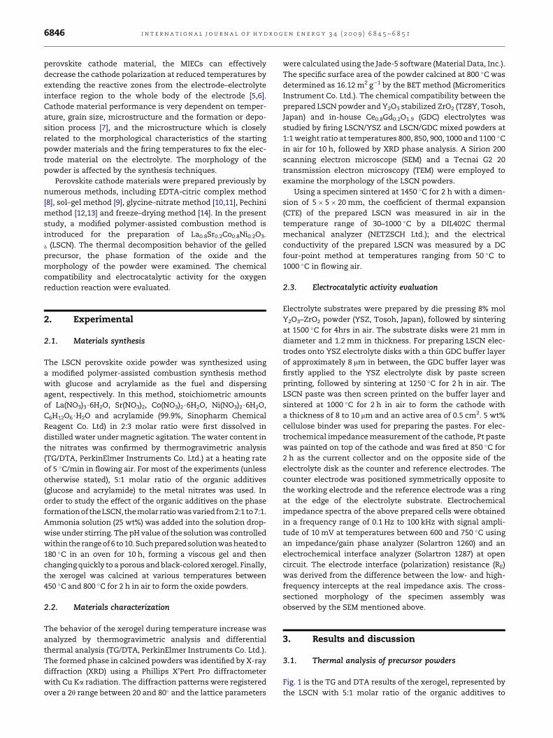
Fig. 1 is the TG and DTA results of the xerogel, represented by
the LSCN with 5:1 molar ratio of the organic additives to

Fig. 1 – TG-DTA curves of LSCN xerogel after the heat
treatment at 180 8C. Fig. 3 – SEM micrographs of LSCN powder sintered at 800 8C
for 2hrs.
i n t e r n a t i o n a l j o u r n a l o f h y d r o g e n e n e r g y 3 4 ( 2 0 0 9 ) 6 8 4 5 – 6 8 5 1 6847
nitrates. With temperature increase, the weight of the xerogel
sample decreases as expected. Three weight loss steps are
observed in the TG curve between 30–224, 224–396, and 396–
424 �C, corresponding the exothermic peaks at around 311 �C
and near 414 �C in the DTA curve. They are caused by residual
water removal, decomposition and oxidation of organic
additives [9,15] and burning out of nitrate radicals, respec-
tively. With temperature increase above 424 �C, the weight
loss is not significant, and formation of the LSCN perovskite
phase is initialized.
3.2. Phase identification and morphological examination
Fig. 2 shows the XRD patterns of the LSCN xerogels calcined at
various temperatures above 450 �C in air for 2 h. The rudiment
of perovskite phase starts to appear at 500 �C with poor crys-
tallinity indicated by the tiny peaks. Diffraction peaks of the
Fig. 2 – XRD patterns of LSCN powders calcined at different
temperatures for 2hrs in air.
calcined xerogel become noticeable when the calcination
temperature was increased to 600 �C; a well-crystallized LSCN
with a rhombohedral perovskite structure is presented. The
diffraction peaks turn out to be sharper with further
increasing the calcination temperature and the corresponding
grain size is increased in the range between 20 to 30 nm esti-
mated by the Scherrer equation incorporated in the Jade-5. For
all solution formulas, single-phased LSCN were synthesized
by the modified combustion method at calcination tempera-
ture as low as 600 �C. Fig. 3 is the morphology of the LSCN
powder. The particles exhibit a narrow size distribution in the
range of 20–50 nm with slight agglomeration. The morphology
of the LSCN powders is similar to that of La0.6Sr0.4CoO3-x,
La0.6Sr0.4Fe0.8Co0.2O3-x and LSCN powders synthesized by the
glycine–nitrate process [16,17] and the Pechini method [12].
Shown in Fig. 4 is the XRD patterns of the LSCN powders
prepared with different pH values and calcined at 800 �C for
Fig. 4 – The XRD patterns of the LSCN powders prepared
with different pH values and calcined at 800 8C for 2 h in
air.

Fig. 5 – TEM micrographs of LSCN powders synthesized with various pH values starting solutions: (a) pH [ 6; (b) pH [ 8; (c)
pH [ 10. The powders were calcined at 800 8C for 2hrs in air.
i n t e r n a t i o n a l j o u r n a l o f h y d r o g e n e n e r g y 3 4 ( 2 0 0 9 ) 6 8 4 5 – 6 8 5 16848
2 h in air. All the samples display identical diffraction
patterns, indicating the formation of a rhombohedral perov-
skite phase and the same crystalline size of w30 nm according
to the Scherrer formula. Therefore, it can be concluded that
variation of pH value between 6 and 10 has no effect on LSCN
phase formation and particle size of the powders, even though
the viscosity of the prepared solution was changed. Fig. 5
shows the TEM micrographs of LSCN powders calcined at
800 �C for 2 h in air with various solution pH values. The small
particles are agglomerated, and the average particle size is in
the neighborhood of 30 nm.
3.3. Effect of the ratio of organic additive to metal nitrate
Another important parameter affecting LSCN phase forma-
tion is the molar ratio of the organic additives to the metal
nitrates. Fig. 6 shows the XRD patterns of the LSCN powders
synthesized with variation of the ratio. It is noticed no
impurity phase was formed with the 5:1 molar ratio; and in all
other cases, an impurity phase La4Ni3O10 was appeared. The
Fig. 6 – XRD patterns of LSCN powders synthesized with
various molar ratios of the organic additives to the metal
nitrates. The powders were calcined at 800 8C for 2 h in air.
diffraction peaks from the impurity phase near 25� are turned
out to be more obvious at the lower ratios owing to the lack of
blocking effect of organic additives on suppressing impurity
formation [18]; however, excessive content of the organic
additives is also prone to the formation of the impurity
possibly due to excess of fuel and the high combustion
temperature [19,20]. Fig. 7 shows the TEM micrograph of the
LSCN powders prepared at 2:1 ratio for comparison with that
shown in Fig. 5c, the particle size of the LSCN with 2:1 ratio is
significantly larger than that with 5:1 ratio. The organic
additives of glucose and acrylamide act not only as the fuel,
but also as the chelate agent. Glucose may degrade in alkaline
solution at about 150 �C into lactic acid, formate, glycolic acid,
and acetate [21], forming complexes with metal cations. On
the other hand, acrylamide itself is an effective complex
Fig. 7 – TEM micrograph of LSCN powders synthesized with
2:1 molar ratio of the organic additives to the metal nitrates
and a pH of 10. The powders were calcined at 800 8C for
2hrs in air.

Fig. 9 – SEM micrographs of fractured cross-section of LSCN
electrode.
i n t e r n a t i o n a l j o u r n a l o f h y d r o g e n e n e r g y 3 4 ( 2 0 0 9 ) 6 8 4 5 – 6 8 5 1 6849
forming agent with metal cations due to the amine group [20].
A proper ratio of the organic additives to nitrates is beneficial
for the metal ions to be completely engaged into the
complexes, leading to simultaneous complete combustion
and phase formation. Less than that, metallic cations cannot
be fully complexed, resulting in incomplete combustion and
phase separation. The ratio of 5:1 seems to be in the vicinity of
the critical value.
3.4. Chemical and thermal compatibility
The chemical compatibility of the LSCN with the YSZ and GDC
electrolyte was investigated by firing the mixed powders at
800, 850, 900, 1000, 1100 �C for 10 h. Fig. 8 shows the XRD
patterns of the sintered LSCN/YSZ and LSCN/GDC mixture.
The results show that the LSCN reacts readily with the YSZ to
form La2Zr2O7 and SrZrO3 phases at temperatures above
800 �C; however, the GDC is chemically inert to the LSCN at all
sintering temperatures up to 1100 �C. Thus, in order to use the
LSCN cathode with the YSZ electrolyte, a GDC interlayer is
conventionally required to prevent the formation of resistive
La2Zr2O7 and SrZrO3 phases during cell preparation.
Fig. 8 – XRD patterns of (a) LSCN/YSZ and (b) LSCN/GDC
mixtures sintered at 800, 850, 900, 1000, 1100 8C in air for
10 h.
The CTE of the prepared LSCN is 16.67� 10�6 K�1 and quite
comparable to those reported in references [12] (16.5� 10�6 K�1)
and [14] (15.6� 10�6 K�1). For the most commonly used YSZ
electrolyte, its CTE is in the range of 10.3–10.5� 10�6 K�1 in the
temperature range from 50 to 1000 �C in air atmosphere; and for
the GDC electrolyte, its CTE is between 11.8� 10�6 K�1 and
13.4� 10�6 K�1 depending on the content of doping [21,22].
Therefore, the LSCN is more thermally compatible with the
GDC electrolyte than the YSZ.
3.5. Electrical conductivity and electrocatalytic activity
The total electrical conductivity of the prepared LSCN
measured by the DC four-point method is 1243 S cm�1 at
800 �C and 2379 S cm�1 at room temperature, which is close to
the values reported in reference [11] and exhibits the charac-
teristic of temperature dependence of metallic materials. This
total electrical conductivity includes the electronic and ionic
contribution; however, the ionic contribution is almost
negligible compared to the electronic contribution as the
difference between them is several orders of magnitude. Such
a high electrical conductivity can meet the requirement of
a SOFC cathode.
Fig. 9 is the SEM micrograph of the cross-sectioned spec-
imen assembly for electrochemical impedance measurement,
showing a layered structure of Pt current collector, cathode,
the GDC buffer and the YSZ electrolyte substrate and
adequate adherence between them. With this half cell, elec-
trochemical impedance spectra of the LSCN electrode at
temperatures between 600 and 750 �C in air were obtained, as
shown in Fig. 10. The O2 reduction reaction on the LSCN
electrode is characterized by a depressed impedance arc over
the temperature range studied and there was no clear sepa-
ration between low- and high- frequency arcs. The cathode
polarization resistance (RE) at open circuit condition for the O2
reduction reaction in air, obtained from the distance between
the high- and low-frequency intercepts of the arc on the real
axis, is 2.69, 0.65, 0.30, and 0.10 U cm2 at 600, 650, 700, and
750 �C, respectively. The corresponding activation energy is

Fig. 10 – Impedance spectra of LSCN electrode measured at
different temperatures in air.
i n t e r n a t i o n a l j o u r n a l o f h y d r o g e n e n e r g y 3 4 ( 2 0 0 9 ) 6 8 4 5 – 6 8 5 16850
1.64� 0.03 eV. These results are in the vicinity of that reported
with La0.8Sr0.2Co0.98Ni0.02O3-d [10], (La0.8Sr0.2)0.99Co0.8Ni0.2O3-
d [11] and LSCF [22,23] cathodes, which suggests that such
prepared LSCN with high electrocatalytic activity and sub-
micron sized microstructure be a promising alternative
cathode material for intermediate temperature SOFCs.
4. Conclusions
Based on the present study, the following conclusions can be
made:
1) The modified polymer-assisted combustion process is
suitable for the synthesis of the LSCN nano-sized powders.
The rhombohedral LSCN perovskite structure forms at
calcination temperature above 600 �C.
2) The pH value of the starting solution between 6 and 10 has
no significant effect on the formation and morphology of
LSCN phase; however, the ratio of the organic additives
(glucose and acrylamide) to the metal nitrates affects the
formation of pure LSCN phase. 5:1 ratio seems to be an
appropriate choice for forming single LSCN phase without
impurity of La4Ni3O10.
3) The prepared LSCN is chemically compatible with the GDC
and YSZ electrolytes at temperatures below 1100 �C and
850 �C, respectively, and thermally matched to the GDC
better than the YSZ.
4) Such prepared LSCN with polarization resistances of 0.30
and 0.10 U cm2 at 700 and 750 �C, respectively, demon-
strates a comparable polarization resistance to the state of
the art cathode LSCF, suggesting the potential of being
a promising alternate cathode material for intermediate
temperature SOFCs.
Acknowledgements
This research was financially supported by the NSFC project
50571038 and the national ‘‘863’’ project 2006AA05Z148. SEM
and XRD characterizations were assisted by the Analytical and
Testing Center of Huazhong University of Science and
Technology.
r e f e r e n c e s
[1] Fergus JW. Sealants for solid oxide fuel cells. Journal of PowerSources 2005;147:46–57.
[2] Dusastre V, Kilner JA. Optimisation of composite cathodesfor intermediate temperature SOFC applications. Solid StateIonics 1999;126:163–74.
[3] Mai A, Haanappel VAC, Tietz F, Stover D. Ferrite-basedperovskites as cathode materials for anode-supported solidoxide fuel cells. Part II. Influence of the CGO interlayer. SolidState Ionics 2006;177:2103–7.
[4] Mai A, Haanappel VAC, Uhlenbruck S, Tietz F, Stover D.Ferrite-based perovskites as cathode materials for anode-supported solid oxide fuel cells: Part I. Variation ofcomposition. Solid State Ionics 2005;176:1341–50.
[5] Perry Murray E, Sever MJ, Barnett SA. Electrochemicalperformance of (La, Sr) (Co, Fe)O3-(Ce, Gd)O3 compositecathodes. Solid State Ionics 2002;148:27–34.
[6] Adler SB. Factors governing oxygen reduction in solid oxidefuel cell cathodes. Chemical Reviews 2004;104:4791–843.
[7] Wincewicz KC, Cooper JS. Taxonomies of SOFC material andmanufacturing alternatives. Journal of Power Sources 2005;140:280–96.
[8] Zhou W, Ran R, Shao ZP, Gu HX, Jin WQ, Xu NP. Significantimpact of nitric acid treatment on the cathode performanceof Ba0.5Sr0.5Co0.8Fe0.2O3-[delta] perovskite oxide viacombined EDTA-citric complexing process. Journal of PowerSources 2007;174:237–45.
[9] Bilger S, Syskakis E, Naoumidis A, Nickel H. Sol–gel synthesisof strontium-doped lanthanum manganite. Journal ofAmerican Ceramic Society 1992;75:964–70.
[10] Shaw CKM, Kilner JA, Skinner SJ. Mixed cobalt and nickelcontaining perovskite oxide for intermediate temperatureelectrochemicalapplications.SolidState Ionics 2000;135:765–9.
[11] Hjalmarsson P, Søgaard M, Hagen A, Mogensen M. Structuralproperties and electrochemical performance of strontium-and nickel-substituted lanthanum cobaltite. Solid StateIonics 2008;179:636–46.
[12] Chai YL, Ray DT, Chen GJ, Chang YH. Synthesis of La0.8Sr0.
2Co0.5Ni0.5O3-[delta] thin films for high sensitivity CO sensingmaterial using the Pechini process. Journal of Alloys andCompounds 2002;333:147–53.
[13] Huang K, Lee HY, Goodenough JB. Sr- and Ni-doped LaCoO3
and LaFeO3 perovskites. New cathode materials for solid-oxide fuel cells. Journal of the Electrochemical Society 1998;145:3220–7.
[14] Kirchnerova J, Klvana D, Vaillancourt J, Chaouki J. Evaluationof some cobalt and nickel based perovskites prepared byfreeze–drying as combustion catalysts. Catalysis Letters1993;21:77–87.
[15] Tang ZL, Xie YS, Hawthorne H, Ghosh D. Sol–gel processingof Sr0.5Sm0.5CoO3 film. Journal of Power Sources 2006;157:385–8.
[16] Ji Y, Liu J, He TM, Cong LG, Wang JX, Su WH. Singleintermedium-temperature SOFC prepared by glycine–nitrate process. Journal of Alloys and Compounds 2003;353:257–62.
[17] Murata K, Fukui T, Abe H, Naito M, Nogi K. Morphologycontrol of La(Sr)Fe(Co)O3-a cathodes for IT-SOFCs. Journal ofPower Sources 2005;145:257–61.
[18] Lenormand P, Castillo S, Gonzalez JR, Laberty-Robert C,Ansart F. Lanthanum ferromanganites thin films by sol–gelprocess. Influence of the organic/inorganic R ratio on themicrostructural properties. Solid State Sciences 2005;7:159–63.
[19] Guo RS, Wei QT, Li HL, Wang FH. Synthesis and properties ofLa0.7Sr0.3MnO3 cathode by gel combustion. Materials Letters2006;60:261–5.

i n t e r n a t i o n a l j o u r n a l o f h y d r o g e n e n e r g y 3 4 ( 2 0 0 9 ) 6 8 4 5 – 6 8 5 1 6851
[20] Chick LA, Pederson LR, Maupin GD, Bates JL,Thomas LE, Exarhos GJ. Glycine–nitrate combustionsynthesis of oxide ceramic powders. Materials Letters1990;10:6–12.
[21] Ellis AV, Wilson MA. Carbon exchange in hot alkalinedegradation of glucose. Journal of Organic Chemistry 2002;67:8469–74.
[22] Esquirol A, Kilner J, Brandon N. Oxygen transport in La0.6Sr0.
4Co0.2Fe0.8O3-[delta]/Ce0.8Ge0.2O2-x composite cathode for IT-SOFCs. Solid State Ionics 2004;175:63–7.
[23] Fu C, Sun K, Zhang N, Chen X, Zhou D. Electrochemicalcharacteristics of LSCF-SDC composite cathode forintermediate temperature SOFC. Electrochimca Acta 2007;52:4589–94.