characteristics of terrestrial imt-advanced systems for ... · rep. itu-r m.2292-0 1 report itu-r...
TRANSCRIPT
Report ITU-R M.2292-0(12/2013)
Characteristics of terrestrial IMT-Advanced systems for frequency sharing/
interference analyses
M Series
Mobile, radiodetermination, amateurand related satellite services
ii Rep. ITU-R M.2292-0
Foreword
The role of the Radiocommunication Sector is to ensure the rational, equitable, efficient and economical use of the radio-frequency spectrum by all radiocommunication services, including satellite services, and carry out studies without limit of frequency range on the basis of which Recommendations are adopted.
The regulatory and policy functions of the Radiocommunication Sector are performed by World and Regional Radiocommunication Conferences and Radiocommunication Assemblies supported by Study Groups.
Policy on Intellectual Property Right (IPR)
ITU-R policy on IPR is described in the Common Patent Policy for ITU-T/ITU-R/ISO/IEC referenced in Annex 1 of Resolution ITU-R 1. Forms to be used for the submission of patent statements and licensing declarations by patent holders are available from http://www.itu.int/ITU-R/go/patents/en where the Guidelines for Implementation of the Common Patent Policy for ITU-T/ITU-R/ISO/IEC and the ITU-R patent information database can also be found.
Series of ITU-R Reports
(Also available online at http://www.itu.int/publ/R-REP/en)
Series Title
BO Satellite delivery
BR Recording for production, archival and play-out; film for television
BS Broadcasting service (sound)
BT Broadcasting service (television)
F Fixed service
M Mobile, radiodetermination, amateur and related satellite services
P Radiowave propagation
RA Radio astronomy
RS Remote sensing systems
S Fixed-satellite service
SA Space applications and meteorology
SF Frequency sharing and coordination between fixed-satellite and fixed service systems
SM Spectrum management
Note: This ITU-R Report was approved in English by the Study Group under the procedure detailed in Resolution ITU-R 1.
Electronic Publication Geneva, 2014
ITU 2014
All rights reserved. No part of this publication may be reproduced, by any means whatsoever, without written permission of ITU.
Rep. ITU-R M.2292-0 1
REPORT ITU-R M.2292-0
Characteristics of terrestrial IMT-Advanced systems for frequency sharing/interference analyses
(2013)
1 Introduction
IMT systems have been the main method of delivering wide area mobile broadband applications. In order to accommodate increasing amount of mobile traffic and user demand for higher data rates, IMT-Advanced which is evolution of IMT-2000, is planned to be deployed in the world.
Frequency sharing studies and interference analyses involving IMT systems and other systems and services operating in the same or the adjacent bands may need to be undertaken within ITU-R. To perform the necessary sharing studies between IMT systems and systems in other services, characteristics of the terrestrial component of IMT-Advanced systems are needed.
This Report provides the baseline characteristics of terrestrial IMT-Advanced systems for use of sharing and compatibility studies between IMT-Advanced systems and other systems and services.
It should be noted that in case of parameters having a range of values, “typical” values should be used in sharing studies, where applicable.
2 Acronyms
ACLR Adjacent channel leakage power ratio
ACS Adjacent channel selectivity
EIRP Equivalent isotropically radiated power
FDD Frequency division duplex
FFR Fractional frequency reuse
IMT International Mobile Telecommunications
LTE Long-term evolution
OOBE Out-of-band emission
TDD Time division duplex
OFDM Orthogonal frequency division multiplexing
SC-FDMA Single carrier frequency division multiple access
3 Related Recommendations and Reports
Recommendation ITU-R F.1336: Reference radiation patterns of omnidirectional, sectoral and other antennas in point-to-multipoint systems for use in sharing studies in the frequency range from 1 GHz to about 70 GHz
Recommendation ITU-R P.1238: Propagation data and prediction methods for the planning of indoor radiocommunication systems and radio local area networks in the frequency range 900 MHz to 100 GHz
2 Rep. ITU-R M.2292-0
Report ITU-R M.2039: Characteristics of terrestrial IMT-2000 systems for frequency sharing/interference analyses
Report ITU-R M.2241: Compatibility studies in relation to Resolution 224 in the bands 698-806 MHz and 790-862 MHz.
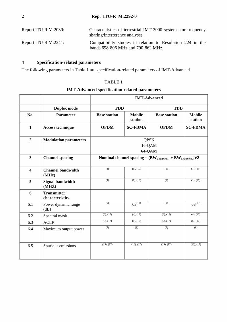
4 Specification-related parameters
The following parameters in Table 1 are specification-related parameters of IMT-Advanced.
TABLE 1
IMT-Advanced specification related parameters
IMT-Advanced
Duplex mode FDD TDD
No. Parameter Base station Mobile station
Base station Mobile station
1 Access technique OFDM SC-FDMA OFDM SC-FDMA
2 Modulation parameters QPSK 16-QAM 64-QAM
3 Channel spacing Nominal channel spacing = (BWChannel(1) + BWChannel((2))/2
4 Channel bandwidth (MHz)
(1) (1), (19) (1) (1), (19)
5 Signal bandwidth (MHZ)
(1) (1), (19) (1) (1), (19)
6 Transmitter characteristics
6.1 Power dynamic range (dB)
(2) 63(18) (2) 63(18)
6.2 Spectral mask (3), (17) (4), (17) (3), (17) (4), (17)
6.3 ACLR (5), (17) (6), (17) (5), (17) (6), (17)
6.4 Maximum output power (7) (8) (7) (8)
6.5 Spurious emissions (15), (17) (16), (17) (15), (17) (16), (17)
Rep. ITU-R M.2292-0 3
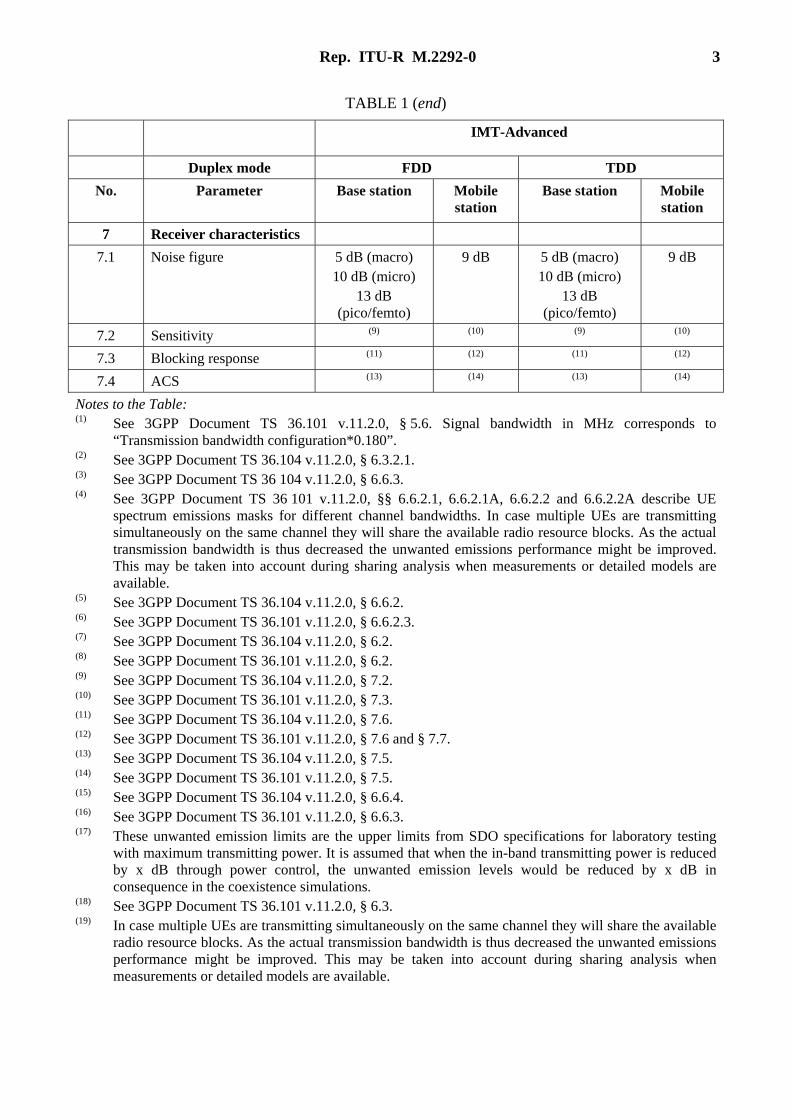
TABLE 1 (end)
IMT-Advanced
Duplex mode FDD TDD
No. Parameter Base station Mobile station
Base station Mobile station
7 Receiver characteristics
7.1 Noise figure 5 dB (macro) 10 dB (micro)
13 dB (pico/femto)
9 dB 5 dB (macro) 10 dB (micro)
13 dB (pico/femto)
9 dB
7.2 Sensitivity (9) (10) (9) (10)
7.3 Blocking response (11) (12) (11) (12)
7.4 ACS (13) (14) (13) (14)
Notes to the Table: (1) See 3GPP Document TS 36.101 v.11.2.0, § 5.6. Signal bandwidth in MHz corresponds to
“Transmission bandwidth configuration*0.180”. (2) See 3GPP Document TS 36.104 v.11.2.0, § 6.3.2.1. (3) See 3GPP Document TS 36 104 v.11.2.0, § 6.6.3. (4) See 3GPP Document TS 36 101 v.11.2.0, §§ 6.6.2.1, 6.6.2.1A, 6.6.2.2 and 6.6.2.2A describe UE
spectrum emissions masks for different channel bandwidths. In case multiple UEs are transmitting simultaneously on the same channel they will share the available radio resource blocks. As the actual transmission bandwidth is thus decreased the unwanted emissions performance might be improved. This may be taken into account during sharing analysis when measurements or detailed models are available.
(5) See 3GPP Document TS 36.104 v.11.2.0, § 6.6.2. (6) See 3GPP Document TS 36.101 v.11.2.0, § 6.6.2.3. (7) See 3GPP Document TS 36.104 v.11.2.0, § 6.2. (8) See 3GPP Document TS 36.101 v.11.2.0, § 6.2. (9) See 3GPP Document TS 36.104 v.11.2.0, § 7.2. (10) See 3GPP Document TS 36.101 v.11.2.0, § 7.3. (11) See 3GPP Document TS 36.104 v.11.2.0, § 7.6. (12) See 3GPP Document TS 36.101 v.11.2.0, § 7.6 and § 7.7. (13) See 3GPP Document TS 36.104 v.11.2.0, § 7.5. (14) See 3GPP Document TS 36.101 v.11.2.0, § 7.5. (15) See 3GPP Document TS 36.104 v.11.2.0, § 6.6.4. (16) See 3GPP Document TS 36.101 v.11.2.0, § 6.6.3. (17) These unwanted emission limits are the upper limits from SDO specifications for laboratory testing
with maximum transmitting power. It is assumed that when the in-band transmitting power is reduced by x dB through power control, the unwanted emission levels would be reduced by x dB in consequence in the coexistence simulations.
(18) See 3GPP Document TS 36.101 v.11.2.0, § 6.3. (19) In case multiple UEs are transmitting simultaneously on the same channel they will share the available
radio resource blocks. As the actual transmission bandwidth is thus decreased the unwanted emissions performance might be improved. This may be taken into account during sharing analysis when measurements or detailed models are available.
4 Rep. ITU-R M.2292-0
References
(Documents publically available at http://www.3gpp.org/specification-numbering)
[1] TR 25.942 v.11.0.0 3rd Generation Partnership Project; Technical Specification Group Radio Access Networks; RF System Scenarios (Release 11).
[2] TS 36.101 v.11.2.0, 3rd Generation Partnership Project; Technical Specification Group Radio Access Networks; Evolved Universal Terrestrial Radio Access (E-UTRA); User Equipment (UE) radio transmission and reception (Release 11).
[3] TS 36.104 v.11.2.0, 3rd Generation Partnership Project; Technical Specification Group Radio Access Networks; Evolved Universal Terrestrial Radio Access (E-UTRA); Base Station (BS) radio transmission and reception (Release 11).
[4] TR 36.942 v.11.0.0 3rd Generation Partnership Project; Technical Specification Group Radio Access Network; Evolved Universal Terrestrial Radio Access (E-UTRA); Radio Frequency (RF) system scenarios (Release 11) – Note this is a working document.
[5] 3GPP TR 36.912 v.11.0.0 3rd Generation Partnership Project; Technical Specification Group Radio Access Network; Feasibility study for Further Advancements for E-UTRA (LTE-Advanced) (Release 11) – Section 16.
5 Deployment-related parameters
This section describes and proposes values for typical deployment parameters for different deployment scenarios and in different frequency bands. In many cases, the values of these parameters vary within a range, but to facilitate sharing studies wherever possible a single value has been chosen that is representative for use in sharing studies.
These parameter values are appropriate for studies concerning the impact of a single IMT cell operating in the presence of another system/service. For some parameters such as transmitted power levels, however, studies to assess the impact of an entire IMT network will in some cases need to take account of the varying nature of an IMT network, in particular power control. Inter-cell interference must be minimized and parameters such as power levels adjusted in order to optimize the operational performance and capacity of the network.
5.1 Base station characteristics and cell structure
Deployment-dependent parameters describing the cell structure and other base station related parameters needed to conduct sharing studies are summarized below. In addition, it should be stressed that in the sharing studies it is necessary to select the appropriate deployment type (macro rural/suburban/urban, small cell outdoor/indoor), that corresponds to expected usage of a certain frequency band, as indicated in the parameter tables. For nationwide studies a combination of deployment types could be considered.
Rep. ITU-R M.2292-0 5
5.1.1 Cell size and base station density
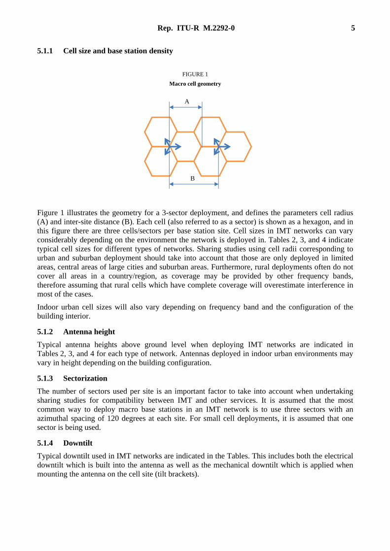
FIGURE 1
Macro cell geometry
Figure 1 illustrates the geometry for a 3-sector deployment, and defines the parameters cell radius (A) and inter-site distance (B). Each cell (also referred to as a sector) is shown as a hexagon, and in this figure there are three cells/sectors per base station site. Cell sizes in IMT networks can vary considerably depending on the environment the network is deployed in. Tables 2, 3, and 4 indicate typical cell sizes for different types of networks. Sharing studies using cell radii corresponding to urban and suburban deployment should take into account that those are only deployed in limited areas, central areas of large cities and suburban areas. Furthermore, rural deployments often do not cover all areas in a country/region, as coverage may be provided by other frequency bands, therefore assuming that rural cells which have complete coverage will overestimate interference in most of the cases.
Indoor urban cell sizes will also vary depending on frequency band and the configuration of the building interior.
5.1.2 Antenna height
Typical antenna heights above ground level when deploying IMT networks are indicated in Tables 2, 3, and 4 for each type of network. Antennas deployed in indoor urban environments may vary in height depending on the building configuration.
5.1.3 Sectorization
The number of sectors used per site is an important factor to take into account when undertaking sharing studies for compatibility between IMT and other services. It is assumed that the most common way to deploy macro base stations in an IMT network is to use three sectors with an azimuthal spacing of 120 degrees at each site. For small cell deployments, it is assumed that one sector is being used.
5.1.4 Downtilt
Typical downtilt used in IMT networks are indicated in the Tables. This includes both the electrical downtilt which is built into the antenna as well as the mechanical downtilt which is applied when mounting the antenna on the cell site (tilt brackets).
B
A
6 Rep. ITU-R M.2292-0
5.1.5 Frequency reuse
Typical frequency reuse figures used for IMT networks are 1 or 3 but a frequency reuse of 1 is the most common one and it is proposed to be used for all scenarios. Fractional frequency reuse (FFR) may also be used in some IMT network deployments but this option is not included in the Tables.
5.1.6 Antenna pattern
Recommendation ITU-R F.1336 has been used in the past when conducting sharing studies. It should be noted that the Recommendation states that “it is essential that every effort be made to utilize the actual antenna pattern in coordination studies and interference assessment” (Note 1 to recommends 1). In the Tables below, parameters to be used with Recommendation ITU-R F.1336 are proposed. These parameters apply to recommends 3.1 of Recommendation ITU-R F.1336. The parameters are intended for use in sharing studies. The parameter values are applicable for both average and peak side lobes, noting that the equations for average and peak side lobes are not identical, and are valid in the frequency range 400-6 000 MHz. To implement a tilt it is only necessary to apply a tilt angle value in the equations for the vertical patterns in recommends 3.1 to obtain the corresponding tilted antenna pattern.
5.1.7 Indoor base station deployment
Base stations are often installed indoors especially in urban areas. Typical percentages of base stations deployed indoors for the different deployment scenarios are indicated in Tables 3 and 4. Values for indoor penetration loss reflect values used for network planning based on practical experience. It is proposed that the floor loss model of Recommendation ITU-R P.1238 be used to determine building penetration loss in the vertical direction (§ 3.1, Table 3). Building entry loss values in horizontal direction for certain frequency ranges could be found in Recommendation ITU-R P.1812 (Table 6).
5.1.8 Below rooftop base station antenna deployment
When conducting sharing studies it is also important to account for how the antennas are deployed in relation to the surrounding environment, including the clutter. If the antennas are deployed below the rooftop level it might be necessary to use a different propagation model compared to the scenario when the antennas are installed above the roof top level. Tables 2, 3, and 4 indicate the typical percentage of base station antennas installed below the rooftop level. An alternative approach could be to add clutter loss to propagation loss calculations.
5.1.9 Maximum and average base station output power
Maximum output powers from base stations are indicated in Tables 2, 3, and 4 for each environment. Additionally, typical average activity of a base station and corresponding average output powers during busy hour are indicated in the Tables. For further details, see Report ITU-R M.2241, § 2.2.3.2. The choice between maximum or average output power depends on the type of study.
In case TDD is used, base station downlink transmission occurs only part of the time, which will further reduce average base station power.
Rep. ITU-R M.2292-0 7
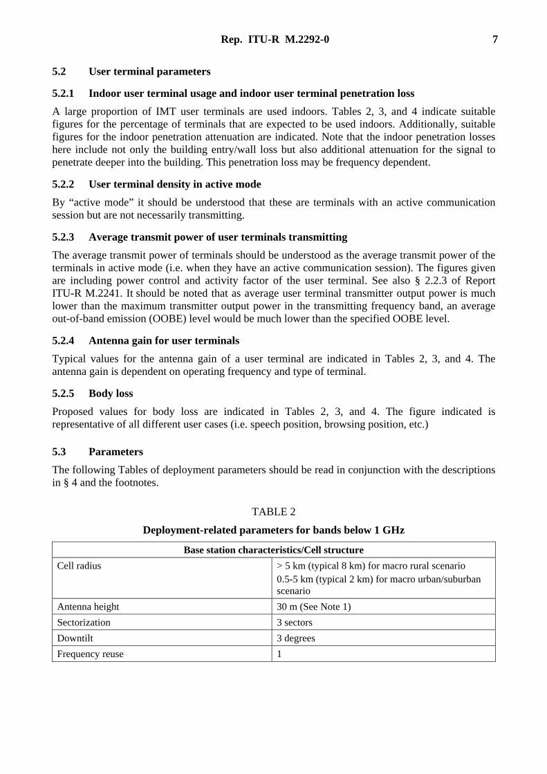
5.2 User terminal parameters
5.2.1 Indoor user terminal usage and indoor user terminal penetration loss
A large proportion of IMT user terminals are used indoors. Tables 2, 3, and 4 indicate suitable figures for the percentage of terminals that are expected to be used indoors. Additionally, suitable figures for the indoor penetration attenuation are indicated. Note that the indoor penetration losses here include not only the building entry/wall loss but also additional attenuation for the signal to penetrate deeper into the building. This penetration loss may be frequency dependent.
5.2.2 User terminal density in active mode
By “active mode” it should be understood that these are terminals with an active communication session but are not necessarily transmitting.
5.2.3 Average transmit power of user terminals transmitting
The average transmit power of terminals should be understood as the average transmit power of the terminals in active mode (i.e. when they have an active communication session). The figures given are including power control and activity factor of the user terminal. See also § 2.2.3 of Report ITU-R M.2241. It should be noted that as average user terminal transmitter output power is much lower than the maximum transmitter output power in the transmitting frequency band, an average out-of-band emission (OOBE) level would be much lower than the specified OOBE level.
5.2.4 Antenna gain for user terminals
Typical values for the antenna gain of a user terminal are indicated in Tables 2, 3, and 4. The antenna gain is dependent on operating frequency and type of terminal.
5.2.5 Body loss
Proposed values for body loss are indicated in Tables 2, 3, and 4. The figure indicated is representative of all different user cases (i.e. speech position, browsing position, etc.)
5.3 Parameters
The following Tables of deployment parameters should be read in conjunction with the descriptions in § 4 and the footnotes.
TABLE 2
Deployment-related parameters for bands below 1 GHz
Base station characteristics/Cell structure
Cell radius > 5 km (typical 8 km) for macro rural scenario 0.5-5 km (typical 2 km) for macro urban/suburban scenario
Antenna height 30 m (See Note 1)
Sectorization 3 sectors
Downtilt 3 degrees
Frequency reuse 1
8 Rep. ITU-R M.2292-0
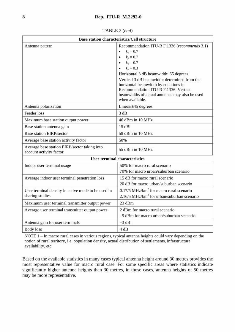
TABLE 2 (end)
Base station characteristics/Cell structure
Antenna pattern Recommendation ITU-R F.1336 (recommends 3.1) • ka = 0.7
• kp = 0.7
• kh = 0.7
• kv = 0.3
Horizontal 3 dB beamwidth: 65 degrees Vertical 3 dB beamwidth: determined from the horizontal beamwidth by equations in Recommendation ITU-R F.1336. Vertical beamwidths of actual antennas may also be used when available.
Antenna polarization Linear/±45 degrees
Feeder loss 3 dB
Maximum base station output power 46 dBm in 10 MHz
Base station antenna gain 15 dBi
Base station EIRP/sector 58 dBm in 10 MHz
Average base station activity factor 50%
Average base station EIRP/sector taking into account activity factor
55 dBm in 10 MHz
User terminal characteristics
Indoor user terminal usage 50% for macro rural scenario 70% for macro urban/suburban scenario
Average indoor user terminal penetration loss 15 dB for macro rural scenario 20 dB for macro urban/suburban scenario
User terminal density in active mode to be used in sharing studies
0.17/5 MHz/km2 for macro rural scenario 2.16/5 MHz/km2 for urban/suburban scenario
Maximum user terminal transmitter output power 23 dBm
Average user terminal transmitter output power 2 dBm for macro rural scenario –9 dBm for macro urban/suburban scenario
Antenna gain for user terminals –3 dBi
Body loss 4 dB
NOTE 1 – In macro rural cases in various regions, typical antenna heights could vary depending on the notion of rural territory, i.e. population density, actual distribution of settlements, infrastructure availability, etc.
Based on the available statistics in many cases typical antenna height around 30 metres provides the most representative value for macro rural case. For some specific areas where statistics indicate significantly higher antenna heights than 30 metres, in those cases, antenna heights of 50 metres may be more representative.
Rep. ITU-R M.2292-0 9
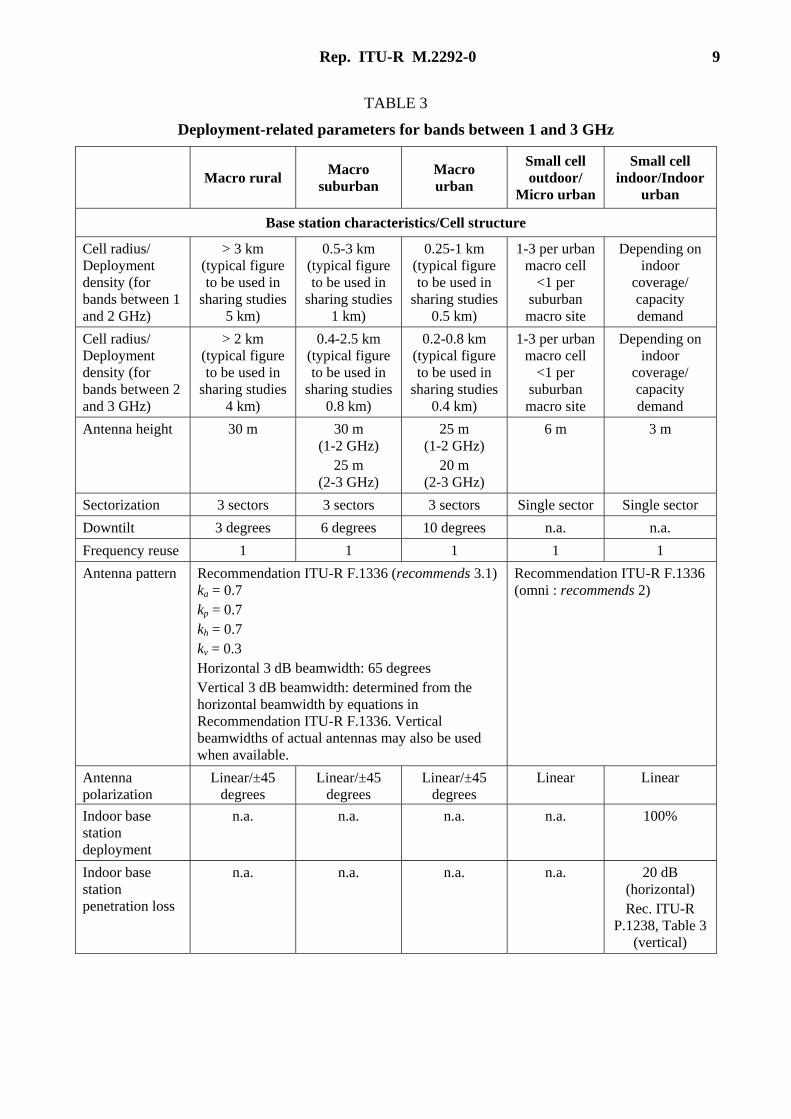
TABLE 3
Deployment-related parameters for bands between 1 and 3 GHz
Macro rural Macro
suburban Macro urban
Small cell outdoor/
Micro urban
Small cell indoor/Indoor
urban
Base station characteristics/Cell structure
Cell radius/ Deployment density (for bands between 1 and 2 GHz)
> 3 km (typical figure to be used in
sharing studies 5 km)
0.5-3 km (typical figure to be used in
sharing studies 1 km)
0.25-1 km (typical figure to be used in
sharing studies 0.5 km)
1-3 per urban macro cell
<1 per suburban macro site
Depending on indoor
coverage/ capacity demand
Cell radius/ Deployment density (for bands between 2 and 3 GHz)
> 2 km (typical figure to be used in
sharing studies 4 km)
0.4-2.5 km (typical figure to be used in
sharing studies 0.8 km)
0.2-0.8 km (typical figure to be used in
sharing studies 0.4 km)
1-3 per urban macro cell
<1 per suburban macro site
Depending on indoor
coverage/ capacity demand
Antenna height 30 m 30 m (1-2 GHz)
25 m (2-3 GHz)
25 m (1-2 GHz)
20 m (2-3 GHz)
6 m 3 m
Sectorization 3 sectors 3 sectors 3 sectors Single sector Single sector
Downtilt 3 degrees 6 degrees 10 degrees n.a. n.a.
Frequency reuse 1 1 1 1 1
Antenna pattern Recommendation ITU-R F.1336 (recommends 3.1) ka = 0.7 kp = 0.7 kh = 0.7 kv = 0.3 Horizontal 3 dB beamwidth: 65 degrees Vertical 3 dB beamwidth: determined from the horizontal beamwidth by equations in Recommendation ITU-R F.1336. Vertical beamwidths of actual antennas may also be used when available.
Recommendation ITU-R F.1336 (omni : recommends 2)
Antenna polarization
Linear/±45 degrees
Linear/±45 degrees
Linear/±45 degrees
Linear Linear
Indoor base station deployment
n.a. n.a. n.a. n.a. 100%
Indoor base station penetration loss
n.a. n.a. n.a. n.a. 20 dB (horizontal) Rec. ITU-R
P.1238, Table 3 (vertical)
10 Rep. ITU-R M.2292-0
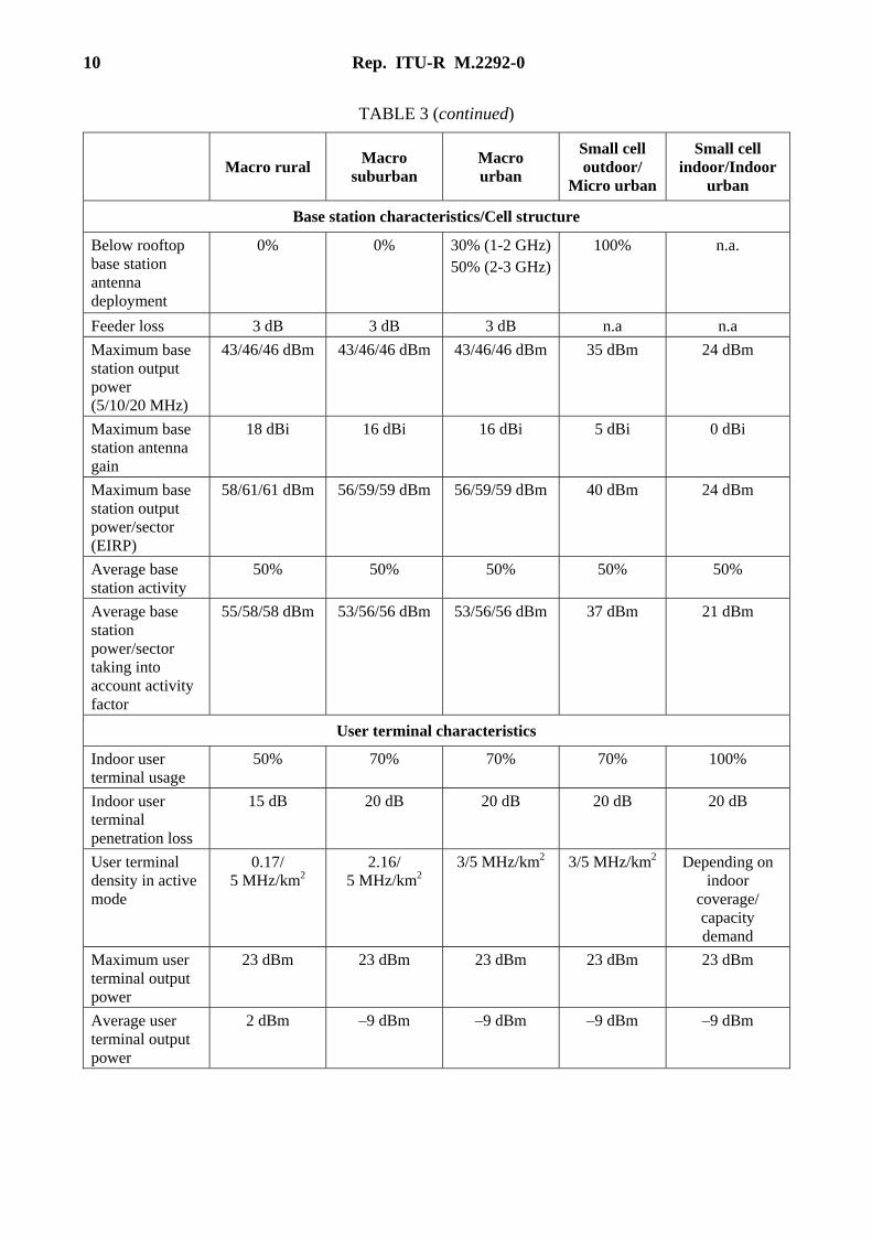
TABLE 3 (continued)
Macro rural Macro
suburban Macro urban
Small cell outdoor/
Micro urban
Small cell indoor/Indoor
urban
Base station characteristics/Cell structure
Below rooftop base station antenna deployment
0% 0% 30% (1-2 GHz) 50% (2-3 GHz)
100% n.a.
Feeder loss 3 dB 3 dB 3 dB n.a n.a
Maximum base station output power (5/10/20 MHz)
43/46/46 dBm 43/46/46 dBm 43/46/46 dBm 35 dBm 24 dBm
Maximum base station antenna gain
18 dBi 16 dBi 16 dBi 5 dBi 0 dBi
Maximum base station output power/sector (EIRP)
58/61/61 dBm 56/59/59 dBm 56/59/59 dBm 40 dBm 24 dBm
Average base station activity
50% 50% 50% 50% 50%
Average base station power/sector taking into account activity factor
55/58/58 dBm 53/56/56 dBm 53/56/56 dBm 37 dBm 21 dBm
User terminal characteristics
Indoor user terminal usage
50% 70% 70% 70% 100%
Indoor user terminal penetration loss
15 dB 20 dB 20 dB 20 dB 20 dB
User terminal density in active mode
0.17/ 5 MHz/km2
2.16/ 5 MHz/km2
3/5 MHz/km2 3/5 MHz/km2 Depending on indoor
coverage/ capacity demand
Maximum user terminal output power
23 dBm 23 dBm 23 dBm 23 dBm 23 dBm
Average user terminal output power
2 dBm –9 dBm –9 dBm –9 dBm –9 dBm
Rep. ITU-R M.2292-0 11
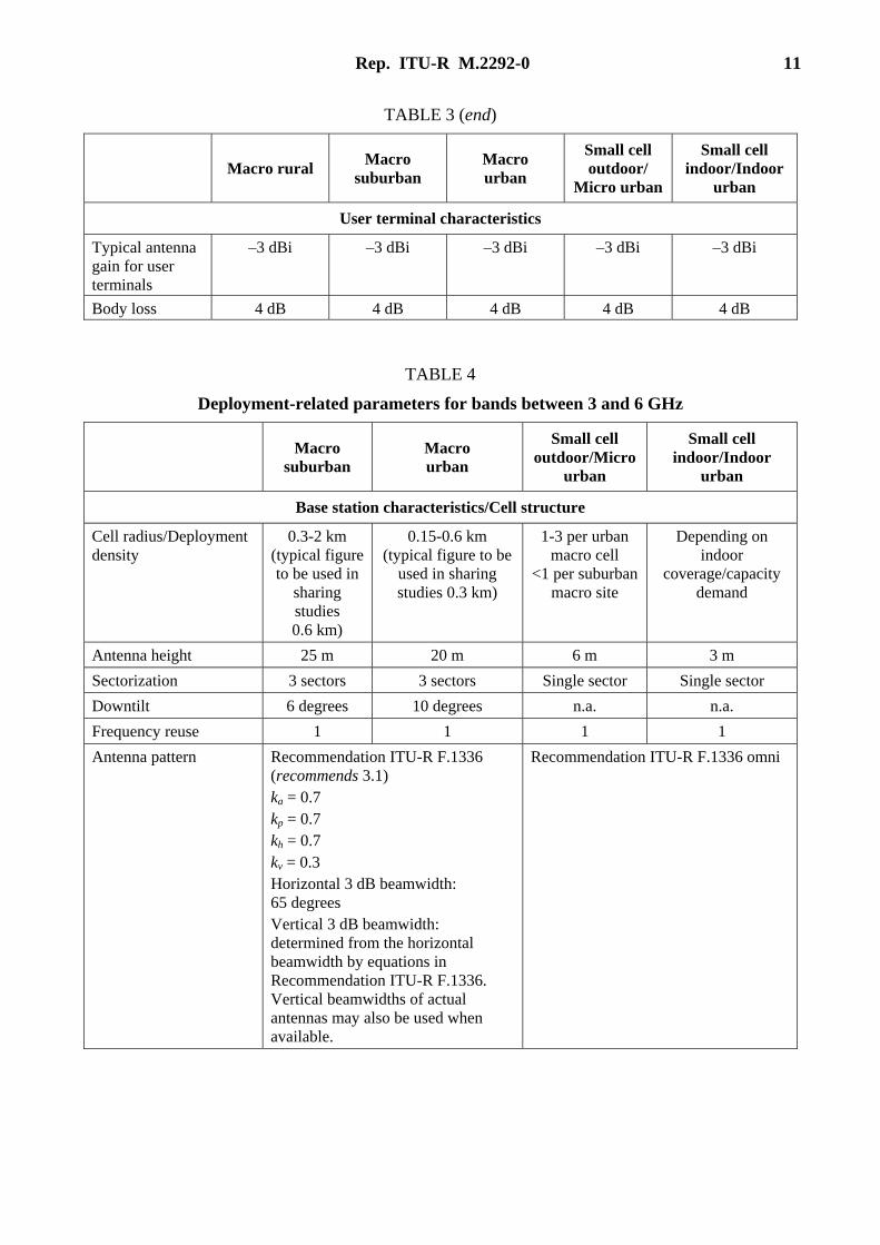
TABLE 3 (end)
Macro rural Macro
suburban Macro urban
Small cell outdoor/
Micro urban
Small cell indoor/Indoor
urban
User terminal characteristics
Typical antenna gain for user terminals
–3 dBi –3 dBi –3 dBi –3 dBi –3 dBi
Body loss 4 dB 4 dB 4 dB 4 dB 4 dB
TABLE 4
Deployment-related parameters for bands between 3 and 6 GHz
Macro
suburban Macro urban
Small cell outdoor/Micro
urban
Small cell indoor/Indoor
urban
Base station characteristics/Cell structure
Cell radius/Deployment density
0.3-2 km (typical figure to be used in
sharing studies 0.6 km)
0.15-0.6 km (typical figure to be
used in sharing studies 0.3 km)
1-3 per urban macro cell
<1 per suburban macro site
Depending on indoor
coverage/capacity demand
Antenna height 25 m 20 m 6 m 3 m
Sectorization 3 sectors 3 sectors Single sector Single sector
Downtilt 6 degrees 10 degrees n.a. n.a.
Frequency reuse 1 1 1 1
Antenna pattern Recommendation ITU-R F.1336 (recommends 3.1) ka = 0.7 kp = 0.7 kh = 0.7 kv = 0.3 Horizontal 3 dB beamwidth: 65 degrees Vertical 3 dB beamwidth: determined from the horizontal beamwidth by equations in Recommendation ITU-R F.1336. Vertical beamwidths of actual antennas may also be used when available.
Recommendation ITU-R F.1336 omni
12 Rep. ITU-R M.2292-0
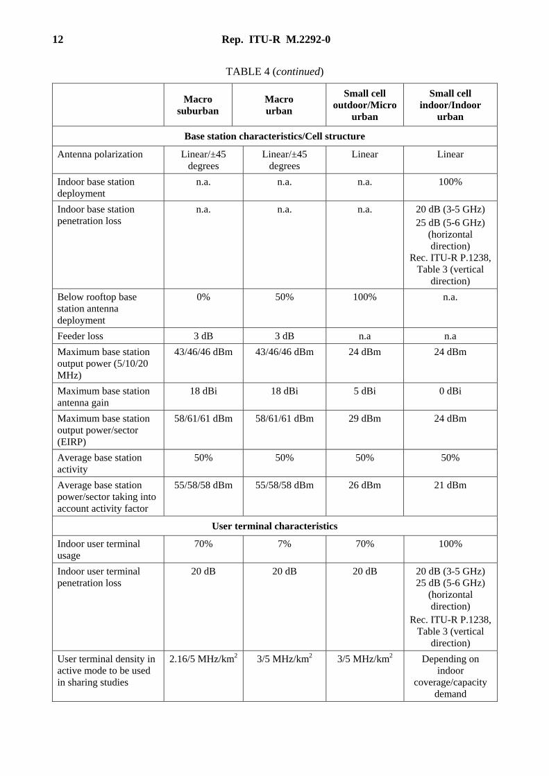
TABLE 4 (continued)
Macro
suburban Macro urban
Small cell outdoor/Micro
urban
Small cell indoor/Indoor
urban
Base station characteristics/Cell structure
Antenna polarization Linear/±45 degrees
Linear/±45 degrees
Linear Linear
Indoor base station deployment
n.a. n.a. n.a. 100%
Indoor base station penetration loss
n.a. n.a. n.a. 20 dB (3-5 GHz) 25 dB (5-6 GHz)
(horizontal direction)
Rec. ITU-R P.1238, Table 3 (vertical
direction)
Below rooftop base station antenna deployment
0% 50% 100% n.a.
Feeder loss 3 dB 3 dB n.a n.a
Maximum base station output power (5/10/20 MHz)
43/46/46 dBm 43/46/46 dBm 24 dBm 24 dBm
Maximum base station antenna gain
18 dBi 18 dBi 5 dBi 0 dBi
Maximum base station output power/sector (EIRP)
58/61/61 dBm 58/61/61 dBm 29 dBm 24 dBm
Average base station activity
50% 50% 50% 50%
Average base station power/sector taking into account activity factor
55/58/58 dBm 55/58/58 dBm 26 dBm 21 dBm
User terminal characteristics
Indoor user terminal usage
70% 7% 70% 100%
Indoor user terminal penetration loss
20 dB 20 dB 20 dB 20 dB (3-5 GHz) 25 dB (5-6 GHz)
(horizontal direction)
Rec. ITU-R P.1238, Table 3 (vertical
direction)
User terminal density in active mode to be used in sharing studies
2.16/5 MHz/km2 3/5 MHz/km2 3/5 MHz/km2 Depending on indoor
coverage/capacity demand
Rep. ITU-R M.2292-0 13
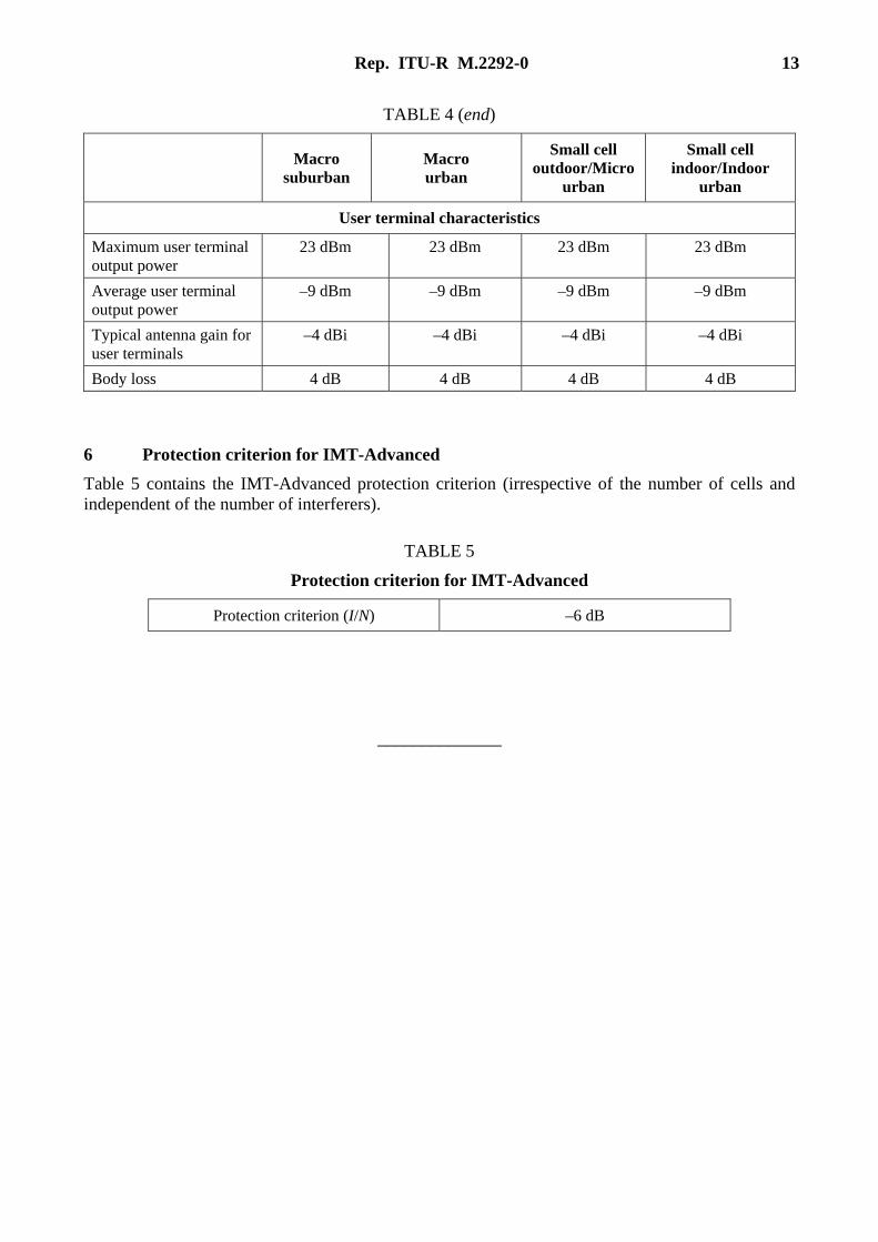
TABLE 4 (end)
Macro
suburban Macro urban
Small cell outdoor/Micro
urban
Small cell indoor/Indoor
urban
User terminal characteristics
Maximum user terminal output power
23 dBm 23 dBm 23 dBm 23 dBm
Average user terminal output power
–9 dBm –9 dBm –9 dBm –9 dBm
Typical antenna gain for user terminals
–4 dBi –4 dBi –4 dBi –4 dBi
Body loss 4 dB 4 dB 4 dB 4 dB
6 Protection criterion for IMT-Advanced
Table 5 contains the IMT-Advanced protection criterion (irrespective of the number of cells and independent of the number of interferers).
TABLE 5
Protection criterion for IMT-Advanced
Protection criterion (I/N) –6 dB
______________