char conversion in fluidized bed indirect gasification · indirect gasification of biomass is a...
TRANSCRIPT
CHAR CONVERSION IN FLUIDIZED BED INDIRECT GASIFICATIONREPORT 2017:393

Char Conversion in Fluidized Bed Indirect Gasification
DAVID PALLARÈS ROBERT JOHANSSON
ANTON LARSSON LOUISE LUNDBERG HENRIK THUNMAN
ISBN 978-91-7673-393-6 | © ENERGIFORSK May 2017
Energiforsk AB | Phone: 08-677 25 30 | E-mail: [email protected] | www.energiforsk.se

CHAR CONVERSION IN FLUIDIZED BED INDIRECT GASIFICATION
3
Foreword
This project brings new knowledge to the phenomenon of char conversion in indirect gasification, a technically proven process which provides highly efficient conversion of biomass and is thus considered a key factor in the phase out of fossil fuels.
The report has been produced by Chalmers University of Technology (CUT) and Göteborg Energi (GE) and the authors are David Pallarès (CUT), Robert Johansson (CUT), Anton Larsson (GE), Louise Lundberg (CUT) and Henrik Thunman (CUT).
The authors would like to acknowledge the Swedish Energy Agency, Energiforsk - Swedish Energy Research Center, for its financial contribution to the project within the scope of the program “Samverkansprogram Energigasteknik” – The cooperation research program Energy gas technology.
This work was also made possible by financial support from Göteborg Energi and has been carried out in collaboration with the Swedish Gasification Center – SFC.
We would also like to thank Valmet for data needed in the process evaluation and Research Institutes of Sweden - RISE for manpower and access to their laboratory reactor.
The authors thank research engineers Rustan Marberg, Jessica Bohwalli and Johannes Öhlin for help during experiments.
Special thanks to Placid Atongka for the assistance in the experimental work at RISE.
Anton Fagerström is acknowledged for his invaluable help in reviewing the report.
The study had a reference/working group with the following members: Ingemar Gunnarsson (Göteborg Energi), Anton Fagerström (Energiforsk), Filip Johnsson (Chalmers University of Technology).

CHAR CONVERSION IN FLUIDIZED BED INDIRECT GASIFICATION
4
Sammanfattning
Indirekt förgasning av biomassa är en tekniskt beprövad process som erbjuder högeffektiv omvandling av biomassa till biogas. Djupare kunskap om koksomvandlingen i förgasningskammaren krävs dock för att på ett pålitligt sätt skala upp processen. Detta projekt tar fram ny kunskap om koksomvandlingen i indirekt förgasning genom att kombinera experiment och modelleringsarbete.
Indirekt förgasning av biomassa förser energisystemet med en högeffektiv termokemisk omvandling av biomassa som kan bidra till att fasa ut fossila bränslen. Processen producerar en biogas som kan ersätta naturgas, omvandlas i gaskombikraftverk, eller förädlas till transportbränsle.
Tekniken bakom indirekt förgasning av biomassa har implementerats på både pilot- och demonstrationsskala, där nyckel-kunskapsbrister har identifierats som behöver åtgärdas för att skala upp processen till kommersiell skala. En särskilt strategisk parameter för att vinna både kunskap och kontroll över processen är graden av koksomvandling i förgasningskammaren, eftersom den har en stark inverkan på värmebalansen och därmed på den totala verkningsgraden för processen. Detta projekt syftar till att, genom en kombination av experiment och modelleringsarbete, få nyckelkunskap om koksomvandlingen i indirekt förgasning samt utveckla en tillförlitlig modell för design och uppskalning av processen.
Experiment har utförts i fyra olika förgasare på laboratorie-, pilot- och demonstrationsskala. Riktade mätkampanjer har utförts i labb-reaktorer samt i Chalmers pilotskaliga system för att studera reaktivitet, förgasningshastighet samt omblandning hos koks. Härav har värden och semi-empiriska uttryck tagits fram för vidare användning i modellen. Mätkampanjer har även genomförts i demonstrationssystemet GoBiGas samt pilotsystemet vid Chalmers i syfte att uppskatta koksomvandlingen i förgasningskammaren hos dessa anläggningar vid olika driftsförhållanden och bränslen.
En modell har utvecklats och validerats som simulerar koksomvandlingen i förgasningskammaren vid indirekt förgasning. Modellen har använts för att studera uppskalningen av processen, där en fin kontroll av partikelcirkulationen i systemet har identifieras som en nyckelfaktor för driftoptimering. En för kort uppehållstid av koks i förgasningskammaren har identifierats som en potentiell begränsning vid uppskalning av processen, och lösningar för att åtgärda detta har föreslagits.

CHAR CONVERSION IN FLUIDIZED BED INDIRECT GASIFICATION
5
Summary
Indirect gasification of biomass is a technically proven process which provides highly efficient conversion of biomass. However, further knowledge on the degree of char conversion in the gasification chamber is needed in order to provide scale-up designs. This project brings new knowledge to the phenomenon of char conversion in indirect gasification systems by combining experimental and modeling work.
Indirect gasification of biomass represents a feasible path for the introduction of highly efficient thermochemical conversion of biomass into the current energy system and thus help to phase out fossil fuels. The process produces a biogas which can substitute natural gas, be used to fuel heat and power plants with a combined cycle, or be further refined into transportation fuel.
Indirect gasification of biomass has been technically proven on both pilot and demonstration scale, from which critical knowledge gaps have been identified that need to be addressed in order to optimize the design and scale-up of the process. A strategic parameter to win both knowledge and control over is the degree of char conversion in the gasification chamber, since this has a strong impact on the heat balance and, thereby, on the overall process efficiency. This project consists of a combination of experimental and modeling work aimed at gaining knowledge on the char conversion in indirect gasification and developing a reliable modeling tool to simulate design and scale-up of the process.
The experimental work has been carried out in four different units at laboratory, pilot and demonstration scale. After identifying a set of critical phenomena to the process (reactivity, gasification rate and mixing of char), dedicated experiments designed to study these and their underlying mechanisms have been executed in laboratory scale reactors and the pilot scale system at Chalmers. From this, values and semi-empirical expressions have been developed for further use in a model. Further, experimental campaigns have been carried out at demonstration (GoBiGas system) and pilot scale (Chalmers system) with the aim to estimate the degree of char conversion in the gasification chamber of these plants under different operational conditions and with different fuels. Besides its high intrinsic value, this data is used for model validation.
A model has been developed which provides satisfactory simulations of the char conversion in the gasification chamber of the two indirect gasification systems included in the project. With this validation, the model is used to study the process scale-up, in which the importance of a fine control of the solids circulation in the system is identified as a key factor for operational optimization. Also, the need of solutions to increase the residence time of the char in the gasification chamber is identified.

CHAR CONVERSION IN FLUIDIZED BED INDIRECT GASIFICATION
6
List of content
1 Aim and Background 7 2 Modeling 9 3 Experiments 11
3.1 Experimental Setups 11 3.1.1 Lab-scale Reactor at RISE 11 3.1.2 Lab-scale Reactor at Chalmers 12 3.1.3 Pilot-scale System at Chalmers 14 3.1.4 Demonstration-scale System at GoBiGas 15
3.2 Measurements 17 3.2.1 Lateral Mixing of Char 17 3.2.2 Rate of Char Gasification 19 3.2.3 Degree of Char Gasification 24
4 Results 27 4.1 Model Validation 27 4.2 Chalmers and GoBiGas systems 27 4.3 Process Optimization and scale-up 30
5 Assessment of Aim Achievement 34 6 Publications 36
7 References 37

CHAR CONVERSION IN FLUIDIZED BED INDIRECT GASIFICATION
7
1 Aim and Background
The use of biomass for production of biofuels has attracted strong interest as it represents a means for both decreasing CO2 emissions and ending the dependence on fossil fuels. With this route being strongly reliant on the availability of a biomass source and Sweden being a biomass-rich country, ambitious goals have been set at a national level which are summarized to no net emissions of greenhouse gases by 2050 and a fossil-free vehicle fleet by 2030 [1].
Biomass gasification provides a thermochemical conversion route with higher efficiency (up to ~75%, depending on the gasification technology used) than that reachable through biomass combustion (~40%). Recently, indirect gasification has been recognized as a viable alternative for the production of biogas with high enough quality to be used, after some upgrading, as biofuel in substitution of fossil fuels. Demonstration-scale projects with technical success have been carried out in CHP plants in Austria (Güssing and Oberwart) and Germany (Senden), and in GoBiGas, the SNG-plant in Göteborg.
Indirect gasification uses a Dual Fluidized Bed (DFB) system (Fig. 1) consisting of two intercoupled fluidized bed reactors – one combustor and one gasifier - between which a considerable amount of bed material is circulated. This circulating bed material acts as a heat carrier from the combustor to the gasifier, thus satisfying the net energy demand in the gasifier originated by the fact that it is fluidized solely with steam, i.e. with no air/oxygen present, in contrast to the classical approach in gasification technology also called direct gasification. The absence of nitrogen and combustion in the gasifying chamber implies the generation of a raw gas with much higher heating value than that in direct gasification. The char which is not converted in the gasifying chamber follows the circulating bed material into the combustor, which is fluidized with air, where it is combusted and releases heat which is captured by the circulating bed material and thereby transported into the gasifier in order to close the heat balance of the system.
Figure 1: Principle of indirect gasification (in this case, with raw gas recirculation)

CHAR CONVERSION IN FLUIDIZED BED INDIRECT GASIFICATION
8
For a given indirect gasification system, fuel and operational conditions, one optimal extent of char conversion in the gasifier exists which maximizes the process efficiency. The optimal degree of char conversion within the gasification chamber, XCH,opt, depends on factors such as the composition of the feedstock, the desired end-product, and temperatures and magnitudes of the gas flows fed into the unit. It typically lies within the interval 10–50% (see [2] for a deeper study on this parameter). Thus, it becomes obvious that it is crucial to control the extent of char conversion in the gasifier in order to optimize the system performance. For this, better knowledge on the factors and mechanisms governing char conversion in the gasifier is needed. The following goals were defined for the present project:
Impact goal
To bring indirect gasification technology closer to commercialization by improving the generic knowledge of char conversion in indirect gasification, developing models that can determine the char conversion in systems of different scale and can be used in the design of the process.
Project goals
P1) To develop general knowledge of the factors and mechanisms by which char conversion is governed in indirect gasification plants. Such knowledge is of great importance for the design, control and scale-up of the process.
P2) To determine the kinetical data for fuels that are relevant to the GoBiGas project. For this purpose, a laboratory reactor with access to raw gas from the Chalmers process is to be built which can be used to study individual mechanisms in char conversion, such as kinetics and interactions with the bed material.
P3) To produce validation data for the char conversion in the Chalmers and GoBiGas systems. Data provides knowledge of how mixing phenomena affect char conversion and provides a basis for generalizing the understanding of char conversion.
P4) To develop models that describe char conversion in the various plants, taking into account the different mechanisms for mixing and kinetics. These models, based on tests at laboratory and large scales, gather knowledge about char conversion and are general in the sense that can be used as a tool for developing the process.
The methodology used is based in using the model as a knowledge repository which is constantly updated with new findings and is used to identify critical knowledge gaps which need to be addressed experimentally through dedicated measurement campaigns. Finally, a model results which contains the knowledge attained and can be used as a tool for process development (design, scale-up and optimization).
The scope is limited to gasifying chambers operating at bubbling conditions, i.e. the solids circulation is governed by the operational conditions in the combustion reactor, which is a circulating fluidized bed. This combination (a bubbling gasifier and a circulating combustor) is generally considered the optimal solution for indirect gasification [3], as the solids circulation can be controlled while still keeping the fluidization velocity in the gasifier as a further process control parameter.

CHAR CONVERSION IN FLUIDIZED BED INDIRECT GASIFICATION
9
2 Modeling
The present work uses semi-empirical modelling, i.e. velocity fields are not solved from the momentum transfer equations but obtained by simpler means detailed below. This is a widely used approach to mathematically describe fluidized bed reactors (see e.g. [4-6]), as it provides reliable and resolved results to an affordable computational cost. A 3D and a 1D version of the model are implemented. In the 1D version of the model, the domain is discretized laterally, in the direction of the solids crossflow across the gasifying chamber. The 3D version is restricted to reactor geometries with rectangular cross section.
The model considers a certain number of gas species (typically CO, CO2, H2, H2O, CH4, and tars - represented by C6H6O), i. The fuel is divided into four components, k: moisture, volatiles, char and ash. Each of these can be divided into a number of conversion classes j≥1 in order to account for conversion rates which vary as conversion occurs. The model solves the mass and heat balances formulated below.
Mass balance in bubble phase of each gas species i:
𝜕𝜕�𝜌𝜌𝑢𝑢��⃑ 𝑏𝑏𝑤𝑤𝑏𝑏,𝑖𝑖�𝜕𝜕𝑟𝑟
= �̇�𝑟ℎ𝑜𝑜𝑜𝑜,𝑏𝑏,𝑖𝑖′′′ + 𝜌𝜌𝛿𝛿𝑏𝑏𝐾𝐾𝑏𝑏𝑏𝑏�𝑤𝑤𝑏𝑏,𝑖𝑖 − 𝑤𝑤𝑏𝑏,𝑖𝑖� (1)
Mass balance in emulsion phase of each gas species i:
𝜕𝜕�𝜌𝜌𝑢𝑢��⃑ 𝑒𝑒𝑤𝑤𝑒𝑒,𝑖𝑖�𝜕𝜕𝑟𝑟
= 𝜕𝜕𝜕𝜕𝑟𝑟�𝜌𝜌𝐷𝐷𝑔𝑔
𝜕𝜕𝑤𝑤𝑒𝑒,𝑖𝑖𝜕𝜕𝑟𝑟
� + �̇�𝑟ℎ𝑜𝑜𝑜𝑜,𝑏𝑏,𝑖𝑖′′′ + �̇�𝑟ℎ𝑏𝑏𝑒𝑒,𝑏𝑏,𝑖𝑖
′′′ − 𝜌𝜌𝛿𝛿𝑏𝑏𝐾𝐾𝑏𝑏𝑏𝑏�𝑤𝑤𝑏𝑏,𝑖𝑖 − 𝑤𝑤𝑏𝑏,𝑖𝑖� (2)
Mass balance of class j in fuel component k (population balance):
𝜕𝜕�𝑢𝑢��⃑ 𝑘𝑘,𝑗𝑗𝑐𝑐𝑘𝑘,𝑗𝑗�𝜕𝜕𝑟𝑟
= 𝜕𝜕𝜕𝜕𝑟𝑟�𝐷𝐷𝑘𝑘,𝑗𝑗
𝜕𝜕𝑐𝑐𝑘𝑘,𝑗𝑗
𝜕𝜕𝑟𝑟� + �̇�𝑚𝑘𝑘,𝑗𝑗
′′′ (3)
Potential flow model for the velocity field of gas and of bulk solids:
0 = 𝜕𝜕2𝛷𝛷𝜕𝜕𝑟𝑟2
+ 𝑆𝑆𝑔𝑔𝑏𝑏𝑔𝑔 (4) , and 𝑢𝑢�⃑ = 1𝜌𝜌𝜕𝜕𝛷𝛷𝜕𝜕𝑟𝑟
(5)
Velocity field of class j in fuel component k:
𝑢𝑢�⃑ 𝑘𝑘,𝑗𝑗 = �̿�𝜃𝑘𝑘,𝑗𝑗𝑢𝑢�⃑ 𝑠𝑠 (6)
Heat balance:
𝜕𝜕�∑ 𝑢𝑢��⃑ 𝑚𝑚𝑐𝑐𝑚𝑚𝐶𝐶𝑝𝑝,𝑚𝑚𝑇𝑇𝑚𝑚 �𝜕𝜕𝑟𝑟
= 𝜕𝜕𝜕𝜕𝑟𝑟𝑘𝑘 𝜕𝜕𝑇𝑇𝜕𝜕𝑟𝑟
+ ∑ �̇�𝑚𝑟𝑟′′′∆ℎ𝑟𝑟𝑟𝑟 (7)
For the mass balance of a gas species in the bubble phase, note the absence of both heterogeneous reactions and dispersive transport (in contrast to the mass balance in the emulsion phase gas), while the last term represents the exchange between bubble gas and emulsion gas (see [7] for details on the classical two-phase flow theory). The velocity fields for the bulk solids and the gas phases are calculated through the assumption of a potential flow, where the source term is zero for the solids case while for the case of the gas it includes gas compression or expansion

CHAR CONVERSION IN FLUIDIZED BED INDIRECT GASIFICATION
10
due to reactions which are non-equimolar in gaseous components. Finally, note that the velocity of the fuel is described as a fraction (given by the so-called impact factor, θ) of that of the bulk solids.
Solid fuel conversion in fluidized beds is often modelled with the use of population balances, where the conversion process of a fuel component is divided into a number of classes (typically based on fuel particle size). Different methods for the discretization of a fuel component into classes have been investigated within the framework of this project, as well as the number of classes necessary to yield a satisfactory accuracy. Finally, a discretization method which defines classes based on the conversion degree (rather than size or density) and that is generally valid for all conversion regimes (shrinking core, shrinking density, hybrid), is proposed in [8] (details of the method are not given in this report). The results show that application of the class division method developed gives, at a given computational cost, an accuracy up to ten times higher than that given by classical methods. Further, results show that for indirect biomass gasification the use of six classes defined with the new method developed is sufficient to yield an error level around 1%, which implies a highly significant saving in computational time, especially for the 3-dimensional runs.
Having the model formulation expressed in Eqs 1 to 7 above, values or expressions for the semi-empirical parameters used are required. These can be found in literature or derived from dedicated experimental campaigns. In order to make a decision on which parameters are critical for the specific process in study, a set of sensitivity analyses has to be carried out which includes case simulations at different scales. From this, the following two semi-empirical parameters were identified as critical to the determination of the extent of char conversion in indirect gasification of biomass:
• Horizontal dispersion coefficient of biomass (Dk,j in Eq. 3) • Rate of char gasification (�̇�𝑚𝑘𝑘,𝑗𝑗
′′′ in Eq. 3)
Measurement campaigns dedicated to develop expressions for these two parameters have represented a significant part of the experimental work in this project, and are summarized in Sections 3.2.1 and 3.2.2, respectively. There was a big lack in literature regarding the horizontal dispersion coefficient of biomass at operational conditions relevant for indirect gasification, i.e. hot conditions and presence of a significant solids crossflow. In contrast, there is abundant data regarding char gasification kinetics, but the char kinetics of the specific fuel used needed to be determined. Furthermore, the influence on char kinetics and char gasification rate of variations in the surrounding conditions relevant for indirect gasification (use of inert/active bed material, flotsam/non-flotsam biomass) was not studied in literature and needed to be studied in order to formulate a model which is reliable over a relevant span of operational conditions.
As for the rest of semi-empirical parameters in the model equations, values and expressions were found in the literature (see [9] for the details).

CHAR CONVERSION IN FLUIDIZED BED INDIRECT GASIFICATION
11
3 Experiments
Experimental data has been generated in order to provide empirical input to the tasks of model development (lateral mixing of biomass, char gasification kinetics) and model validation (char conversion in the gasification chamber). The experimental setups and campaigns used in this project are presented below.
3.1 EXPERIMENTAL SETUPS
Four experimental setups ranging from laboratory to demonstration scale have been used in the project.
3.1.1 Lab-scale Reactor at RISE
A laboratory scale bubbling fluidized bed reactor owned by RISE and located in Borås was used to carry out studies on the char kinetics while the laboratory facility at Chalmers was not ready yet. A schematic of the experimental setup is shown in Fig. 2. The inner diameter of the reactor is 7 cm and its total height is 140 cm. Distilled water (1) is transported at a controlled rate by a water pump (2) to a steam generator (3). The bed can be fluidized with any mix of nitrogen and steam set using mass flow regulators (4) and the gases are preheated in the 60 cm high preheating zone (5) before entering the reactor through a perforated ceramic plate (6), above which the fluidized bed (7) is located.
Figure 2: Schematic of the laboratory scale facility located at RISE

CHAR CONVERSION IN FLUIDIZED BED INDIRECT GASIFICATION
12
A silica sand bed with a height of approximately 4 cm is used. The reactor (see Fig. 3) is electrically heated by heating elements (8) on the reactor walls. A K-type thermocouple inserted into the bed of the reactor is used to measure the bed temperature, which is controlled by a temperature regulator connected to the heating elements on the reactor walls.
Figure 3: Laboratory scale reactor at RISE
Fuel particles are inserted at the top of the reactor (9). A gas probe (10) is used to sample a slip stream while the rest of the gases generated enter the exhaust hood (11). The sampled gases are transferred through a particle filter (12) with the aid of a gas pump (13). The gases then pass through a condenser where the steam and tars are condensed (14) before reaching the gas analyzers (15) which measure the concentrations of CO, CO2 and O2. Finally the output from the gas analyzers is transformed using a pc logger (16) and the data is logged on a computer (17) every fifth second.
3.1.2 Lab-scale Reactor at Chalmers
A laboratory scale bubbling fluidized bed reactor located at Chalmers was built to carry out studies on the char kinetics. A schematic of the gas feeding system, which
CHAR CONVERSION IN FLUIDIZED BED INDIRECT GASIFICATION
13
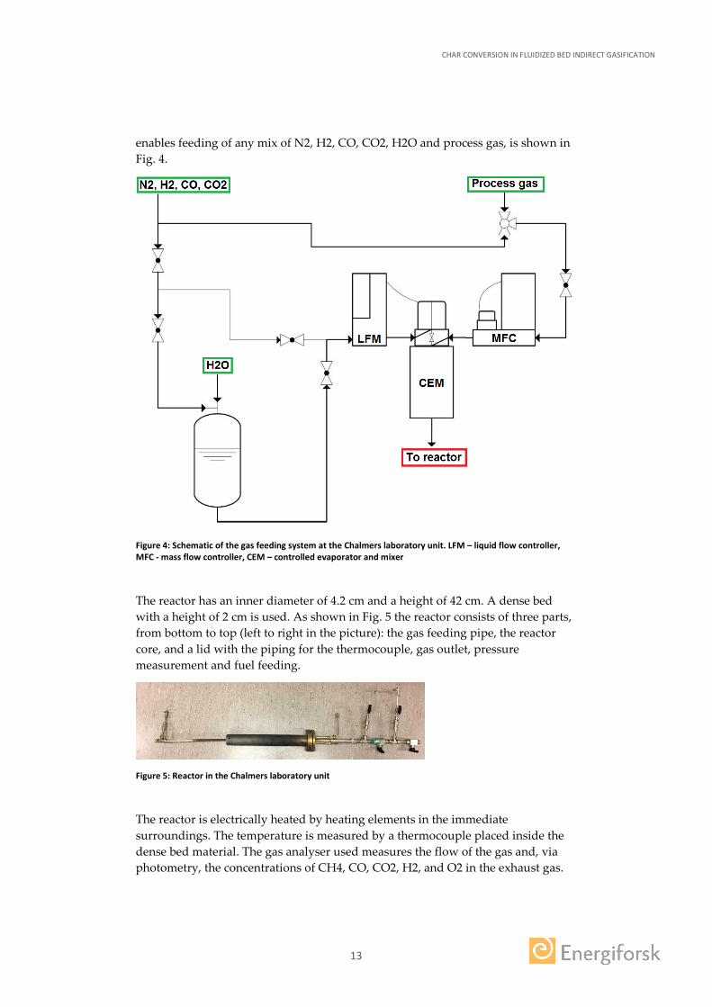
enables feeding of any mix of N2, H2, CO, CO2, H2O and process gas, is shown in Fig. 4.
Figure 4: Schematic of the gas feeding system at the Chalmers laboratory unit. LFM – liquid flow controller, MFC - mass flow controller, CEM – controlled evaporator and mixer
The reactor has an inner diameter of 4.2 cm and a height of 42 cm. A dense bed with a height of 2 cm is used. As shown in Fig. 5 the reactor consists of three parts, from bottom to top (left to right in the picture): the gas feeding pipe, the reactor core, and a lid with the piping for the thermocouple, gas outlet, pressure measurement and fuel feeding.
Figure 5: Reactor in the Chalmers laboratory unit
The reactor is electrically heated by heating elements in the immediate surroundings. The temperature is measured by a thermocouple placed inside the dense bed material. The gas analyser used measures the flow of the gas and, via photometry, the concentrations of CH4, CO, CO2, H2, and O2 in the exhaust gas.

CHAR CONVERSION IN FLUIDIZED BED INDIRECT GASIFICATION
14
3.1.3 Pilot-scale System at Chalmers
The Chalmers pilot scale indirect gasification system consists of a 2.4-MWth bubbling fluidized bed gasifier connected to the previously existing 12-MWth circulating fluidized bed boiler (see Fig. 6). During standard operation a fuel flow of roughly 400kg/h is fed to the gasifier.
Figure 6: Schematic of the Chalmers indirect gasification system
CHAR CONVERSION IN FLUIDIZED BED INDIRECT GASIFICATION
15
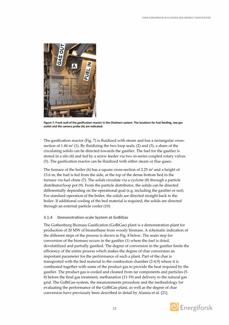
Figure 7: Front wall of the gasification reactor in the Chalmers system. The locations for fuel feeding, raw gas outlet and the camera probe (A) are indicated.
The gasification reactor (Fig. 7) is fluidized with steam and has a rectangular cross-section of 1.44 m2 (1). By fluidizing the two loop seals, (2) and (3), a share of the circulating solids can be directed towards the gasifier. The fuel for the gasifier is stored in a silo (4) and fed by a screw feeder via two in-series coupled rotary valves (5). The gasification reactor can be fluidized with either steam or flue gases.
The furnace of the boiler (6) has a square cross-section of 2.25 m2 and a height of 13.6 m; the fuel is fed from the side, at the top of the dense bottom bed in the furnace via fuel chute (7). The solids circulate via a cyclone (8) through a particle distributor/loop pot (9). From the particle distributor, the solids can be directed differentially depending on the operational goal (e.g. including the gasifier or not). For standard operation of the boiler, the solids are directed straight back to the boiler. If additional cooling of the bed material is required, the solids are directed through an external particle cooler (10).
3.1.4 Demonstration-scale System at GoBiGas
The Gothenburg Biomass Gasification (GoBiGas) plant is a demonstration plant for production of 20 MW of biomethane from woody biomass. A schematic indication of the different steps of the process is shown in Fig. 8 below. The main step for conversion of the biomass occurs in the gasifier (1) where the fuel is dried, devolatilized and partially gasified. The degree of conversion in the gasifier limits the efficiency of the entire process which makes the degree of char conversion an important parameter for the performance of such a plant. Part of the char is transported with the bed material to the combustion chamber (2-4,9) where it is combusted together with some of the product gas to provide the heat required by the gasifier. The product gas is cooled and cleaned from tar components and particles (5-8) before the final gas treatment, methanation (11-19) and delivery to the natural gas grid. The GoBiGas-system, the measurements procedure and the methodology for evaluating the performance of the GoBiGas plant, as well as the degree of char conversion have previously been described in detail by Alamia et al. [21].

CHAR CONVERSION IN FLUIDIZED BED INDIRECT GASIFICATION
16
Figure 8 - Process schematic of the GoBiGas biomass to biomethane plant: 1. gasifier; 2, combustion chamber; 3, cyclone; 4, post-combustion chamber; 5, raw gas cooler; 6, raw gas filter; 7 RME scrubber; 8, carbon beds; 9, flue gas train; 10, fuel feeding system; 11, product gas compressor; 12, hydration of olefins and COS; 13, H2S removal; 14, guard bed; 15, water-gas shift reactor; 16, pre-methanation; 17, CO2 removal, 18 methanation; 19, drying.
CHAR CONVERSION IN FLUIDIZED BED INDIRECT GASIFICATION
17
3.2 MEASUREMENTS
Measurement campaigns were carried out in the experimental setups specified above. These campaigns were intended to empirically assess critical parameters in the model formulation and to generate experimental points for the later model validation.
3.2.1 Lateral Mixing of Char
The lateral mixing of char was identified through model simulations as a parameter critically influencing the char conversion in the gasification chamber. An experimental campaign was planned in the Chalmers gasifier with the goal to investigate the lateral mixing of solid fuel at hot conditions in the presence of a significant solids crossflow, as no data on this previously existed in literature. More detailed information beyond the summary given in this report can be found in [10, 11].
A camera probe was used to record videos of the bed surface and these videos were subsequently analyzed with a computer in order to extract information on the lateral movement of the biomass particles. The camera probe is equipped with a cooling jacket which allows for water cooling. Since the ceramic glass cannot withstand temperatures higher than 800 °C (higher temperatures can lead to cracking of the glass), it is purged with nitrogen gas in order to maintain the temperature of the glass below the critical temperature of 800 °C and to keep the glass free from bed material and condensable gases. A special front glass able to reflect a large fraction of the incoming infrared radiation was chosen in order to prevent overheating of the camera inside the probe.
During the experiments biomass is fed continuously to the gasifier at a rate of 200 kg/h and a bed temperature of 800 °C, under the presence of a solids circulation varying from 0 to 8.6 kg/s. Experiments were also carried out in the absence of a solids crossflow in order to evaluate its influence on the lateral mixing of biomass.
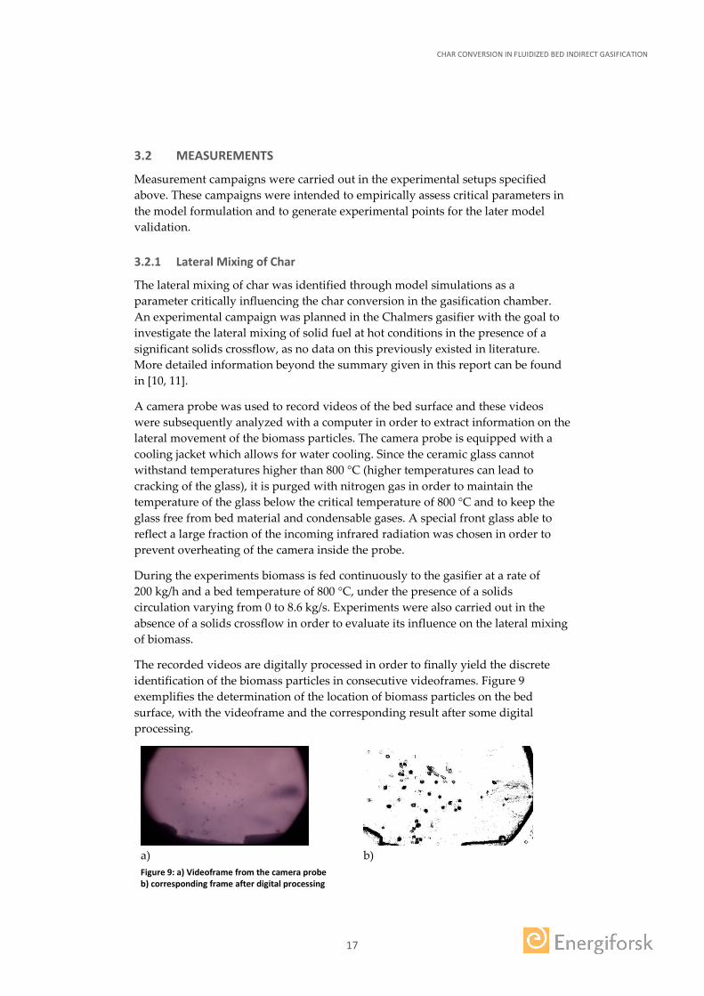
The recorded videos are digitally processed in order to finally yield the discrete identification of the biomass particles in consecutive videoframes. Figure 9 exemplifies the determination of the location of biomass particles on the bed surface, with the videoframe and the corresponding result after some digital processing.
a)
b)
Figure 9: a) Videoframe from the camera probe b) corresponding frame after digital processing
CHAR CONVERSION IN FLUIDIZED BED INDIRECT GASIFICATION
18
From this, the distribution of biomass particle velocities can be determined. As the dispersive contribution to the lateral mixing of biomass in a fluidized bed is stochastic, it can be described on the mesoscopic scale through equations for Brownian motion at microscale. Thus, applying Einstein’s equation for Brownian motion:
𝐷𝐷 = (∆𝑥𝑥)2
2∆𝑒𝑒 (8)
where the time step is the inverse of the frame rate (1/25) and the displacement between consecutive frames, Δx, is provided by the digital image analysis.
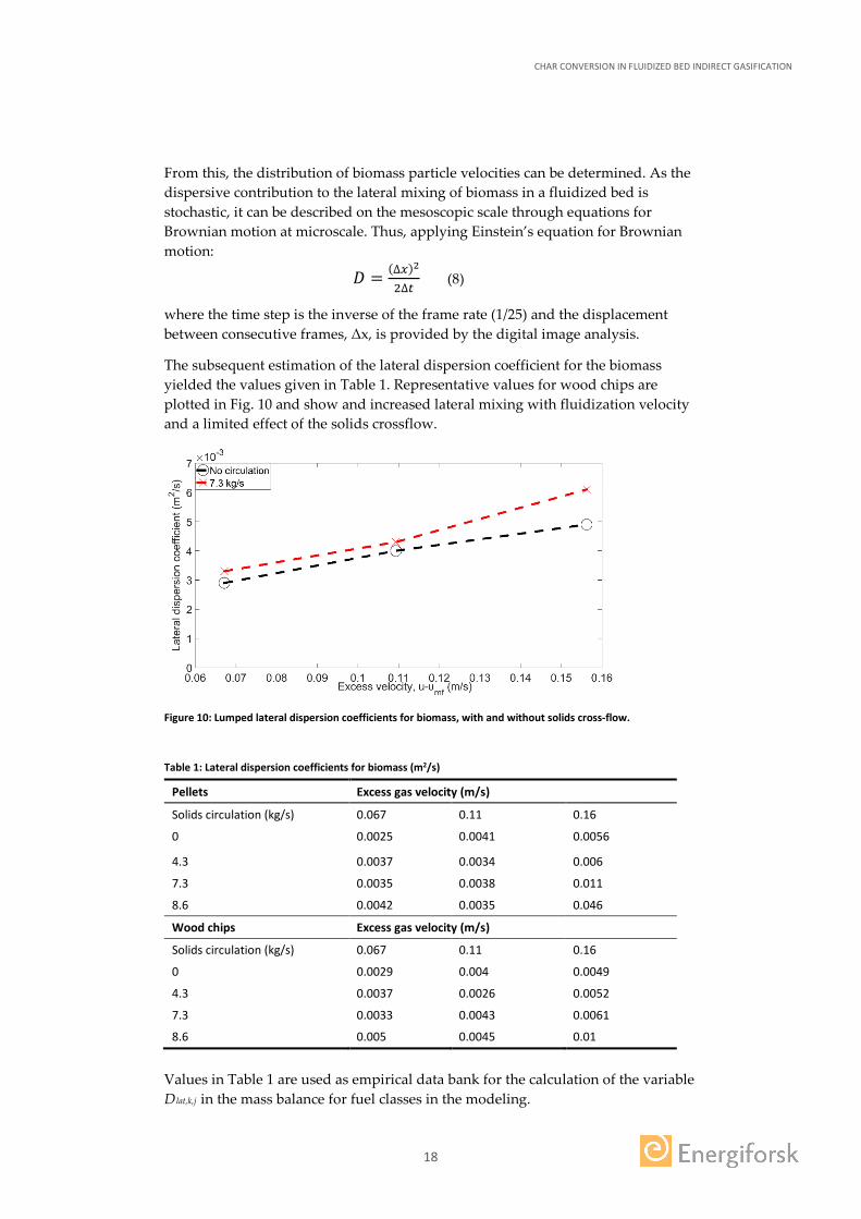
The subsequent estimation of the lateral dispersion coefficient for the biomass yielded the values given in Table 1. Representative values for wood chips are plotted in Fig. 10 and show and increased lateral mixing with fluidization velocity and a limited effect of the solids crossflow.
Figure 10: Lumped lateral dispersion coefficients for biomass, with and without solids cross-flow.
Table 1: Lateral dispersion coefficients for biomass (m2/s)
Pellets Excess gas velocity (m/s)
Solids circulation (kg/s) 0.067 0.11 0.16
0 0.0025 0.0041 0.0056
4.3 0.0037 0.0034 0.006
7.3 0.0035 0.0038 0.011
8.6 0.0042 0.0035 0.046
Wood chips Excess gas velocity (m/s)
Solids circulation (kg/s) 0.067 0.11 0.16
0 0.0029 0.004 0.0049
4.3 0.0037 0.0026 0.0052
7.3 0.0033 0.0043 0.0061
8.6 0.005 0.0045 0.01
Values in Table 1 are used as empirical data bank for the calculation of the variable Dlat,k,j in the mass balance for fuel classes in the modeling.

CHAR CONVERSION IN FLUIDIZED BED INDIRECT GASIFICATION
19
3.2.2 Rate of Char Gasification
The rate of char gasification has also been identified as a critical parameter for the correct estimation of the extent of gasification in an indirect gasification system.
As char kinetics are known to be strongly fuel-specific, experiments have been carried out in order to determine the kinetical parameters under reference conditions of the specific biomass used at the Chalmers and GoBiGas systems.
However, the char kinetics may be affected by other factors such as the axial location of the biomass particle during drying and devolatilization, which has also been studied within the framework of this project.
Finally, with given char kinetics, the reaction rate may be affected by the presence of active bed material in the surroundings, which has also been studied.
Determination of the char kinetics of the reference biomass
The laboratory reactor at RISE was used to investigate the char gasification kinetics from the reference biomass used at the GoBiGas and the Chalmers indirect gasification systems (wood pellets with a diameter of 8 mm and lengths ranging between 13 and 20 mm). More detailed information about this work beyond the summary given below can be found in [12].
Pure N2 was used for fluidizing to allow pyrolysis to occur, after which a mixture of steam and nitrogen (see Table 2) was injected to allow char gasification at a fluidization velocity of 0.35 m/s. After a given retention time (15-25 minutes) the experiment was terminated and air was used to combust any remaining char, while still monitoring the CO and CO2 concentrations to allow closure of the carbon balance (Table 2). In two cases (Experiments 1 and 7) it was not possible to calculate the carbon balance due to overheating of the O2 analyzer at the end of the experiments. Nine experiments were conducted at different temperatures (758-875ºC) and steam concentrations (58-89%vol), see Table 2.
Table 2. Experimental matrix.
Experiment Temperature [ºC] Steam concentration [%vol]
Char gasification test time [min]
Accuracy in carbon balance [%]
1 856 89 20 -
2 854 69 24 98.0
3 855 58 15 100.1
4 758 89 22 100.9
5 774 89 22 97.0
6 802 89 22 101.4
7 819 89 20 -
8 875 89 20 96.4
9 840 72 25 102.1

CHAR CONVERSION IN FLUIDIZED BED INDIRECT GASIFICATION
20
Time-averaged char conversion rates for the first 15 minutes of the nine experiments are presented in Fig. 11. The reactivity increases with temperature as expected. However, the steam concentration does not significantly affect the reactivity; at 855 ºC the reactivity is essentially the same for the three steam concentrations investigated.
Figure 11. Average normalized char gasification rates during the first 15 minutes
The degree of char conversion, X, is defined as:
𝑋𝑋(𝑡𝑡) = 𝑜𝑜0−𝑜𝑜(𝑒𝑒)𝑜𝑜0
(9)
The normalized rate of char gasification, 𝑅𝑅𝑜𝑜, can be expressed as [13]:
𝑅𝑅𝑜𝑜 = 𝑑𝑑𝑑𝑑(𝑒𝑒)𝑑𝑑𝑒𝑒
= 𝑅𝑅�𝑇𝑇,𝑃𝑃𝐻𝐻2𝑂𝑂�𝑓𝑓(𝑋𝑋) (10)
Where R, assuming nth order kinetics, is expressed as:
𝑅𝑅�𝑇𝑇,𝑃𝑃𝐻𝐻2𝑂𝑂� = 𝑘𝑘0𝑒𝑒−𝐸𝐸𝑎𝑎𝑅𝑅𝑅𝑅 𝑃𝑃𝐻𝐻2𝑂𝑂
𝑔𝑔 (11)
Note that 𝑓𝑓(𝑋𝑋) describes how changes in the char structure during the conversion process influence the char reactivity. Of the different models proposed to describe this effect, two are commonly used: the grain model [14] and the random pore model [15]. Nilsson et al.[16] found that none of these models gave a satisfactory fit with their experimental results and suggested an empirical model. Expressions for 𝑓𝑓(𝑋𝑋) in each of the three approaches are given in Table 3.
Table 3. Models used to describe how the conversion rate depends on the degree of conversion.
Model f(X) Parameters
Grain model (GM) (1 − 𝑋𝑋)2/3 -
Random pore model (RPM) (1 − 𝑋𝑋)�1 −Ψln(1 − 𝑋𝑋) Ψ
Empirical model (EM) (1 − 𝑋𝑋) (𝑎𝑎𝑋𝑋 + 𝑏𝑏)𝑒𝑒𝑒𝑒𝑒𝑒 (−𝑐𝑐𝑋𝑋𝑑𝑑) a, b, c, d
Table 4 shows the kinetical parameters obtained from the tests.
Table 4. Kinetic parameters for reference biomass
𝒌𝒌𝟎𝟎 [𝒃𝒃𝒃𝒃𝒃𝒃−𝟎𝟎.𝟏𝟏𝒔𝒔−𝟏𝟏] 𝑬𝑬𝒃𝒃 [𝒌𝒌𝒌𝒌/𝒎𝒎𝒎𝒎𝒎𝒎/𝑲𝑲] 𝒏𝒏 [−]
7234.5 148.3 0.4

CHAR CONVERSION IN FLUIDIZED BED INDIRECT GASIFICATION
21
The dependence of the reactivity on the degree of char conversion was adjusted for the three models specified above, yielding the values in Table 5, and used to simulate the char gasification process and compare to the measured one, as seen in Fig. 12.
Table 5. Fitted parameters for the random pore model and the empirical model.
𝚿𝚿 [−] 𝒃𝒃 [−] 𝒃𝒃 [−] 𝒄𝒄 [−] 𝒅𝒅 [−]
3.602 2.096 ∙ 105 1.817 ∙ 105 12.63 0.05064
Figure 12. Experimental and modelled conversion rates as a function of time for experiment 4 comparing the three different structural models f(X).
As seen from Fig. 12, the empirical model is the only one which gives a satisfactory agreement with the experimental data obtained in the lab unit.
Influence of the axial segregation on the char kinetics
The experiments were carried out in the laboratory reactor located at RISE with the same procedure as for the tests determining the kinetics of the reference biomass. The difference here was that a wire-mesh basket with a lid was used to control the position of the fuel during pyrolysis and char gasification. The position of the basket can be adjusted during the course of an experiment. Flue gas analysis was used to close the carbon balance and determine the char gasification rate in each run. More detailed information beyond the summary given below can be found in [17].
The experimental matrix is presented in Table 6. Two different types of experiments were conducted: experiments using the basket (Exps 2–9 and 11–12), and experiments without the basket (1 and 10). When the basket was not used, the particles could move freely in the fluidised bed (F for free in Table 6). When the basket was used, the location of the particles could be controlled: the basket could be arranged so that it was completely immersed in the dense bed (IB for In Bed in Table 6) or so that it was only partly covered, allowing the fuel particles to rest on the surface of the bed (BS for Bed Surface in Table 6). The basket could be extracted

CHAR CONVERSION IN FLUIDIZED BED INDIRECT GASIFICATION
22
from the reactor after pyrolysis to allow cooling of the char particles (Exps 6–9). Two different fuels were used: wood pellets (WP) and wood chips (WC).
Table 6. Experimental matrix.
Exp. Fuel type
Tav P/CG [ºC]
XH2O [%vol]
P CG Cooling after P
Carbon balance [%]
1 WP 846/841 72 F F No 104
2 WP 827/840 72 IB IB No 116
3 WP 842/842 72 IB BS No 110
4 WP 840/841 72 BS IB No 109
5 WP 842/841 72 BS BS No 109
6 WP 841/842 72 IB IB Yes 110
7 WP 840/841 72 IB BS Yes 116
8 WP 841/841 72 BS IB Yes 115
9 WP 843/841 72 BS BS Yes 106
10 WC 847/840 72 F F No 97
11 WC 842/841 72 IB IB No 128
12 WC 842/840 72 BS IB No 114
WP = wood pellets, WC = wood chips, P = Pyrolysis, CG = char gasification, BC = boundary conditions, F=free, IB = inside the dense bed, BS = on the bed surface
The results shown in Fig. 13 are divided into three sections: char from non-cooled wood pellets, char from wood pellets which have been subjected to cooling prior to char gasification and char from non-cooled wood chips. As expected, cooling decreases the gasification rate of the char, although the effect observed in this work (9–33% decrease) is small.
It is clear from Fig. 13 that the gasification rate for cases in which pyrolysis has occurred on the bed surface and char gasification inside the dense bed is consistently lower (1.6–2.0 times) than otherwise. These chars have been subjected to a relatively low heating rate during pyrolysis, which suggests that they could have a rather compact structure and thus a comparatively high resistance to internal diffusion. This, in combination with a high resistance to external diffusion inside the dense bed during char gasification, are possible explanations for the lower gasification rate observed for these chars.

CHAR CONVERSION IN FLUIDIZED BED INDIRECT GASIFICATION
23
Figure 13. Char gasification rate at X = 20%. Wood pellets (WP), wood chips (WC). P = pyrolysis, CG = char gasification, F = free, IB = inside bed, BS = on bed surface.
Influence of the bed material on the char gasification rate
The presence of an active bed material in the surroundings of the char can influence the char gasification rate through catalytic activity. This has been tested in the laboratory scale reactor at Chalmers, with olivine as active bed material.
As a first study, the char gasification rate of wood chips and pellets was studied for dry and wet fuel of three different sizes and in beds of silica sand or freshly activated olivine. The results are shown in Fig. 14.
Figure 14: Instantaneous rate of char gasification at X=20% for different cases. WC-wood chips, WP-wood pellets, small/medium/big: fuel size, % moisture content
As seen, there was a clear effect of the presence of olivine as bed material, which increased the char gasification rate by a factor of roughly 2. The moisture content of the fuel did not seem to influence the char gasification rate.
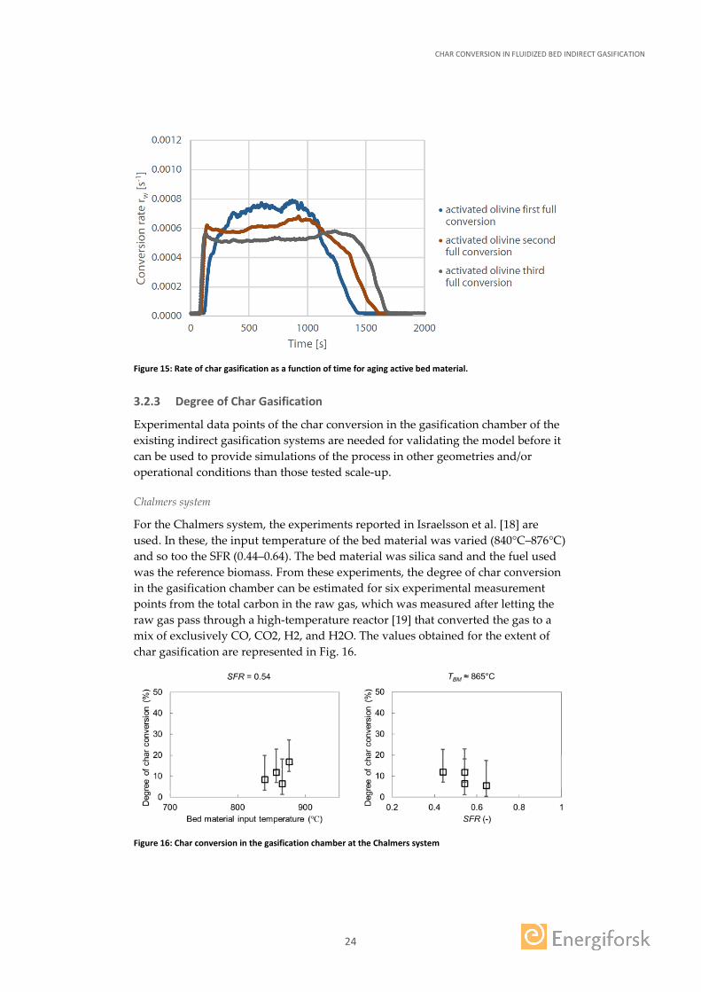
The effect of the aging of the active bed material was also studied and is illustrated in Fig. 15, where the same bed material yields slower gasification rates after each experiment under the same operational conditions.
CHAR CONVERSION IN FLUIDIZED BED INDIRECT GASIFICATION
24
Figure 15: Rate of char gasification as a function of time for aging active bed material.
3.2.3 Degree of Char Gasification
Experimental data points of the char conversion in the gasification chamber of the existing indirect gasification systems are needed for validating the model before it can be used to provide simulations of the process in other geometries and/or operational conditions than those tested scale-up.
Chalmers system
For the Chalmers system, the experiments reported in Israelsson et al. [18] are used. In these, the input temperature of the bed material was varied (840°C–876°C) and so too the SFR (0.44–0.64). The bed material was silica sand and the fuel used was the reference biomass. From these experiments, the degree of char conversion in the gasification chamber can be estimated for six experimental measurement points from the total carbon in the raw gas, which was measured after letting the raw gas pass through a high-temperature reactor [19] that converted the gas to a mix of exclusively CO, CO2, H2, and H2O. The values obtained for the extent of char gasification are represented in Fig. 16.
Figure 16: Char conversion in the gasification chamber at the Chalmers system
CHAR CONVERSION IN FLUIDIZED BED INDIRECT GASIFICATION
25
Note that the uncertainty in the char yield (18–20% [17]), as well as in the amount of carbon in the char (92–100% [20]) yield a certain confidence interval in the values obtained. The amount of recirculated char from the combustor into the gasifier has been neglected.
GoBiGas system
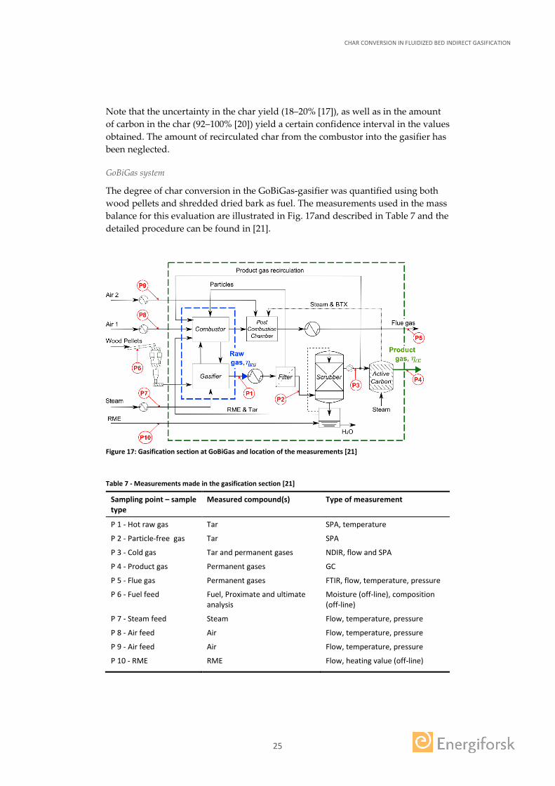
The degree of char conversion in the GoBiGas-gasifier was quantified using both wood pellets and shredded dried bark as fuel. The measurements used in the mass balance for this evaluation are illustrated in Fig. 17and described in Table 7 and the detailed procedure can be found in [21].
Figure 17: Gasification section at GoBiGas and location of the measurements [21]
Table 7 - Measurements made in the gasification section [21]
Sampling point – sample type
Measured compound(s) Type of measurement
P 1 - Hot raw gas Tar SPA, temperature
P 2 - Particle-free gas Tar SPA
P 3 - Cold gas Tar and permanent gases NDIR, flow and SPA
P 4 - Product gas Permanent gases GC
P 5 - Flue gas Permanent gases FTIR, flow, temperature, pressure
P 6 - Fuel feed Fuel, Proximate and ultimate analysis
Moisture (off-line), composition (off-line)
P 7 - Steam feed Steam Flow, temperature, pressure
P 8 - Air feed Air Flow, temperature, pressure
P 9 - Air feed Air Flow, temperature, pressure
P 10 - RME RME Flow, heating value (off-line)
CHAR CONVERSION IN FLUIDIZED BED INDIRECT GASIFICATION
26
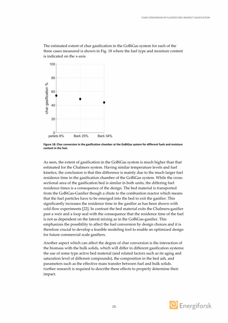
The estimated extent of char gasification in the GoBiGas system for each of the three cases measured is shown in Fig. 18 where the fuel type and moisture content is indicated on the x-axis.
Figure 18: Char conversion in the gasification chamber at the GoBiGas system for different fuels and moisture content in the fuel.
As seen, the extent of gasification in the GoBiGas system is much higher than that estimated for the Chalmers system. Having similar temperature levels and fuel kinetics, the conclusion is that this difference is mainly due to the much larger fuel residence time in the gasification chamber of the GoBiGas system. While the cross-sectional area of the gasification bed is similar in both units, the differing fuel residence times is a consequence of the design. The bed material is transported from the GoBiGas-Gasifier though a chute to the combustion reactor which means that the fuel particles have to be emerged into the bed to exit the gasifier. This significantly increases the residence time in the gasifier as has been shown with cold flow experiments [22]. In contrast the bed material exits the Chalmers-gasifier past a weir and a loop seal with the consequence that the residence time of the fuel is not as dependent on the lateral mixing as in the GoBiGas-gasifier. This emphasizes the possibility to affect the fuel conversion by design choices and it is therefore crucial to develop a feasible modeling tool to enable an optimized design for future commercial scale gasifiers.
Another aspect which can affect the degree of char conversion is the interaction of the biomass with the bulk solids, which will differ in different gasification systems: the use of some type active bed material (and related factors such as its aging and saturation level of different compounds), the composition in the bed ash, and parameters such as the effective mass transfer between fuel and bulk solids. Further research is required to describe these effects to properly determine their impact.

CHAR CONVERSION IN FLUIDIZED BED INDIRECT GASIFICATION
27
4 Results
4.1 MODEL VALIDATION
Figure 19 shows experimental and modelled values for the degree of char conversion in the Chalmers gasifier, as a function of the input temperature of bed material and the SFR. As seen, the modelled results give a fairly satisfactory fit with the experimental measurements. The effect of temperature on the char reactivity seems so be somewhat underestimated by the model, whereas the residence time of the fuel is somewhat overestimated. However, it should be noted that the uncertainties of the experimental data are rather large.
Figure 19: Char conversion in the Chalmers gasifier as a function of: a) the inlet temperature of bed material; and b) the steam-fuel-ratio.
Regarding the GoBiGas system, the pellets case was simulated with the 3-dimensional model. In this simulation, the geometry of the gasification reactor in the indirect gasification system is modified to a reactor with a square cross section (variable with height) instead of the original circular one, while the cross-sectional area is kept at all heights. This is a demand set by the limitation of the implemented 3-dimensional model of not handling circular geometries and thus relativizes the value of a strong quantitative agreement between the measured and simulated values shown in Table 8.
Table 8: Measured and simulated char conversion in the GoBiGas gasifier for the case using pellets as fuel
Experimental Simulated
54% 45%
4.2 CHALMERS AND GOBIGAS SYSTEMS
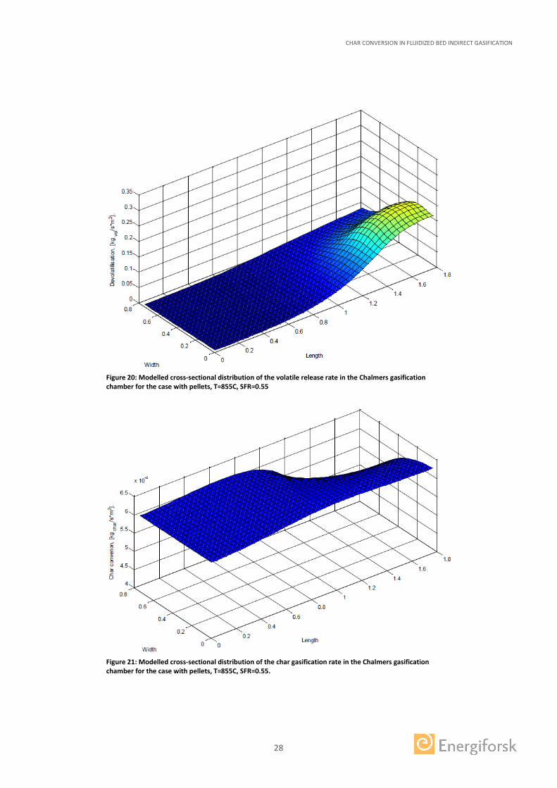
Results from the 3-dimensional simulations showing the cross-sectional distributions of the rates for volatile release and char gasification in the Chalmers gasification chamber are shown in Figs 20 and 21. The case represented uses pellets, T=855C and SFR=0.55. In these representations, the feeding of fuel occurs from the right-bottom corner and that of the solids from the right-top corner. The solid outlet is located at the left-top corner.
CHAR CONVERSION IN FLUIDIZED BED INDIRECT GASIFICATION
28
Figure 20: Modelled cross-sectional distribution of the volatile release rate in the Chalmers gasification chamber for the case with pellets, T=855C, SFR=0.55
Figure 21: Modelled cross-sectional distribution of the char gasification rate in the Chalmers gasification chamber for the case with pellets, T=855C, SFR=0.55.

CHAR CONVERSION IN FLUIDIZED BED INDIRECT GASIFICATION
29
As seen, the model estimates that, for the case studied, all volatiles are released in the gasification chamber, especially close to the fuel feeding location. Regarding the char gasification, the horizontal distribution is relatively homogeneous over the cross section of the gasifier excepting for a significant deep close to the region where the circulating solids are fed, due to the convective drag pulling char particles away from this region.
Concerning the GoBiGas system, the fuel conversion in the gasifier was quantified in terms of the raw gas efficiency (denoted eff RG in Fig. 22), which indicates the fraction of chemically bound energy restored from the dry ash free fuel to the raw and tar containing gas. One can see a clear difference between the bark and the pellets which is related to the char contents of the fuel where the bar yield more than 23-24% of char while the wood pellets yields around 16% as well as due to the slight difference in the degree of char conversion, Fig. 22. Part of the energy containing components in the raw gas are polyaromatic hydrocarbons (PAHs) and other tar compounds which can cause fouling on downstream equipment. These components are therefore removed from the gas, which also gives a loss in efficiency. Further, part of the gas needs to be recirculated to the combustion section to provide enough heat to the process. The remaining gas, i.e. that which can be used for synthesis, is referred to as net cold gas, and the fraction of the fuel energy retained in this gas stream is denoted the cold gas efficiency (eff CG). The difference in the cold gas efficiency is related both to the difference in the raw gas efficiency but even more so the moisture content of the fuel. This is due to the fact that with more water in the fuel more of the gas has to be combusted to maintain the temperature of the process. The efficiency of the conversion to the dry ash free biomass into methane are denoted eff CH4 and are directly correlated to the cold gas efficiency.
Figure 22: Plant efficiency at the GoBiGas system estimated using 84% efficiency for the methanation section of the plant. eff RG - raw gas efficiency, eff CG - cold gas efficiency, eff CH4 - efficiency of methane production.

CHAR CONVERSION IN FLUIDIZED BED INDIRECT GASIFICATION
30
4.3 PROCESS OPTIMIZATION AND SCALE-UP
The effect of operational parameters, such as the solids cross-flow and the temperature of the bed material entering the gasifier, on the degree of char conversion in the gasification chamber of up-scaled systems is investigated by means of model simulations. With this, challenges in the up-scaling of the technology are identified. In these up-scale simulations the solids outlet from the gasification chamber modelled is assumed to be of the same type as in the Chalmers gasifier, i.e. from the dense bed surface. This, since the arrangement of a solids outlet from the bottom of the bed for the significant magnitudes of the solid mass flows involved has not been technically demonstrated yet..
Figure 23.a shows the modelled degree of char conversion in the gasifier as a function of the normalised solids cross-flow for fuel thermal inputs of 1, 10, and 100 MW, for inlet solids temperature of 900ºC and SFR=0.2. As seen, the char conversion curves for any unit scale have a peak form when plotted as a function of the solids crossflow. This is due to that char conversion is a result of the combination of the fuel residence time and the char gasification rate, the latter being governed by temperature, which have opposite trends with the solids crossflow, as shown in Fig. 23.b for the 10 MW case. Furthermore, note that the peak char conversion in Fig. 23.a increases with scale, which is due to the increase in fuel residence time. The char conversion peak also narrows with scale, as for larger unit sizes the fuel residence time is dominated by fuel convection, which makes the fuel residence time more sensitive to an increase in solids circulation than in small units.
Figure 23. a) Degree of char conversion for gasifiers of 1 MW, 10 MW, and 100 MW, as a function of the solids cross-flow normalised with the mass-flow of fuel entering the gasifier; and b) the average temperature within the gasifier versus the fuel residence time for a 10 MW gasifier.
The degree of char conversion in the gasification chamber should be as close as possible to the value yielding thermal balance between char combustion and the internal heat demand of the system. This value lies typically within the range 10–50%. However, as seen in Fig. 23a, such a high degree of char conversion in the gasifier may be difficult to achieve, especially for small-scale units (at the given standard conditions, the 10 MW unit cannot reach char conversion values higher than 15%).
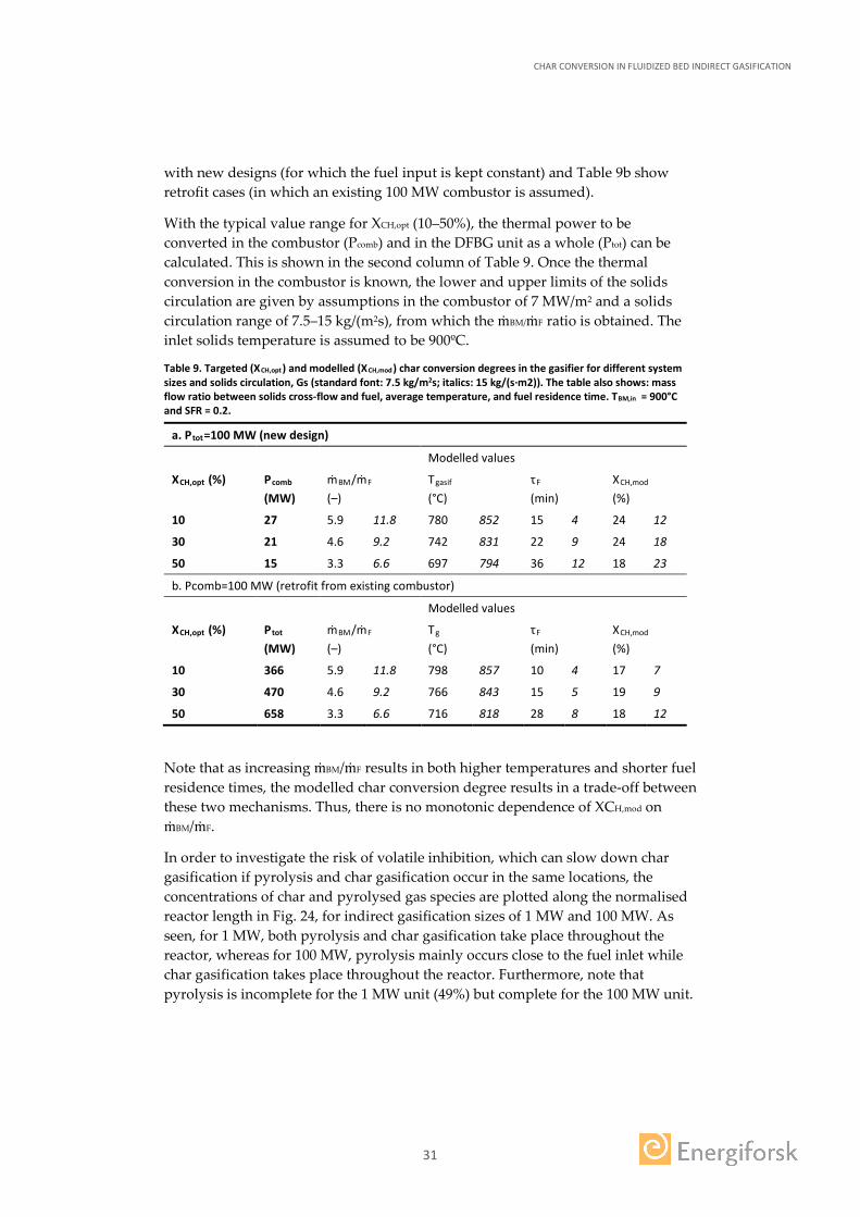
Table 9 shows a comparison between assumed targeted values of the char conversion in the gasifier and the ones obtained by modeling. Table 9a show cases
CHAR CONVERSION IN FLUIDIZED BED INDIRECT GASIFICATION
31
with new designs (for which the fuel input is kept constant) and Table 9b show retrofit cases (in which an existing 100 MW combustor is assumed).
With the typical value range for XCH,opt (10–50%), the thermal power to be converted in the combustor (Pcomb) and in the DFBG unit as a whole (Ptot) can be calculated. This is shown in the second column of Table 9. Once the thermal conversion in the combustor is known, the lower and upper limits of the solids circulation are given by assumptions in the combustor of 7 MW/m2 and a solids circulation range of 7.5–15 kg/(m2s), from which the ṁBM/ṁF ratio is obtained. The inlet solids temperature is assumed to be 900ºC.
Table 9. Targeted (XCH,opt) and modelled (XCH,mod) char conversion degrees in the gasifier for different system sizes and solids circulation, Gs (standard font: 7.5 kg/m2s; italics: 15 kg/(s∙m2)). The table also shows: mass flow ratio between solids cross-flow and fuel, average temperature, and fuel residence time. TBM,in = 900°C and SFR = 0.2.
a. Ptot=100 MW (new design)
Modelled values
XCH,opt (%) Pcomb (MW)
ṁBM/ṁF (–)
Tgasif (°C)
τF (min)
XCH,mod (%)
10 27 5.9 11.8 780 852 15 4 24 12
30 21 4.6 9.2 742 831 22 9 24 18
50 15 3.3 6.6 697 794 36 12 18 23
b. Pcomb=100 MW (retrofit from existing combustor)
Modelled values
XCH,opt (%) Ptot (MW)
ṁBM/ṁF (–)
Tg (°C)
τF (min)
XCH,mod (%)
10 366 5.9 11.8 798 857 10 4 17 7
30 470 4.6 9.2 766 843 15 5 19 9
50 658 3.3 6.6 716 818 28 8 18 12
Note that as increasing ṁBM/ṁF results in both higher temperatures and shorter fuel residence times, the modelled char conversion degree results in a trade-off between these two mechanisms. Thus, there is no monotonic dependence of XCH,mod on ṁBM/ṁF.
In order to investigate the risk of volatile inhibition, which can slow down char gasification if pyrolysis and char gasification occur in the same locations, the concentrations of char and pyrolysed gas species are plotted along the normalised reactor length in Fig. 24, for indirect gasification sizes of 1 MW and 100 MW. As seen, for 1 MW, both pyrolysis and char gasification take place throughout the reactor, whereas for 100 MW, pyrolysis mainly occurs close to the fuel inlet while char gasification takes place throughout the reactor. Furthermore, note that pyrolysis is incomplete for the 1 MW unit (49%) but complete for the 100 MW unit.

CHAR CONVERSION IN FLUIDIZED BED INDIRECT GASIFICATION
32
Figure 24. Concentration of pyrolysed gas species that cause volatile inhibition and char concentration along the gasification chamber, for DFBG units of: a) 1 MW; and b)
For small-scale indirect gasification systems, three challenges have been identified in the gasifier: 1) the fuel residence time is too short to achieve a high enough degree of char conversion even at fairly high temperature; 2) volatile inhibition can be significant; and 3) pyrolysis can be incomplete. Thus, even when a solids cross-flow is applied which maximises char gasification, this may not yield a high enough char conversion.
A suitable solution for increasing the char conversion at small gasifier scales is the use of baffles: Figure 25 shows that the level of char gasification increases from 2% to 22% as a baffle is introduced close to the outlet of a 1 MW gasifier. Furthermore, the placement of the baffle strongly affects the char conversion, which becomes 4% when the baffle is placed close to the inlet, due to low char concentrations after the baffle. Other ways to achieve higher char conversion degrees could involve the use of a catalytic bed material.
Figure 25. Char gasification flux along the length of a 1 MW gasifier (fuel inlet to outlet) with and without the use of baffles. Degree of char conversion is given in the legend.
For large scales, the challenge consists in that while higher char conversion degrees are achieved, they are still limited by the trade-off between fuel residence time and reactor temperature (see Fig. 23b). In line with this, Table 9 shows that adjusting the solids circulation rate, Gs, is not enough to achieve the required degree of char gasification, XCH,opt, if this latter is high (since low solids circulation results in too
CHAR CONVERSION IN FLUIDIZED BED INDIRECT GASIFICATION
33
low gasifier temperatures, while higher circulation yields too short fuel residence times). As for volatile inhibition, it is less of an issue in large-scale gasifiers, as natural separation occurs between pyrolysis and char gasification (see Fig. 24b).
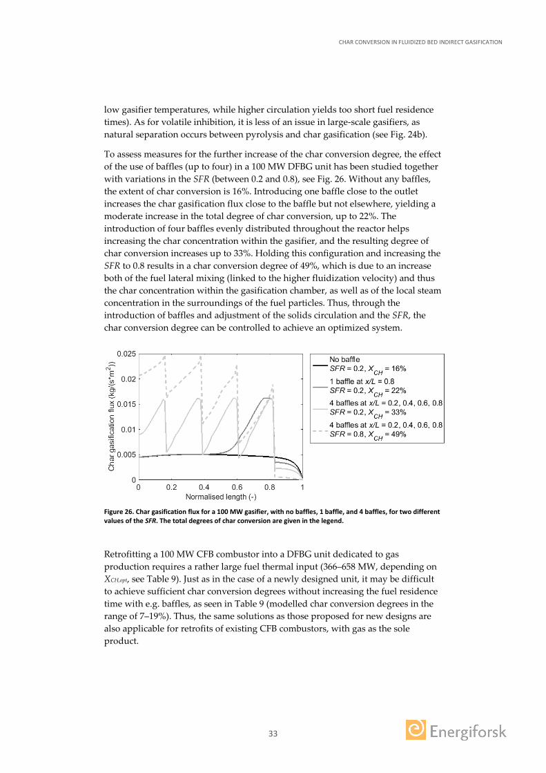
To assess measures for the further increase of the char conversion degree, the effect of the use of baffles (up to four) in a 100 MW DFBG unit has been studied together with variations in the SFR (between 0.2 and 0.8), see Fig. 26. Without any baffles, the extent of char conversion is 16%. Introducing one baffle close to the outlet increases the char gasification flux close to the baffle but not elsewhere, yielding a moderate increase in the total degree of char conversion, up to 22%. The introduction of four baffles evenly distributed throughout the reactor helps increasing the char concentration within the gasifier, and the resulting degree of char conversion increases up to 33%. Holding this configuration and increasing the SFR to 0.8 results in a char conversion degree of 49%, which is due to an increase both of the fuel lateral mixing (linked to the higher fluidization velocity) and thus the char concentration within the gasification chamber, as well as of the local steam concentration in the surroundings of the fuel particles. Thus, through the introduction of baffles and adjustment of the solids circulation and the SFR, the char conversion degree can be controlled to achieve an optimized system.
Figure 26. Char gasification flux for a 100 MW gasifier, with no baffles, 1 baffle, and 4 baffles, for two different values of the SFR. The total degrees of char conversion are given in the legend.
Retrofitting a 100 MW CFB combustor into a DFBG unit dedicated to gas production requires a rather large fuel thermal input (366–658 MW, depending on XCH,opt, see Table 9). Just as in the case of a newly designed unit, it may be difficult to achieve sufficient char conversion degrees without increasing the fuel residence time with e.g. baffles, as seen in Table 9 (modelled char conversion degrees in the range of 7–19%). Thus, the same solutions as those proposed for new designs are also applicable for retrofits of existing CFB combustors, with gas as the sole product.

CHAR CONVERSION IN FLUIDIZED BED INDIRECT GASIFICATION
34
5 Assessment of Aim Achievement
An assessment of the achievement of the project goals is given below:
Impact goal - To bring indirect gasification technology closer to commercialization by improving the generic knowledge of char conversion in indirect gasification, developing models that can determine the char conversion in systems of different scale and can be used in the design of the process.
The project has increased the knowledge on the degree of char conversion in indirect gasification (sections 3.2 and 4.2) and delivered a modeling tool which satisfactorily describes the char conversion and can be used in process design and scale-up (sections 2, 4.1 and 4.3). This represents a valuable tool and knowledge which makes indirect gasification become closer to commercialization.
Project goal P1) To develop general knowledge of the factors and mechanisms by which char conversion is governed in indirect gasification plants. Such knowledge is of great importance for the design, control and scale-up of the process.
The factors influencing char conversion in indirect gasification and studied within this project have been mapped in Fig. 27.
Figure 27: Factors affecting the degree of char conversion in the gasification chamber of an indirect gasification system.
The mechanisms by which each factor governs char gasification have been studied and knowledge gaps have been filled (sections 3.2.1 and 3.2.2).
Project goal P2) To determine the kinetical data for fuels that are relevant to the GoBiGas project. For this purpose, a laboratory reactor with access to raw gas from the Chalmers process is to be built which can be used to study individual mechanisms in char conversion, such as kinetics and interactions with the bed material.
Kinetical data for the relevant fuel has been determined (section 3.2.2) in a laboratory reactor built for this purpose with access to raw gas from the Chalmers
CHAR CONVERSION IN FLUIDIZED BED INDIRECT GASIFICATION
35
process (section 3.1.2) and has been used to study how char kinetics are influenced by surrounding conditions and by bed material (section 3.2.2).
Project goal P3) To produce validation data for the char conversion in the Chalmers and GoBiGas systems. Data provides knowledge of how mixing phenomena affect char conversion and provides a basis for generalizing the understanding of char conversion.
Validation data for the char conversion in the Chalmers and GoBiGas systems has been produced and generated valuable knowledge on how the different system designs influence char conversion (section 3.2.2).
Project goal P4) To develop models that describe char conversion in the various plants, taking into account the different mechanisms for mixing and kinetics. These models, based on tests at laboratory and large scales, gather knowledge about char conversion and are general in the sense that can be used as a tool for developing the process.
A holistic model has been developed (see formulation in section 2) which includes transport and generation of the gas, fuel and enthalpy. The model is validated against data from pilot and demonstration scales (section 4.1) and is used to study process up-scale (section 4.3).

CHAR CONVERSION IN FLUIDIZED BED INDIRECT GASIFICATION
36
6 Publications
The tasks carried out within the project have led to the following publications.
Journal publications
Lundberg, L., Johansson, R., Pallarès, D., Thunman, H. 2017. “A conversion-class model for describing fuel conversion in large-scale fluidized bed units”. Fuel, 197, pp.42–50.
Lundberg, L., Pallarès, D., Thunman, H. 2017. “Upscaling Effects on Char Conversion in Dual Fluidized Bed Gasification”, submitted for publication.
Lundberg, L., Tchoffor, P.A., Pallarès, D., Thunman, H., Davidsson, K. 2017. “Effect of the Bed Material on Steam Gasification of Char”, submitted for publication.
Lundberg, L., Soria-Verdugo, A., Pallarès, D., Johansson, R., Thunman, H. 2016. “The role of fuel mixing on char conversion in a fluidized bed”. Powder Technology, article in press
Lundberg, L., Tchoffor, P.A., Pallarès, D., Johansson, R., Thunman, H., Davidsson, K. 2016. “Influence of Surrounding Conditions and Fuel Size on the Gasification Rate of Biomass Char in a Fluidized Bed”. Fuel Processing Technology, 144, pp.323-333.
Sette, E., Berdugo Vilches, T., Pallarès, D., Johnsson, F. 2016. “Measuring fuel mixing under industrial fluidized-bed conditions - a camera-probe based fuel tracking system”. Applied Energy, 163, pp. 304-312.
Conference articles
Lundberg, L., Soria-Verdugo, A., Pallarès, D., Johansson, R., Thunman, H. 2016. ”The role of fuel mixing on char conversion in a fluidized bed”. Proc. of the 15th Int. Conf. on Fluidization (Montebello, Canada).
Sette, E., Pallarès, D., Johnsson, F. 2015. “Camera-probe fuel tracking under industrial fluidized-bed conditions”. Proc. of the 22nd Int. Conf. on Fluidized Bed Combustion (Turku, Finland).
Lundberg, L., Atongka-Tchoffor, P., Johansson, R., Pallarès, D. 2015. ”Determination of kinetic parameters for the gasification of biomass char using a bubbling fluidized bed reactor”. Proc. of the 22nd Int. Conf. on Fluidized Bed Combustion (Turku, Finland).

CHAR CONVERSION IN FLUIDIZED BED INDIRECT GASIFICATION
37
7 References
[1] Swedish Goverment, 2008. ''En sammanhållen klimat- och energipolitik''. 2008/09:162.
[2] Larsson A, Seemann M, Neves D, Thunman H. 2013. “Evaluation of performance of industrial-scale dual fluidized bed gasifiers using the Chalmers 2-4-MWth gasifier”. Energy Fuels 27:6665-80.
[3] Xu G, Murakami T, Suda T, Matsuzawa Y, Tani H. 2006. “The superior technical choice for dual fluidized bed gasification”. Industrial Engineering and Chemistry Research 45:2281-6.
[4] Pallarès D. Fluidized bed combustion -modelling and mixing [Doctoral Thesis]. Göteborg: Chalmers University of Technology; 2008
[5] Radmanesh R, Cnaouki J, Guy C. 2006. “Biomass gasification in a bubbling fluidized bed reactor: Experiments and modeling”. AIChE Journal 52:4258-72.
[6] Petersen I, Werther J. 2005. ”Three-dimensional modeling of a circulating fluidized bed gasifier for sewage sludge”. Chemical Engineering Science 60:4469-84.
[7] Kunii D, Levenspiel O. 1991. ”Fluidization Engineering”, Butterworth-Heine- mann Eds, Boston, M.A.
[8] Lundberg L, Johansson R, Pallarès D, Thunman H. 2017. “A conversion-class model for describing fuel conversion in large-scale fluidized bed units”. Fuel 197:42–50.
[9] Lundberg L, Pallarès D, Thunman H. 2017. “Upscaling Effects on Char Conversion in Dual Fluidized Bed Gasification”, to be submitted for publication.
[10] Sette E, Pallarès D, Johnsson F. 2015. “Camera-probe fuel tracking under industrial fluidized-bed conditions”. Proc. of the 22nd Int. Conf. on Fluidized Bed Combustion (Turku, Finland).
[11] Sette E, Berdugo Vilches T, Pallarès D, Johnsson F. 2016. “Measuring fuel mixing under industrial fluidized-bed conditions - a camera-probe based fuel tracking system”. Applied Energy 163:304-312.
[12] Lundberg L, Atongka-Tchoffor P, Johansson R, Pallarès D. 2015. ”Determination of kinetic parameters for the gasification of biomass char using a bubbling fluidized bed reactor”. Proc. of the 22nd Int. Conf. on Fluidized Bed Combustion (Turku, Finland).
[13] Lu G Q, Do D D. 1994. “Comparison of structural models for high-ash char gasification”. Carbon 32:247-263.
[14] Ishida M, Wen C Y. 1971. ”Comparison of zone-reaction model and unreacted-core shrinking model in solid-gas reactions – I Isothermal analysis”. Chemical Engineering Science 26:1031-1041

CHAR CONVERSION IN FLUIDIZED BED INDIRECT GASIFICATION
38
[15] Bhatia SK, Perlmutter DD. 1980. ”A random pore model for fluid-solid reactions: I. Isothermal, kinetic control”. American Institute of Chemical Engineers Journal 26:379–86
[16] Nilsson S., Gómez-Barea A., Fuentos Cano D. 2012. ”Gasification reactivity of char from dried sewage sludge in a fluidized bed”. Fuel 92:346-353.
[17] Lundberg L, Tchoffor PA, Pallarès D, Johansson R, Thunman H, Davidsson K. 2016. “Influence of Surrounding Conditions and Fuel Size on the Gasification Rate of Biomass Char in a Fluidized Bed”. Fuel Processing Technology 144:323-333.
[18] Israelsson M, Berdugo Vilches T, Thunman H. 2015. ”Conversion of Condensable Hydrocarbons in a Dual Fluidized Bed Biomass Gasifier”. Energy Fuels 29:6465-75.
[19] Israelsson M, Larsson A, Thunman H. 2014. ”Online measurement of elemental yields, oxygen transport, condensable compounds, and heating values in gasification systems”. Energy Fuels 28:5892-901.
[20] Neves D, Thunman H, Matos A, Tarelho L, Gómez-Barea A. 2011. ”Characterization and prediction of biomass pyrolysis products”. Progress in Energy and Combustion Science 37:611–630.
[21] Alamia A, Gardarsdòttir SÒ, Larsson A, Norrman F, Thunman H. 2017 “Comparison of decentralized and standalone thermochemical biorefineries at large scale”. Submitted to Energy Technology.
[22] Zhao K, Thunman H, Pallarès D, Ström H. 2017. “Control of the solids retention time by multi-staging a fluidized bed reactor”. Submitted to Fuel Processing Technology.


CHAR CONVERSION IN FLUIDIZED BED INDIRECT GASIFICATIONThis project brings new knowledge to the phenomenon of char conversion in indirect gasification, a technically proven process which provides highly efficient conversion of biomass and is thus considered a key factor in the phase out of fossil fuels.
The combination of experimental and modeling work has yield new key know-ledge on char conversion in indirect gasification systems, such as the possibility to influence char reactivity through fuel segregation (i.e. through fuel size), the strong effect on the gasification rate of having an active bed material instead of sand and the limited influence of the solids circulation on the fuel residence time when compared to that of the fluidization velocity. Scale-up simulation with the validated model developed show that the influence on char conversion of the solids circulation rate increases with scale, and that the residence time of char in the gasification chamber becomes a critical parameter to maximize at larger scales.
Energiforsk is the Swedish Energy Research Centre – an industrially owned body dedicated to meeting the common energy challenges faced by industries, authorities and society. Our vision is to be hub of Swedish energy research and our mission is to make the world of energy smarter!