chapter3 datalink layer
DESCRIPTION
networkTRANSCRIPT

The Data Link Layer
Chapter 3

Functions of the Data Link Layer
• Provide service interface to the network layer
• Dealing with transmission errors
• Regulating data flow• Slow receivers not swamped by fast senders

Functions of the Data Link Layer (2)
Relationship between packets and frames.

Data Link Layer Design Issues
• Services Provided to the Network Layer
• Framing
• Error Control
• Flow Control

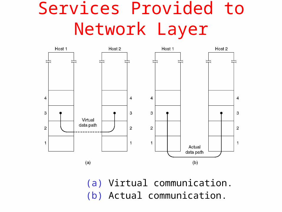
Services Provided to the Network Layer
a) Principal Service Function of the data link layer is to transfer the data from the network layer on the source machine to the network layer on the destination machine.
Services Provided to Network Layer
(a) Virtual communication.(b) Actual communication.

Possible Services Offered
Data link layer provides three types of services:• Unacknowledged connectionless service.• Acknowledged connectionless service.• Acknowledged connection-oriented service.
Unacknowledged Connectionless Service
a) No logical connection is established and if a frame is lost due to noise on the line, no attempt is made to detect the loss or recover from it in the data link layer.
b) Example: Ethernet, Voice over IP, etc. in all the communication channel were real time operation is more important that quality of transmission.
Acknowledged Connection less Service
• No logical connection used but each frame sent is individually acknowledged.
• This service is useful over unreliable channels such as wireless systems.
• Frames usually have a strict maximum length, imposed by the hardware and network layer does not.
Acknowledged Connection Oriented Service
a) Source and Destination establish a connection first.
b) Each frame sent is numbered
– Data link layer guarantees that each frame sent is indeed received.
– It guarantees that each frame is received only once and that all frames are received in the correct order.
c) Examples:
– Satellite channel communication,
– Long-distance telephone communication, etc.

Acknowledged Connection Oriented Service
Three distinct phases:
1. Connection is established by having both side initialize variables and counters needed to keep track of which frames have been received and which ones have not.
2. One or more frames are transmitted.
3. Finally, the connection is released – freeing up the variables, buffers, and other resources used to maintain the connection.

Services Provided to Network Layer (2)
Placement of the data link protocol.

FRAMINGFRAMING
The data link layer needs to The data link layer needs to pack bits into framespack bits into frames, so that each , so that each frame is distinguishable from another.frame is distinguishable from another.
Ex:Ex: Our Our postal systempostal system practices a type of practices a type of framingframing. The simple . The simple act of inserting a letter into an envelope separates one piece of act of inserting a letter into an envelope separates one piece of information from another; the envelope serves as the delimiter. In information from another; the envelope serves as the delimiter. In addition each envelope defines the sender and receiver addresses addition each envelope defines the sender and receiver addresses since the postal system is a many-to-many carrier facility.since the postal system is a many-to-many carrier facility.
Fixed-Size FramingVariable-Size Framing : Define the end of the frame and the beginning of the next.Two approaches 1.Character oriented protocols2.Bit –oriented protocols

Four Methods:
a) Character count
b) Flag bytes with byte stuffing
c) Starting and ending flags, with bit stuffing.
d) Physical layer coding violations

A frame in a character-oriented protocol
Source and destination information
Error detection and correction, redundant
bits.
•To separate one frame from the next, an 8-bit (1-byte) flag is added at the beginning and the end of a frame.
• The Flag, composed of protocol-dependent special characters,signlas the start/end of a frame

Byte stuffing and unstuffing

Byte stuffing is the process of adding 1 extra byte whenever there is a flag or escape character in the text.

A frame in a bit-oriented protocol

Bit stuffing is the process of adding one extra 0 whenever five consecutive 1s follow a 0 in the data, so
that the receiver does not mistakethe pattern 0111110 for a flag.

Bit stuffing and unstuffing

Framing
A character stream. (a) Without errors. (b) With one error.
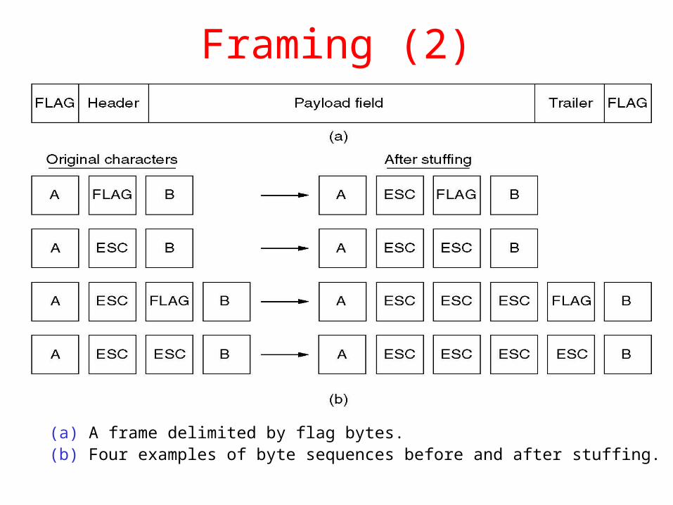
Framing (2)
(a) A frame delimited by flag bytes.(b) Four examples of byte sequences before and after stuffing.

Framing (3)
Bit stuffing
(a) The original data.
(b) The data as they appear on the line.
(c) The data as they are stored in receiver’s memory after destuffing.

Error Control:
1. How to make sure all frames are eventually delivered to the network layer at the destination and in the upper layer.
2. Receiver has to send positive or negative acknowledgements.
3. If the sender receives a positive acknowledgements about a frame, it knows the frame has arrived safely.
4. Negative acknowledgements means that something has gone wrong, and the frame must be transmitted again.
5. If a frame vanishes completely, then the receiver will not react at all, since it has no reason to react & sender transmits a frame and then waits for an ACK.
6. To overcome this we use TIMER.
7. If timer expires, then the sender sends the frame again.
8. If sender sends same frames multiple times then also problem, so we assign sequence numbers to outgoing frames.

4.Flow Control :
1. Another design occurs in the data link layer (and higher layers as well) is what to do with a sender that systematically wants to transmit frames faster than the receiver can accept them.
2. This situation can usually occur when the sender is running on a fast (or light loaded) computer and the receiver is running on a slow (or heavily loaded) machine.
3. The sender keeps pumping the frames out at a high rate until the receiver is completely swamped.
4. Even if the transmission is error free, at certain point the receiver will simply be unable to handle the frames as they arrive and will start to lose some.

Two approaches are commonly used to avoid this situation:
a) Feedback –based flow control:
The receiver sends back information to the sender giving it permission to send more data or at least telling the sender how the receiver is doing.
b) Rate-based flow control:
The protocol has built-in mechanism that limits the rate at which senders may transmit data, without using feedback from the receiver.

Error Detection and Correction
• Error-Correcting Codes
• Error-Detecting Codes

Error-Correcting Codes
Use of a Hamming code to correct burst errors.

Cyclic Redundancy CheckCRC

Cyclic Redundancy CheckCyclic Redundancy Checka) Given a k-bit frame or message, the transmitter
generates an n-bit sequence, known as a frame check sequence (FCS), so that the resulting frame, consisting of (k+n) bits, is exactly divisible by some predetermined number.
b) The receiver then divides the incoming frame by the same number and, if there is no remainder, assumes that there was no error.

Polynomial

Polynomial and Divisor
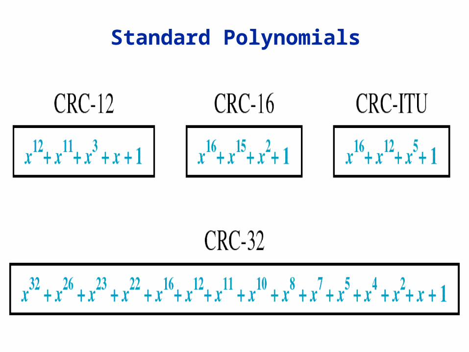
Standard Polynomials

Error-Detecting Codes
Calculation of the polynomial code checksum.

Elementary Data Link Protocols :
1.These protocols deals with communication errors, but not the problems caused by computers crashing and rebooting.
2.When the data link layer accepts a packet, it encapsulates(captures) the packet in a frame by adding a data link header and trailer to it.
3.Frame consists of an embedded packet, some control information (in the header) and a checksum(in the trailer).
4.There exist suitable library procedures to-physical-layer to send a frame and from-physical-layer to receive a frame.
5.When a frame arrives at the receiver ,the hardware computes the checksum. If the checksum is incorrect, the data link layer is so informed (event= cksum_err).
6.If the inbound frame arrived undamaged, the data link layer is also informed(event= frame_arrival) so that it can acquire the frame for inspection using from_physical_layer.

7.The receiving data link layer has acquired an undamaged frame, it checks the control information in the header, and if everything is all right ,passes the packet portion to the network layer.
7. Frame consists of 4 fields: Kind,seq,ack & info
control info data
these control fields collectively called Frame Header
8. To-n/w-layer and from-n/w-layer deal with the interface between layers 2&3.
9. Where as ,from-physical-layer and to-physical-layer deal with the interface between layers 1&2
10.Start –timer,Stop-timer,turn the timer on&off.

Protocol Definitions
Some definitions needed in the protocols to follow. These are located in the file protocol.h.

Protocol Definitions(ctd.)
Some definitions needed in the
protocols to follow. These are located in the file protocol.h.

Elementary Data Link Protocols
• An Unrestricted Simplex Protocol :
1. Data are transmitted in one direction only .both the transmitting and receiving layers are always ready.
2. Processing time can be ignored. Infinite buffer space is available and communication channel never loses or damages.
3. The sender runs in the data link layer of the source machine.
4. The receiver runs in the data link layer of the destination machine.
5. No sequence numbers or acknowledgement's are used here.


• A simple stop-and-wait Protocol:
1. Sender inserts delay into Protocol1.
2. Receiver provides feedback / ack /dummy frames to sender
3. Protocols in which the sender sends one frame and then waits for an acknowledgement before processing are called Stop-and-Wait.
4. Bi –directional channel is needed.


• A simplex protocol for a noisy channel:
1. Adding a timer to protocol2.
2. If acknowledgement gets lost then duplicate frame arrives at network layer.
3. The sender puts a sequence number in the header of each frame.
4. A 1-bit sequence number(0 or 1) is therefore sufficient.
5. At each instant of time ,the receiver expects a particular sequence number next.
6. Protocols in which the sender waits for positive acknowledgement before advancing to the next data item are often called PAR(Positive acknowledgement with retransmission) or ARQ(Automatic Repeat Request).

A Simplex Protocol for a Noisy Channel

A Simplex Protocol for a Noisy Channel (ctd.)
A positive acknowledgement with retransmission protocol.

a) Sliding Window Protocols: At any instant of time, the sender maintains a set of sequence numbers corresponding to frames it is permitted to send. These frames are said to fall within the sending window. Similarly, the receiver also maintain a receiving window corresponding to the set of frames it is permitted to accept.

Sliding Windowsa) Each outbound frame contain a sequence number ranging from 0 to 2n-1
b) Sending window– Maintained by the sender– A set of sequence numbers corresponding to frames the sender is permitted to send
c) Receiving window– Maintained by the receiver– Corresponds the set of frames the receiver is permitted to accept

Maintain Sliding Windows
a) Sending window
– When a frame is sent, the upper edge of the window is advanced by one
– When an acknowledgement is received, the lower edge of the window is advanced by one
b) Receiving window
– Any received frame the sequence number outside the window is discarded
– When a frame whose sequence number is equal to lower edge of the window is received, the window is rotated by one
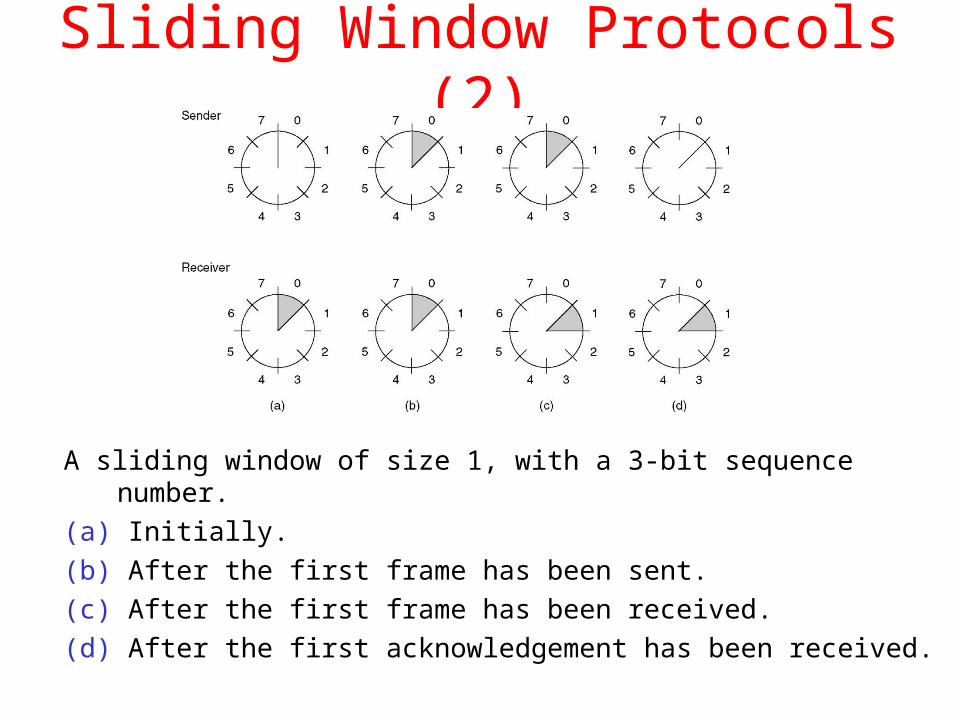
Sliding Window Protocols (2)
A sliding window of size 1, with a 3-bit sequence number.
(a) Initially.
(b) After the first frame has been sent.
(c) After the first frame has been received.
(d) After the first acknowledgement has been received.

Sliding Window Protocols
a) One bit sliding window protocol ( Stop-and-Wait)
b) Go-back-N Protocol
c) Selective Repeat Protocol

One Bit Sliding Window Protocol
a) Stop –and-Wait
– A protocol in which the sender sends one frame and then waits for an acknowledgement before proceeding.
b) a sliding window protocol with maximum window size = 1
– Sequence number {0, 1} is sufficient
c) Frame header fields
– Seq : the sequence number of this frame
– Ack : the number of the last frame is received

A One-Bit Sliding Window Protocol (2)
Two scenarios for protocol 4. (a) Normal case. (b) Abnormal case. The notation is (seq, ack, packet number). An asterisk indicates where a network layer accepts a packet.

Efficiency of Stop-and-Wait
50 kbps data rate500 msec round-trip delay
1000 bits per frame
time (msec)t=0 start sending
t=20 completely sentt=250 frame arrival
t=270 completely receivedt=270 acknowledge without delayt=520 acknowledgement arrival
26000 bits could be transmitted in 520 msec.Efficiency: 1000/26000=20/520 < 4% used
Stop-and-Wait

Efficiency of Stop-and-Wait

Pipelining
50 kbps data rate500 msec round-trip delay
1000 bits per frame
time (msec)t=0 start sending the first frame
t=20 the first completely sentt=250 frame arrival
t=270 the first completely receivedt=270 acknowledge without delayt=520 acknowledgement arrival
To pipeline frames without waiting for acknowledgements.

pipelining

piggybacking
Temporarily delaying outgoing acknowledgements so that they can be hooked onto the next outgoing data
frame is Piggybacking

Line of Utilization for Stop-and-Wait
a) Capacity : b bits/sec, frame size : l bits, round-trip delay : R seconds
– Transmission time : l/b
– Total duration : R + l/b
– Utilization : (l/b) / (R + l/b) = l / (l+bR)

Go-back-N
a) Sender’s window size is n (n >1)
– At most n outstanding frames can be sent
b) After receiving a damaged frame
– Receiver discards all subsequent frames
– Sender retransmits the damaged frame and all its successors after the times out

Go-back-N : An Example

Selective Repeat
a) Receiver’s window size is n ( n >1 )
– At most n frames can be buffered
b) Receiver stores all the correct frames following the bad one
c) The sender retransmits only the bad frame not all its successors

Selective Repeat : An Example

Retransmission with Sliding Window Protocols
a) ARQ (Automatic Repeat reQuest): When an error is detected, the receiver requests that the frame be retransmitted.
– Stop-and-wait ARQ
– Go-back-N continuous ARQ
– Selective-repeat continuous ARQ
b) All of them belong to the sliding window protocols.
c) Both Go-back-N and Selective-repeat ARQs uses the pipelining technique.

Sliding Window Protocol Using Go Back N
Continued

Sliding Window Protocol Using Go Back N

Sliding Window Protocol Using Go Back N (2)
Simulation of multiple timers in software.

A Sliding Window Protocol Using Selective Repeat
Continued

Continued
A Sliding Window Protocol Using Selective Repeat (2)

A Sliding Window Protocol Using Selective Repeat (3)
Continued

A Sliding Window Protocol Using Selective Repeat (4)

A Sliding Window Protocol Using Selective Repeat (5)
(a) Initial situation with a window size seven.
(b) After seven frames sent and received, but not acknowledged.
(c) Initial situation with a window size of four.
(d) After four frames sent and received, but not acknowledged.

Example Data Link Protocols
• HDLC – High-Level Data Link Control
• The Data Link Layer in the Internet
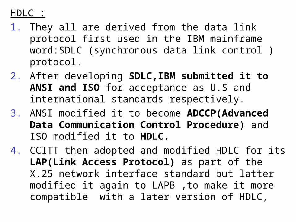
HDLC :
1. They all are derived from the data link protocol first used in the IBM mainframe word:SDLC (synchronous data link control ) protocol.
2. After developing SDLC,IBM submitted it to ANSI and ISO for acceptance as U.S and international standards respectively.
3. ANSI modified it to become ADCCP(Advanced Data Communication Control Procedure) and ISO modified it to HDLC.
4. CCITT then adopted and modified HDLC for its LAP(Link Access Protocol) as part of the X.25 network interface standard but latter modified it again to LAPB ,to make it more compatible with a later version of HDLC,

Example Data Link Protocolsa) HDLC
– bit oriented
– bit stuffing
b) SLIP
c) PPP
– character oriented
– character stuffing
– multiprotocol framing

HDLC Frame Format
a) A frame is delimited with the flag sequence 01111110. On idle point-to-point lines, flag sequences are transmitted continuously.
b) Address– to identify one of multiple terminals for point-
to-multipoint lines– to distinguish commands from responses for
point-to-point lines

76
PtP: examplesa) HDLC: High Level Data Link Control
– Frame structure:
• Address– for multi-point line
– distinguish responses from redirected frames
• Control field
Information frame
Supervisory frames
Unnumbered frames

77
PtP: examplesa) HDLC
– Kind of frames:
• Information frame
• Supervisory frames:
– Reject = nack
– Receive ready = ack
– Receive not ready = ack + stop sending
– Selective reject = resend 1 frame
• Unnumbered frames
– Initialisation
– Polling
– Status reporting
– ….

PtP: examplesa) Data Link layer in the Internet
– Context:
• Dial-up
• Leased lines between routers

PtP: examplesa) PPP – Point-to-Point Protocol
– PPP provides
• Framing + error detection• Link control protocol (LCP) for bringing up lines, test lines,
negotiate options, bringing down lines
• Network control Protocol (NCP) to negotiate options independent of the network protocol used
– Scenario
• PC calls router of provider via modem
• Router’s modem answers phone physical connection
• Series of LCP packets to select PPP parameters
• Series of NCP packets to e.g. get IP address
• PC = Internet host!

The Data Link Layer in the Internet
A home personal computer acting as an internet host.
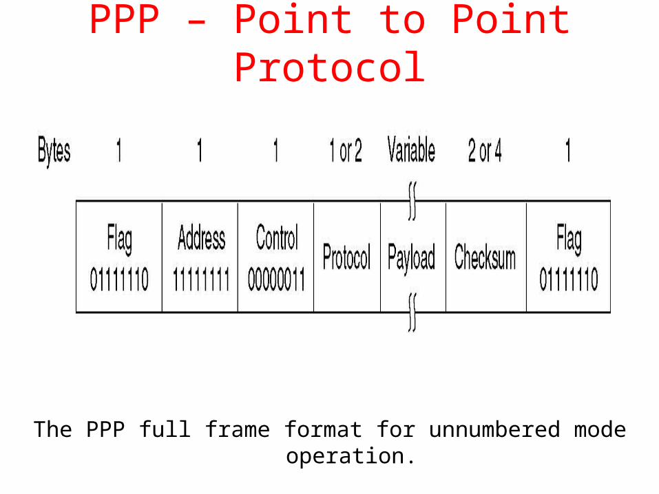
PPP – Point to Point Protocol
The PPP full frame format for unnumbered mode operation.

PPP – Point to Point Protocol (2)
A simplified phase diagram for bring a line up and down.

PPP – Point to Point Protocol (3)
The LCP frame types.