chapter one electric charges and fields · 2019-01-30 · electric charges and fields 3 1.4 five...
TRANSCRIPT

q2
q1
q3
x
y
O
MCQ I
1.1 In Fig.1.1, two positive charges q2 and q
3 fixed along the y axis,
exert a net electric force in the + x direction on a charge q1 fixed
along the x axis. If a positive charge Q is added at (x, 0),the force on q
1
Chapter One
ELECTRIC CHARGES
AND FIELDS
q2
q1
q3
x
y
( 0)x,
Q
O
Fig. 1.1
(a) (b)
21/04/2018

Exemplar Problems–Physics
2
(a) Fig (i) (c) Fig (iii)
(b) Fig (ii) (d) Fig (iv)
1.3 The Electric flux through the surface
(a) in Fig.1.3 (iv) is the largest.
(b) in Fig. 1.3 (iii) is the least.
(c) in Fig. 1.3 (ii) is same as Fig. 1.3 (iii) but is smaller than Fig. 1.3 (iv)
(d) is the same for all the figures.
(a) shall increase along the positive x-axis.
(b) shall decrease along the positive x-axis.
(c) shall point along the negative x-axis.
(d) shall increase but the direction changes because of theintersection of Q with q
2 and q
3.
1.2 A point positive charge is brought near an isolated conductingsphere (Fig. 1.2). The electric field is best given by
+q +q
+q
(i) (ii)
(iv)
(ii) (iii) (iv)(i)
+q
S
+q
S
+q
SS
+q
Fig. 1.3
Fig. 1.2
+q
(iii)
21/04/2018

Electric Charges and Fields
3
1.4 Five charges q1, q
2, q
3, q
4, and q
5 are fixed at their positions as shown
in Fig. 1.4. S is a Gaussian surface. The Gauss’s law is given by
qd
0S
.ε
= E sWhich of the following statements is correct?
(a) E on the LHS of the above equation will have a contributionfrom q
1, q
5 and q
3 while q on the RHS will have a contribution
from q2 and q
4 only.
(b) E on the LHS of the above equation will have a contribution
from all charges while q on the RHS will have a contributionfrom q
2 and q
4 only.
(c) E on the LHS of the above equation will have a contributionfrom all charges while q on the RHS will have a contributionfrom q
1, q
3 and q
5 only.
(d) Both E on the LHS and q on the RHS will have contributionsfrom q
2 and q
4 only.
1.5 Figure 1.5 shows electric field lines in which an electric dipole p isplaced as shown. Which of the following statements is correct?
(a) The dipole will not experience any force.
(b) The dipole will experience a force towards right.
(c) The dipole will experience a force towards left.
(d) The dipole will experience a force upwards.
1.6 A point charge +q, is placed at a distance d from an
isolated conducting plane. The field at a point P on theother side of the plane is
(a) directed perpendicular to the plane and away from
the plane.
(b) directed perpendicular to the plane but towards the plane.
(c) directed radially away from the point charge.
(d) directed radially towards the point charge.
1.7 A hemisphere is uniformly charged positively. The electric field at a
point on a diameter away from the centre is directed
(a) perpendicular to the diameter
(b) parallel to the diameter
(c) at an angle tilted towards the diameter
(d) at an angle tilted away from the diameter.
q1
q5
q4
q2
q3
S
– q + qp
Fig. 1.4
Fig. 1.5
Gaussian Surface
21/04/2018
Exemplar Problems–Physics
4
R/2
Q R
–2Q
R
5Q
Gaussian surface
MCQ II
1.8 If s
.d 0= E S over a surface, then
(a) the electric field inside the surface and on it is zero.
(b) the electric field inside the surface is necessarily uniform.
(c) the number of flux lines entering the surface must be equal tothe number of flux lines leaving it.
(d) all charges must necessarily be outside the surface.
1.9 The Electric field at a point is
(a) always continuous.
(b) continuous if there is no charge at that point.
(c) discontinuous only if there is a negative charge at that point.
(d) discontinuous if there is a charge at that point..
1.10 If there were only one type of charge in the universe, then
(a)s
.d 0≠ E S on any surface.
(b)s
.d 0= E S if the charge is outside the surface.
(c)s
.d E S could not be defined.
(d)s
0
.dq
ε= E S if charges of magnitude q were inside the surface.
1.11 Consider a region inside which there are various types of charges
but the total charge is zero. At points outside the region
(a) the electric field is necessarily zero.
(b) the electric field is due to the dipole moment of the chargedistribution only.
(c) the dominant electric field is 3
1
r∝ , for large r, where r is the
distance from a origin in this region.
(d) the work done to move a charged particle along a closed path,
away from the region, will be zero.
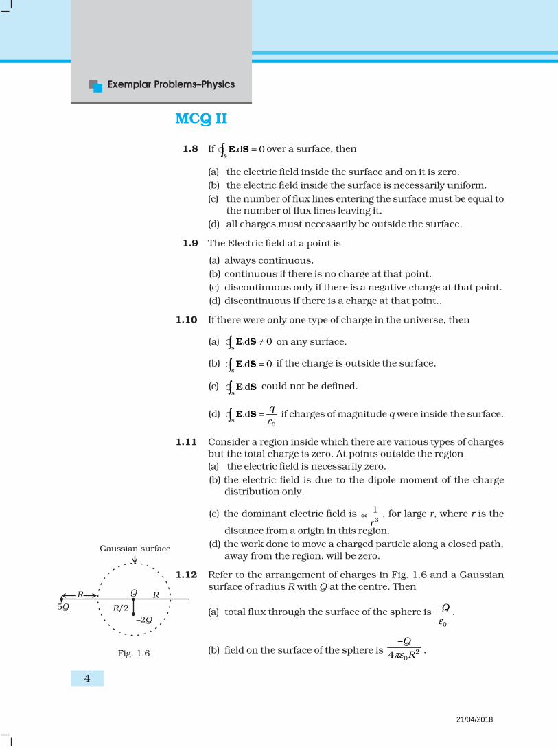
1.12 Refer to the arrangement of charges in Fig. 1.6 and a Gaussian
surface of radius R with Q at the centre. Then
(a) total flux through the surface of the sphere is 0
–Q
ε.
(b) field on the surface of the sphere is 20
–
4
Q
Rπε .Fig. 1.6
21/04/2018

Electric Charges and Fields
5
(c) flux through the surface of sphere due to 5Q is zero.
(d) field on the surface of sphere due to –2Q is same everywhere.
1.13 A positive charge Q is uniformly distributed along a circular
ring of radius R. A small test charge q is placed at the centre ofthe ring (Fig. 1.7). Then
(a) If q > 0 and is displaced away from the centre in the plane
of the ring, it will be pushed back towards the centre.
(b) If q < 0 and is displaced away from the centre in the plane
of the ring, it will never return to the centre and willcontinue moving till it hits the ring.
(c) If q < 0, it will perform SHM for small displacement along
the axis.
(d) q at the centre of the ring is in an unstable equilibrium
within the plane of the ring for q > 0.
VSA
1.14 An arbitrary surface encloses a dipole. What is the electric flux
through this surface?
1.15 A metallic spherical shell has an inner radius R1 and outer radius
R2. A charge Q is placed at the centre of the spherical cavity. What
will be surface charge density on (i) the inner surface, and (ii) theouter surface?
1.16 The dimensions of an atom are of the order of an Angstrom. Thus
there must be large electric fields between the protons and electrons.Why, then is the electrostatic field inside a conductor zero?
1.17 If the total charge enclosed by a surface is zero, does it imply that
the elecric field everywhere on the surface is zero? Conversely, ifthe electric field everywhere on a surface is zero, does it imply thatnet charge inside is zero.
1.18 Sketch the electric field lines for a uniformly charged hollowcylinder shown in Fig 1.8.
Rz
q
++ Q
Fig. 1.7
++
++
++
++
++
++
++
++
++++
++++
Fig. 1.8
21/04/2018

Exemplar Problems–Physics
6
1.19 What will be the total flux through the faces of the cube (Fig. 1.9)with side of length a if a charge q is placed at
(a) A: a corner of the cube.
(b) B: mid-point of an edge of the cube.
(c) C: centre of a face of the cube.
(d) D: mid-point of B and C.
S.A
1.20 A paisa coin is made up of Al-Mg alloy and weighs 0.75g. It has asquare shape and its diagonal measures 17 mm. It is electricallyneutral and contains equal amounts of positive and negative
charges.
Treating the paisa coins made up of only Al, find the magnitude ofequal number of positive and negative charges. What conclusion
do you draw from this magnitude?
1.21 Consider a coin of Example 1.20. It is electrically neutral andcontains equal amounts of positive and negative charge of
magnitude 34.8 kC. Suppose that these equal charges wereconcentrated in two point charges seperated by (i) 1 cm
1~ diagonalof theone paisacoin
2
×
, (ii) 100 m (~ length of a long
building), and (iii) 106 m (radius of the earth). Find the force oneach such point charge in each of the three cases. What do you
conclude from these results?
1.22 Fig. 1.10 represents a crystal unit of cesium chloride, CsCl. Thecesium atoms, represented by open circles are situated at the
corners of a cube of side 0.40nm, whereas a Cl atom is situated atthe centre of the cube. The Cs atoms are deficient in one electronwhile the Cl atom carries an excess electron.
(i) What is the net electric field on the Cl atom due to eight Cs
atoms?
(ii) Suppose that the Cs atom at the corner A is missing. What isthe net force now on the Cl atom due to seven remaining Cs
atoms?
1.23 Two charges q and –3q are placed fixed on x-axis separated bydistance ‘d’. Where should a third charge 2q be placed such that
it will not experience any force?
A
B
C
D
0.40 nm
A
Fig. 1.9
Fig. 1.10
Cs+
Cl–
21/04/2018

Electric Charges and Fields
7
1.24 Fig. 1.11 shows the electric field lines around three point chargesA, B and C.
A
C
B
(a) Which charges are positive?
(b) Which charge has the largest magnitude? Why?
(c) In which region or regions of the picture could the electric fieldbe zero? Justify your answer.
(i) near A, (ii) near B, (iii) near C, (iv) nowhere.
1.25 Five charges, q each are placed at the corners of a regular pentagonof side ‘a’ (Fig. 1.12).
(a) (i) What will be the electric field at O, the centre of the
pentagon?
(ii) What will be the electric field at O if the charge from one ofthe corners (say A) is removed?
(iii) What will be the electric field at O if the charge q at A is
replaced by –q?
(b) How would your answer to (a) be affected if pentagon is replacedby n-sided regular polygon with charge q at each of its corners?
LA
1.26 In 1959 Lyttleton and Bondi suggested that the expansion of theUniverse could be explained if matter carried a net charge.Suppose that the Universe is made up of hydrogen atoms with a
number density N, which is maintained a constant. Let the chargeon the proton be: e
p =
– (1 + y)e where e is the electronic charge.
(a) Find the critical value of y such that expansion may start.
(b) Show that the velocity of expansion is proportional to thedistance from the centre.
Fig. 1.11
A
B
CD
E
q
q
q
O
r
a
Fig. 1.12
21/04/2018

Exemplar Problems–Physics
8
1.27 Consider a sphere of radius R with charge density distributed as
( ) forkr r Rrρ = ≤
0 forr R= > .
(a) Find the electric field at all points r.
(b) Suppose the total charge on the sphere is 2e where e is the
electron charge. Where can two protons be embedded suchthat the force on each of them is zero. Assume that theintroduction of the proton does not alter the negative charge
distribution.
1.28 Two fixed, identical conducting plates ( )&α β , each of surface
area S are charged to –Q and q, respectively, where Q > q > 0. A
third identical plate (γ ), free to move is located on the other side of
the plate with charge q at a distance d (Fig 1.13). The third plate
is released and collides with the plate β . Assume the collision is
elastic and the time of collision is sufficient to redistribute charge
amongst &β γ .
(a) Find the electric field acting on the plate γ before collision.
(b) Find the charges on β and γ after the collision.
(c) Find the velocity of the plate γ after the collision and at a distance
d from the plate β.
1.29 There is another useful system of units, besides the SI/mks A
system, called the cgs (centimeter-gram-second) system. In thissystem Coloumb’s law is given by
2
Qqˆ
r=F r
where the distance r is measured in cm (= 10–2 m), F in dynes
(=10–5 N) and the charges in electrostatic units (es units), where
1es unit of charge –9110 C
[3]= ×
The number [3] actually arises from the speed of light in vaccum
which is now taken to be exactly given by c = 2.99792458 × 10⁸
m/s. An approximate value of c then is c = [3] × 108 m/s.
(i) Show that the coloumb law in cgs units yields
1 esu of charge = 1 (dyne)1/2 cm.
Obtain the dimensions of units of charge in terms of mass M,
length L and time T. Show that it is given in terms of fractionalpowers of M and L.
-Q q Qd
Fig. 1.13
x
y
21/04/2018

Electric Charges and Fields
9
(ii) Write 1 esu of charge = x C, where x is a dimensionless number.Show that this gives
–9 2
2 20
1 10 N.m
4 Cxπ=
∈
With –91
10[3]
x = × , we have
22 9
20
1 Nm[3] 10
4 Cπ= ×
∈
or,
22 9
20
1 Nm(2.99792458) 10
4 Cπ= ×
∈ (exactly).
1.30 Two charges –q each are fixed separated by distance 2d. A thirdcharge q of mass m placed at the mid-point is displaced slightly
by x (x<<d) perpendicular to the line joining the two fixed chargedas shown in Fig. 1.14. Show that q will perform simple harmonicoscillation of time period.
1/23 302
8 mdT
q
π ε =
1.31 Total charge –Q is uniformly spread along length of a ring of
radius R. A small test charge +q of mass m is kept at the centreof the ring and is given a gentle push along the axis of the ring.
(a) Show that the particle executes a simple harmonic oscillation.
(b) Obtain its time period.
q
x
d– q d – q
Fig. 1.14
21/04/2018

MCQ I
2.1 A capacitor of 4 µ F is connected as shown in the circuit (Fig. 2.1).
The internal resistance of the battery is 0.5Ω . The amount of charge
on the capacitor plates will be
(a) 0
(b) 4 µ C
(c) 16 µ C
(d) 8 µ C
2.2 A positively charged particle is released from rest in an uniform
electric field. The electric potential energy of the charge
(a) remains a constant because the electric field is uniform.
(b) increases because the charge moves along the electric field.
(c) decreases because the charge moves along the electric field.
(d) decreases because the charge moves opposite to the electric field.
Chapter Two
ELECTROSTATIC
POTENTIAL AND
CAPACITANCE
4 F
10
2.5V
2Fig. 2.1
21/04/2018

11
Electrostatic Potential
and Capacitance
2.3 Figure 2.2 shows some equipotential lines distributed in space.A charged object is moved from point A to point B.
(a) The work done in Fig. (i) is the greatest.
(b) The work done in Fig. (ii) is least.
(c) The work done is the same in Fig. (i), Fig. (ii) and Fig. (iii).(d) The work done in Fig. (iii) is greater than Fig. (ii)but equal to
that in Fig. (i).
2.4 The electrostatic potential on the surface of a charged conductingsphere is 100V. Two statments are made in this regard:
S1 : At any point inside the sphere, electric intensity is zero.
S2 : At any point inside the sphere, the electrostatic potential is
100V.
Which of the following is a correct statement?
(a) S1 is true but S
2 is false.
(b) Both S1 & S
2 are false.
(c) S1 is true, S
2 is also true and S
1 is the cause of S
2.
(d) S1 is true, S
2 is also true but the statements are independant.
2.5 Equipotentials at a great distance from a collection of charges whose
total sum is not zero are approximately
(a) spheres.
(b) planes.
(c) paraboloids
(d) ellipsoids.
Fig. 2.2
(i) (ii) (iii)
10V
A B
30V
10V 20V 40V
Fig III
50V
A B
10V 20V 40V30V
Fig I
50V
A
30V 40V
20V
Fig II
50V
B
21/04/2018

12
Exemplar Problems–Physics
2.6 A parallel plate capacitor is made of two dielectric blocks in series.One of the blocks has thickness d
1 and dielectric constant k
1 and
the other has thickness d2 and dielectric constant k
2 as shown in
Fig. 2.3. This arrangement can be thought as a dielectric slab ofthickness d (= d
1+d
2) and effective dielectric constant k. The k is
(a)k d k d k d k d k k d d k k
b c dd d k k k d k d k k
1 1 2 2 1 1 2 2 1 2 1 2 1 2
1 2 1 2 1 1 2 2 1 2
( ) 2( ) ( ) ( )
( )
MCQ II
2.7 Consider a uniform electric field in the z direction. The potential isa constant
(a) in all space.
(b) for any x for a given z.
(c) for any y for a given z.
(d) on the x-y plane for a given z.
2.8 Equipotential surfaces
(a) are closer in regions of large electric fields compared to regionsof lower electric fields.
(b) will be more crowded near sharp edges of a conductor.
(c) will be more crowded near regions of large charge densities.
(d) will always be equally spaced.
2.9 The work done to move a charge along an equipotential from A to B
(a) cannot be defined as
B
A
d– . lE
(b) must be defined as
B
A
d– . lE
(c) is zero.
(d) can have a non-zero value.
2.10 In a region of constant potential
(a) the electric field is uniform
(b) the electric field is zero
(c) there can be no charge inside the region.
(d) the electric field shall necessarily change if a charge is placedoutside the region.
2.11 In the circuit shown in Fig. 2.4. initially key K1 is closed and key
d1
d1
k1
k2
Fig. 2.3
21/04/2018

13
Electrostatic Potential
and Capacitance
K2 is open. Then K
1 is opened and K
2 is closed (order is important).
[Take Q1′ and Q
2′ as charges on C
1 and C
2 and V
1 and V
2 as voltage
respectively.]
Then
(a) charge on C1 gets redistributed such that V
1 = V
2
(b) charge on C1 gets redistributed such that Q
1′ = Q
2′
(c) charge on C1 gets redistributed such that C
1V
1 + C
2V
2 = C
1 E
(d) charge on C1 gets redistributed such that Q
1′ + Q
2′ = Q
2.12 If a conductor has a potential 0V ≠ and there are no charges
anywhere else outside, then
(a) there must be charges on the surface or inside itself.
(b) there cannot be any charge in the body of the conductor.
(c) there must be charges only on the surface.
(d) there must be charges inside the surface.
2.13 A parallel plate capacitor is connected to a battery as shown inFig. 2.5. Consider two situations:
A: Key K is kept closed and plates of capacitors are moved apartusing insulating handle.
B: Key K is opened and plates of capacitors are moved apart usinginsulating handle.
Choose the correct option(s).
(a) In A : Q remains same but C changes.
(b) In B : V remains same but C changes.
(c) In A : V remains same and hence Q changes.
(d) In B : Q remains same and hence V changes.
VSA
2.14 Consider two conducting spheres of radii R1 and R
2 with R
1 > R
2. If
the two are at the same potential, the larger sphere has more chargethan the smaller sphere. State whether the charge density of the
( ) ( )K2
C1
E
K1
C2
Fig. 2.4
Fig. 2.5
()K
E
C
E
K
21/04/2018

14
Exemplar Problems–Physics
Q
b
a
θ
Fig. 2.6
smaller sphere is more or less than that of the larger one.
2.15 Do free electrons travel to region of higher potential or lower
potential?
2.16 Can there be a potential difference between two adjacentconductors carrying the same charge?
2.17 Can the potential function have a maximum or minimum in freespace?
2.18 A test charge q is made to move in the electric field of a point charge
Q along two different closed paths (Fig. 2.6). First path has sectionsalong and perpendicular to lines of electric field. Second path is arectangular loop of the same area as the first loop. How does the
work done compare in the two cases?
SA
2.19 Prove that a closed equipotential surface with no charge within
itself must enclose an equipotential volume.
2.20 A capacitor has some dielectric between its plates, and the capacitoris connected to a DC source. The battery is now disconnected and
then the dielectric is removed. State whether the capacitance, theenergy stored in it, electric field, charge stored and the voltage willincrease, decrease or remain constant.
2.21 Prove that, if an insulated, uncharged conductor is placed near acharged conductor and no other conductors are present, theuncharged body must be intermediate in potential between that
of the charged body and that of infinity.
2.22 Calculate potential energy of a point charge –q placed along theaxis due to a charge +Q uniformly distributed along a ring of radius
R. Sketch P.E. as a function of axial distance z from the centre ofthe ring. Looking at graph, can you see what would happen if -q isdisplaced slightly from the centre of the ring (along the axis)?
2.23 Calculate potential on the axis of a ring due to charge Q uniformlydistributed along the ring of radius R.
LA
2.24 Find the equation of the equipotentials for an infinite cylinder ofradius r
0, carrying charge of linear density λ.
21/04/2018

15
Electrostatic Potential
and Capacitance
2.25 Two point charges of magnitude +q and -q are placed at(-d/2, 0,0) and (d/2, 0,0), respectively. Find the equation of the
equipoential surface where the potential is zero.
2.26 A parallel plate capacitor is filled by a dielectric whose relativepermittivity varies with the applied voltage (U ) as ε = αU where
α = 2V–1 .A similar capacitor with no dielectric is charged toU
0 = 78 V. It is then connected to the uncharged capacitor with
the dielectric. Find the final voltage on the capacitors.
2.27 A capacitor is made of two circular plates of radius R each,separated by a distance d<<R. The capacitor is connected to aconstant voltage. A thin conducting disc of radius r<<R and
thickness t<<r is placed at a centre of the bottom plate. Findthe minimum voltage required to lift the disc if the mass of thedisc is m.
2.28 (a) In a quark model of elementary particles, a neutron is made ofone up quarks [charge (2/3) e] and two down quarks [charges–(1/3) e]. Assume that they have a triangle configuration with
side length of the order of 10–15 m. Calculate electrostaticpotential energy of neutron and compare it with its mass 939MeV.
(b) Repeat above exercise for a proton which is made of two up
and one down quark.
2.29 Two metal spheres, one of radius R and the other of radius 2R,both have same surface charge density . They are brought incontact and separated. What will be new surface charge densitieson them?
2.30 In the circuit shown in Fig. 2.7, initially K1
is closed and K2 is open. What are the charges
on each capacitors.Then K
1 was opened and K
2 was closed
(order is important), What will be the chargeon each capacitor now? [C = 1µF]
2.31 Calculate potential on the axis of a disc ofradius R due to a charge Q uniformly distributed on its surface.
2.32 Two charges q1 and q
2 are placed at (0, 0, d) and (0, 0, –d)
respectively. Find locus of points where the potential a zero.
2.33 Two charges –q each are separated by distance 2d. A third charge+ q is kept at mid point O. Find potential energy of + q as a functionof small distance x from O due to – q charges. Sketch P.E. v/s x andconvince yourself that the charge at O is in an unstable equilibrium.
Fig. 2.7
K2K1
C=3C2
C=6C1
C=3C3
C2E=9V
21/04/2018

Exemplar Problems–Physics
16
MCQ I
3.1 Consider a current carrying wire (current I ) in the shape of a circle.Note that as the current progresses along the wire, the direction ofj (current density) changes in an exact manner, while the current I
remain unaffected. The agent that is essentially responsible for is
(a) source of emf.
(b) electric field produced by charges accumulated on the surfaceof wire.
(c) the charges just behind a given segment of wire which pushthem just the right way by repulsion.
(d) the charges ahead.
3.2 Two batteries of emf ε1 and ε
2 (ε
2 > ε
1) and internal
resistances r1 and r
2 respectively are connected in parallel
as shown in Fig 3.1.
(a) The equivalent emf εeq
of the two cells is between ε1
and ε2, i.e. ε
1<
ε
eq <
ε
2.
Chapter Three
CURRENT
ELECTRICITY
Fig 3.1
21/04/2018

Current Electricity
17
(b) The equivalent emf εeq
is smaller than ε1 .
(c) The εeq
is given by εeq
= ε1 +
ε
2 always.
(d) εeq
is independent of internal resistances r1 and r
2.
3.3 A resistance R is to be measured using a meter bridge. Studentchooses the standard resistance S to be 100Ω. He finds the null
point at l1 = 2.9 cm. He is told to attempt to improve the accuracy.
Which of the following is a useful way?
(a) He should measure l1 more accurately.
(b) He should change S to 1000Ω and repeat the experiment.(c) He should change S to 3Ω and repeat the experiment.(d) He should give up hope of a more accurate measurement with
a meter bridge.
3.4 Two cells of emf’s approximately 5V and 10V are to be accuratelycompared using a potentiometer of length 400cm.
(a) The battery that runs the potentiometer should have voltage of 8V.
(b) The battery of potentiometer can have a voltage of 15V and R
adjusted so that the potential drop across the wire slightlyexceeds 10V.
(c) The first portion of 50 cm of wire itself should have a potentialdrop of 10V.
(d) Potentiometer is usually used for comparing resistances andnot voltages.
3.5 A metal rod of length 10 cm and a rectangular cross-section of
1cm × 1
2 cm is connected to a battery across opposite faces. The
resistance will be
(a) maximum when the battery is connected across 1 cm × 1
2 cm
faces.
(b) maximum when the battery is connected across 10 cm × 1 cmfaces.
(c) maximum when the battery is connected across 10 cm × 1
2cm faces.
(d) same irrespective of the three faces.
3.6 Which of the following characteristics of electrons determines the
current in a conductor?
(a) Drift velocity alone.(b) Thermal velocity alone.
(c) Both drift velocity and thermal velocity.(d) Neither drift nor thermal velocity.
21/04/2018

Exemplar Problems–Physics
18
MCQ II
3.7 Kirchhoff ’s junction rule is a reflection of
(a) conservation of current density vector.
(b) conservation of charge.
(c) the fact that the momentum with which a charged particleapproaches a junction is unchanged (as a vector) as the
charged particle leaves the junction.
(d) the fact that there is no accumulation of charges at a junction.
3.8 Consider a simple circuit shown in Fig 3.2. stands for a
variable resistance R ′. R ′ can vary from R0 to infinity. r is internal
resistance of the battery (r<<R<<R0).
(a) Potential drop across AB is nearly constant as R ′ is varied.
(b) Current through R′ is nearly a constant as R ′ is varied.(c) Current I depends sensitively on R ′.
(d)V
Ir R
≥+
always.
3.9 Temperature dependence of resistivity ρ(T) of semiconductors,insulators and metals is significantly based on the following
factors:
(a) number of charge carriers can change with temperature T.(b) time interval between two successive collisions can depend
on T.(c) length of material can be a function of T.(d) mass of carriers is a function of T.
3.10 The measurement of an unknown resistance R is to be carriedout using Wheatstones bridge (see Fig. 3.25 of NCERT Book).Two students perform an experiment in two ways. The first
students takes R2 = 10Ω and R
1 = 5Ω. The other student takes R
2
= 1000Ω and R1 = 500Ω. In the standard arm, both take R
3 = 5Ω.
Both find 23
1
10R
R RR
= = Ω within errors.
(a) The errors of measurement of the two students are the same.
(b) Errors of measurement do depend on the accuracy with whichR
2 and R
1 can be measured.
(c) If the student uses large values of R2 and R
1, the currents
through the arms will be feeble. This will make determinationof null point accurately more difficult.
(d) Wheatstone bridge is a very accurate instrument and has no
errors of measurement.
V
R
I
A
R
B
r
Fig 3.2
21/04/2018

Current Electricity
19
R S
( )
A C
D
G
B
l1 100 l1
3.11 In a meter bridge the point D is a neutral point (Fig3.3).
(a) The meter bridge can have no other neutral pointfor this set of resistances.
(b) When the jockey contacts a point on meter wire
left of D, current flows to B from the wire.
(c) When the jockey contacts a point on the meterwire to the right of D, current flows from B to
the wire through galvanometer.
(d) When R is increased, the neutral point shifts toleft.
VSA
3.12 Is the momentum conserved when charge crosses a junction inan electric circuit? Why or why not?
3.13 The relaxation time τ is nearly independent of applied E fieldwhereas it changes significantly with temperature T. First fact is(in part) responsible for Ohm’s law whereas the second fact leads
to variation of ρ with temperature. Elaborate why?
3.14 What are the advantages of the null-point method in a Wheatstonebridge? What additional measurements would be required to
calculate Runknown
by any other method?
3.15 What is the advantage of using thick metallic strips to join wiresin a potentiometer?
3.16 For wiring in the home, one uses Cu wires or Al wires. Whatconsiderations are involved in this?
3.17 Why are alloys used for making standard resistance coils?
3.18 Power P is to be delivered to a device via transmissioncables having resistance R
C. If V is the voltage across R
and I the current through it, find the power wasted
and how can it be reduced.
3.19 AB is a potentiometer wire (Fig 3.4). If the value of R isincreased, in which direction will the balance point J
shift?
Fig 3.3
( )
G
E
J
R
BA
Fig 3.4
21/04/2018

Exemplar Problems–Physics
20
3.20 While doing an experiment with potentiometer (Fig 3.5) it wasfound that the deflection is one sided and (i) the deflection
decreased while moving from one end A of the wire to the end B;(ii) the deflection increased. while the jockey was moved towardsthe end B.
Fig 3.5
E1 E2
A B
Fig 3.6
(i) Which terminal +or –ve of the cell E1, is connected at
X in case (i) and how is E1 related to E ?
(ii) Which terminal of the cell E1 is connected at X in case (ii)?
3.21 A cell of emf E and internal resistance r is connected across anexternal resistance R. Plot a graph showing the variation of P.D.
across R, verses R.
SA
3.22 First a set of n equal resistors of R each are connected in series to
a battery of emf E and internal resistance R. A current I is observedto flow. Then the n resistors are connected in parallel to the samebattery. It is observed that the current is increased 10 times. What
is ‘n ’?
3.23 Let there be n resistors R1 ............R
n with R
max = max (R
1......... R
n)
and Rmin
= min R1 ..... R
n. Show that when they are connected in
parallel, the resultant resistance RP< R
min and when they are
connected in series, the resultant resistance RS > R
max. Interpret
the result physically.
3.24 The circuit in Fig 3.6 shows twocells connected in opposition toeach other. Cell E
1 is of emf 6V
and internal resistance 2Ω; thecell E
2 is of emf 4V and internal
resistance 8Ω. Find the
potential difference between thepoints A and B.
3.25 Two cells of same emf E but
internal resistance r1 and r
2 are
connected in series to anexternal resistor R (Fig 3.7).
What should be the value of Rso that the potential differenceacross the terminals of the first
cell becomes zero.Fig. 3.7
( )
G
E
BAE
1
X y
E EB
R
21/04/2018

Current Electricity
21
3.26 Two conductors are made of the same material and have the samelength. Conductor A is a solid wire of diameter 1mm. Conductor B
is a hollow tube of outer diameter 2mm and inner diameter 1mm.Find the ratio of resistance R
A to R
B.
3.27 Suppose there is a circuit consisting of only resistances and
batteries and we have to double (or increase it to n-times) all voltagesand all resistances. Show that currents are unaltered. Do this forcircuit of Example 3.7 in the NCERT Text Book for Class XII.
LA
3.28 Two cells of voltage 10V and 2V and internal resistances 10Ω and
5Ω respectively, are connected in parallel with the positive end of10V battery connected to negative pole of 2V battery(Fig 3.8). Find the effective voltage and effective resistance of the
combination.
3.29 A room has AC run for 5 hours a day at a voltage of 220V. Thewiring of the room consists of Cu of 1 mm radius and a length of
10 m. Power consumption per day is 10 commercial units. Whatfraction of it goes in the joule heating in wires? What would happenif the wiring is made of aluminium of the same dimensions?
[ρcu
= 1.7 × –810 mΩ , ρAl
= 2.7 × 10⁻⁸ Ωm]
3.30 In an experiment with a potentiometer, VB = 10V. R is adjusted to
be 50Ω (Fig. 3.9). A student wanting to measure voltage E1 of a
battery (approx. 8V) finds no null point possible. He then
diminishes R to 10Ω and is able to locate the null point on thelast (4th) segment of the potentiometer. Find the resistance of thepotentiometer wire and potential drop per unit length across the
wire in the second case.
3.31 (a) Consider circuit in Fig 3.10. How much energy is absorbedby electrons from the initial state of no current (ignore thermal
motion) to the state of drift velocity?
(b) Electrons give up energy at the rate of RI2 per second to thethermal energy. What time scale would one associate with
energy in problem (a)? n = no of electron/volume = 1029/m3,length of circuit = 10 cm, cross-section = A = (1mm)2
Fig 3.8
B
( )
AG
N1
CK1
R
E1E2
1
2
3
Fig 3.9
R= 6
I
V = 6V
I
Fig 3.10
2V
I2
I
R
10
10VI
1
21/04/2018

Exemplar Problems–Physics
MCQ I
4.1 Two charged particles traverse identical helical paths in a completely
opposite sense in a uniform magnetic field B = B0 k .
(a) They have equal z-components of momenta.
(b) They must have equal charges.
(c) They necessarily represent a particle-antiparticle pair.
(d) The charge to mass ratio satisfy : 1 2
0e e
m m
+ =
.
4.2 Biot-Savart law indicates that the moving electrons (velocity v)produce a magnetic field B such that
(a) B ⊥ v.
(b) B ||v.
(c) it obeys inverse cube law.
(d) it is along the line joining the electron and point of observation.
Chapter Four
MOVING CHARGES
AND MAGNETISM
21/04/2018

Moving Charges and Magnetism
23
4.3 A current carrying circular loop of radius R is placed in the x-yplane with centre at the origin. Half of the loop with x > 0 is nowbent so that it now lies in the y-z plane.
(a) The magnitude of magnetic moment now diminishes.
(b) The magnetic moment does not change.
(c) The magnitude of B at (0.0.z), z >>R increases.
(d) The magnitude of B at (0.0.z), z >>R is unchanged.
4.4 An electron is projected with uniform velocity along the axis of acurrent carrying long solenoid. Which of the following is true?
(a) The electron will be accelerated along the axis.
(b) The electron path will be circular about the axis.
(c) The electron will experience a force at 45° to the axis and henceexecute a helical path.
(d) The electron will continue to move with uniform velocity along
the axis of the solenoid.
4.5 In a cyclotron, a charged particle
(a) undergoes acceleration all the time.
(b) speeds up between the dees because of the magnetic field.
(c) speeds up in a dee.
(d) slows down within a dee and speeds up between dees.
4.6 A circular current loop of magnetic moment M is in an arbitraryorientation in an external magnetic field B. The work done to rotatethe loop by 30° about an axis perpendicular to its plane is
(a) MB.
(b) 32
MB.
(c)2
MB.
(d) zero.
MCQ II
4.7 The gyro-magnetic ratio of an electron in an H-atom, according toBohr model, is
(a) independent of which orbit it is in.
(b) negative.
(c) positive.
(d) increases with the quantum number n.
23
21/04/2018

Exemplar Problems–Physics
24
4.8 Consider a wire carrying a steady current, I placed in a uniformmagnetic field B perpendicular to its length. Consider the charges
inside the wire. It is known that magnetic forces do no work. Thisimplies that,
(a) motion of charges inside the conductor is unaffected by B sincethey do not absorb energy.
(b) some charges inside the wire move to the surface as a resultof B.
(c) if the wire moves under the influence of B, no work is done bythe force.
(d) if the wire moves under the influence of B, no work is done bythe magnetic force on the ions, assumed fixed within the wire.
4.9 Two identical current carrying coaxial loops, carry current I in an
opposite sense. A simple amperian loop passes through both ofthem once. Calling the loop as C,
(a) 02c
Iµ= B.dl .
(b) the value of c
B.dl is independent of sense of C.
(c) there may be a point on C where B and dl are perpendicular.(d) B vanishes everywhere on C.
4.10 A cubical region of space is filled with some uniform electric and
magnetic fields. An electron enters the cube across one of its faceswith velocity v and a positron enters via opposite face with velocity- v. At this instant,
(a) the electric forces on both the particles cause identicalaccelerations.
(b) the magnetic forces on both the particles cause equalaccelerations.
(c) both particles gain or loose energy at the same rate.
(d) the motion of the centre of mass (CM) is determined by B alone.
4.11 A charged particle would continue to move with a constant velocityin a region wherein,
(a) E = 0, 0.≠B
(b) 0, 0.≠ ≠E B
(c) 0, 0.≠ =E B
(d) E = 0, B = 0.
21/04/2018

Moving Charges and Magnetism
25
VSA
4.12 Verify that the cyclotron frequency ω = eB/m has the correct
dimensions of [T]–1.
4.13 Show that a force that does no work must be a velocity dependentforce.
4.14 The magnetic force depends on v which depends on the inertialframe of reference. Does then the magnetic force differ from inertialframe to frame? Is it reasonable that the net acceleration has a
different value in different frames of reference?
4.15 Describe the motion of a charged particle in a cyclotron if thefrequency of the radio frequency (rf) field were doubled.
4.16 Two long wires carrying current I1 and I
2 are arranged as shown in
Fig. 4.1. The one carrying current I1 is along is the x-axis. The
other carrying current I2 is along a line parallel to the y-axis given
by x = 0 and z = d. Find the force exerted at O2 because of the wire
along the x-axis.
SA
4.17 A current carrying loop consists of 3 identical quarter circles ofradius R, lying in the positive quadrants of the x-y, y-z and z-x
planes with their centres at the origin, joined together. Find the
direction and magnitude of B at the origin.
4.18 A charged particle of charge e and mass m is moving in an electricfield E and magnetic field B. Construct dimensionless quantities
and quantities of dimension [T ]–1.
4.19 An electron enters with a velocity v = v0i into a cubical region (faces
parallel to coordinate planes) in which there are uniform electric
and magnetic fields. The orbit of the electron is found to spiraldown inside the cube in plane parallel to the x-y plane. Suggest aconfiguration of fields E and B that can lead to it.
4.20 Do magnetic forces obey Newton’s third law. Verify for two current
elements dl1 = dl i located at the origin and dl
2 = dl j located at
(0, R, 0). Both carry current I.
O1
O2
z
I2
y
d
I1
x Fig. 4.1
21/04/2018

Exemplar Problems–Physics
26
GR1 R2 R3
2V 20V 200V
4.21 A multirange voltmeter can be constructed by using agalvanometer circuit as shown in Fig. 4.2. We want to construct
a voltmeter that can measure 2V, 20V and 200V using agalvanometer of resistance 10Ω and that produces maximumdeflection for current of 1 mA. Find R
1, R
2 and R
3 that have to be
used.
4.22 A long straight wire carrying current of 25A rests on a table asshown in Fig. 4.3. Another wire PQ of length 1m, mass 2.5 g
carries the same current but in the opposite direction. The wirePQ is free to slide up and down. To what height will PQ rise?
LA
4.23 A 100 turn rectangular coil ABCD (in XY plane) is hung from onearm of a balance (Fig. 4.4). A mass 500g is added to the other armto balance the weight of the coil. A current 4.9 A passes through
the coil and a constant magnetic field of 0.2 T acting inward (in xz
plane) is switched on such that only arm CD of length 1 cm lies inthe field. How much additional mass ‘m’ must be added to regain
the balance?
4.24 A rectangular conducting loop consists of two wires on two oppositesides of length l joined together by rods of length d. The wires are
each of the same material but with cross-sections differing by afactor of 2. The thicker wire has a resistance R and the rods are oflow resistance, which in turn are connected to a constant voltage
source V0. The loop is placed in uniform a magnetic field B at 45°
to its plane. Find τττττ, the torque exerted by the magnetic field on theloop about an axis through the centres of rods.
4.25 An electron and a positron are released from (0, 0, 0) and
(0, 0, 1.5R ) respectively, in a uniform magnetic field B = 0ˆB i , each
with an equal momentum of magnitude p = e BR. Under whatconditions on the direction of momentum will the orbits be non-intersecting circles?
4.26 A uniform conducting wire of length 12a and resistance R is woundup as a current carrying coil in the shape of (i) an equilateraltriangle of side a; (ii) a square of sides a and, (iii) a regular hexagon
of sides a. The coil is connected to a voltage source V0. Find the
magnetic moment of the coils in each case.
Fig. 4.2
Fig. 4.3
X X X
X X X
BA
D CX
X
X
XX
Fig. 4.4
P Q
h
21/04/2018

Moving Charges and Magnetism
27
4.27 Consider a circular current-carrying loop of radius R in the x-y
plane with centre at origin. Consider the line intergral
( )–
.L
L
Lℑ = B dl taken along z-axis.
(a) Show that ℑ (L) monotonically increases with L.
(b) Use an appropriate Amperian loop to show that ( ) I0µℑ =∞ ,
where I is the current in the wire.
(c) Verify directly the above result.
(d) Suppose we replace the circular coil by a square coil of sides Rcarrying the same current I. What can you say about
( )Lℑ and ( )ℑ ∞ ?
4.28 A multirange current meter can be constructed by using agalvanometer circuit as shown in Fig. 4.5. We want a current meter
that can measure 10mA, 100mA and 1A using a galvanometer ofresistance 10Ω and that prduces maximum deflection for currentof 1mA. Find S
1, S
2 and S
3 that have to be used
4.29 Five long wires A, B, C, D and E, each carrying current I arearranged to form edges of a pentagonal prism as shown in Fig.4.6. Each carries current out of the plane of paper.
(a) What will be magnetic induction at a point on the axis O? Axisis at a distance R from each wire.
(b) What will be the field if current in one of the wires (say A) isswitched off?
(c) What if current in one of the wire (say) A is reversed?
A
B
C
E
D
O
R
G
S3
S1 S2
10mA 100mA 1A
Fig. 4.5
Fig. 4.6
21/04/2018

Exemplar Problems–Physics
28
MCQ I
5.1 A toroid of n turns, mean radius R and cross-sectional radius acarries current I. It is placed on a horizontal table taken as
x-y plane. Its magnetic moment m
(a) is non-zero and points in the z-direction by symmetry.
(b) points along the axis of the tortoid ( m ˆ=m φφφφ ).
(c) is zero, otherwise there would be a field falling as 3
1
r at large
distances outside the toroid.
(d) is pointing radially outwards.
5.2 The magnetic field of Earth can be modelled by that of a point dipole
placed at the centre of the Earth. The dipole axis makes an angle of11.3° with the axis of Earth. At Mumbai, declination is nearly zero.Then,
(a) the declination varies between 11.3° W to 11.3° E.
(b) the least declination is 0°.
Chapter Five
MAGNETISM AND
MATTER
21/04/2018

Magnetism and Matter
29
(c) the plane defined by dipole axis and Earth axis passes throughGreenwich.
(d) declination averaged over Earth must be always negative.
5.3 In a permanent magnet at room temperature
(a) magnetic moment of each molecule is zero.
(b) the individual molecules have non-zero magnetic momentwhich are all perfectly aligned.
(c) domains are partially aligned.
(d) domains are all perfectly aligned.
5.4 Consider the two idealized systems: (i) a parallel plate capacitorwith large plates and small separation and (ii) a long solenoid of
length L >> R, radius of cross-section. In (i) E is ideally treated asa constant between plates and zero outside. In (ii) magnetic field isconstant inside the solenoid and zero outside. These idealised
assumptions, however, contradict fundamental laws as below:
(a) case (i) contradicts Gauss’s law for electrostatic fields.
(b) case (ii) contradicts Gauss’s law for magnetic fields.
(c) case (i) agrees with .d 0= E l .
(d) case (ii) contradicts enI.d = H l5.5 A paramagnetic sample shows a net magnetisation of 8 Am–1 when
placed in an external magnetic field of 0.6T at a temperature of4K. When the same sample is placed in an external magnetic field
of 0.2T at a temperature of 16K, the magnetisation will be
(a)–132
Am3
(b)–12
Am3
(c) –16 Am
(d) –12.4 Am .
MCQ II
5.6 S is the surface of a lump of magnetic material.
(a) Lines of B are necessarily continuous across S.
(b) Some lines of B must be discontinuous across S.
(c) Lines of H are necessarily continuous across S.
(d) Lines of H cannot all be continuous across S.
21/04/2018

Exemplar Problems–Physics
30
5.7 The primary origin(s) of magnetism lies in
(a) atomic currents.
(b) Pauli exclusion principle.(c) polar nature of molecules.(d) intrinsic spin of electron.
5.8 A long solenoid has 1000 turns per metre and carries a current of
1 A. It has a soft iron core of r 1000µ = . The core is heated beyond
the Curie temperature, Tc.
(a) The H field in the solenoid is (nearly) unchanged but the B field
decreases drastically.
(b) The H and B fields in the solenoid are nearly unchanged.
(c) The magnetisation in the core reverses direction.
(d) The magnetisation in the core diminishes by a factor of
about 108.
5.9 Essential difference between electrostatic shielding by a conducting
shell and magnetostatic shielding is due to
(a) electrostatic field lines can end on charges and conductors havefree charges.
(b) lines of B can also end but conductors cannot end them.
(c) lines of B cannot end on any material and perfect shielding isnot possible.
(d) shells of high permeability materials can be used to divert linesof B from the interior region.
5.10 Let the magnetic field on earth be modelled by that of a pointmagnetic dipole at the centre of earth. The angle of dip at a point onthe geographical equator
(a) is always zero.
(b) can be zero at specific points.
(c) can be positive or negative.
(d) is bounded.
VSA
5.11 A proton has spin and magnetic moment just like an electron. Whythen its effect is neglected in magnetism of materials?
5.12 A permanent magnet in the shape of a thin cylinder of length 10 cm
has M = 106 A/m. Calculate the magnetisation current IM.
5.13 Explain quantitatively the order of magnitude difference between thediamagnetic susceptibility of N
2 (~5 × 10⁻⁹) (at STP) and Cu (~10–5).
21/04/2018

Magnetism and Matter
31
5.14 From molecular view point, discuss the temperature dependenceof susceptibility for diamagnetism, paramagnetism and
ferromagnetism.
5.15 A ball of superconducting material is dipped in liquid nitrogen andplaced near a bar magnet. (i) In which direction will it move?
(ii) What will be the direction of it’s magnetic moment?
SA
5.16 Verify the Gauss’s law for magnetic field of a point dipole of dipole
moment m at the origin for the surface which is a sphere of radius R.
5.17 Three identical bar magnets are rivetted together at centre in thesame plane as shown in Fig. 5.1. This system is placed at rest in a
slowly varying magnetic field. It is found that the system of magnetsdoes not show any motion. The north-south poles of one magnet isshown in the Fig. 5.1. Determine the poles of the remaining two.
5.18 Suppose we want to verify the analogy between electrostatic andmagnetostatic by an explicit experiment. Consider the motion of(i) electric dipole p in an electrostatic field E and (ii) magnetic dipole
m in a magnetic field B. Write down a set of conditions on E, B, p,
m so that the two motions are verified to be identical. (Assume
identical initial conditions.)
5.19 A bar magnet of magnetic moment m and moment of inertia I (aboutcentre, perpendicular to length) is cut into two equal pieces,
perpendicular to length. Let T be the period of oscillations of theoriginal magnet about an axis through the mid point, perpendicularto length, in a magnetic field B. What would be the similar period T′
for each piece?
5.20 Use (i) the Ampere’s law for H and (ii) continuity of lines of B, toconclude that inside a bar magnet, (a) lines of H run from the N pole
to S pole, while (b) lines of B must run from the S pole to N pole.
LA
5.21 Verify the Ampere’s law for magnetic field of a point dipole of dipole
moment m ˆ=m k . Take C as the closed curve running clockwise
along (i) the z-axis from z = a > 0 to z = R; (ii) along the quarter circleof radius R and centre at the origin, in the first quadrant of x-zplane; (iii) along the x-axis from x = R to x = a, and (iv) along the
quarter circle of radius a and centre at the origin in the first quadrantof x-z plane.
60°
60°
? ?
??
N
S
Fig. 5.1
21/04/2018

Exemplar Problems–Physics
32
5.22 What are the dimensions of χ, the magnetic susceptibility? Consideran H-atom. Guess an expression for χ, upto a constant by
constructing a quantity of dimensions of χ, out of parameters of
the atom: e, m, v, R and 0µ . Here, m is the electronic mass, v is
electronic velocity, R is Bohr radius. Estimate the number so
obtained and compare with the value of –5~10χ for many
solid materials.
5.23 Assume the dipole model for earth’s magnetic field B which is given
by BV
= vertical component of magnetic field = 0
3
2 cos
4
m
r
µ θ
π
BH = Horizontal component of magnetic field =
034
sin m
r
µ θ
π
θ = 90° – lattitude as measured from magnetic equator.
Find loci of points for which (i) B is minimum; (ii) dip angle is zero;
and (iii) dip angle is ± 45°.
5.24 Consider the plane S formed by the dipole axis and the axis of earth.Let P be point on the magnetic equator and in S. Let Q be the point
of intersection of the geographical and magnetic equators. Obtainthe declination and dip angles at P and Q.
5.25 There are two current carrying planar coils made each from identical
wires of length L. C1 is circular (radius R ) and C
2 is square (side a).
They are so constructed that they have same frequency of oscillationwhen they are placed in the same uniform B and carry the same
current. Find a in terms of R.
21/04/2018

Electromagnetic Induction
33
MCQ 1
6.1 A square of side L meters lies in the x-y plane in a region, where the
magnetic field is given by ˆ ˆ ˆ(2 3 4 )T,oB= + +B i j k where Bo is
constant. The magnitude of flux passing through the square is
(a) 2 Bo L2 Wb.
(b) 3 Bo L2 Wb.
(c) 4 Bo L2 Wb.
(d)oB L229 Wb.
6.2 A loop, made of straight edges has six corners at A(0,0,0), B(L,O,0)C(L,L,0), D(0,L,0) E(0,L,L) and F(0,0,L). A magnetic field
ˆ ˆ( ) ToB= +B i k is present in the region. The flux passing through
the loop ABCDEFA (in that order) is
(a) Bo L2 Wb.
(b) 2 Bo L2 Wb.
(c) 2 Bo L2 Wb.
(d) 4 Bo L2 Wb.
Chapter Six
ELECTROMAGNETIC
INDUCTION
21/04/2018
Exemplar Problems–Physics
34
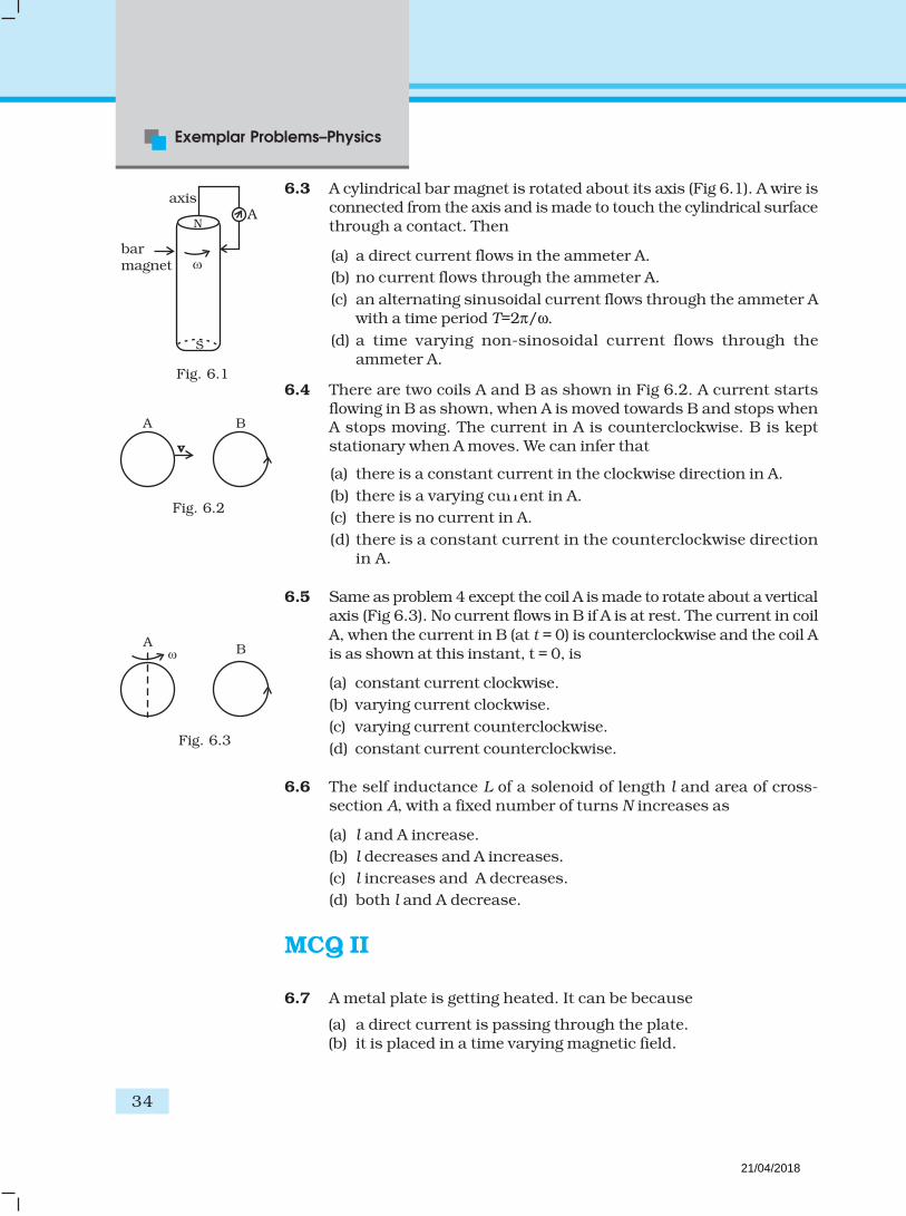
6.3 A cylindrical bar magnet is rotated about its axis (Fig 6.1). A wire isconnected from the axis and is made to touch the cylindrical surfacethrough a contact. Then
(a) a direct current flows in the ammeter A.
(b) no current flows through the ammeter A.
(c) an alternating sinusoidal current flows through the ammeter Awith a time period T=2π/ω.
(d) a time varying non-sinosoidal current flows through theammeter A.
6.4 There are two coils A and B as shown in Fig 6.2. A current startsflowing in B as shown, when A is moved towards B and stops whenA stops moving. The current in A is counterclockwise. B is keptstationary when A moves. We can infer that
(a) there is a constant current in the clockwise direction in A.
(b) there is a varying current in A.
(c) there is no current in A.
(d) there is a constant current in the counterclockwise directionin A.
6.5 Same as problem 4 except the coil A is made to rotate about a verticalaxis (Fig 6.3). No current flows in B if A is at rest. The current in coil
A, when the current in B (at t = 0) is counterclockwise and the coil Ais as shown at this instant, t = 0, is
(a) constant current clockwise.
(b) varying current clockwise.
(c) varying current counterclockwise.
(d) constant current counterclockwise.
6.6 The self inductance L of a solenoid of length l and area of cross-section A, with a fixed number of turns N increases as
(a) l and A increase.
(b) l decreases and A increases.
(c) l increases and A decreases.
(d) both l and A decrease.
MCQ II
6.7 A metal plate is getting heated. It can be because
(a) a direct current is passing through the plate.(b) it is placed in a time varying magnetic field.
AB
Fig. 6.3
barmagnet
S
Aaxis
N
A B
v
Fig. 6.2
Fig. 6.1
21/04/2018

Electromagnetic Induction
35
(c) it is placed in a space varying magnetic field, but does not varywith time.
(d) a current (either direct or alternating) is passing through theplate.
6.8 An e.m.f is produced in a coil, which is not connected to an externalvoltage source. This can be due to
(a) the coil being in a time varying magnetic field.
(b) the coil moving in a time varying magnetic field.
(c) the coil moving in a constant magnetic field.
(d) the coil is stationary in external spatially varying magnetic field,
which does not change with time.
6.9 The mutual inductance M12
of coil 1 with respect to coil 2
(a) increases when they are brought nearer.
(b) depends on the current passing through the coils.(c) increases when one of them is rotated about an axis.(d) is the same as M
21 of coil 2 with respect to coil 1.
6.10 A circular coil expands radially in a region of magnetic field andno electromotive force is produced in the coil. This can be because
(a) the magnetic field is constant.
(b) the magnetic field is in the same plane as the circular coil and
it may or may not vary.
(c) the magnetic field has a perpendicular (to the plane of the coil)
component whose magnitude is decreasing suitably.
(d) there is a constant magnetic field in the perpendicular (to the
plane of the coil) direction.
VSA
6.11 Consider a magnet surrounded by a wire with an on/off switch S(Fig 6.4). If the switch is thrown from the off position (open circuit)to the on position (closed circuit), will a current flow in the circuit?
Explain.
Barmagnet
N
Circuit closed
Barmagnet
N
Circuit open
Fig. 6.4
21/04/2018

Exemplar Problems–Physics
36
S1
S2
c
B D B
BC
B
B
P
Q B
Rv
Fig. 6.8
6.12 A wire in the form of a tightly wound solenoid is connected to a DC
source, and carries a current. If the coil is stretched so that thereare gaps between successive elements of the spiral coil, will thecurrent increase or decrease? Explain.
6.13 A solenoid is connected to a battery so that a steady current flowsthrough it. If an iron core is inserted into the solenoid, will thecurrent increase or decrease? Explain.
6.14 Consider a metal ring kept on top of a fixed solenoid (say on acarboard) (Fig 6.5). The centre of the ring coincides with the axisof the solenoid. If the current is suddenly switched on, the metal
ring jumps up. Explain
6.15 Consider a metal ring kept (supported by a cardboard) on top of afixed solenoid carrying a current I (see Fig 6.5). The centre of the
ring coincides with the axis of the solenoid. If the current in thesolenoid is switched off, what will happen to the ring?
6.16 Consider a metallic pipe with an inner radius of 1 cm. If a cylindrical
bar magnet of radius 0.8cm is dropped through the pipe, it takesmore time to come down than it takes for a similar unmagnetisedcylindrical iron bar dropped through the metallic pipe. Explain.
SA
6.17 A magnetic field in a certain region is given by ( ) ˆcosoB t= ωB k
and a coil of radius a with resistance R is placed in the x-y plane
with its centre at the origin in the magnetic field (see Fig 6.6) . Findthe magnitude and the direction of the current at (a, 0, 0) at
/2t = π ω , /t = π ω and 3 /2t = π ω .
6.18 Consider a closed loop C in a magnetic field (Fig 6.7). The fluxpassing through the loop is defined by choosing a surface whoseedge coincides with the loop and using the formula
1 1 2 2. . ...φ = + +B A Ad B d . Now if we chose two different surfaces
S1 and S
2 having C as their edge, would we get the same answer
for flux. Jusity your answer.
6.19 Find the current in the wire for the configuration shown inFig 6.8. Wire PQ has negligible resistance. B , the magneticfield is coming out of the paper. θ is a fixed angle made by PQ
travelling smoothly over two conducting parallel wiresseperated by a distance d.
ring
.........
Fig. 6.5
( ,0,0)ax
(0,0,0)
y
k
Fig. 6.6
Fig. 6.7
21/04/2018

Electromagnetic Induction
37
6.20 A (current vs time) graph of the current passing through a solenoidis shown in Fig 6.9. For which time is the back electromotive force
(u) a maximum. If the back emf at t = 3s is e, find the back emf att = 7 s, 15s and 40s. OA, AB and BC are straight line segments.
2A
1A
0
1A
2A
5 10 15 20 25 30 35 40
C
B
A
Cu
rren
t (A
)
Time (s)
Fig. 6.9
6.21 There are two coils A and B seperated by some distance. If a current
of 2 A flows through A, a magnetic flux of 10-2 Wb passes throughB (no current through B). If no current passes through A and acurrent of 1 A passes through B, what is the flux through A?
LA
6.22 A magnetic field ( ) ˆsinoB t= ωB k covers a large region where a
wire AB slides smoothly over two parallel conductors separatedby a distance d (Fig. 6.10). The wires are in the x-y plane. The wireAB (of length d) has resistance R and the parallel wires have
negligible resistance. If AB is moving with velocity v, what is thecurrent in the circuit. What is the force needed to keep the wiremoving at constant velocity?
6.23 A conducting wire XY of mass m and neglibile resistanceslides smoothly on two parallel conducting wires asshown in Fig 6.11. The closed circuit has a resistance R
due to AC. AB and CD are perfect conductors. There is amagnetic field ˆ( )B t=B k .
(i) Write down equation for the acceleration of the wire
XY.
(ii) If B is independent of time, obtain v(t) , assuming v
(0) = u0.
(iii) For (b), show that the decrease in kinetic energy of XY equalsthe heat lost in R.
y
xB
CA
O
v
Fig. 6.10
X
B
x t( )
Bl
Y
B
Dx
C
A
R
y
Fig. 6.11
21/04/2018

Exemplar Problems–Physics
38
A
D
B
I t( )
x C
L1
L + x2
A
C
B
D
B
l
PO
l l
P
B B
2l
6.24 ODBAC is a fixed rectangular conductor of negilible resistance(CO is not connnected) and OP is a conductor which rotates
clockwise with an angular velocity ω (Fig 6.12). The entire systemis in a uniform magnetic field B whose direction is along the normalto the surface of the rectangular conductor ABDC. The conductor
OP is in electric contact with ABDC. The rotating conductor has aresistance of λ per unit length. Find the current in the rotatingconductor, as it rotates by 180°.
6.25 Consider an infinitely long wire carrying a current I (t ), with
dI
dt= λ = constant. Find the current produced in the rectangular
loop of wire ABCD if its resistance is R (Fig. 6.13).
A
D
B
I t( )
xo
C
l
r
drx
Fig. 6.13
Fig. 6.14
Fig. 6.12
6.26 A rectangular loop of wire ABCD is kept close to an infinitely longwire carrying a current ( ) ( ) for 01 – /oI I t Tt Tt = ≤ ≤ and
I (0) = 0 for t > T (Fig. 6.14). Find the total charge passing througha given point in the loop, in time T. The resistance of the loop is R.
Q.27 A magnetic field B is confined to a region r a≤ and points out of
the paper (the z-axis), r = 0 being the centre of the circular region.A charged ring (charge = Q) of radius b, b > a and mass m lies in
the x-y plane with its centre at the origin. The ring is free to rotateand is at rest. The magnetic field is brought to zero in time ∆t.Find the angular velocity ω of the ring after the field vanishes.
21/04/2018
Electromagnetic Induction
39
v
B
d
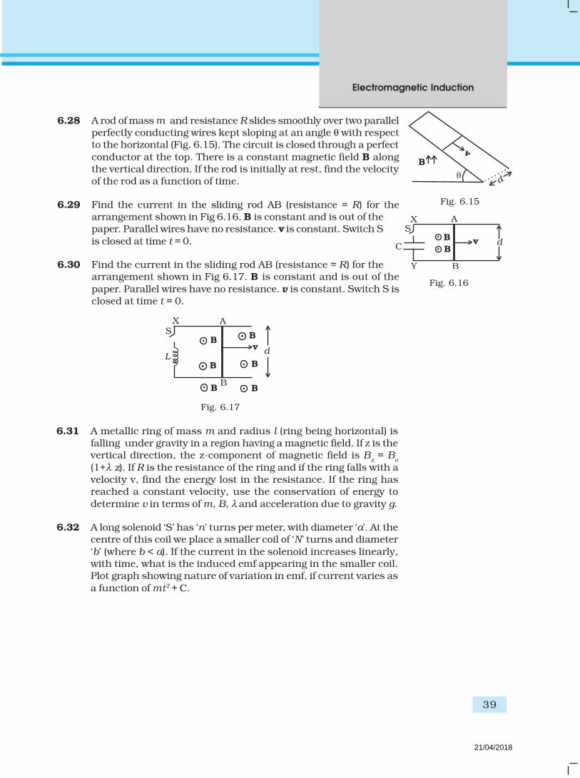
6.28 A rod of mass m and resistance R slides smoothly over two parallelperfectly conducting wires kept sloping at an angle θ with respectto the horizontal (Fig. 6.15). The circuit is closed through a perfect
conductor at the top. There is a constant magnetic field B alongthe vertical direction. If the rod is initially at rest, find the velocityof the rod as a function of time.
6.29 Find the current in the sliding rod AB (resistance = R) for thearrangement shown in Fig 6.16. B is constant and is out of thepaper. Parallel wires have no resistance. v is constant. Switch S
is closed at time t = 0.
6.30 Find the current in the sliding rod AB (resistance = R) for thearrangement shown in Fig 6.17. B is constant and is out of the
paper. Parallel wires have no resistance. v is constant. Switch S isclosed at time t = 0.
d
B
B B
B
L
B
v
AXS
B B
Fig. 6.17
Fig. 6.15
B
BC
B
dv
AX
Y
S
Fig. 6.16
6.31 A metallic ring of mass m and radius l (ring being horizontal) isfalling under gravity in a region having a magnetic field. If z is thevertical direction, the z-component of magnetic field is B
z = B
o
(1+λ z). If R is the resistance of the ring and if the ring falls with avelocity v, find the energy lost in the resistance. If the ring hasreached a constant velocity, use the conservation of energy to
determine v in terms of m, B, λ and acceleration due to gravity g.
6.32 A long solenoid ‘S’ has ‘n’ turns per meter, with diameter ‘a’. At thecentre of this coil we place a smaller coil of ‘N’ turns and diameter
‘b’ (where b < a). If the current in the solenoid increases linearly,with time, what is the induced emf appearing in the smaller coil.Plot graph showing nature of variation in emf, if current varies as
a function of mt2 + C.
21/04/2018

MCQ 1
7.1 If the rms current in a 50 Hz ac circuit is 5 A, the value of thecurrent 1/300 seconds after its value becomes zero is
(a) 5 2 A
(b) 5 3 / 2 A
(c) 5/6 A
(d) 5 / 2 A
7.2 An alternating current generator has an internal resistance Rg
and an internal reactance Xg. It is used to supply power to a
passive load consisting of a resistance Rg and a reactance XL. For
maximum power to be delivered from the generator to the load,the value of X
L is equal to
(a) zero.
(b) Xg.
(c) – Xg.
(d) Rg.
Chapter Seven
ALTERNATING
CURRENT
21/04/2018
Alternating Current
41
7.3 When a voltage measuring device is connected to AC mains, themeter shows the steady input voltage of 220V. This means
(a) input voltage cannot be AC voltage, but a DC voltage.
(b) maximum input voltage is 220V.
(c) the meter reads not v but <v2> and is calibrated to read2v< > .
(d) the pointer of the meter is stuck by some mechanical defect.
7.4 To reduce the reasonant frequency in an LCR series circuit with agenerator
(a) the generator frequency should be reduced.
(b) another capacitor should be added in parallel to the first.
(c) the iron core of the inductor should be removed.
(d) dielectric in the capacitor should be removed.
7.5 Which of the following combinations should be selected for bettertuning of an LCR circuit used for communication?
(a) R = 20 Ω, L = 1.5 H, C = 35µF.
(b) R = 25 Ω, L = 2.5 H, C = 45µF.
(c) R = 15 Ω, L = 3.5 H, C = 30µF.
(d) R = 25 Ω, L = 1.5 H, C = 45µF.
7.6 An inductor of reactance 1 Ω and a resistor of 2 Ω are connected in
series to the terminals of a 6 V (rms) a.c. source. The power dissipatedin the circuit is
(a) 8 W.
(b) 12 W.
(c) 14.4 W.
(d) 18 W.
7.7 The output of a step-down transformer is measured to be 24 Vwhen connected to a 12 watt light bulb. The value of the peak
current is
(a) 1/ 2 A.
(b) 2 A.
(c) 2 A.
(d) 2 2 A.
21/04/2018

Exemplar Problems–Physics
42
MCQ II
7.8 As the frequency of an ac circuit increases, the current first increases
and then decreases. What combination of circuit elements is mostlikely to comprise the circuit?
(a) Inductor and capacitor.
(b) Resistor and inductor.
(c) Resistor and capacitor.
(d) Resistor, inductor and capacitor.
7.9 In an alternating current circuit consisting of elements in series,the current increases on increasing the frequency of supply. Which
of the following elements are likely to constitute the circuit ?
(a) Only resistor.
(b) Resistor and an inductor.
(c) Resistor and a capacitor.
(d) Only a capacitor.
7.10 Electrical energy is transmitted over large distances at highalternating voltages. Which of the following statements is (are)correct?
(a) For a given power level, there is a lower current.
(b) Lower current implies less power loss.
(c) Transmission lines can be made thinner.
(d) It is easy to reduce the voltage at the receiving end usingstep-down transformers.
7.11 For an LCR circuit, the power transferred from the driving sourceto the driven oscillator is P = I2Z cos φ.
(a) Here, the power factor cos 0, 0.Pφ ≥ ≥
(b) The driving force can give no energy to the oscillator (P = 0) insome cases.
(c) The driving force cannot syphon out (P < 0) the energy out ofoscillator.
(d) The driving force can take away energy out of the oscillator.
7.12 When an AC voltage of 220 V is applied to the capacitor C
(a) the maximum voltage between plates is 220 V.
(b) the current is in phase with the applied voltage.
(c) the charge on the plates is in phase with the applied voltage.
(d) power delivered to the capacitor is zero.
21/04/2018

Alternating Current
43
7.13 The line that draws power supply to your house from street has
(a) zero average current.
(b) 220 V average voltage.(c) voltage and current out of phase by 90°.
(d) voltage and current possibly differing in phase φ such that
<2
φπ
.
VSA
7.14 If a LC circuit is considered analogous to a harmonically oscillatingspring block system, which energy of the LC circuit would be
analogous to potential energy and which one analogous to kineticenergy?
7.15 Draw the effective equivalent circuit of the circuit shown in
Fig 7.1, at very high frequencies and find the effective impedance.
7.16 Study the circuits (a) and (b) shown in Fig 7.2 and answer thefollowing questions.
Fig. 7.2
~
R1
C1
L1
L2
R2
C2
R3
~
R
~
R C L
(a) (b)
(a) Under which conditions would the rms currents in the twocircuits be the same?
(b) Can the rms current in circuit (b) be larger than that in (a)?
7.17 Can the instantaneous power output of an ac source ever be
negative? Can the average power output be negative?
7.18 In series LCR circuit, the plot of Imax
vs ω is shown in Fig 7.3. Findthe bandwidth and mark in the figure.
Fig. 7.1
.5 1.0 1.5 2.0
0.5
1.0
0
(rad/s)
I (A)m
Fig. 7.3
21/04/2018

Exemplar Problems–Physics
44
7.19 The alternating current in a circuit is described by the graphshown in Fig 7.4 . Show rms current in this graph.
Fig. 7.4
–3
1
0
2
–1
–2
3
T 2T
t
IA(
)v, i, P
A
B
Ct
Fig. 7.5
7.22 Both alternating current and direct current are measured inamperes. But how is the ampere defined for an alternating
current?
7.23 A coil of 0.01 henry inductance and 1 ohm resistance is connectedto 200 volt, 50 Hz ac supply. Find the impedance of the circuit
and time lag between max. alternating voltage and current.
7.24 A 60 W load is connected to the secondary of a transformer whoseprimary draws line voltage. If a current of 0.54 A flows in the
7.20 How does the sign of the phase angle φ , by which the supply
voltage leads the current in an LCR series circuit, change as thesupply frequency is gradually increased from very low to veryhigh values.
SA
7.21 A device ‘X’ is connected to an a.c source. The variation of voltage,current and power in one complete cycle is shown in Fig 7.5.
(a) Which curve shows power consumption over a full cycle?
(b) What is the average power consumption over a cycle?
(c) Identify the device ‘X’.
21/04/2018
Alternating Current
45
load, what is the current in the primary coil? Comment on thetype of transformer being used.
7.25 Explain why the reactance provided by a capacitor to analternating current decreases with increasing frequency.
7.26 Explain why the reactance offered by an inductor increases with
increasing frequency of an alternating voltage.
LA
7.27 An electrical device draws 2kW power from AC mains (voltage
223V (rms) = 50,000 V). The current differs (lags) in phase by
–3tan
4φ φ
= as compared to voltage. Find (i) R, (ii) X
C – X
L, and
(iii) IM. Another device has twice the values for R, X
C and X
L. How
are the answers affected?
7.28 1MW power is to be delivered from a power station to a town10 km away. One uses a pair of Cu wires of radius 0.5 cm for thispurpose. Calculate the fraction of ohmic losses to power
transmitted if
(i) power is transmitted at 220V. Comment on the feasibility ofdoing this.
(ii) a step-up transformer is used to boost the voltage to11000 V, power transmitted, then a step-down transfomer isused to bring voltage to 220 V.
–8( 1.7 10 SI unit)Cuρ = ×
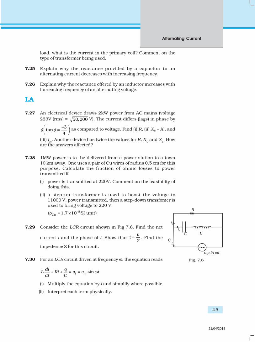
7.29 Consider the LCR circuit shown in Fig 7.6. Find the net
current i and the phase of i. Show that v
iZ
= . Find the
impedence Z for this circuit.
7.30 For an LCR circuit driven at frequency ω, the equation reads
sini m
di qL Ri v v t
dt C+ + = = ω
(i) Multiply the equation by i and simplify where possible.
(ii) Interpret each term physically.
R
LC
i2
i1
i
v sin tm
C
Fig. 7.6
21/04/2018

Exemplar Problems–Physics
46
C
R L
Fig. 7.7
(iii) Cast the equation in the form of a conservation of energystatement.
(iv) Intergrate the equation over one cycle to find that the phasedifference between v and i must be acute.
7.31 In the LCR circuit shown in Fig 7.7, the ac driving voltage is
v = vm sin ωt.
(i) Write down the equation of motion for q (t ).
(ii) At t = t0, the voltage source stops and R is short circuited. Now
write down how much energy is stored in each of L and C.
(iii) Describe subsequent motion of charges.
21/04/2018

MCQ I
8.1 One requires 11eV of energy to dissociate a carbon monoxidemolecule into carbon and oxygen atoms. The minimum frequencyof the appropriate electromagnetic radiation to achieve the
dissociation lies in
(a) visible region.
(b) infrared region.
(c) ultraviolet region.
(d) microwave region.
8.2 A linearly polarized electromagnetic wave given as
( )ˆcos – toE kz ω=E i is incident normally on a perfectly reflecting
infinite wall at z = a. Assuming that the material of the wall is opticallyinactive, the reflected wave will be given as
(a) ( )ˆ– cos – tr oE kz ω=E i .
(b) ( )ˆcos toE kz ω= +E ir
.
Chapter Eight
ELECTROMAGNETIC
WAVES
21/04/2018

Exemplar Problems–Physics
48
(c) ( )ˆ– cos toE kz ω= +E ir
.
(d) ( )ˆsin – toE kz ω=E ir
.
8.3 Light with an energy flux of 20 W/cm2 falls on a non-reflectingsurface at normal incidence. If the surface has an area of 30 cm2.the total momentum delivered (for complete absorption) during
30 minutes is
(a) 36 × 10–5 kg m/s.
(b) 36 × 10–4 kg m/s.
(c) 108 × 104 kg m/s.
(d) 1.08 × 10⁷ kg m/s.
8.4 The electric field intensity produced by the radiations coming from100 W bulb at a 3 m distance is E. The electric field intensityproduced by the radiations coming from 50 W bulb at the same
distance is
(a)2
E .
(b) 2E.
(c) .2
E
(d) 2 .E
8.5 If E and B represent electric and magnetic field vectors of theelectromagnetic wave, the direction of propagation of electromagneticwave is along
(a) E.
(b) B.
(c) B × E.
(d) E × B.
8.6 The ratio of contributions made by the electric field and magnetic
field components to the intensity of an EM wave is
(a) c : 1
(b) c2 : 1
(c) 1 : 1
(d) :1c
8.7 An EM wave radiates outwards from a dipole antenna, with E0 as
the amplitude of its electric field vector. The electric field E0 which
21/04/2018

Electromagnetic Waves
49
transports significant energy from the source falls off as
(a) 3
1
r
(b) 2
1
r
(c)1
r(d) remains constant.
MCQ II
8.8 An electromognetic wave travels in vacuum along
z direction: ( ) ( )ˆ ˆ cos1 2E + E kz tω= −E i j . Choose the correct options
from the following:
(a) The associated magnetic field is given as
( )1 ˆ ˆc 1 2E – E=B i j cos (kz-ωt).
(b) The associated magnetic field is given as
( )ˆ ˆ1 2
1E – E
c=B i j cos (kz-ωt).
(c) The given electromagnetic field is circularly polarised.
(d) The given electromagnetic wave is plane polarised.
8.9 An electromagnetic wave travelling along z-axis is given as:
=0
E E cos (kz - ωt.). Choose the correct options from the following;
(a) The associated magnetic field is given as 1 1ˆ ˆ= × = ( × )c ω
B k E k E .
(b) The electromagnetic field can be written in terms of the
associated magnetic field as E = c ˆ( )×B k .
(c) ˆ ˆ. 0, 0= =k E k B..
(d) ˆ ˆ0, 0× = × =k E k B .
8.10 A plane electromagnetic wave propagating along x direction canhave the following pairs of E and B
(a) Ex, B
y.
(b) Ey, B
z.
(c) Bx, E
y.
(d) Ez, B
y.
21/04/2018

Exemplar Problems–Physics
50
8.11 A charged particle oscillates about its mean equilibrium positionwith a frequency of 109 Hz. The electromagnetic waves produced:
(a) will have frequency of 109 Hz.
(b) will have frequency of 2 × 10⁹ Hz.
(c) will have a wavelength of 0.3 m.
(d) fall in the region of radiowaves.
8.12 The source of electromagnetic waves can be a charge
(a) moving with a constant velocity.
(b) moving in a circular orbit.
(c) at rest.
(d) falling in an electric field.
8.13 An EM wave of intensity I falls on a surface kept in vacuum and
exerts radiation pressure p on it. Which of the following are true?
(a) Radiation pressure is I/c if the wave is totally absorbed.(b) Radiation pressure is I/c if the wave is totally reflected.
(c) Radiation pressure is 2I/c if the wave is totally reflected.(b) Radiation pressure is in the range I/c < p < 2I/c for real surfaces.
VSA
8.14 Why is the orientation of the portable radio with respect tobroadcasting station important?
8.15 Why does microwave oven heats up a food item containing water
molecules most efficiently?
8.16 The charge on a parallel plate capacitor varies as q = q0 cos 2πνt.
The plates are very large and close together (area = A,
separation = d). Neglecting the edge effects, find the displacementcurrent through the capacitor?
8.17 A variable frequency a.c source is connected to a capacitor. How
will the displacement current change with decrease in frequency?
8.18 The magnetic field of a beam emerging from a filter facing afloodlight is given by
B0 = 12 × 10–8 sin (1.20 × 10⁷ z – 3.60 × 10¹⁵ t) T.
What is the average intensity of the beam?
8.19 Poynting vectors S is defined as a vector whose magnitude is equal
to the wave intensity and whose direction is along the direction of
wave propogation. Mathematically, it is given by 0
1
µ= ×S E B .
Show the nature of S vs t graph.
21/04/2018

Electromagnetic Waves
51
8.20 Professor C.V Raman surprised his students by suspending freelya tiny light ball in a transparent vacuum chamber by shining a
laser beam on it. Which property of EM waves was he exhibiting?Give one more example of this property.
SA
8.21 Show that the magnetic field B at a point in between the plates of
a parallel-plate capacitor during charging is 0 d
2 dr E
t
ε µ (symbols
having usual meaning).
8.22 Electromagnetic waves with wavelength
(i) λ1 is used in satellite communication.
(ii) λ2 is used to kill germs in water purifies.
(iii) λ3 is used to detect leakage of oil in underground pipelines.
(iv) λ4 is used to improve visibility in runways during fog and mist
conditions.
(a) Identify and name the part of electromagnetic spectrum towhich these radiations belong.
(b) Arrange these wavelengths in ascending order of their
magnitude.
(c) Write one more application of each.
8.23 Show that average value of radiant flux density ‘S’ over a single
period ‘T’ is given by 20
0
1S
2cE=
µ.
8.24 You are given a 2µF parallel plate capacitor. How would youestablish an instantaneous displacement current of 1mA in the
space between its plates?
8.25 Show that the radiation pressure exerted by an EM wave ofintensity I on a surface kept in vacuum is I/c.
8.26 What happens to the intensity of light from a bulb if thedistance from the bulb is doubled? As a laser beam travels acrossthe length of a room, its intensity essentially remains constant.
21/04/2018

Exemplar Problems–Physics
52
xV
y
a
Z
What geomatrical characteristic of LASER beam is responsible forthe constant intensity which is missing in the case of light from
the bulb?
8.27 Even though an electric field E exerts a force qE on a chargedparticle yet the electric field of an EM wave does not contribute to
the radiation pressure (but transfers energy). Explain.
LA
8.28 An infinitely long thin wire carrying a uniform linear static charge
density λ is placed along the z-axis (Fig. 8.1). The wire is set into
motion along its length with a uniform velocity ˆzv=v k . Calculate
the poynting vector o
1( ).= ×
µS E B
8.29 Sea water at frequency ν = 4 × 10⁸ Hz has permittivity ε ≈ 80 εo,
permeability µ ≈ µo and resistivity ρ = 0.25 Ω–m. Imagine a parallel
plate capacitor immersed in sea water and driven by an alternatingvoltage source V(t) = V
o sin (2π νt). What fraction of the conduction
current density is the displacement current density?
8.30 A long straight cable of length l is placed symmetrically alongz-axis and has radius a(<<l). The cable consists of a thin wire and
a co-axial conducting tube. An alternating current I(t) = Io sin (2πνt)
flows down the central thin wire and returns along the co-axialconducting tube. The induced electric field at a distance s from
the wire inside the cable is o oˆ( , ) cos(2 ) In
ss t I t
a
= µ ν πν
E k.
(i) Calculate the displacement current density inside the cable.
(ii) Integrate the displacement current density across the cross-section of the cable to find the total displacement current Id.
(iii) Compare the conduction current I0 with the dispalcement
current d
oI .
8.31 A plane EM wave travelling in vacuum along z direction is given
by 0ˆsin( – )E kz tω=E i and ˆsin( – )0B kz tω=B j .
(i) Evaluate . E dl over the rectangular loop 1234 shown in
Fig 8.2.
(ii) Evaluate .B ds over the surface bounded by loop 1234.
Fig. 8.1
21/04/2018

Electromagnetic Waves
53
(iii) Use equation B–d
.dt
= E dlφ
to prove 0
0
cE
B= .
(iv) By using similar process and the equation
E0 0
d. ,
dI
t
φµ ε= + B dl prove that
0 0
1c =
µ ε
8.32 A plane EM wave travelling along z direction is described
by 0
ˆsin( – )E kz t=E iω and 0
ˆsin( – )B kz t=B jω . Show
that
(i) The average energy density of the wave is given by
22 0
av 0 0
0
B1 1
4 4u E= +ε
µ.
(ii) The time averaged intensity of the wave is given by
2av 0 0
1c .
2I Eε=
h
4 3
21
x
y
z
Fig. 8.2
21/04/2018

MCQ I
9.1 A ray of light incident at an angle θ on a refracting face of a prism
emerges from the other face normally. If the angle of the prism is 5°and the prism is made of a material of refractive index 1.5, the angleof incidence is
(a) 7.5°.
(b) 5°.
(c) 15°.
(d) 2.5°.
9.2 A short pulse of white light is incident from air to a glass slab at
normal incidence. After travelling through the slab, the first colourto emerge is
(a) blue.
(b) green.
(c) violet.
(d) red.
Chapter Nine
RAY OPTICS AND
OPTICAL
INSTRUMENTS
21/04/2018

Ray Optics and Optical Instruments
55
9.3 An object approaches a convergent lens from the left of the lenswith a uniform speed 5 m/s and stops at the focus. The image
(a) moves away from the lens with an uniform speed 5 m/s.
(b) moves away from the lens with an uniform accleration.
(c) moves away from the lens with a non-uniform acceleration.
(d) moves towards the lens with a non-uniform acceleration.
9.4 A passenger in an aeroplane shall
(a) never see a rainbow.
(b) may see a primary and a secondary rainbow as concentric circles.
(c) may see a primary and a secondary rainbow as concentric arcs.
(d) shall never see a secondary rainbow.
9.5 You are given four sources of light each one providing a light of asingle colour – red, blue, green and yellow. Suppose the angle ofrefraction for a beam of yellow light corresponding to a particular
angle of incidence at the interface of two media is 90°. Which of thefollowing statements is correct if the source of yellow light is replacedwith that of other lights without changing the angle of incidence?
(a) The beam of red light would undergo total internal reflection.
(b) The beam of red light would bend towards normal while it gets
refracted through the second medium.
(c) The beam of blue light would undergo total internal reflection.
(d) The beam of green light would bend away from the normal as itgets refracted through the second medium.
9.6 The radius of curvature of the curved surface of a plano-convexlens is 20 cm. If the refractive index of the material of the lens be
1.5, it will
(a) act as a convex lens only for the objects that lie on its curvedside.
(b) act as a concave lens for the objects that lie on its curved side.
(c) act as a convex lens irrespective of the side on which the objectlies.
(d) act as a concave lens irrespective of side on which the object lies.
9.7 The phenomena involved in the reflection of radiowaves by
ionosphere is similar to
(a) reflection of light by a plane mirror.
(b) total internal reflection of light in air during a mirage.
(c) dispersion of light by water molecules during the formation of a
rainbow.
(d) scattering of light by the particles of air.
21/04/2018

Exemplar Problems–Physics
56
1
2
C
P3
F
Q 4
9.8 The direction of ray of light incident on a concave mirror is shownby PQ while directions in which the ray would travel after reflection
is shown by four rays marked 1, 2, 3 and 4(Fig 9.1). Which of the four rays correctly shows the direction ofreflected ray?
(a) 1
(b) 2
(c) 3
(d) 4
9.9 The optical density of turpentine is higher than that of water while
its mass density is lower. Fig 9.2. shows a layer of turpentinefloating over water in a container. For which one of the four raysincident on turpentine in Fig 9.2, the path shown is correct?
(a) 1
(b) 2
(c) 3
(d) 4
1 2 3 4
Air
Turpentine
Water
9.10 A car is moving with at a constant speed of 60 km h–1 on a straightroad. Looking at the rear view mirror, the driver finds that the car
following him is at a distance of 100 m and is approaching with aspeed of 5 km h –1. In order to keep track of the car in the rear, thedriver begins to glance alternatively at the rear and side mirror of
his car after every 2 s till the other car overtakes. If the two carswere maintaining their speeds, which of the following statement(s) is/are correct?
(a) The speed of the car in the rear is 65 km h–1.
(b) In the side mirror the car in the rear would appear to approachwith a speed of 5 km h–1 to the driver of the leading car.
(c) In the rear view mirror the speed of the approaching car wouldappear to decrease as the distance between the cars decreases.
(d) In the side mirror, the speed of the approaching car wouldappear to increase as the distance between the cars decreases.
Fig. 9.1
Fig. 9.2
21/04/2018

Ray Optics and Optical Instruments
57
9.11 There are certain material developed in laboratories which have anegative refractive index (Fig. 9.3). A ray incident from air (medium 1)
into such a medium (medium 2) shall follow a path given by
i
r
1
2
i
r
1
2
1
2
(a) (b)
(d)(c)
i r 1
2
MCQ II
9.12 Consider an extended object immersed in water contained in aplane trough. When seen from close to the edge of the trough theobject looks distorted because
(a) the apparent depth of the points close to the edge are nearerthe surface of the water compared to the points away from theedge.
(b) the angle subtended by the image of the object at the eye issmaller than the actual angle subtended by the object in air.
(c) some of the points of the object far away from the edge maynot be visible because of total internal reflection.
(d) water in a trough acts as a lens and magnifies the object.
9.13 A rectangular block of glass ABCD has a refractive index 1.6.A pin is placed midway on the face AB (Fig. 9.4). When observedfrom the face AD, the pin shall
(a) appear to be near A.
(b) appear to be near D.
(c) appear to be at the centre of AD.
(d) not be seen at all.
9.14 Between the primary and secondary rainbows, there is a darkband known as Alexandar’s dark band. This is because
(a) light scattered into this region interfere destructively.(b) there is no light scattered into this region.
A B
D C
Fig. 9.3
Fig. 9.4
21/04/2018

Exemplar Problems–Physics
58
(c) light is absorbed in this region.
(d) angle made at the eye by the scattered rays with respect to theincident light of the sun lies between approximately 42° and50°.
9.15 A magnifying glass is used, as the object to be viewed can bebrought closer to the eye than the normal near point. This
results in
(a) a larger angle to be subtended by the object at the eye andhence viewed in greater detail.
(b) the formation of a virtual erect image.
(c) increase in the field of view.
(d) infinite magnification at the near point.
9.16 An astronomical refractive telescope has an objective of focal length20m and an eyepiece of focal length 2cm.
(a) The length of the telescope tube is 20.02m.(b) The magnification is 1000.(c) The image formed is inverted.
(d) An objective of a larger aperture will increase the brightnessand reduce chromatic aberration of the image.
VSA
9.17 Will the focal length of a lens for red light be more, same or lessthan that for blue light?
9.18 The near vision of an average person is 25cm. To view an object
with an angular magnification of 10, what should be the power ofthe microscope?
9.19 An unsymmetrical double convex thin lens forms the image of a
point object on its axis. Will the position of the image change ifthe lens is reversed?
9.20 Three immiscible liquids of densities d1 > d
2 > d
3 and refractive
indices µ1 > µ
2 > µ
3 are put in a beaker. The height of each liquid
column is 3
h. A dot is made at the bottom of the beaker. For near
normal vision, find the apparent depth of the dot.
9.21 For a glass prism (µ = 3 ) the angle of minimum deviation is
equal to the angle of the prism. Find the angle of the prism.
21/04/2018

Ray Optics and Optical Instruments
59
SA
9.22 A short object of length L is placed along the principal axis of a
concave mirror away from focus. The object distance is u. If themirror has a focal length f, what will be the length of the image?You may take L <<|v - f|.
9.23 A circular disc of radius ‘R ’ is placed co-axially and horizontallyinside an opaque hemispherical bowl of radius ‘a’ (Fig. 9.5). Thefar edge of the disc is just visible when viewed from the edge of the
bowl. The bowl is filled with transparent liquid of refractive indexµ and the near edge of the disc becomes just visible. How far belowthe top of the bowl is the disc placed?
9.24 A thin convex lens of focal length 25 cm is cut into two pieces0.5 cm above the principal axis. The top part is placed at (0,0) andan object placed at (–50 cm, 0). Find the coordinates of the image.
9.25 In many experimental set-ups the source and screen are fixed ata distance say D and the lens is movable. Show that there are twopositions for the lens for which an image is formed on the screen.
Find the distance between these points and the ratio of the imagesizes for these two points.
9.26 A jar of height h is filled with a transparent liquid of refractive
index µ (Fig. 9.6). At the centre of the jar on the bottom surface isa dot. Find the minimum diameter of a disc, such that when placedon the top surface symmetrically about the centre, the dot is
invisible.
O
90 -
A BC
id
Ma a
R R
Fig. 9.5
Fig. 9.6
d
O
hi i
9.27 A myopic adult has a far point at 0.1 m. His power of accomodationis 4 diopters. (i) What power lenses are required to see distant
21/04/2018

Exemplar Problems–Physics
60
objects? (ii) What is his near point without glasses? (iii) What ishis near point with glasses? (Take the image distance from the
lens of the eye to the retina to be 2 cm.)
LA
9.28 Show that for a material with refractive index µ ≥ 2 , light incident
at any angle shall be guided along a length perpendicular to theincident face.
9.29 The mixture a pure liquid and a solution in a long vertical column
(i.e, horizontal dimensions << vertical dimensions) producesdiffusion of solute particles and hence a refractive index gradientalong the vertical dimension. A ray of light entering the column at
right angles to the vertical is deviated from its original path. Findthe deviation in travelling a horizontal distance d << h, the heightof the column.
9.30 If light passes near a massive object, the gravitational interactioncauses a bending of the ray. This can be thought of as happeningdue to a change in the effective refrative index of the medium
given by
n(r) = 1 + 2 GM/rc2
where r is the distance of the point of consideration from the centre
of the mass of the massive body, G is the universal gravitationalconstant, M the mass of the body and c the speed of light invacuum. Considering a spherical object find the deviation of the
ray from the original path as it grazes the object.
9.31 An infinitely long cylinder of radius R is made of an unusual exoticmaterial with refractive index –1 (Fig. 9.7). The cylinder is placed
between two planes whose normals are along the y direction. Thecenter of the cylinder O lies along the y-axis. A narrow laser beamis directed along the y direction from the lower plate. The laser
source is at a horizontal distance x from the diameter in they direction. Find the range of x such that light emitted from thelower plane does not reach the upper plane.
9.32 (i) Consider a thin lens placed between a source (S) and anobserver (O) (Fig. 9.8). Let the thickness of the lens vary as
2
0( ) –α
=b
w b w , where b is the verticle distance from the pole.
w0 is a constant. Using Fermat’s principle i.e. the time of transit
y
x
i
R
x
o
i
r
Fig. 9.7
21/04/2018

Ray Optics and Optical Instruments
61
for a ray between the source and observer is anextremum, find the condition that all paraxial rays
starting from the source will converge at a point Oon the axis. Find the focal length.
(ii) A gravitational lens may be assumed to have a varyingwidth of the form
21( )
kw b k ln
b
=
b
min < b < b
max
21
min
kk ln
b
=
b < b
min
Show that an observer will see an image of a point object as aring about the center of the lens with an angular radius
( ) 1–1u
knv
u vβ =
+.
P1
S u v O
b
Fig. 9.8
21/04/2018

MCQ I
10.1 Consider a light beam incident from air to a glass slab at Brewster’s
angle as shown in Fig. 10.1.
A polaroid is placed in the path of the emergent ray at point Pand rotated about an axis passing through the centre
and perpendicular to the plane of the polaroid.
(a) For a particular orientation there shall be darknessas observed through the polaoid.
(b) The intensity of light as seen through the polaroidshall be independent of the rotation.
(c) The intensity of light as seen through the Polaroidshall go through a minimum but not zero for two
orientations of the polaroid.
(d) The intensity of light as seen through the polaroid shall
go through a minimum for four orientations of thepolaroid.
10.2 Consider sunlight incident on a slit of width 104 A. The imageseen through the slit shall
Chapter Ten
WAVE OPTICS
PFig. 10.1
21/04/2018
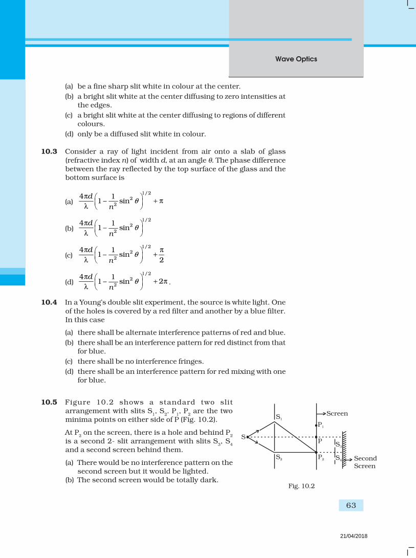
Wave Optics
63
(a) be a fine sharp slit white in colour at the center.
(b) a bright slit white at the center diffusing to zero intensities atthe edges.
(c) a bright slit white at the center diffusing to regions of differentcolours.
(d) only be a diffused slit white in colour.
10.3 Consider a ray of light incident from air onto a slab of glass
(refractive index n) of width d, at an angle θ. The phase differencebetween the ray reflected by the top surface of the glass and thebottom surface is
(a)
1/22
2
4 11 – sin θ
π + π
λ d
n
(b)
1/22
2
4 11 – sin
d
nθ
π
λ
(c)
1/22
2
4 11 – sin
2
d
nθ
π π +
λ
(d)
1/22
2
4 121 – sin
d
nθ
π + π
λ .
10.4 In a Young’s double slit experiment, the source is white light. One
of the holes is covered by a red filter and another by a blue filter.In this case
(a) there shall be alternate interference patterns of red and blue.
(b) there shall be an interference pattern for red distinct from thatfor blue.
(c) there shall be no interference fringes.
(d) there shall be an interference pattern for red mixing with onefor blue.
10.5 Figure 10.2 shows a standard two slitarrangement with slits S
1, S
2. P
1, P
2 are the two
minima points on either side of P (Fig. 10.2).
At P2 on the screen, there is a hole and behind P
2
is a second 2- slit arrangement with slits S3, S
4
and a second screen behind them.
(a) There would be no interference pattern on thesecond screen but it would be lighted.
(b) The second screen would be totally dark.
Screen
P1
P2
S3
S4
S1
S2 Second
Screen
SP
Fig. 10.2
21/04/2018

Exemplar Problems–Physics
64
(c) There would be a single bright point on the second screen.(d) There would be a regular two slit pattern on the second screen.
MCQ II
10.6 Two source S1 and S
2 of intensity I
1 and I
2 are placed in front of a
screen [Fig. 10.3 (a)]. The patteren of intensity distribution seenin the central portion is given by Fig. 10.3 (b).
In this case which of the following statements are true.
(a) S1 and S
2 have the same intensities.
(b) S1 and S
2 have a constant phase difference.
(c) S1 and S
2 have the same phase.
(d) S1 and S
2 have the same wavelength.
10.7 Consider sunlight incident on a pinhole of width 103A. The image
of the pinhole seen on a screen shall be
(a) a sharp white ring.
(b) different from a geometrical image.
(c) a diffused central spot, white in colour.
(d) diffused coloured region around a sharp central white spot.
10.8 Consider the diffraction patern for a small pinhole. As the size ofthe hole is increased
(a) the size decreases.
(b) the intensity increases.
(c) the size increases.
(d) the intensity decreases.
10.9 For light diverging from a point source
(a) the wavefront is spherical.
(b) the intensity decreases in proportion to the distance squared.
(c) the wavefront is parabolic.
(d) the intensity at the wavefront does not depend on the distance.
VSA
10.10 Is Huygen’s principle valid for longitudunal sound waves?
10.11 Consider a point at the focal point of a convergent lens. Another
convergent lens of short focal length is placed on the other side.What is the nature of the wavefronts emerging from the final image?
10.12 What is the shape of the wavefront on earth for sunlight?
xx = 0
Fig. 10.3 (b)
x
S1
S2
Fig. 10.3 (a)
21/04/2018

Wave Optics
65
10.13 Why is the diffraction of sound waves more evident in dailyexperience than that of light wave?
10.14 The human eye has an approximate angular resolution of
–45.8 10= ×φ rad and a typical photoprinter prints a minimum
of 300 dpi (dots per inch, 1 inch = 2.54 cm). At what minimaldistance z should a printed page be held so that one does not see
the individual dots.
10.15 A polariod (I) is placed in front of a monochromatic source.Another polatiod (II) is placed in front of this polaroid (I) and
rotated till no light passes. A third polaroid (III) is now placed inbetween (I) and (II). In this case, will light emerge from (II). Explain.
SA
10.16 Can reflection result in plane polarised light if the light is incidenton the interface from the side with higher refractive index?
10.17 For the same objective, find the ratio of the least separation
between two points to be distinguished by a microscope for light
of 5000 A
and electrons accelerated through 100V used as the
illuminating substance.
10.18 Consider a two slit interference arrangements (Fig. 10.4) suchthat the distance of the screen from the slits is half the distancebetween the slits. Obtain the value of D in terms of λ such
that the first minima on the screen falls at a distance D from thecentre O.
S1
P
S
S2
1
2
Fig. 10.4
Fig. 10.5
S1 T1
P
O
T2
S
Source
C
S2
Screen
OP = x
CO = D
S1C = CS
2 = D
LA
10.19 Figure 10.5 shown a two slit arrangement with a source which
emits unpolarised light. P is a polariser with axis whose directionis not given. If I
0 is the intensity of the principal maxima when no
polariser is present, calculate in the present case, the intensity of
the principal maxima as well as of the first minima.
21/04/2018

Exemplar Problems–Physics
66
R1 A B C
D
/2
/2 /2
R2
10.20
Screen
P1
S1
S2
AC
O
Ld
=/4
AC = CO = D, S1C = S
2C = d << D
A small transparent slab containing material of 1.5µ = is placed
along AS2 (Fig.10.6). What will be the distance from O of the
principal maxima and of the first minima on either side of the
principal maxima obtained in the absence of the glass slab. .
10.21 Four identical monochromatic sources A,B,C,D as shown in the(Fig.10.7) produce waves of the same wavelength λ and are
coherent. Two receiver R1 and R
2 are at great but equal distaces
from B.
(i) Which of the two receivers picks up the larger signal?
(ii) Which of the two receivers picks up the larger signal when Bis turned off?
(iii) Which of the two receivers picks up the larger signal when D
is turned off?(iv) Which of the two receivers can distinguish which of the sources
B or D has been turned off?
Fig. 10.6
Fig. 10.7
R1B = d = R
2B
AB = BC = BD = λ/2
21/04/2018
Wave Optics
67
10.22 The optical properties of a medium are governed by the relative
permitivity ( )r
ε and relative permeability (µr ). The refractive index
is defined as r r
n.µ ε = For ordinary material rε > 0 and µ
r > 0 and
the positive sign is taken for the square root. In 1964, a Russian
scientist V. Veselago postulated the existence of material with rε
< 0 and µr < 0. Since then such ‘metamaterials’ have been
produced in the laboratories and their optical properties studied.
For such materials r r
n –= µ ε . As light enters a medium of such
refractive index the phases travel away from the direction ofpropagation.
(i) According to the description above show that if rays of light
enter such a medium from air (refractive index =1) at an angleθ in 2nd quadrant, them the refracted beam is in the 3rd quadrant.
(ii) Prove that Snell’s law holds for such a medium.
10.23 To ensure almost 100 per cent transmittivity, photographic lensesare often coated with a thin layer of dielectric material. The refractiveindex of this material is intermediated between that of air and glass
(which makes the optical element of the lens). A typically useddielectric film is MgF
2 (n = 1.38). What should the thickness of the
film be so that at the center of the visible speetrum (5500 A
) there
is maximum transmission.
21/04/2018

Exemplar Problems–Physics
MCQ I
11.1 A particle is dropped from a height H. The de Broglie wavelengthof the particle as a function of height is proportional to
(a) H
(b) H 1/2
(c) H0
(b) H –1/2
11.2 The wavelength of a photon needed to remove a proton from anucleus which is bound to the nucleus with 1 MeV energy is nearly
(a) 1.2 nm
(b) 1.2 × 10⁻³ nm
(c) 1.2 × 10⁻⁶ nm
(d) 1.2 × 101 nm
11.3 Consider a beam of electrons (each electron with energy E0) incident
on a metal surface kept in an evacuated chamber. Then
Chapter Eleven
DUAL NATURE OF
RADIATION AND
MATTER
21/04/2018

Dual Nature of Radiation
and Matter
69
(a) no electrons will be emitted as only photons can emit electrons.
(b) electrons can be emitted but all with an energy, E0.
(c) electrons can be emitted with any energy, with a maximum of
E0 – φ (φ is the work function).
(d) electrons can be emitted with any energy, with a maximum of
E0.
11.4 Consider Fig. 11.7 in the NCERT text book of physics for Class
XII. Suppose the voltage applied to A is increased. The diffractedbeam will have the maximum at a value of θ that
(a) will be larger than the earlier value.
(b) will be the same as the earlier value.
(c) will be less than the earlier value.
(d) will depend on the target.
11.5 A proton, a neutron, an electron and an α-particle have sameenergy. Then their de Broglie wavelengths compare as
(a) λp = λ
n > λ
e > λ
α
(b) λα < λ
p = λ
n > λ
e
(c) λe < λ
p = λ
n > λ
α
(d) λe = λ
p = λ
n = λ
α
11.6 An electron is moving with an initial velocity 0ˆv=v i and is in a
magnetic field 0ˆB=B j . Then it’s de Broglie wavelength
(a) remains constant.
(b) increases with time.
(c) decreases with time.
(d) increases and decreases periodically.
11.7 An electron (mass m ) with an initial velocity 0 0ˆ( 0)v v= >v i is in
an electric field 0 0ˆ– ( constant 0 )E E= = >E i . It’s de Broglie
wavelength at time t is given by
(a) 0
0
0
1eE t
m v
+
λ
(b)0
00
1eE t
mv
+
λ
(c) λ0
(d) λ0t.
21/04/2018

Exemplar Problems–Physics
70
11.8 An electron (mass m) with an initial velocity 0ˆv=v i is in an
electric field 0ˆE=E j . If λ
0 = h/mv
0, it’s de Breoglie wavelength at
time t is given by
(a) λ0
(b)
2 2 20
0 2 20
1e E t
m vλ +
(c)0
2 2 20
2 20
1e E t
m v
λ
+
(d)0
2 2 20
2 20
1e E t
m v
λ
+
MCQ II
11.9 Relativistic corrections become neccssary when the expression
for the kinetic energy 21
2mv , becomes comparable with mc2,
where m is the mass of the particle. At what de Broglie wavelengthwill relativistic corrections become important for an electron?
(a) λ =10nm
(b) λ =10–1nm
(c) λ =10–4nm
(d) λ =10–6nm
11.10 Two particles A1 s
and A2 of masses m
1, m
2 (m
1 > m
2) have the same
de Broglie wavelength. Then
(a) their momenta are the same.
(b) their energies are the same.
(c) energy of A1 is less than the energy of A
2.
(d) energy of A1 is more than the energy of A
2.
11.11 The de Broglie wavelength of a photon is twice the de Broglie
wavelength of an electron. The speed of the electron is 100
e
cv = .
Then
21/04/2018

Dual Nature of Radiation
and Matter
71
(a) –410e
p
E
E=
(b) –210e
p
E
E=
(c) –210e
e
p
m c=
(d) –410e
e
p
m c= .
11.12 Photons absorbed in matter are converted to heat. A sourceemitting n photon/sec of frequency ν is used to convert 1kg ofice at 0°C to water at 0°C. Then, the time T taken for the
conversion
(a) decreases with increasing n, with ν fixed.
(b) decreases with n fixed, ν increasing
(c) remains constant with n and ν changing such that
nν = constant.
(d) increases when the product nν increases.
11.13 A particle moves in a closed orbit around the origin, due to aforce which is directed towards the origin. The de Broglie
wavelength of the particle varies cyclically between two values λ1,
λ2 with λ
1>λ
2. Which
of the following statement are true?
(a) The particle could be moving in a circular orbit with origin as
centre
(b) The particle could be moving in an elliptic orbit with origin asits focus.
(c) When the de Broglie wave length is λ1, the particle is nearer
the origin than when its value is λ2.
(d) When the de Broglic wavelength is λ2, the particle is nearer
the origin than when its value is λ1.
VSA
11.14 A proton and an α-particle are accelerated, using the same
potential difference. How are the deBroglie wavelengths λp and
λa related to each other?
11.15 (i) In the explanation of photo electric effect, we asssume one
photon of frequency ν collides with an electron and transfers
21/04/2018

Exemplar Problems–Physics
72
electron
light
metal
its energy. This leads to the equation for the maximum energyE
max of the emitted electron as
Emax
= hν – φ0
where φ0
is the work function of the metal. If an electronabsorbs 2 photons (each of frequency ν ) what will be the
maximum energy for the emitted electron?
(ii) Why is this fact (two photon absorption) not taken intoconsideration in our discussion of the stopping potential?
11.16 There are materials which absorb photons of shorter wavelengthand emit photons of longer wavelength. Can there be stable
substances which absorb photons of larger wavelength and emitlight of shorter wavelength.
11.17 Do all the electrons that absorb a photon come out as
photoelectrons?
11.18 There are two sources of light, each emitting with a power of100 W. One emits X-rays of wavelength 1nm and the other visible
light at 500 nm. Find the ratio of number of photons of X-rays tothe photons of visible light of the given wavelength?
SA
11.19 Consider Fig.11.1 for photoemission.
How would you reconcile with momentum-conservation? Notelight (photons) have momentum in a different direction than the
emitted electrons.
11.20 Consider a metal exposed to light of wavelength 600 nm. Themaximum energy of the electron doubles when light of
wavelength 400 snm is used. Find the work function in eV.
11.21 Assuming an electron is confined to a 1nm wide region , find theuncertainty in momentum using Heisenberg Uncertainty
principle (Ref Eq 11.12 of NCERT Textbook). You can assume
the uncertainty in position ∆x as 1nm. Assuming p p∆ , find
the energy of the electron in electron volts.
11.22 Two monochromatic beams A and B of equal intensity I, hit ascreen. The number of photons hitting the screen by beam A is
Fig. 11.1
21/04/2018
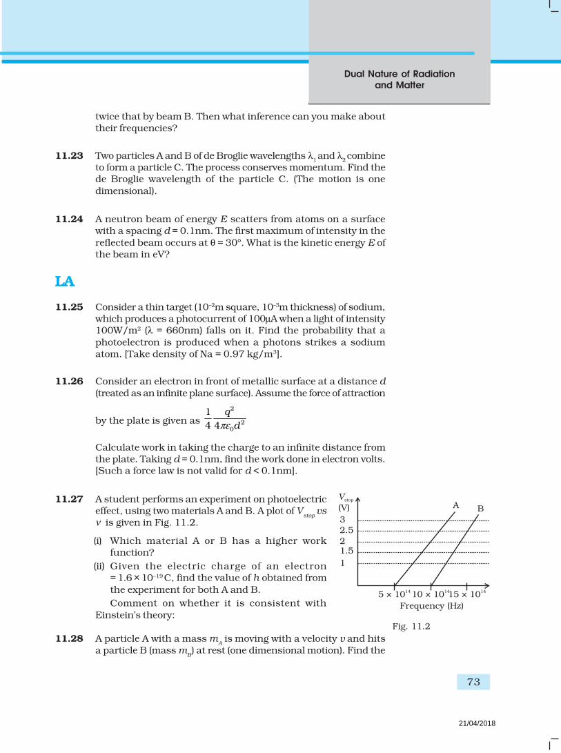
Dual Nature of Radiation
and Matter
73
twice that by beam B. Then what inference can you make abouttheir frequencies?
11.23 Two particles A and B of de Broglie wavelengths λ1 and λ
2 combine
to form a particle C. The process conserves momentum. Find thede Broglie wavelength of the particle C. (The motion is one
dimensional).
11.24 A neutron beam of energy E scatters from atoms on a surfacewith a spacing d = 0.1nm. The first maximum of intensity in the
reflected beam occurs at θ = 30°. What is the kinetic energy E ofthe beam in eV?
LA
11.25 Consider a thin target (10–2m square, 10–3m thickness) of sodium,which produces a photocurrent of 100µA when a light of intensity100W/m2 (λ = 660nm) falls on it. Find the probability that a
photoelectron is produced when a photons strikes a sodiumatom. [Take density of Na = 0.97 kg/m3].
11.26 Consider an electron in front of metallic surface at a distance d
(treated as an infinite plane surface). Assume the force of attraction
by the plate is given as
2
20
1
4 4
q
dπε
Calculate work in taking the charge to an infinite distance fromthe plate. Taking d = 0.1nm, find the work done in electron volts.[Such a force law is not valid for d < 0.1nm].
11.27 A student performs an experiment on photoelectriceffect, using two materials A and B. A plot of V
stop vs
ν is given in Fig. 11.2.
(i) Which material A or B has a higher workfunction?
(ii) Given the electric charge of an electron= 1.6 × 10⁻¹⁹ C, find the value of h obtained from
the experiment for both A and B.
Comment on whether it is consistent with
Einstein’s theory:
11.28 A particle A with a mass mA is moving with a velocity v and hits
a particle B (mass mB) at rest (one dimensional motion). Find the
Fig. 11.2
1
2
3
2.5
1.5
5 × 10¹⁴
10 × 101415 × 10
14
Frequency (Hz)
Vstop
V( ) A B
21/04/2018

Exemplar Problems–Physics
74
change in the de Broglic wavelength of the particle A. Treat thecollision as elastic.
11.29 Consider a 20 W bulb emitting light of wavelength 5000 A°
and
shining on a metal surface kept at a distance 2m. Assume thatthe metal surface has work function of 2 eV and that each atomon the metal surface can be treated as a circular disk of radius
1.5 A°
.
(i) Estimate no. of photons emitted by the bulb per second.
[Assume no other losses]
(ii) Will there be photoelectric emission?
(iii) How much time would be required by the atomc disk to receiveenergy equal to work function (2 eV)?
(iv) How many photons would atomic disk receive within timeduration calculated in (iii) above?
(v) Can you explain how photoelectric effect was observedinstantaneously?
[Hint: Time calculated in part (iii) is from classical considerationand you may further take the target of surface area say 1cm2
and estimate what would happen?]
21/04/2018

Atoms
75
MCQ I
12.1 Taking the Bohr radius as a0 = 53pm, the radius of Li++ ion in its
ground state, on the basis of Bohr’s model, will be about
(a) 53 pm(b) 27 pm(c) 18 pm(d) 13 pm
12.2 The binding energy of a H-atom, considering an electron moving
around a fixed nuclei (proton), is 4
2 2 20
–8
meB
n hε= . (m = electron
mass).
If one decides to work in a frame of reference where the electron isat rest, the proton would be moving arround it. By similararguments, the binding energy would be
4
2 2 20
–8
MeB
n h=
ε (M = proton mass)
Chapter Twelve
ATOMS
21/04/2018

Exemplar Problems–Physics
76
This last expression is not correct because(a) n would not be integral.(b) Bohr-quantisation applies only to electron(c) the frame in which the electron is at rest is not inertial.(d) the motion of the proton would not be in circular orbits, even
approximately.
12.3 The simple Bohr model cannot be directly applied to calculate theenergy levels of an atom with many electrons. This is because
(a) of the electrons not being subject to a central force.(b) of the electrons colliding with each other(c) of screening effects(d) the force between the nucleus and an electron will no longer
be given by Coulomb’s law.
12.4 For the ground state, the electron in the H-atom has an angularmomentum = , according to the simple Bohr model. Angularmomentum is a vector and hence there will be infinitely manyorbits with the vector pointing in all possible directions. Inactuality, this is not true,
(a) because Bohr model gives incorrect values of angularmomentum.
(b) because only one of these would have a minimum energy.(c) angular momentum must be in the direction of spin of electron.(d) because electrons go around only in horizontal orbits.
12.5 O2 molecule consists of two oxygen atoms. In the molecule, nuclearforce between the nuclei of the two atoms
(a) is not important because nuclear forces are short-ranged.(b) is as important as electrostatic force for binding the two atoms.(c) cancels the repulsive electrostatic force between the nuclei.(d) is not important because oxygen nucleus have equal number
of neutrons and protons.
12.6 Two H atoms in the ground state collide inelastically. Themaximum amount by which their combined kinetic energy isreduced is
(a) 10.20 eV(b) 20.40 eV(c) 13.6 eV(d) 27.2 eV
12.7 A set of atoms in an excited state decays.
(a) in general to any of the states with lower energy.(b) into a lower state only when excited by an external electric
field.
21/04/2018

Atoms
77
(c) all together simultaneously into a lower state.(d) to emit photons only when they collide.
MCQ II
12.8 An ionised H-molecule consists of an electron and two protons.The protons are separated by a small distance of the order ofangstrom. In the ground state,
(a) the electron would not move in circular orbits.(b) the energy would be (2)4 times that of a H-atom.(c) the electrons, orbit would go arround the protons.(d) the molecule will soon decay in a proton and a H-atom.
12.9 Consider aiming a beam of free electrons towards free protons.When they scatter, an electron and a proton cannot combine toproduce a H-atom,
(a) because of energy conservation.(b) without simultaneously releasing energy in the from of
radiation.(c) because of momentum conservation.(d) because of angular momentum conservation.
12.10 The Bohr model for the spectra of a H-atom
(a) will not be applicable to hydrogen in the molecular from.(b) will not be applicable as it is for a He-atom.(c) is valid only at room temperature.(d) predicts continuous as well as discrete spectral lines.
12.11 The Balmer series for the H-atom can be observed
(a) if we measure the frequencies of light emitted when an excitedatom falls to the ground state.
(b) if we measure the frequencies of light emitted due totransitions between excited states and the first excited state.
(c) in any transition in a H-atom.(d) as a sequence of frequencies with the higher frequencies
getting closely packed.
12.12 Let 4
2 2 20
1
8n
meE
n hε
−= be the energy of the nth level of H-atom. If all
the H-atoms are in the ground state and radiation of frequency(E2-E1)/h falls on it,
(a) it will not be absorbed at all
21/04/2018

Exemplar Problems–Physics
78
(b) some of atoms will move to the first excited state.(c) all atoms will be excited to the n = 2 state.(d) no atoms will make a transition to the n = 3 state.
12.13 The simple Bohr modle is not applicable to He4 atom because
(a) He4 is an inert gas.(b) He4 has neutrons in the nucleus.(c) He4 has one more electron.(d) electrons are not subject to central forces.
VSA
12.14 The mass of a H-atom is less than the sum of the masses of aproton and electron. Why is this?
12.15 Imagine removing one electron from He4 and He3. Their energylevels, as worked out on the basis of Bohr model will be veryclose. Explain why.
12.16 When an electron falls from a higher energy to a lower energylevel, the difference in the energies appears in the form ofelectromagnetic radiation. Why cannot it be emitted as otherforms of energy?
12.17 Would the Bohr formula for the H-atom remain unchanged if
proton had a charge (+4/3)e and electron a charge ( )3/4 e− ,
where e = 1.6 × 10⁻¹⁹C. Give reasons for your answer.
12.18 Consider two different hydrogen atoms. The electron in each atomis in an excited state. Is it possible for the electrons to havedifferent energies but the same orbital angular momentumaccording to the Bohr model?
SA
12.19 Positronium is just like a H-atom with the proton replaced bythe positively charged anti-particle of the electron (called thepositron which is as massive as the electron). What would be theground state energy of positronium?
12.20 Assume that there is no repulsive force between the electrons inan atom but the force between positive and negative charges isgiven by Coulomb’s law as usual. Under such circumstances,calculate the ground state energy of a He-atom.
21/04/2018

Atoms
79
12.21 Using Bohr model, calculate the electric current created by theelectron when the H-atom is in the ground state.
12.22 Show that the first few frequencies of light that is emitted whenelectrons fall to the nth level from levels higher than n, areapproximate harmonics (i.e. in the ratio 1 : 2: 3...) when n >>1.
12.23 What is the minimum energy that must be given to a H atom in
ground state so that it can emit an Hγ line in Balmer series. If the
angular momentum of the system is conserved, what would be
the angular momentum of such Hγ photon?
LA
12.24 The first four spectral lines in the Lyman serics of a H-atom areλ = 1218 Å, 1028Å, 974.3 Å and 951.4Å. If instead of Hydrogen,we consider Deuterium, calculate the shift in the wavelength ofthese lines.
12.25 Deutrium was discovered in 1932 by Harold Urey by measuringthe small change in wavelength for a particular transition in 1Hand 2H. This is because, the wavelength of transition depend to acertain extent on the nuclear mass. If nuclear motion is takeninto account then the electrons and nucleus revolve around theircommon centre of mass. Such a system is equivalent to a singleparticle with a reduced mass µ, revolving around the nucleus ata distance equal to the electron-nucleus separation. Hereµ = m
eM/(m
e +M) where M is the nuclear mass and m
e is the
electronic mass. Estimate the percentage difference in wavelengthfor the 1st line of the Lyman series in 1H and 2H. (Mass of 1Hnucleus is 1.6725 × 10⁻²⁷ kg, Mass of 2H nucleus is3.3374 × 10–27 kg, Mass of electron = 9.109 × 10⁻³¹ kg.)
12.26 If a proton had a radius R and the charge was uniformlydistributed, calculate using Bohr theory, the ground state energyof a H-atom when (i) R = 0.1Å, and (ii) R = 10 Å.
12.27 In the Auger process an atom makes a transition to a lower statewithout emitting a photon. The excess energy is transferred toan outer electron which may be ejected by the atom. (This iscalled an Auger electron). Assuming the nucleus to be massive,calculate the kinetic energy of an n = 4 Auger electron emittedby Chromium by absorbing the energy from a n = 2 to n = 1transition.
21/04/2018

Exemplar Problems–Physics
80
12.28 The inverse square law in electrostatics is ( )
2
20
| |4 .
e
rπε=F for the
force between an electron and a proton. The 1r
dependence of
| |F can be understood in quantum theory as being due to thefact that the ‘particle’ of light (photon) is massless. If photons hada mass m
p, force would be modified to
( )( )
ee p r
rr r
2
2 20
1| | . –
4λ
λπε
= ×+
F where pm c /λ = andh
2π= .
Estimate the change in the ground state energy of a H-atom if mp
were 10–6 times the mass of an electron.
12.29 The Bohr model for the H-atom relies on the Coulomb’s law ofelectrostatics. Coulomb’s law has not directly been verified forvery short distances of the order of angstroms. SupposingCoulomb’s law between two opposite charge + q
1, –q
2 is modified
to
( )1 2
020
1| | ,
4q q
r Rrπε
= ≥F
1 2 002
0 0
1,
4q q R
r RR r
ε
πε
= ≤
Calculate in such a case, the ground state energy of a H-atom, ifε = 0.1, R
0 = 1Å.
21/04/2018

MCQ I
13.1 Suppose we consider a large number of containers eachcontaining initially 10000 atoms of a radioactive material with a
half life of 1 year. After 1 year,
(a) all the containers will have 5000 atoms of the material.
(b) all the containers will contain the same number of atoms ofthe material but that number will only be approximately 5000.
(c) the containers will in general have different numbers of theatoms of the material but their average will be close to 5000.
(d) none of the containers can have more than 5000 atoms.
13.2 The gravitational force between a H-atom and another particle of
mass m will be given by Newton’s law:
2
.M mF G
r= , where r is in km and
(a) M = mproton
+ m electron
.
(b) M = mproton
+ melectron
2
B
c− (B = 13.6 eV).
Chapter Thirteen
NUCLEI
21/04/2018

Exemplar Problems–Physics
82
(c) M is not related to the mass of the hydrogen atom.
(d) M = mproton
+ m electron
2
| |V
c− (| |V = magnitude of the potential
energy of electron in the H-atom).
13.3 When a nucleus in an atom undergoes a radioactive decay, theelectronic energy levels of the atom
(a) do not change for any type of radioactivity .
(b) change for α and β radioactivity but not for γ-radioactivity.
(c) change for α-radioactivity but not for others.
(d) change for β-radioactivity but not for others.
13.4 Mx and M
y denote the atomic masses of the parent and the daughter
nuclei respectively in a radioactive decay. The Q-value for a β –
decay is Q1 and that for a β + decay is Q
2. If m
e denotes the mass of
an electron, then which of the following statements is correct?
(a) Q1 = (M
x – M
y) c2 and Q
2 = (M
x – M
y – 2m
e)c2
(b) Q1 = (M
x – M
y) c2 and Q
2 = (M
x – M
y )c2
(c) Q1 = (M
x – M
y – 2m
e) c2 and Q
2 = (M
x – M
y +2 m
e)c2
(d) Q1 = (M
x – M
y + 2m
e) c2 and Q
2 = (M
x – M
y +2 m
e)c2
13.5 Tritium is an isotope of hydrogen whose nucleus Triton contains
2 neutrons and 1 proton. Free neutrons decay into ep ν+ + . If
one of the neutrons in Triton decays, it would transform into He3
nucleus. This does not happen. This is because
(a) Triton energy is less than that of a He3 nucleus.
(b) the electron created in the beta decay process cannot remainin the nucleus.
(c) both the neutrons in triton have to decay simultaneouslyresulting in a nucleus with 3 protons, which is not a He3
nucleus.
(d) because free neutrons decay due to external perturbationswhich is absent in a triton nucleus.
13.6. Heavy stable nucle have more neutrons than protons. This is
because of the fact that
(a) neutrons are heavier than protons.
(b) electrostatic force between protons are repulsive.
(c) neutrons decay into protons through beta decay.
(d) nuclear forces between neutrons are weaker than that betweenprotons.
13.7 In a nuclear reactor, moderators slow down the neutrons whichcome out in a fission process. The moderator used have light
nuclei. Heavy nuclei will not serve the purpose because
21/04/2018

Nuclei
83
(a) they will break up.
(b) elastic collision of neutrons with heavy nuclei will not slowthem down.
(c) the net weight of the reactor would be unbearably high.
(d) substances with heavy nuclei do not occur in liquid or gaseous
state at room temperature.
MCQ II
13.8 Fusion processes, like combining two deuterons to form a Henucleus are impossible at ordinary temperatures and pressure.The reasons for this can be traced to the fact:
(a) nuclear forces have short range.
(b) nuclei are positively charged.
(c) the original nuclei must be completely ionized before fusioncan take place.
(d) the original nuclei must first break up before combining witheach other.
13.9 Samples of two radioactive nuclides A and B are taken. λA and λ
B
are the disintegration constants of A and B respectively. In which
of the following cases, the two samples can simultaneously havethe same decay rate at any time?
(a) Initial rate of decay of A is twice the initial rate of decay of B
and λA = λ
B.
(b) Initial rate of decay of A is twice the initial rate of decay of B
and λA > λ
B.
(c) Initial rate of decay of B is twice the initial rate of decay of A
and λA > λ
B.
(d) Initial rate of decay of B is same as the rate of decay of A at
t = 2h and λB < λ
A.
13.10 The variation of decay rate of two radioactive samples A and B
with time is shown in Fig. 13.1.
Which of the following statements are true?
(a) Decay constant of A is greater than that of B, hence A
always decays faster than B.
(b) Decay constant of B is greater than that of A but its
decay rate is always smaller than that of A.
(c) Decay constant of A is greater than that of B but it does
not always decay faster than B.
(d) Decay constant of B is smaller than that of A but still its
decay rate becomes equal to that of A at a later instant.
A
B
t
d N
d t
Fig. 13.1
21/04/2018

Exemplar Problems–Physics
84
VSA
13.11 32He and 3
1He nuclei have the same mass number. Do they have
the same binding energy?
13.12 Draw a graph showing the variation of decay rate with number
of active nuclei.
13.13 Which sample, A or B shown in Fig. 13.2 has shorter mean-life?
13.14 Which one of the following cannot emit radiation and why?
Excited nucleus, excited electron.
13.15 In pair annihilation, an electron and a positron destroy each other
to produce gamma radiation. How is the momentum conserved?
SA
13.16 Why do stable nuclei never have more protons than neutrons?
13.17 Consider a radioactive nucleus A which decays to a stable nucleusC through the following sequence:
A → B → C
Here B is an intermediate nuclei which is also radioactive.
Considering that there are N0 atoms of A initially, plot the graph
showing the variation of number of atoms of A and B versus time.
13.18 A piece of wood from the ruins of an ancient building was found
to have a 14C activity of 12 disintegrations per minute per gramof its carbon content. The 14C activity of the living wood is 16disintegrations per minute per gram. How long ago did the tree,
from which the wooden sample came, die? Given half-life of 14C is5760 years.
13.19 Are the nucleons fundamental particles, or do they consist of
still smaller parts? One way to find out is to probe a nucleon justas Rutherford probed an atom. What should be the kinetic energyof an electron for it to be able to probe a nucleon? Assume the
diameter of a nucleon to be approximately 10–15 m.
13.20 A nuclide 1 is said to be the mirror isobar of nuclide 2 if Z1 =N
2
and Z2 =N
1 . (a) What nuclide is a mirror isobar of 23
11 Na ? (b) Which
nuclide out of the two mirror isobars have greater binding energyand why?
A
B
t
d N
d t
Fig. 13.2
21/04/2018

Nuclei
85
LA
13.21 Sometimes a radioactive nucleus decays into a nucleus which
itself is radioactive. An example is :
half-life half-life38 38 38
=2.48 h =0.62hSulphur Cl Ar (stable)→ → .
Assume that we start with 1000 38S nuclei at time t = 0. Thenumber of 38Cl is of count zero at t = 0 and will again be zero at
t = ∞ . At what value of t, would the number of counts be a
maximum?
13.22 Deuteron is a bound state of a neutron and a proton with abinding energy B = 2.2 MeV. A γ -ray of energy E is aimed at adeuteron nucleus to try to break it into a (neutron + proton)
such that the n and p move in the direction of the incident γ-ray.If E = B, show that this cannot happen. Hence calculate howmuch bigger than B must E be for such a process to happen.
13.23 The deuteron is bound by nuclear forces just as H-atom is madeup of p and e bound by electrostatic forces. If we consider the
force between neutron and proton in deuteron as given in the
form of a Coulomb potential but with an effective charge e ′ :
2
0
1
4
eF
rπε
′=
estimate the value of (e’/e) given that the binding energy of adeuteron is 2.2 MeV.
13.24 Before the neutrino hypothesis, the beta decay process wasthrought to be the transition,
n p e→ +
If this was true, show that if the neutron was at rest, the proton
and electron would emerge with fixed energies and calculatethem.Experimentally, the electron energy was found to have alarge range.
13.25 The activity R of an unknown radioactive nuclide is measuredat hourly intervals. The results found are tabulated as follows:
t (h) 0 1 2 3 4
R (MBq) 100 35.36 12.51 4.42 1.56
21/04/2018

Exemplar Problems–Physics
86
(i) Plot the graph of R versus t and calculate half-life from thegraph.
(ii) Plot the graph of 0
lnR
R
versus t and obtain the value of
half-life from the graph.
13.26 Nuclei with magic no. of proton Z = 2, 8, 20, 28, 50, 52 andmagic no. of neutrons N = 2, 8, 20, 28, 50, 82 and 126 are found
to be very stable. (i) Verify this by calculating the protonseparation energy S
p for 120Sn (Z = 50) and 121Sb = (Z = 51).
The proton separation energy for a nuclide is the minimumenergy required to separate the least tightly bound proton from
a nucleus of that nuclide. It is given by
Sp = (M
Z–1,
N + M
H – M
Z,N) c 2.
Given 119In = 118.9058u, 120Sn = 119.902199u,121Sb = 120.903824u, 1H = 1.0078252u.
(ii) What does the existance of magic number indicate?
21/04/2018

MCQ I
14.1 The conductivity of a semiconductor increases with increase intemperature because
(a) number density of free current carriers increases.
(b) relaxation time increases.
(c) both number density of carriers and relaxation time increase.
(d) number density of current carriers increases, relaxation timedecreases but effect of decrease in relaxation time is much lessthan increase in number density.
14.2 In Fig. 14.1, Vo is the potential barrier across a p-n
junction, when no battery is connected across the junction
(a) 1 and 3 both correspond to forward bias of junction
(b) 3 corresponds to forward bias of junction and 1
corresponds to reverse bias of junction
(c) 1 corresponds to forward bias and 3 corresponds to reverse
bias of junction.
V0
1
2
3
Chapter Fourteen
SEMICONDUCTOR
ELECTRONICSMATERIALS, DEVICESAND SIMPLE CIRCUITS
Fig. 14.1
21/04/2018

Exemplar Problems–Physics
88
(d) 3 and 1 both correspond to reverse bias of junction.
14.3 In Fig. 14.2, assuming the diodes to be ideal,
(a) D1 is forward biased and D
2 is reverse biased and hence current
flows from A to B
(b) D2 is forward biased and D
1 is reverse biased and hence no
current flows from B to A and vice versa.
(c) D1and D
2 are both
forward biased
and hencecurrent flowsfrom A to B.
(d) D1 and D
2 are
both reverse
biased and henceno current flowsfrom A to B and vice versa.
14.4 A 220 V A.C. supply is connected between points A and B(Fig. 14.3). What will be the potential difference V across the
capacitor?
(a) 220V.
(b) 110V.
(c) 0V.
(d) 220 2 V.
14.5 Hole is
(a) an anti-particle of electron.
(b) a vacancy created when an electron leaves a covalent bond.
(c) absence of free electrons.
(d) an artifically created particle.
14.6 The output of the given circuit in Fig. 14.4.
(a) would be zero at all times.
A
A.c.220V
B
VC
~vm sin t
B
AR D1
D2
–10V
Fig. 14.2
Fig. 14.3
Fig. 14.4
(b) would be like a half wave rectifier with positivecycles in output.
(c) would be like a half wave rectifier with negativecycles in output.
(d) would be like that of a full wave rectifier.
21/04/2018
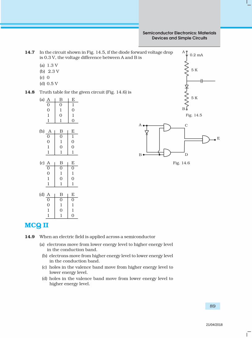
Semiconductor Electronics: Materials
Devices and Simple Circuits
89
14.7 In the circuit shown in Fig. 14.5, if the diode forward voltage dropis 0.3 V, the voltage difference between A and B is
(a) 1.3 V
(b) 2.3 V
(c) 0
(d) 0.5 V
14.8 Truth table for the given circuit (Fig. 14.6) is
(a) A B E0 0 10 1 0
1 0 11 1 0
(b) A B E0 0 10 1 0
1 0 01 1 1
(c) A B E0 0 00 1 1
1 0 01 1 1
(d) A B E0 0 00 1 1
1 0 11 1 0
MCQ II
14.9 When an electric field is applied across a semiconductor
(a) electrons move from lower energy level to higher energy levelin the conduction band.
(b) electrons move from higher energy level to lower energy levelin the conduction band.
(c) holes in the valence band move from higher energy level tolower energy level.
(d) holes in the valence band move from lower energy level tohigher energy level.
A0.2 mA
5 K
5 K
B
E
A
B
C
D
Fig. 14.5
Fig. 14.6
21/04/2018

Exemplar Problems–Physics
90
14.10 Consider an npn transitor with its base-emitter junction forwardbiased and collector base junction reverse biased. Which of the
following statements are true?.
(a) Electrons crossover from emitter to collector.
(b) Holes move from base to collector.
(c) Electrons move from emitter to base.
(d) Electrons from emitter move out of base without going to thecollector.
14.11 Figure 14.7 shows the transfer characteristics of a base biasedCE transistor. Which of the following statements are true?
(a) At Vi = 0.4V, transistor is in active state.
(b) At Vi = 1V , it can be used as an amplifier.
(c) At Vi = 0
..5V, it can be used as a switch turned off.
(d) At Vi = 2.5V, it can be used as a switch turned on.
14.12 In a npn transistor circuit, the collector current is 10mA. If
95 per cent of the electrons emitted reach the collector, which ofthe following statements are true?
(a) The emitter current will be 8 mA.
(b) The emitter current will be 10.53 mA.
(c) The base current will be 0.53 mA.
(d) The base current will be 2 mA.
14.13 In the depletion region of a diode
(a) there are no mobile charges
(b) equal number of holes and electrons exist, making theregion neutral.
(c) recombination of holes and electrons has taken place.
(d) immobile charged ions exist.
14.14 What happens during regulation action of a Zener diode?
(a) The current in and voltage across the Zenor remains fixed.
(b) The current through the series Resistance (Rs) changes.
(c) The Zener resistance is constant.
(d) The resistance offered by the Zener changes.
14.15 To reduce the ripples in a rectifier circuit with capacitor filter
(a) RL should be increased.
(b) input frequency should be decreased.
(c) input frequency should be increased.
(d) capacitors with high capacitance should be used.
Vo
0 0.6V 2V Vi
Fig. 14.7
21/04/2018
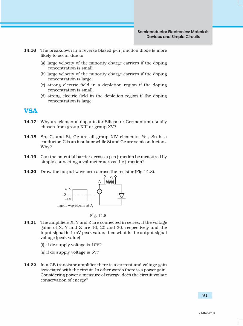
Semiconductor Electronics: Materials
Devices and Simple Circuits
91
14.16 The breakdown in a reverse biased p–n junction diode is morelikely to occur due to
(a) large velocity of the minority charge carriers if the dopingconcentration is small.
(b) large velocity of the minority charge carriers if the dopingconcentration is large.
(c) strong electric field in a depletion region if the dopingconcentration is small.
(d) strong electric field in the depletion region if the dopingconcentration is large.
VSA
14.17 Why are elemental dopants for Silicon or Germanium usuallychosen from group XIII or group XV?
14.18 Sn, C, and Si, Ge are all group XIV elements. Yet, Sn is aconductor, C is an insulator while Si and Ge are semiconductors.Why?
14.19 Can the potential barrier across a p-n junction be measured bysimply connecting a voltmeter across the junction?
14.20 Draw the output waveform across the resistor (Fig.14.8).
–1V
0
+1V
A
V0
Fig. 14.8
14.21 The amplifiers X, Y and Z are connected in series. If the voltage
gains of X, Y and Z are 10, 20 and 30, respectively and theinput signal is 1 mV peak value, then what is the output signalvoltage (peak value)
(i) if dc supply voltage is 10V?
(ii) if dc supply voltage is 5V?
14.22 In a CE transistor amplifier there is a current and voltage gainassociated with the circuit. In other words there is a power gain.Considering power a measure of energy, does the circuit voilate
conservation of energy?
Input waveform at A
21/04/2018

Exemplar Problems–Physics
92
S.A
14.23
R1
R2v
A
Fig. 14.9
Fig. 14.10
P
I
( A)
(volt)V
P
I
Q
V
(i) Name the type of a diode whose characteristics are shown inFig. 14.9 (A) and Fig. 14.9(B).
(ii) What does the point P in Fig. (A) represent?
(iii) What does the points P and Q in Fig. (B) represent?
14.24 Three photo diodes D1, D2 and D3 are made of semiconductorshaving band gaps of 2.5eV, 2eV and 3eV, respectively. Which
ones will be able to detect light of wavelength 60000
A ?
14.25 If the resistance R1 is increased (Fig.14.10), how will the readings
of the ammeter and voltmeter change?
14.26 Two car garages have a common gate which needs to open
automatically when a car enters either of the garages or carsenter both. Devise a circuit that resembles this situation usingdiodes for this situation.
14.27 How would you set up a circuit to obtain NOT gate using atransistor?
14.28 Explain why elemental semiconductor cannot be used to makevisible LEDs.
(a) (b)
21/04/2018

Semiconductor Electronics: Materials
Devices and Simple Circuits
93
Fig. 14.11
D1
D2
A
B
V0
+ 5V14.29 Write the truth table for the circuit shown in Fig.14.11.
Name the gate that the circuit resembles.
14.30 A Zener of power rating 1 W is to be used as a voltageregulator. If zener has a breakdown of 5V and it has toregulate voltage which fluctuated between 3V and 7V, what
should be the value of Rs for safe operation (Fig.14.12)?
LA
14.31 If each diode in Fig. 14.13 has a forward bias resistance of
25Ω and infinite resistance in reverse bias, what will be thevalues of the current I
1, I
2, I
3 and I
4?
14.32 In the circuit shown in Fig.14.14, when the input voltage of the
base resistance is 10V, Vbe
is zero and Vce is also zero. Find the
values of Ib, I
c and β.
14.33 Draw the output signals C1 and C
2 in the given combination of
gates (Fig. 14.15).
A
B
0
0
1
1
2
2
3
3
4
4
5
5
t (s)
t (s)
A
B
C1
A
BC2
Fig. 14.15
A
I3
I2
5VG
I1
E
C
B
D
F
H
25
125
125
125I4
Fig. 14.13
Fig. 14.12
Unregulatedvoltage
Regulatedvoltage
Rs
Rp
400
k
RC
10V
3k
Vi
Fig. 14.14
21/04/2018

Exemplar Problems–Physics
94
14.34 Consider the circuit arrangement shown in Fig 14.16 (a) for study-ing input and output characteristics of npn transistor in CE con-figuration.
VBE
VCE
VBB
BC
E
RC
VCCRB
ICC
Fig. 14.16 (a)
Fig. 14.17
IC
(mA)
IB = 30 A
8V VCE (Volts)
4mAQ
Fig. 14.16 (b)
Select the values of RB and R
C for a transistor whose V
BE = 0.7 V,
so that the transistor is operating at point Q as shown in thecharacteristics shown in Fig. 14.16 (b).
Given that the input impedance of the transistor is very smalland V
CC = V
BB = 16 V, also find the voltage gain and power gain
of circuit making appropriate assumptions.
14.35 Assuming the ideal diode, draw the output waveform for thecircuit given in Fig. 14.17. Explain the waveform.
~
5V
20 sin wt
14.36 Suppose a ‘n’-type wafer is created by doping Si crystal having5 × 1028 atoms/m3 with 1ppm concentration of As. On thesurface 200 ppm Boron is added to create ‘P’ region in this wafer.Considering n
i = 1.5 × 10¹⁶ m–3, (i) Calculate the densities of the
charge carriers in the n & p regions. (ii) Comment which chargecarriers would contribute largely for the reverse saturationcurrent when diode is reverse biased.
21/04/2018

Semiconductor Electronics: Materials
Devices and Simple Circuits
95
14.37 An X-OR gate has following truth table:
A B Y
0 0 0
0 1 1
1 0 1
1 1 0
It is represented by following logic relation
Y =A.B+ A.B
Build this gate using AND, OR and NOT gates.
14.38 Consider a box with three terminals on top of it as shown inFig.14.18 (a):
A
BC
Three components namely, two germanium diodes and oneresistor are connected across these three terminals in somearrangement.A student performs an experiment in which any two of these threeterminals are connected in the circuit shown in Fig. 14.18 (b).
mA
BoxTerminals
VDC
V+
–
The student obtains graphs of current-voltage characteristics forunknown combination of components between the two terminalsconnected in the circuit.
Fig. 14.18 (a)
Fig. 14.18 (b)
21/04/2018

Exemplar Problems–Physics
96
The graphs are
(i) when A is positive and B is negative
I
V
(ii) when A is negative and B is positive
I
V0.7V
(iii) When B is negative and C is positive
I
V0.7V
(iv) When B is positive and C is negative
I
V
10001
slope
Fig. 14.18 (c)
Fig. 14.18 (d)
Fig. 14.18 (e)
Fig. 14.18 (f)
21/04/2018

Semiconductor Electronics: Materials
Devices and Simple Circuits
97
(v) When A is positive and C is negative
I
V
(vi) When A is negative and C is positive
I
V
1.4V
From these graphs of current – voltage charac-teristic shown in Fig. 14.18 (c) to (h), determinethe arrangement of components between A, Band C.
14.39 For the transistor circuit shown in Fig.14.19,evaluate V
E, R
B, R
E given I
C = 1 mA, V
CE = 3V, V
BE
= 0.5 V and VCC
= 12 V,β = 100.
14.40 In the circuit shown in Fig.14.20, find the valueof R
C.
Fig. 14.18 (g)
Fig. 14.19
Fig. 14.18 (h)
Fig. 14.20
ARC100K
12V
20K
C
E
A
VC
R = 7.8KC
RE
V = 12VCC
RB
20K
β = 100
VBE
= 0.5 V
VCE
= 3 V
21/04/2018

98
Exemplar Problems–Physics
MCQ I
15.1 Three waves A, B and C of frequencies 1600 kHz, 5 MHz and
60 MHz, respectively are to be transmitted from one place toanother. Which of the following is the most appropriate mode ofcommunication:
(a) A is transmitted via space wave while B and C are transmittedvia sky wave.
(b) A is transmitted via ground wave, B via sky wave and C viaspace wave.
(c) B and C are transmitted via ground wave while A is transmittedvia sky wave.
(d) B is transmitted via ground wave while A and C are transmittedvia space wave.
15.2 A 100m long antenna is mounted on a 500m tall building. Thecomplex can become a transmission tower for waves with λ
(a) ~ 400 m.
(b) ~ 25 m.
Chapter Fifteen
COMMUNICATION
SYSTEMS
21/04/2018

99
Communication Systems
(c) ~ 150 m.
(d) ~ 2400 m.
15.3 A 1 KW signal is transmitted using a communication channel
which provides attenuation at the rate of – 2dB per km. If thecommunication channel has a total length of 5 km, the power of
the signal received is [gain in dB = 10 log 0
i
P
P
]
(a) 900 W.
(b) 100 W.
(c) 990 W.
(d) 1010 W.
15.4 A speech signal of 3 kHz is used to modulate a carrier signal offrequency 1 MHz, using amplitude modulation. The frequencies
of the side bands will be
(a) 1.003 MHz and 0.997 MHz.
(b) 3001 kHz and 2997 kHz.
(c) 1003 kHz and 1000 kHz.
(d) 1 MHz and 0.997 MHz.
15.5 A message signal of frequency ωm is superposed on a carrier wave
of frequency ωc to get an amplitude modulated wave (AM).
The frequency of the AM wave will be
(a) ωm.
(b) ωC.
(c)2
c mω ω+.
(d)–
2c mω ω
.
15.6 I-V characteristics of four devices are shown in Fig. 15.1
I
V
I
V
I
V
I
V
(i) (ii) (iii) (iv)
Fig. 15.1
21/04/2018

100
Exemplar Problems–Physics
Identify devices that can be used for modulation:
(a) ‘i’ and ‘iii’.
(b) only ‘iii’.
(c) ‘ii’ and some regions of ‘iv’.
(d) All the devices can be used.
15.7 A male voice after modulation-transmission sounds like that of
a female to the receiver. The problem is due to
(a) poor selection of modulation index (selected 0 < m < 1)
(b) poor bandwidth selection of amplifiers.
(c) poor selection of carrier frequency
(d) loss of energy in transmission.
15.8 A basic communication system consists of
(A) transmitter.
(B) information source.
(C) user of information.
(D) channel.
(E) receiver.
Choose the correct sequence in which these are arranged in a
basic communication system:
(a) ABCDE.
(b) BADEC.
(c) BDACE.
(d) BEADC.
15.9 Identify the mathematical expression for amplitude modulatedwave:
(a) Ac sin [ω
c + k
1v
m(t)t + φ ].
(b) Ac sin ω
ct + φ + k
2 v
m(t).
(c) Ac + k
2 v
m(t) sin (ω
ct
+ φ ).
(d) Ac v
m(t) sin (ω
ct
+ φ ).
MCQ II
15.10 An audio signal of 15kHz frequency cannot be transmitted over
long distances without modulation because
(a) the size of the required antenna would be at least 5 kmwhich is not convenient.
21/04/2018

101
Communication Systems
(b) the audio signal can not be transmitted through sky waves.
(c) the size of the required antenna would be at least 20 km,which is not convenient.
(d) effective power transmitted would be very low, if the size ofthe antenna is less than 5 km.
15.11 Audio sine waves of 3 kHz frequency are used to amplitude
modulate a carrier signal of 1.5 MHz. Which of the followingstatements are true?
(a) The side band frequencies are 1506 kHz and 1494 kHz.
(b) The bandwidth required for amplitude modulation is 6kHz.(c) The bandwidth required for amplitude modulation is 3 MHz.(d) The side band frequencies are 1503 kHz and 1497 kHz.
15.12 A TV trasmission tower has a height of 240 m. Signals broadcastfrom this tower will be received by LOS communication at adistance of (assume the radius of earth to be 6.4 × 10⁶ m)
(a) 100 km.(b) 24 km.(c) 55 km.
(d) 50 km.
15.13 The frequency response curve (Fig. 15.2) for the filter circuitused for production of AM wave should be
ωc – ω
m
Gain
Gain
ωc – ω
m ωc + ω
m ω
Gain
ωc – ω
mω
c + ω
m
ω
(i) (ii)
(iii) (iv)
Gain
ωc + ω
mω
Fig. 15.2
21/04/2018

102
Exemplar Problems–Physics
(a) (i) followed by (ii).
(b) (ii) followed by (i).
(c) (iii).
(d) (iv).
15.14 In amplitude modulation, the modulation index m, is kept lessthan or equal to 1 because
(a) m > 1, will result in interference between carrier frequency
and message frequency, resulting into distortion.(b) m > 1 will result in overlapping of both side bands resulting
into loss of information.
(c) m > 1 will result in change in phase between carrier signaland message signal.
(d) m > 1 indicates amplitude of message signal greater than
amplitude of carrier signal resulting into distortion.
VSA
15.15 Which of the following would produce analog signals and which
would produce digital signals?
(i) A vibrating tuning fork.
(ii) Musical sound due to a vibrating sitar string.
(iii) Light pulse.
(iv) Output of NAND gate.
15.16 Would sky waves be suitable for transmission of TV signals of60 MHz frequency?
15.17 Two waves A and B of frequencies 2 MHz and 3 MHz, respectivelyare beamed in the same direction for communication via sky wave.Which one of these is likely to travel longer distance in the
ionosphere before suffering total internal reflection?
15.18 The maximum amplitude of an A.M. wave is found to be 15 Vwhile its minimum amplitude is found to be 3 V. What is the
modulation index?
15.19 Compute the LC product of a tuned amplifier circuit required togenerate a carrier wave of 1 MHz for amplitude modulation.
15.20 Why is a AM signal likely to be more noisy than a FM signalupon transmission through a channel?
21/04/2018

103
Communication Systems
SA
15.21 Figure 15.3 shows a communication system. What is the output
power when input signal is of 1.01mW? (gain in dB = 10 log10
(Po/P
i ).
Fig. 15.3
15.22 A TV transmission tower antenna is at a height of 20 m. Howmuch service area can it cover if the receiving antenna is (i) at
ground level, (ii) at a height of 25 m? Calculate the percentageincrease in area covered in case (ii) relative to case (i).
15.23 If the whole earth is to be connected by LOS communication
using space waves (no restriction of antenna size or tower height),what is the minimum number of antennas required? Calculatethe tower height of these antennas in terms of earths radius?
15.24 The maximum frequency for reflection of sky waves from a certainlayer of the ionosphere is found to be f
max = 9(N
max)1/2, where N
max
is the maximum electron density at that layer of the ionosphere.
On a certain day it is observed that signals of frequencies higherthan 5MHz are not received by reflection from the F
1 layer of the
ionosphere while signals of frequencies higher than 8MHz are
not received by reflection from the F2 layer of the inonosphere.
Estimate the maximum electron densities of the F1 and F
2 layers
on that day.
15.25 On radiating (sending out) an AM modulated signal, the totalradiated power is due to energy carried by ω
c, ω
c – ω
m & ω
c + ω
m.
Suggest ways to minimise cost of radiation without
compromising on information.
Input Output
10dB
5.0 km
2dB km–1
20dB
AmplifierAmplifier
Loss
21/04/2018

104
Exemplar Problems–Physics
LA
15.26 (i) The intensity of a light pulse travelling along a communication
channel decreases exponentially with distance x accordingto the relation I = I
oe–αx, where I
o is the intensity at x = 0 and α
is the attenuation constant.
Show that the intensity reduces by 75 per cent after a distance
of ln 4
α
(ii) Attenuation of a signal can be expressed in decibel (dB)
according to the relation dB =10 log10
o
I
I
. What is the
attenuation in dB/km for an optical fibre in which theintensity falls by 50 per cent over a distance of 50 km?
15.27 A 50 MHz sky wave takes 4.04 ms to reach a receiver viare-transmission from a satellite 600 km above earth’s surface.Assuming re-transmission time by satellite negligible, find
the distance between source and receiver. If communicationbetween the two was to be done by Line of Sight (LOS) method,what should size and placement of receiving and transmitting
antenna be?
15.28 An amplitude modulated wave is as shown in Fig. 15.4. Calculate(i) the percentage modulation, (ii) peak carrier voltage and,
(iii) peak value of information voltage.
Fig. 15.4
100V
20V
V
t
21/04/2018
105
Communication Systems
15.29 (i) Draw the plot of amplitude versus ‘ω’ for an amplitudemodulated wave whose carrier wave (ω
c) is carrying two
modulating signals, ω1 and ω
2 (ω
2 > ω
1). [Hint: Follow
derivation from Eq 15.6 of NCERT Textbook of XII]
(ii) Is the plot symmetrical about ωc? Comment especially about
plot in region ω < ωc.
(iii) Extrapolate and predict the problems one can expect if morewaves are to be modulated.
(iv) Suggest solutions to the above problem. In the process canone understand another advantage of modulation in termsof bandwidth?
15.30 An audio signal is modulated by a carrier wave of 20MHz suchthat the bandwidth required for modulation is 3kHz. Could thiswave be demodulated by a diode detector which has the values
of R and C as(i) R = 1 kΩ, C = 0.01µF.(ii) R = 10 kΩ, C = 0.01µF.
(iii) R = 10 kΩ, C = 0.1µF.
21/04/2018

Exemplar Problems–Physics
198
PHYSICS
CLASS XII
Time: Three Hours Max. Marks: 70
The weightage of the distribution of marks over different dimensions of the question paper
shall be as follows:
A. Weightage to content/subject units
Sl. No. Unit Marks
1. Electrostatics 08
2. Current Electricity 07
3. Magnetic Effect of Current and Magnetism 08
4. Electromagnetic Induction and Alternating Current 08
5. Electromagnetic Waves 03
6. Optics 14
7. Dual Nature of Radiation and Matter 04
8. Atoms and Nuclei 06
9. Semiconductor Electronics 07
10. Communication Systems 05
Total 70
B. Weightage to form of questions
Sl. No. Form of Questions Marks for each No. of Questions Total Marks
Question
1 Long Answer (LA) 5 3 15
2 Short Answer SA (I) 3 09 27
3 Short Answer SA (II) 2 10 20
4 Very Short Answer (VSA) 1 08 08
Total – 30 70
DESIGN OF QUESTION PAPER
21/04/2018
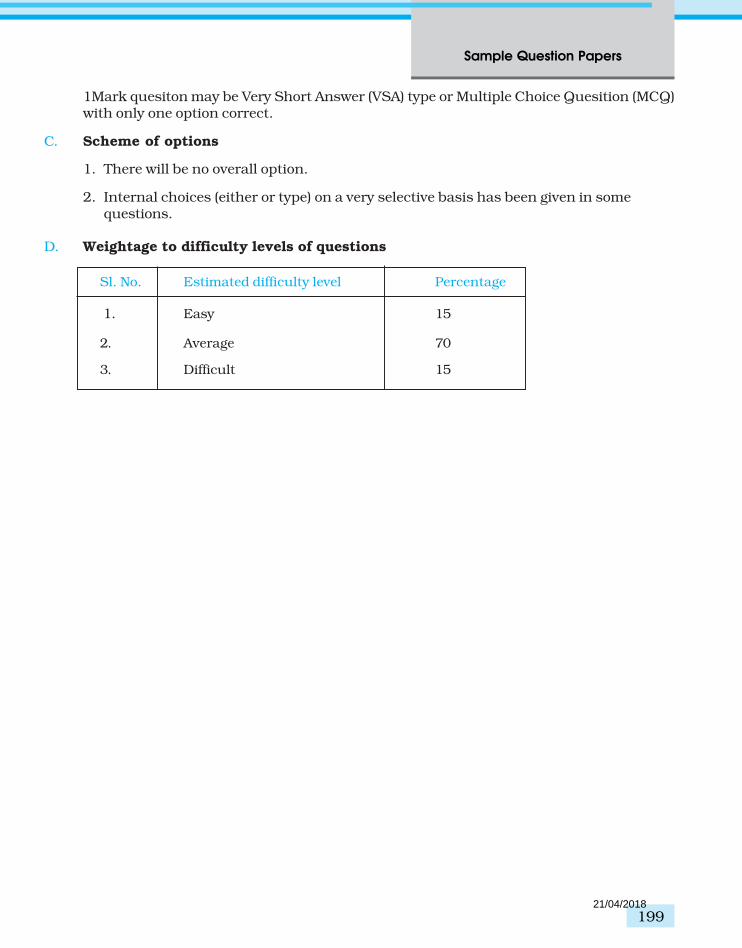
199
Sample Question Papers
1Mark quesiton may be Very Short Answer (VSA) type or Multiple Choice Quesition (MCQ)with only one option correct.
C. Scheme of options
1. There will be no overall option.
2. Internal choices (either or type) on a very selective basis has been given in somequestions.
D. Weightage to difficulty levels of questions
Sl. No. Estimated difficulty level Percentage
1. Easy 15
2. Average 70
3. Difficult 15
21/04/2018

Exemplar Problems–Physics
200
Topic
VSA
(1 m
ark
)SA
II (2
mark
s)
SA
I (3 M
ark
s)
LA
(5 m
ark
s)
Tota
l
IE
lectr
osta
tics
1(1
)4 (2)
3 (1)
—8 (4)
IIC
urr
en
t E
lectr
icit
y1 (1)
—6 (2)
—7 (3)
III
Magn
eti
c E
ffect
of C
urr
en
t1 (1)
2 (1)
—5 (1)
8 (3)
an
d M
agn
eti
sm
IVE
lectr
om
agn
eti
c In
du
cti
on
1(1
)2 (1)
—5 (1)
8 (3)
an
d A
ltern
ati
ng C
urr
en
t
VE
lectr
om
agn
eti
c W
aves
1 (1)
2 (1)
——
3 (2)
VI
Opti
cs
——
9 (3)
5 (1)
14 (4)
VII
Du
al N
atu
re o
f R
adia
tion
—4 (2)
——
4 (2)
an
d M
att
er
VIII
Ato
ms a
nd N
ucle
i1(1
)2 (1)
3 (1)
—6 (3)
IXS
em
icon
du
cto
r E
lectr
on
ics
2 (2)
2 (1)
3 (1)
—7 (4)
XS
yste
ms C
om
mu
nic
ati
on
—
2 (1)
3(1
)—
5 (2)
Tota
l8 (8)
20 (10)
27 (9)
15 (3)
70 (30)
CLA
SS X
IIP
HY
SIC
S
BL
UE -
PR
INT I
21/04/2018

201
Sample Question Papers
SAMPLE PAPER I
XII - PHYSICS
Time : Three Hours Max. Marks : 70
General Instructions
(a) All questions are compulsory.
(b) There are 30 questions in total. Questions 1 to 8 carry one mark each, questions 9 to 18carry two marks each, questions 19 to 27 carry three marks each and questions 28 to 30carry five marks each.
(c) There is no overall choice. However, an internal choice has been provided in all threequestions of five marks each. You have to attempt only one of the given choices in suchquestions.
(d) Use of calculators is not permitted.
(e) You may use the following physical constants wherever necessary :
c = 3 × 10⁸ m s-1
h = 6.6 × 10⁻³⁴ J s
e = 1.6 × 10⁻¹⁹ C
µo = 4π × 10-7 T m A-1
29
20
1 Am9 10
4 Cπε= ×
Boltzmann constant k = 1.38 × 10²³ JK–1
Avogadro’s number NA = 6.023 × 10²³/mole
Mass of neutron mn = 1.6 × 10⁻²⁷ kg
1. Two positive charges q2 and q
3 fixed along the y axis, exert a net electric force in the + x
direction on a charge q1 fixed along the x axis as shown. If a positive charge Q is added at
(x, 0), the force on q1
q2
q1
q3
x
y
( 0)x,
Q
O
q2
q1
q3
x
y
O
21/04/2018
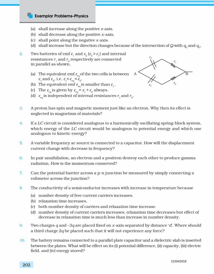
Exemplar Problems–Physics
202
(a) shall increase along the positive x-axis.
(b) shall decrease along the positive x-axis.
(c) shall point along the negative x-axis.
(d) shall increase but the direction changes because of the intersection of Q with q2 and q
3.
2. Two batteries of emf ε1 and ε
2 (ε
2 > ε
1) and internal
resistances r1 and r
2 respectively are connected
in parallel as shown.
(a) The equivalent emf εeq
of the two cells is betweenε
1 and ε
2, i.e. ε
1<
ε
eq <
ε
2.
(b) The equivalent emf εeq
is smaller than ε1 .
(c) The εeq
is given by εeq
= ε1 +
ε
2 always.
(d) εeq
is independent of internal resistances r1 and r
2.
3. A proton has spin and magnetic moment just like an electron. Why then its effect is
neglected in magnetism of materials?
4. If a LC circuit is considered analogous to a harmonically oscillating spring-block system,
which energy of the LC circuit would be analogous to potential energy and which oneanalogous to kinetic energy?
5. A variable frequency ac source is connected to a capacitor. How will the displacement
current change with decrease in frequency?
6. In pair annihilation, an electron and a positron destroy each other to produce gamma
radiation. How is the momentum conserved?
7. Can the potential barrier across a p-n junction be measured by simply connecting a
voltmeter across the junction?
8. The conductivity of a semiconductor increases with increase in temperature because
(a) number density of free current carriers increases.
(b) relaxation time increases.
(c) both number density of carriers and relaxation time increase.
(d) number density of current carriers increases, relaxation time decreases but effect ofdecrease in relaxation time is much less than increase in number density.
9. Two charges q and –3q are placed fixed on x-axis separated by distance ‘d’. Where should
a third charge 2q be placed such that it will not experience any force?
10. The battery remains connected to a parallel plate capacitor and a dielectric slab is inserted
between the plates. What will be effect on its (i) potential difference, (ii) capacity, (iii) electricfield, and (iv) energy stored?
B
r2
r1
A
1
21/04/2018

203
Sample Question Papers
11. Obtain an expression for the magnetic dipole moment of a revolving electron in a Bohr
model.
12. A wire in the form of a tightly wound solenoid is connected to a DC source, and carries a
current. If the coil is stretched so that there are gaps between successive elements of thespiral coil, will the current increase or decrease? Explain.
13. You are given a 2µF parallel plate capacitor. How would you establish an instantaneous
displacement current of 1mA in the space between its plates?
14. There are two sources of light, each emitting with a power of 100 W. One emits X-rays of
wavelength 1nm and the other visible light at 500 nm. Find the ratio of number of photonsof X-rays to the photons of visible light of the given wavelength?
15. A particle is moving three times as fast as an electron. The ratio of the de Broglie wavelength
of the particle to that of the electron is 1.813 × 10⁻⁴. Calculate the particle’s mass andindentify the particle.
16. Consider two different hydrogen atoms. The electron in each atom is in an excited state.
Is it possible for the electrons to have different energies but the same orbital angularmomentum according to the Bohr model?
17. What do the terms ‘depletion region’ and ‘barrier potential’ mean for a p-n junction?
18. If the whole earth is to be connected by LOS communication using space waves (no
restriction of antenna size or tower height), what is the minimum number of antennasrequired? Calculate the tower height of these antennas in terms of earth’s radius?
19. Derive an expression (in vector form) for electric field of a dipole at a point on the equitorial
plane of the dipole. How does the field vary at large distances?
20. What is relaxation time? Derive an expression for resistivity of a wire in terms of member
density of free electrons and relaxation time.
21. First a set of n equal resistors of R each is connected in series to a battery of emf E and
internal resistance R. A current I is observed to flow. Then the n resistors are connected inparallel to the same battery. It is observed that the current becomes10 times. What is ‘n’?
22. An equiconvex lens (of refractive index 1.50) is placed in contact
with a liquid layer on top of a plane mirror as shown. A small needlewith its tip on the principal axis is moved along the axis until itsinverted image is found at the position of the needle. The distanceof the needle from the lens is measured to be 45.0 cm. The liquid isremoved and the experiment is repeated. The new distance ismeasured to be 30.0 cm. What is the refractive index of the liquid?
21/04/2018
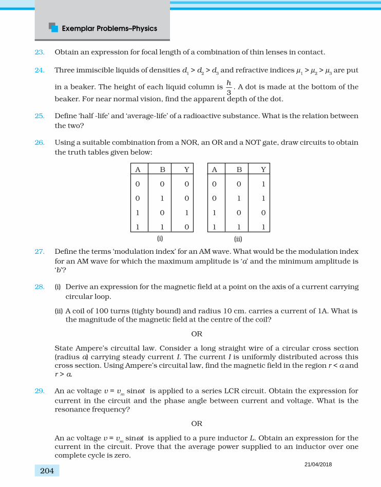
Exemplar Problems–Physics
204
23. Obtain an expression for focal length of a combination of thin lenses in contact.
24. Three immiscible liquids of densities d1 > d
2 > d
3 and refractive indices µ
1 > µ
2 > µ
3 are put
in a beaker. The height of each liquid column is 3
h. A dot is made at the bottom of the
beaker. For near normal vision, find the apparent depth of the dot.
25. Define ‘half -life’ and ‘average-life’ of a radioactive substance. What is the relation between
the two?
26. Using a suitable combination from a NOR, an OR and a NOT gate, draw circuits to obtain
the truth tables given below:
27. Define the terms ‘modulation index’ for an AM wave. What would be the modulation index
for an AM wave for which the maximum amplitude is ‘a’ and the minimum amplitude is‘b’?
28. (i) Derive an expression for the magnetic field at a point on the axis of a current carrying
circular loop.
(ii) A coil of 100 turns (tighty bound) and radius 10 cm. carries a current of 1A. What isthe magnitude of the magnetic field at the centre of the coil?
OR
State Ampere’s circuital law. Consider a long straight wire of a circular cross section(radius a) carrying steady current I. The current I is uniformly distributed across thiscross section. Using Ampere’s circuital law, find the magnetic field in the region r < a andr > a.
29. An ac voltage v = vm sinωt is applied to a series LCR circuit. Obtain the expression for
current in the circuit and the phase angle between current and voltage. What is theresonance frequency?
OR
An ac voltage v = vm sinωt is applied to a pure inductor L. Obtain an expression for the
current in the circuit. Prove that the average power supplied to an inductor over onecomplete cycle is zero.
A B Y
0 0 0
0 1 0
1 0 1
1 1 0
A B Y
0 0 1
0 1 1
1 0 0
1 1 1
(i) (ii)
21/04/2018

205
Sample Question Papers
30. (i) State and explain Huygens Principle. Using it, obtain Snell’s law of refraction.
(ii) When light travels from a rarer to a denser medium, the speed decreases. Does thereduction in speed imply a reduction in the energy carriedby the light wave?
OR
With the help of a labelled ray diagram show the image formation by a compoundmicroscope. Derive an expression for its magnifying power. How can the magnifyingpower be increased?
21/04/2018
Exemplar Problems–Physics
206
SAMPLE PAPER ISOLUTIONS AND MARKING SCHEME
1. (a) (1)
2. (a) (1)
3.2
p
p
e
mµ ≈
and ,
2 2e
e
e h
mµ
π≈ =
(1/2)
e pµ µ>> because mp >> m
e. (1/2)
4. Magnetic energy analogous to kinetic energy and electrical energy analogous to potential
energy. (1/2), (1/2)
5. On decreasing the frequency, reactance 1cX
Cω= will increase which will lead to
decrease in conduction current. In this case iD = i
C; hence displacement current will
decrease. (1/2, 1/2)
6. 2γ photons are produced which move in opposite directions to conserve momentum. (1)
7. No, because the voltmeter must have a resistance very high compared to the junctionresistance, the latter being nearly infinite. (1/2, 1/2)
8. (d) (1)
9. At P: on 2q, Force due to q is to the left and that due to –3q is to the right.
∴ q q
x d x
2 2
2 20 0
2 6
4 4 ( )πε πε=
+(1/2)
∴ (d + x)2 = 3x2
∴ 2x2 – 2dx – d2 = 0
d dx
3
2 2= ± (1/2)
(Negative sign would be between q and –3q and hence is unaceptable.)
d d dx
3(1 3)
2 2 2= + = + to the left of q. (1)
10. When battery remains connected,
(i) potential difference V remains constant. (1/2)
(ii) capacity C increases. (1/2)
P q
– q32q x
d
21/04/2018

207
Sample Question Papers
(iii) electric field will decrease. (1/2)
(iv) energy stored (1/2)CV2 increases as C increases. (1/2)
11. /I e T= (1/2)
2 /T r vπ= (1/2)
2 /2l IA I r evrµ π= = = (1/2)
2l
e
el
mµ = (1/2)
12. The current will increase. As the wires are pulled apart, the flux will leak through the gaps.Lenz’s law demands that induced e.m.f. resist this decrease, which can be done by anincrease in current. (1,1)
13.D
dVi C
dt= (1/2)
–3 –61 10 2 10dV
dt× = ×
3 2110 5 10 V/s
2
dV
dt= × = × (1/2)
Hence, applying a varying potential difference of 5 × 10² V/s would produce a displacementcurrent of the desired value. (1)
14. Total E is constant. (1/2)Let n
1 and n
2 be the number of photons of X-rays and light of visible region:
n1E
1 = n
2E
2(1/2)
1 2
1 2
hc hcn n
λ λ=
1 1
2 2
.n
n
λ
λ= (1/2)
1
2
1
500
n
n= (1/2)
15. de Broglie wavelength of a moving particle, having mass m and velocity v:
λ =h/p=h/mv
Mass, m=h/λv 1/2)
For an electron, mass me = h/λ
e v
e
21/04/2018

Exemplar Problems–Physics
208
Now, we have v/ve = 3 and λ/λ
e = 1.813 × 10⁻⁴ (1/2)
Then, mass of the particle, m= me (λ
e/λ) (v
e/v) (1/2)
m = (9.11 × 10⁻³¹ kg) × (1/3)× (1/1.813 ×10-4)
m =1 × 1.675 × 10-27 kg.
Thus, the particle, with this mass could be a proton or a neutron. (1/2)
16. No, because according to Bohr model, 2
13.6–nE
n= , (1)
and electons having different energies belong to different levels having different valuesof n.
So, their angular momenta will be different, as .2
nhmvr
π= (1)
17. Definition : depletion region (1)
Definition : barrier potential (1)
18. 2 22( )m Td R h= + (1/2)
8RhT = 2(R+h
T)2 ( 2 2 )m Td Rh=
2 24 2T T TRh R h Rh= + +
(R – hT)2 = 0
R = hT
(1/2)
Since space wave frequency is used, λ << hT, hence only tower height is taken to
consideration. In three diamensions, 6 antenna towers of hT = R would do. (1)
19. Derivation (2)
At large distances, E ∝ 1/r3 (1)
20. Definition and Derivation (3)
21. I = E/(R+nR) (1)
10I = E/(R+R/n) (1)
(1+n)/(1+1/n) = 10 = (1+n)/(n+1)n = n, n = 10. (1)
22. µ = 1.5. 45cm is focal length of the combination of convex lens and plano convex liquid
21/04/2018
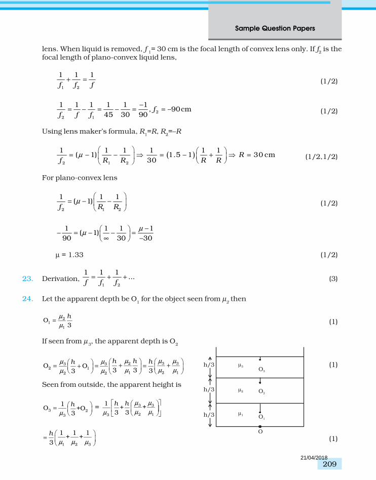
209
Sample Question Papers
lens. When liquid is removed, f 1= 30 cm is the focal length of convex lens only. If f
2 is the
focal length of plano-convex liquid lens,
1 2
1 1 1
f f f+ = (1/2)
2
2 1
1 1 1 1 1 1, 90cm
45 30 90f
f f f
−= − = − = = − (1/2)
Using lens maker’s formula, R1=R, R
2=–R
( )2 1 2
1 1 1 1 1 1( 1) 1.5 1 30 cm
30R
f R R R Rµ
= − − = − + =
(1/2,1/2)
For plano-convex lens
2 1 2
1 1 1( 1)
f R Rµ
= − −
(1/2)
1 1 1 1( 1)
90 30 30
µµ
− − = − − =
∞ −
µ = 1.33 (1/2)
23. Derivation, 1 2
1 1 1...
f f f= + + (3)
24. Let the apparent depth be O1 for the object seen from µ
2 then
21
1
O3
hµ
µ= (1)
If seen from µ3, the apparent depth is O
2
2 3 33 32 1
1 2 12 2
O O3 3 33
h h hh µ µ µµ µ
µ µ µµ µ
+ += = =+ (1)
Seen from outside, the apparent height is
3 23
1O +O
3
h
µ
=
= 3 3
2 13
1++
3 3
h h
µ µ
µ µµ
1 2 3
1 1 1+ +
3
h =
µ µ µ (1)O
3
2
1
h/3
h/3
h/3
O3
O2
O1
21/04/2018

Exemplar Problems–Physics
210
25. Definition and expression: Half Life (1/2,1/2)
Definition and expression: Average life (1/2,1/2)
Relation between the two. (1)
26. Output not symmetric for A, B = (0,1) and (1,0). NOT gate in one input. (1)
(i) has three zero. NOR gate.
Thus (1)
(ii) has three ones. OR gate.
Thus (1)
27. µ = Am/A
c(1)
a = Ac + A
m
b = Ac - A
m(1/2)
Ac = (a + b)/2, A
m = (a–b)/2 (1/2)
µ = (a - b)/(a+b) (1)
28. (i) Derivation (3)
(ii) Since the coil is tighty bound, we may take each circular element to have the sameradius R = 10cm = 0.1m. N=100. The magnitude of the magnetic field is
B = µ0N I/(2 R) = 4π×10-7×10-2× 1/(2 ×10−1) = 2π×10-4 = 6.28 × 10⁻⁴ T. (2)
OR
Statement of Ampere’s law (1)
Derivation of B = µ0 I/2πr, for r > a (2)
Derivation of B = (µ0 I/2πa2) r, for r < a (2)
29. Derivation (4)
Resonance frequency (1)
OR
Derivation (3)
Proof (2)
30. (i) Statement and explanation (1)
4 F
10
2.5V
2
A
BY
21/04/2018

211
Sample Question Papers
Derivation of Snell’s law (3)
(ii) No. Energy carried by a wave depends on the amplitude of the wave, not on thespeed of wave propagation. (1)
OR
(iii) Labelled ray diagram (1)
Derivation 1o e
L Dm
f f
= +
(2)
To Increase magnifying power, the objective and eyepice should have small focallengths. In practice, it is difficult ot make the focal length much smaller than 1 cm.Also large lenses are required to make L large. (1)
21/04/2018

Exe
mp
lar P
rob
lem
s–Ph
ysic
s
212
CLASS XIIPHYSICS
BLUE - PRINT II
Topic VSA (1 mark) SA II (2 marks) SA I (3 Marks) LA (5 marks) Total
I Electrostatics 1(1) 2 (1) — 5 (1) 8 (3)
II Current Electricity — 4 (2) 3 (1) — 7 (3)
III Magnetic Effect of Current 1 (1) 4 (2) 3 (1) — 8 (4)and Magnetism
IV Electromagnetic Induction 1(1) 2 (1) — 5 (1) 8 (3)and Alternating Current
V Electromagnetic Waves 1 (1) 2 (1) — — 3 (2)
VI Optics 2 (2) 4 (2) 3 (1) 5 (1) 14 (6)
VII Dual Nature of Radiation 1 (1) — 3 (1) — 4 (2)and Matter
VIII Atoms and Nuclei — — 6 (2) — 6 (2)
IX Semiconductor Electronics 1 (1) — 6 (2) — 7 (3)
X Communication Systems — 2 (1) 3(1) — 5 (2)
Total 8 (8) 20 (10) 27 (9) 15 (3) 70 (30)
21/04/2018

213
Sample Question Papers
SAMPLE PAPER II
XII - PHYSICS
Time : Three Hours Max. Marks : 70
General Instructions
(a) All questions are compulsory.
(b) There are 30 questions in total. Questions 1 to 8 carry one mark each, questions 9 to 18carry two marks each, questions 19 to 27 carry three marks each and questions 28 to 30carry five marks each.
(c) There is no overall choice. However, an internal choice has been provided in all threequestions of five marks each. You have to attempt only one of the given choices in suchquestions.
(d) Use of calculators is not permitted.
(e) You may use the following physical constants wherever necessary :
c = 3 × 10⁸ms-1
h = 6.6 × 10⁻³⁴Js
e = 1.6 × 10⁻¹⁹ C
µo = 4π × 10-7 T m A-1
29
20
1 Am9 10
4 Cπε= ×
Boltzmann constant k = 1.38 × 10²³ JK-1
Avogadro’s number NA = 6.023 × 10²³/mole
Mass of neutron mn = 1.6 × 10⁻²⁷ kg
1. A capacitor of 4 µ F is connected in a circuit as shown. The internal resistance of the
battery is 0.5 Ω . The amount of charge on the capacitor plates will be
(a) 0
(b) 4 µ C
(c) 16 µ C
(d) 8 µ C
4 F
10
2.5V
2
21/04/2018

Exemplar Problems–Physics
214
2. Two charged particles traverse identical helical paths in a completely opposite sense in a
uniform magnetic field B = B0 k .
(a) They have equal z-components of momenta.
(b) They must have equal charges.
(c) They necessarily represent a particle-antiparticle pair.
(d) The charge to mass ratio satisfy : 1 2
0e e
m m
+ =
.
3. A solenoid is connected to a battery so that a steady current flows through it. If an iron
core is inserted into the solenoid, will the current increase or decrease? Explain.
4. Professor C.V Raman surprised his students by suspending freely a tiny light ball in a
transparent vacuum chamber by shining a laser beam on it. Which property of EM waveswas he exhibiting? Give one more example of this property.
5. A passenger in an aeroplane shall
(a) never see a rainbow.
(b) may see a primary and a secondary rainbow as concentric circles.
(c) may see a primary and a secondary rainbow as concentric arcs.
(d) shall never see a secondary rainbow.
6. What is the shape of the wavefront on earth for sunlight?
7. An electron (mass m ) with an initial velocity 0 0ˆ( 0)v v= >v i is in an electric field
0 0ˆ– ( constant 0 )E E= = >E i . It’s de Broglie wavelength at time t is given by
(a) 0
0
0
1eE t
m v
+
λ
(b)0
00
1eE t
mv
+
λ
(c) λ0
(d) λ0t.
8. Explain why elemental semiconductors cannot be used to make
visible LED’s.
9. Five charges, q each are placed at the corners of a regular pentagon
of side ‘a’ as shown.
A
B
CD
E
q
q
q
O
r
a
21/04/2018

215
Sample Question Papers
(i) What will be the electric field at O if the charge from one of the corners (say A) isremoved?
(ii) What will be the electric field at O if the charge q at A is replaced by –q ?
10. Two cells of emf E1 and E
2 have internal resistance r
1 and r
2. Deduce an expression for
equivalent emf of their parallel combination.
11. Draw a circut diagram of a potential divider using a cell and a rheostat. Also mark the
output terminals.
12. If magnetic monopoles existed, how would the Gauss’s law of magnetism be modified?
13. From molecular viewpoint, discuss the temperature dependence of susceptibility for
diamagnetism, paramagnetism and ferromagnetism.
14. A lamp is connected in series with a capacitor. Predict your observations for dc and ac
connections. What happens in each case if the capacitance of the capacitor is reduced?
15. A plane electromagnetic wave of frequency 25 MHz travels in free space along the
x-direction. At a particular point in space and time. E = 6.3 j V/m. What is B at this
point?
16. Define power of a lens. Show that it is inversaly proportional to the focal length of the lens.
17. Two slits are made one millimetre apart and the screen is placed one metre away. What is
the fringe separation when blue-green light of wavelength 500 nm is used?
18. A message signal of frequency 10 kHz and peak voltage of 10 volts is used to modulate a
carrier of frequency 1 MHz and peak voltage of 20 volts. Determine (a) modulation index,and (b) the side bands produced.
19. Draw a curcuit for determining internal resistance of a cell using a potentiometer. Explain
the principle on which this method is based.
20. What do you mean by diamagnetism, paramagnetism and ferromagnetism?
21. For the same objective, find the ratio of the least separation between two points to be
distinguished by a microscope for light of 5000 A
and electrons accelerated through 100Vused as the illuminating substance.
22. Monochromatic light of frequency 6.0 × 10¹⁴ Hz is produced by a laser. The power emitted
is 2.0 × 10⁻³ W. (i) What is the energy of a photon in the light beam? (ii) How manyphotons per second, on an average, are emitted by the source?
21/04/2018

Exemplar Problems–Physics
216
23. State Bohr’s postulate for the ‘permitted orbits’ for electrons in a hydrogen atom. How
this postulate was explained by de Broglie?
24. Explain a beta decay process with an example. Tritium has a half life of 12.5y undergoing
beta decay. What fraction of a sample of pure tritium will remain undecayed after 25 y?
25. What is rectification? With the help of a labelled circuit diagram, explain full wave
rectification using junction diode.
26. Explain briefly, with the help of a circuit diagram, how V-I characteristics of a p-n junction
diode are obtained in (i) forward bias, and (ii) reverse bias. Draw the shapes of the curvesobtained.
27. (i) Draw a block diagram of a communication system.
(ii) What is meant by ‘detection’ of amplitude modulated wave? Describe briefly theessential steps for detection.
28. Derive an expression for potential due to a dipole for distances large compared to the size
of the dipole. How is the potential due to a dipole different from that due to a singlecharge?
OR
Obtain an expression for potential energy of a system of two charges in an external field.
A system consisting of two chargs 7µ C and –2 µC are placed at (-9 cm, 0,0) and(9 cm,0,0) respectively in an external electric field E = A (1/r2) where A = 9 × 10⁵ C m2.Calulate the potential energy of this system.
29. Define ‘self inductance’ of a coil. Obtain an expnession for self inductance of a long solenoid
of cross sectional area A, length l having n turns for unit length. Prove that self inductanceis the analogue of mass in mechanics.
OR
Define ‘mutual inductance’ of to coil. On what factors it depends?
Two concentric circular coils, one of small radius r1 and the other of large radius r
2, such
that r1 << r
2, are placed co-axially with centres coinciding. Obtain the mutual inductance
of the arrangement.
30. Draw a ray diagram to show two refraction of light through a glass prism. Explain with
help of a diagram the dependence of angle of deviation on the angle of incidence. Henceobtain the relation for the angle of minimum deviation in terms of angle of prism andrefractive index of prism.
OR
21/04/2018

217
Sample Question Papers
(i) Using the relation for refraction at a single spherical refracting surface, derive the lensmaker’s formula.
(ii) Double convex lenses are to be manufactured from a glass of refraction index 1.55with both faces of the same radius of curvature. What is the radius of curvature requiredif the focal length is to be 20.0 cm?
21/04/2018

Exemplar Problems–Physics
218
SAMPLE PAPER II
SOLUTIONS AND MARKING SCHEME
01. (a) (1)
02. (d) (1)
03. The current will decrease. As the iron core is inserted in the solenoid, the magnetic fieldincreases and the flux increases. Lent’s law implies that induced e.m.f. should resist thisincrease, which can be achieved by a decrease in current. (1)
04. EM waves exert radiation pressure. Tails of comets are due to solar solarradiation. (1/2, 1/2)
05. (b) (1)
06. Spherical with huge radius as compared to the earth’s radius so that it is almosta plane. (1/2, 1/2)
07. (a) (1)
08. Elemental semiconductor’s band-gap is such that emissions are in infra-redregion. (1/2, 1/2)
09. (i) 20
1along
4
q
rπεOA (1)
(ii) 2
0
1 2along
4
q
rπεOA (1)
10. 1 2I I I= + (1/2)
1 2
1 2
E V E V
r r
− −= +
1 2
1 2 1 2
1 1E EI V
r r r r
= + − +
1 2 2 1 1 2
1 2 1 2
E r E r r rV I
r r r r
+ += −
+ + (1/2)
Comparing with V = Eeq
– Ireq
(1/2)
We get, Eeq
=1 2 2 1
1 2
E r E r
r r
+
+(1/2)
21/04/2018

219
Sample Question Papers
C
E r
R
A
11. Figure shows the desired circuit. The output volage is obtained across. A and C. (1,1)
12. Gauss’s law of magnetism states that the flux of B through any closed surface is always
zero, . 0d = B s (1)
If monopole existed, the right hand side would be equal to monopole (magneticcharge, q
m ) multiplied by µ
o.
. md qµ= B s . (1)
13. Diamagnetism is due to orbital motion of electrons developing magnetic moments oppositeto applied field and hence is not much affected by temperature. (1)
Paramagnetism and ferromagnetism is due to alignments of atomic magnetic moments inthe direction of the applied field. As temperature increases, this aligment is disturbed andhence susceptibilities of both decrease as temperature increases. (1)
14. When a dc source is connected to a capacitor, the capacitor gets charged and after chargingno current flows in the circuit and the lamp will not glow. There will be no change even if Cis reduced. (1)
With ac source, the capacitor offers capacitative reactance (1/ωC) and the current flows inthe circuit. Consquently, the lamp will shine. Reducing C will increase reactance and thelamp will shine less brightly than before. (1)
15. The magnitude of B is
EB
c=
–8
8
6.3V/m2.1 10 T
3 10 m/s= = ×
× (1)
To find the direction, we note that E is along y-direction and the wave propagated alongx-axis. Therefore, B should be in a direction perpendicular to both x-, and y-axes. Using
vector algebra, E ××××× B should be along x-direction. Since, (+ j ) × × × × × (+ k )= i , B is along the
z-direction.
Thus, B= 2.1×××××10–8 k T. (1 )
21/04/2018
Exemplar Problems–Physics
220
16. P = tanδ with diagram (1)
1
/h ff
= =
For small δ, tan δ ∼ δ.
P = 1/f (1)
17. Fringe spacing D
d
λ= (1)
–7
–3
1 5 100.5mm
1 10
× ×=
×
(1)
18. Modulation index = 10/20 = 0.5 (1)
Side bands are at 1010 kHz and 990 kHz. (1)
19. Diagram (1)
E = φ l1
(1/2)
V = φ l2
E/V = l1/l
2(1/2)
E = I (r+R), V= IR
E/V = (r+ R)/R (1/2)
r = R (l1/l
2)-1. (1/2)
20. Diamgnetism (1)
Paramagnetism (1)
Ferromagnetism (1)
21. min
1.22
2sind
λ
β= (1/2)
where β is the angle subtended by the objective at the object.
For light of 5500 A
–7
min
1.22 5.5 10m
2sind
β
× ×= (1)
For electrons accelerated through 100V, the deBroglie wavelength is
21/04/2018

221
Sample Question Papers
–91.2270.13nm 0.13 10 m
100
h
pλ = = = = × (1/2)
–10
min
1.22 1.3 10'
2sind
β
× ×∴ =
(1/2)
min –3
min
0.2 10d
d= ×
' (1/2)
22. (i) Each photon has an energy
E = hv = (6.63 × 10⁻³⁴ J s) (6.0 × 10⁻¹⁴ Hz)
= 3.98 × 10⁻¹⁹ J (1)
(ii) If N is the number of photons emitted by the source per second, the power P transmittedin the beam equals N times the energy per photon E, so that P = NE. Then
PN
E= (1)
3
19
2.0 10 W
3.98 10 J
−
−
×=
× = 5.0 ×
1015 photons per second. (1)
23. Postutate (1)
de Broglie explanation (2)
24. Explanation (1)
Example (1)
Answer : 1/4 of sample (1)
25. Rectification (1/2)
Labelled diagram (1/2)
Explanation (2)
26. Circuit diagram for obtaining characteristic curves (1)
Explanation (1)
21/04/2018

Exemplar Problems–Physics
222
Shape of corves (1)
27. (i) Block diagram of communication system (1)
(ii) Block diagram of a detector (1)
Explanation (1)
28. Derivation (4)
Difference (1)
OR
Derivation (3)
Numerical (2)
29. Definition (1)
Derivation of expression (2)
Proof (2)
OR
Definition of mutual inductance (1)
Dependence on factors (1)
Numerical (3)
30. Labelled diagram (1)
Diagram of δ versus e (1)
Derivation δm = (µ-1)A (3)
OR
(i) Derivation (3)
(ii) µ = 1.55, R1 = R (1/2)
R2 = –R, f = 20 cm.
1 2
1 1 1( 1)
f R Rµ
= − −
(1/2)
1 2
1 1 1 1.10(1.55 1)
20 R R R
= − + =
(1/2)
R=20×1.1 = 22 cm. (1/2)
21/04/2018

Exemplar Problems–Physics
106
ANSWERS
Chapter 1
1.1 (a)
1.2 (a)
1.3 (d)
1.4 (b)
1.5 (c)
1.6 (a)
1.7 (a)
1.8 (c), (d)
1.9 (b), (d)
1.10 (b), (d)
1.11 (c), (d)
1.12 (a), (c).
1.13 (a), (b), (c) and (d).
1.14 Zero.
1.15 (i) 21
–4
Q
Rπ (ii) Q
R224π
1.16 The electric fields bind the atoms to neutral entity. Fields are causedby excess charges. There can be no excess charge on the inter surfaceof an isolated conductor.
1.17 No, the field may be normal. However, the converse is true.
21/04/2018

107
Answers
1.18
Top view Side view
1.19 (i) q
08ε (ii) q
04ε (iii) q
02ε (iv) q
02ε .
1.20 1 Molar mass M of Al has NA = 6.023 × 10²³ atoms.
∴ m = mass of Al paisa coin has A
mN N
M= atoms
Now, ZAl = 13, MAl = 26.9815g
Hence N = 6.02 × 10²³ atoms/mol ×0.75
26.9815g/mol
= 1.6733 × 10²² atoms
∴ q = +ve charge in paisa = N Ze
= (1.67 × 10²²
)(13) (1.60 × 10⁻¹⁹
C)
= 3.48 × 10⁴ C.
q = 34.8 kC of ±ve charge.This is an enormous amount of charge. Thus we see that ordinary neutralmatter contains enormous amount of ± charges.
1.21 (i) 2 42
2391 2 –4 22
0 1
q (3.48 10 C)Nm 1.1 10 N8.99 104 r 10 mC
Fπ ε
× = = = ××
(ii) 2 –2 2
–8 –8 152 12 12 2 2
1 2
r (10 m)10 10 1.1 10 N
r (10 m)F
F FF
= = = = × = ×
(iii) 2 –2 2
–163 12 6 2
1 3
r (10 m)10
r (10 m)F
F= = =
F3 = 10–16 F1 = 1.1 × 10⁷ N.
Conclusion: When separated as point charges these charges exert anenormous force. It is not easy to disturb electrical neutrality.
21/04/2018

Exemplar Problems–Physics
108
1.22 (i) Zero, from symmetry.
(ii) Removing a +ve Cs ion is equivalent to adding singly charged -veCs ion at that location.Net force then is
2
204 r
eF
πε=
where r = distance between the Cl ion and a Cs ion.
2 2 2 –9 2 –9(0.20) +(0.20) +(0.20) ×10 = 3(0.20) ×10=
= 0.346 × 10⁻⁹ m
Hence, 9 –19 2
–11–9 2
(8.99×10 )(1.6 10 )192 10
(0.346×10 )F
×= = ×
= 1.92 × 10⁻⁹ N
Ans 1.92 × 10⁻⁹ N, directed from A to Cl–
1.23 At P: on 2q, Force due to q is to the left and that due to –3q is to theright.
∴
2 2
2 20 0
2 64 4 ( )
q q
x d xπε πε=
+
∴ (d + x)2 = 3x2
∴ 2x2 – 2dx – d2 = 0
d dx
32 2
= ±
(–ve sign would be between q and –3q and hence is unaceptable.)
d d dx
3(1 3)
2 2 2= + = + to the left of q.
1.24 (a) Charges A and C are positive since lines of force emanate from them.
(b) Charge C has the largest magnitude since maximum number offield lines are associated with it.
(c) (i) near A. There is no neutral point between a positive and a negativecharge. A neutral point may exist between two like charges. Fromthe figure we see that a neutral point exists between charges A andC. Also between two like charges the neutral point is closer to thecharge with smaller magnitude. Thus, electric field is zero nearcharge A.
1.25 (a) (i) zero (ii) 20
1 qalongOA
4 rπε
(iii) 2
0
1 2qalongOA
4 rπε
(b) same as (a).
P q
– q32q x
d
21/04/2018

109
Answers
1.26 (a) Let the Universe have a radius R. Assume that the hydrogen atomsare uniformly distributed. The charge on each hydrogen atom ise
H = – (1 + y) e + e = – ye = |ye|
The mass of each hydrogen atom is ~ mp (mass of proton). Expansion
starts if the Coulumb repulsion on a hydrogen atom, at R, is largerthan the gravitational attraction.Let the Electric Field at R be E. Then
4πR2 E = 3
o
4R N ye
3π
ε
(Gauss’s law)
E (R) = o
N ye1 ˆR3 ε
r
Let the gravitational field at R be GR. Then
– 4πR2 GR = 4 πG 3
p4
m R N3
π
R4
G – Gm NR3 ρπ=
R4 ˆ( ) – G 3
m N Rρ= πG R r
Thus the Coulombic force on a hydrogen atom at R is2 2
o
1 Ny e ˆye (R) R3 ε
= rE
The gravitional force on this atom is
( ) 2p R p
4 ˆm – GNm RR3π
=G r
The net force on the atom is
2 22p
o
1 Ny e 4ˆR – GNm R
3 3π
ε
=
F r
The critical value is when
NyR GNm R
C2 2
2p
o
e1 43 3
π
ε=
yc
2p2
o 2
m4 G
eπε =
–11 2 6 –62
9 2 –38
7 10 1.8 10 81 109 10 1.6 10
× × × × ×
× × ×
–3863 10×–19 –18
C 8 10 10y∴ × (b) Because of the net force, the hydrogen atom experiences an
acceleration such that
21/04/2018

Exemplar Problems–Physics
110
2 222
pp 2
o
1 Ny e 4pd RR – GNm Rm =
3 e 3dt
Or, 2
2
2
d R= a R
dt where
2 222p
op
1 Ny e 4p1– GNm=
3 e 3mα
This has a solution at –atR = Ae + Be
As we are seeking an expansion, B = 0.tR Aeα∴ =
tR Ae Rαα α = =.
Thus, the velocity is proportional to the distance from the centre.
1.27 (a) The symmetry of the problem suggests that the electric field is radial.For points r < R, consider a spherical Gaussian surfaces. Then onthe surface
1V
o
dvρε
= rE .dS
2 314 4
r
r
o o
r E k r drπ πε
′ ′=
41 44o
kr
π
ε=
214r
o
E krε
∴ =
( )o
krr21 ˆ
4ε=E r
For points r > R, consider a spherical Gaussian surfaces’ of radiusr,
1.r
o V
d dvρε
= E S
2 344
R
r
o o
kr E r dr
ππ
ε=
o
k R444
=π
ε
r
o
k RE
r
4
24∴ =
ε
( ) ok R rr4 2 ˆ( /4 ) ( / )ε=E r
r
rR
S
S
21/04/2018

111
Answers
(b) The two protons must be on the opposite sides of the centre alonga diameter. Suppose the protons are at a distance r from thecentre.
Now, 34 2R
o
kr dr eπ ′ =
442
4k
R eπ
∴ =
4
2ek
Rπ∴ =
Consider the forces on proton 1. The attractive force due to thecharge distribution is
2 22
4
2ˆ ˆ– – –4 4r
o o
e e re kr
Rε πε= =E r r
The repulsive force is ( )o
e
r
2
2
1 ˆ4 2πε
r
Net force is o o
e e r
r R
2 2 2
2 4
2 ˆ–4 4 4πε πε
r
This is zero such that2 2 2
2 4
216 4o o
e e r
r Rπε πε=
Or, 4 4
4 432 8R R
r = =
1/4(8)R
r =
Thus, the protons must be at a distance 4 8
Rr = from the centre.
1.28 (a) The electric field at γ due to plate α is o
Q
Sˆ–
2εx
The electric field at γ due to plate β is o
q
Sˆ
2εx
Hence, the net electric field is
( )( )
o
Q q
S1
–ˆ–
2ε=E x
(b) During the collision plates &β γ are together and hence must be atone potential. Suppose the charge on β is q
1 and on γ is q
2. Consider
a point O. The electric field here must be zero.
Electric field at 0 due to o
Q
Sˆ–
2α
ε= x
1
r
2
O
r
-Q q Qd
21/04/2018

Exemplar Problems–Physics
112
Electric field at 0 due to o
q
S1 ˆ–
2β
ε= x
Electric Field at 0 due to o
q
S2 ˆ–
2γ
ε= x
( )2 1–0
2 2o o
Q q q
S Sε ε
+∴ + =
1 2–q q Q =
Further, q1 + q
2 = Q + q
1 /2q Q q = +
and q2 = q/2
Thus the charge on β and γ are Q + q/2 and q/2, respectively.
(c) Let the velocity be v at the distance d after the collision. If m is themass of the plate γ, then the gain in K.E. over the round trip mustbe equal to the work done by the electric field.After the collision, the electric field at γ is
( )
o o o
Q qQ q
S S S2
/2 /2ˆ ˆ ˆ–2 2 2ε ε ε
+= + =E x x x
The work done when the plate γ is released till the collision is F1d
where F1 is the force on plate γ.
The work done after the collision till it reaches d is F2d where F
2 is
the force on plate γ .
( )1 1
–2 o
QQ qF E Q
Sε= =
and ( )2
2 2
/2/2
2 o
qF E q
Sε= =
∴ Total work done is
( ) ( ) ( )221 1
– /2– /22 2o o
d dQ qQQ q qS Sε ε =+
( )22(1/2) – /22 o
dmv Q q
Sε =
( )1/2
– /2o
dv Q q
m Sε
∴ =
1.29 (i)2
2 2
[1esuof charge]1dyne =
[1cm]qQ
Fr
= =
Or,1 esu of charge = 1 (dyne)1/2 (cm)Hence, [1 esu of charge] = [F]1/2 L = [MLT–2]1/2 L = M1/2 L3/2 T–1
[1 esu of charge] = M1/2 L3/2 T–1
Thus charge in cgs unit is expressed as fractional powers (1/2) of Mand (3/2) of L.
°o
q1 q2
21/04/2018

113
Answers
(ii) Consider the coloumb force on two charges, each of magnitude1 esu of charge separated by a distance of 1 cm:The force is then 1 dyne = 10–5 N.This situation is equivalent to two charges of magnitude x Cseparated by 10–2m.This gives:
2
–40
1.
4 10x
Fπε
=
which should be 1 dyne = 10–5 N. Thus
x
x
2 –9 2–5
–4 2 20 0
1 1 10 Nm. 10
4 10 4 Cπε πε= =
With 9
1[3] 10
x =×
, this yields
2–9 2 18 2 9
20
1 Nm10 [3] 10 [3] 10
4 Cπε= × × = ×
With [3] → 2.99792458, we get2
92
0
1 Nm8.98755.... 10
4 Cπε= × exactly
1.30 Net force F on q towards the centre O
q q xF
r r r
2 2
2 20 0
22 cos – .
4 4θ
πε πε= =
2
2 2 3/20
–24 ( )
q xF
d xπε=
+
qx kx
d
2
30
–2–
4πε≈ = for x << d.
Thus, the force on the third charge q is proportional to thedisplacement and is towards the centre of the two other charges.Therefore, the motion of the third charge is harmonic with frequency
2
30
24
q k
d m mω
πε= =
and hence mdT
q
1/23 302
2 8π π ε
ω
=
.
1.31 (a) Slight push on q along the axis of the ring gives rise to the situationshown in Fig (b). A and B are two points on the ring at the end of adiameter.
q
x
d– q d – q
21/04/2018

Exemplar Problems–Physics
114
Force on q due to line elements –
2Q
Rπ at A and B is
20
– 1 12. . . . .cos
2 4Q
F qR r
θπ πε
+ =A B
q z
z R z R2 2 2 2 1/2
–Q 1. .
R.4 ( ) ( )π πε=
+ +0
Total force due to ring on q = (FA+B)(πR)
Qq z
z R
–2 2 3/24 ( )0πε
=+
–4
Qq z
πε
0
for z << R
Thus, the force is propotional to negative of displacement. Motionunder such forces is harmonic.(b) From (a)
2
2 3– ...4
d z Qqzm
dt Rπε=
0
or 2
2 3–4
d z Qqz
dt mRπε=
0
That is, 234
mRω
πε=
0
. Hence 42
mRT
πεπ= 0
Chapter 2
2.1 (d)
2.2 (c)
2.3 (c)
2.4 (c)
2.5 (a)
2.6 (c)
2.7 (b), (c), (d)
2.8 (a), (b), (c)
2.9 (b), (c)
2.10 (b), (c)
2.11 (a), (d)
2.12 (a), (b)
2.13 (c) and (d)
(b)
Axis of the ring
Total charge –Q
q
Z
R
–––––––––
–
– – – – – – – – – – – – – – ––
–
–––––––
(a)
21/04/2018
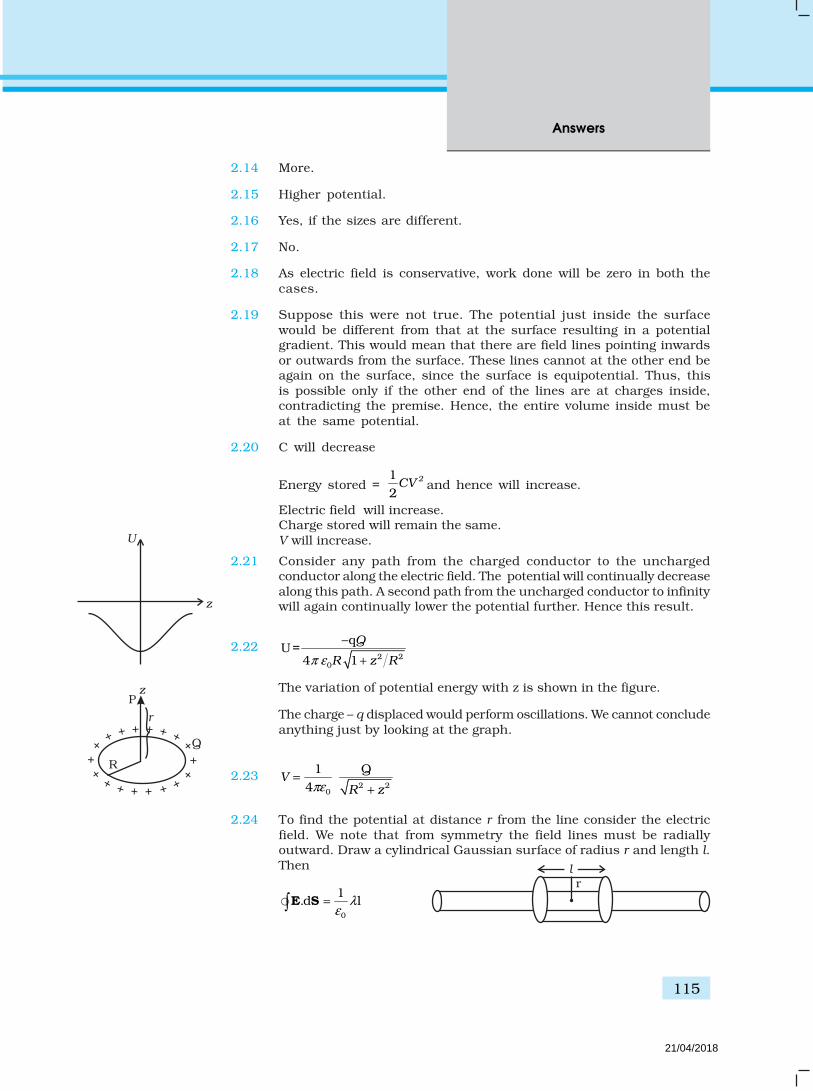
115
Answers
2.14 More.
2.15 Higher potential.
2.16 Yes, if the sizes are different.
2.17 No.
2.18 As electric field is conservative, work done will be zero in both thecases.
2.19 Suppose this were not true. The potential just inside the surfacewould be different from that at the surface resulting in a potentialgradient. This would mean that there are field lines pointing inwardsor outwards from the surface. These lines cannot at the other end beagain on the surface, since the surface is equipotential. Thus, thisis possible only if the other end of the lines are at charges inside,contradicting the premise. Hence, the entire volume inside must beat the same potential.
2.20 C will decrease
Energy stored = 12
2CV and hence will increase.
Electric field will increase.Charge stored will remain the same.V will increase.
2.21 Consider any path from the charged conductor to the unchargedconductor along the electric field. The potential will continually decreasealong this path. A second path from the uncharged conductor to infinitywill again continually lower the potential further. Hence this result.
2.22 Q
R z R2 20
qU=
4 1π ε
−
+
The variation of potential energy with z is shown in the figure.
The charge – q displaced would perform oscillations. We cannot concludeanything just by looking at the graph.
2.232 2
0
1 Q4
VR zπε
=+
2.24 To find the potential at distance r from the line consider the electricfield. We note that from symmetry the field lines must be radiallyoutward. Draw a cylindrical Gaussian surface of radius r and length l.Then
0
1.d lλ
ε= E S
rl
U
z
++++
++
+
+ + + + + +
++
+
++
R
Q
P
r
z
21/04/2018

Exemplar Problems–Physics
116
Or r0
1E 2 rl lπ λ
ε=
r0
E2 r
λ
πε =
Hence, if r0 is the radius,
0
r0
00r
(r) – (r ) .d2
rV V ln
r
λ
πε= − = E l
For a given V,
ln 00
0
2[V(r) – V(r )]
r
r
πε
λ= −
00
Vr V(r)r r 0 02 / 2 /e .eπε λ πε λ− + =
The equipotential surfaces are cylinders of radius
00
V(r)–V(rr r 02 [ )]/e πε λ−
=
2.25 Let the plane be at a distance x from the origin. The potential at thepoint P is
( ) ( )1/2 1/ 22 22 20 0
1 14 4/2 /2
q q
h hx d x dπε πε−
+ ++ − If this is to be zero.
( ) ( )1/2 1/22 22 2
1 1
/2 /2h hx d x d
= + ++ − Or, (x-d/2)2 + h2 = (x+d/2)2 + h2
2 2 2 2/4 /4x dx d x dx d − + = + +
Or, 2dx = 0 x = 0The equation is that of a plane x = 0.
2.26 Let the final voltage be U: If C is the capacitance of the capacitor withoutthe dielectric, then the charge on the capacitor is
Q1 = CU
The capacitor with the dielectric has a capacitance εC. Hence the chargeon the capacitor is
Q U CU 22 ε α= =
The initial charge on the capacitor that was charged isQ0 = CU0
From the conservation of charges,Q0 = Q1 + Q2
Or, CU0 = CU + α CU2
U U u20 0α + − =
UU 01 1 4
2
α
α
− ± +∴ =
2q
-d/2 o x d/2
-q
h
P zy
x
21/04/2018
117
Answers
1 1 6244
− ± +=
1 6254
− ±= volts
As U is positive
625 1 246V
4 4U
−= = =
2.27 When the disc is in touch with the bottom plate, the entire plate is aequipotential. A change q′ is transferred to the disc.
The electric field on the disc is
V
d=
20
Vq r
dε π′∴ = −
The force acting on the disc is
V Vq r
d d
22
0 2ε π′− × =
If the disc is to be lifted, then2
20 2
Vr mg
dε π =
2
20
mgdV
rπε =
2.28 d d u d u dq q q q q q
r r r0
1U= – –
4πε
( ) 9 2–19 2
–15
9×10= 1.6×10 (1 3 ) – (2 3 )(1 3 )– (2 3 )(1 3 )
10
= 2.304 × 10⁻¹³ –141 4– = –7.68×10 J
9 9
= 4.8 × 10⁵ eV = 0.48 MeV = 5.11 × 10⁻⁴ (mnc2)
2.29 Before contact
2.41Q R
2 2
1.4 (2 ) 4 .4 42Q R R Q
After contact :
1 2 1 2 1Q Q Q Q 5Q′′ + = + = ,
2( .4 )=5 R
21/04/2018
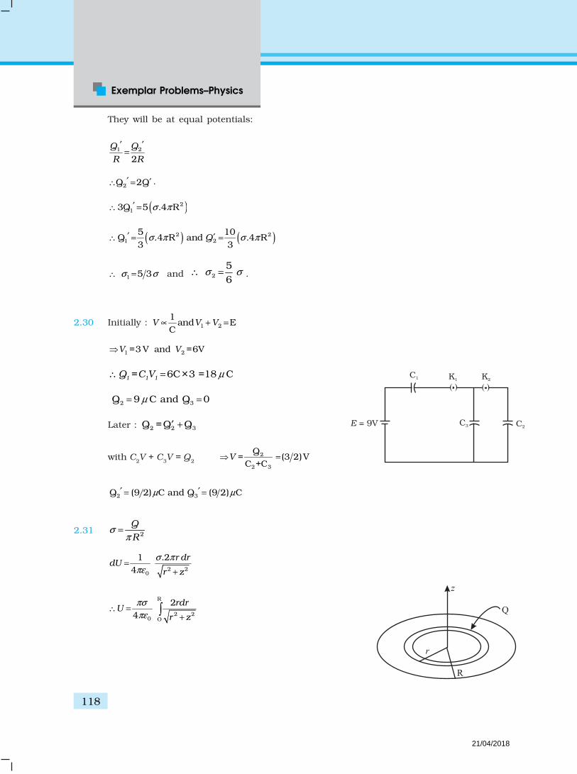
Exemplar Problems–Physics
118
They will be at equal potentials:
1 2
2Q Q
R R
′ ′=
2Q 2Q′ ′∴ = .
( )213Q 5 .4 Rσ π′∴ =
( ) ( )2 21 2
5 10Q .4 R and .4 R
3 3Qσ π σ π′ ′∴ = =
1 5 3σ σ∴ = and 2
56
.
2.30 Initially : V V V1 21
and EC
∝ + =
V V1 2=3 V and =6V
1 1 1Q =C V 6C×3 =18 C
2 3Q 9 C and Q 0
Later : 2 2 3Q =Q Q
with C2V + C3V = Q2 2
2 3
Q= (3 2)V
C +CV =
2 3Q (9 2) C and Q (9 2) Cµ µ′ ′= =
2.31 2
Q
Rσ
π=
2 20
1 .24
r drdU
r z
σ π
πε=
+
R
2 20 O
24
rdrU
r z
πσ
πε∴ =
+
()()
K1 K2
E = 9V
C1
C3 C2
R
z
r
Q
21/04/2018

119
Answers
U
O
R2 2 2 2
O0 0
2 2+z – z
4 4r z R
πσ πσ
πε πε = + =
2 22
0
2Q+ – z
4R z
Rπε =
2.32 ( ) ( )
1 2
2 22 2 2 20
–
q q
x y z d x y z d+ =
+ + + + +
( ) ( )1 2
2 22 2 2 2
–
–
q q
x y z d x y z d∴ =
+ + + + +
Thus, to have total potential zero, q1 and q2 must have oppositesigns. Squaring and simplifying, we get.
( )
( )
21 22 2 2 2
21 2
1(2 ) 0
–1
q qx y z zd d
q q
++ + + + =
This is the equation of a sphere with centre at 2 2
1 12 2
1 1
0,0,–2–
q qd
q q
+
.
Note : if q1 = –q2 Then z = 0, which is a plane through mid-point.
2.33 ( )q q
d x d x
2 2
0
1 – –U
4 – ( – )πε
= +
( )
2
2 20
– 2U
4 –
q d
d xπε=
( )
2
22 20
dU – .2 2.
dx 4 –
q d x
d xπ=
∈
dU0
dx= at x = 0
x = 0 is an equilibrium point.
( )
22 2
2 2 2 32 2 20
2 8d U –2 –( – )dx 4 –
xdqd xd xπ
=
∈
2
00
24
qU
dπε=
q1
z
O
q2 – d
d
21/04/2018

Exemplar Problems–Physics
120
( )2
22 2 22 2 3
0
1–22 – – 8
( – )4dq
d x xd xπ
= ∈
At x = 0
2 22
2 60
U –2 1(2 )
dx 4d dq
ddπ
=
∈ , which is < 0.
Hence, unstable equilibrium.
Chapter 3
3.1 (b)
3.2 (a)
3.3 (c)
3.4 (b)
3.5 (a)
3.6 (a)
3.7 (b), (d)
3.8 (a), (d)
3.9 (a), (b)
3.10 (b), (c)
3.11 (a), (c)
3.12 When an electron approaches a junction, in addition to the uniform
E that it normally faces (which keep the drift velocity dv fixed), there
are accumulation of charges on the surface of wires at the junction.These produce electric field. These fields alter direction of momentum.
3.13 Relaxation time is bound to depend on velocities of electrons andions. Applied electric field affects the velocities of electrons by speedsat the order of 1mm/s, an insignificant effect. Change in T, on theother hand, affects velocities at the order of 102 m/s. This can affectτ significantly.
[ρ = ρ(E,T ) in which E dependence is ignorable for ordinary appliedvoltages.]
3.14 The advantage of null point method in a Wheatstone bridge is that theresistance of galvanometer does not affect the balance point and thereis no need to determine current in resistances and galvanometer andthe internal resistance of a galvanometer. Runknown can be calculated
21/04/2018
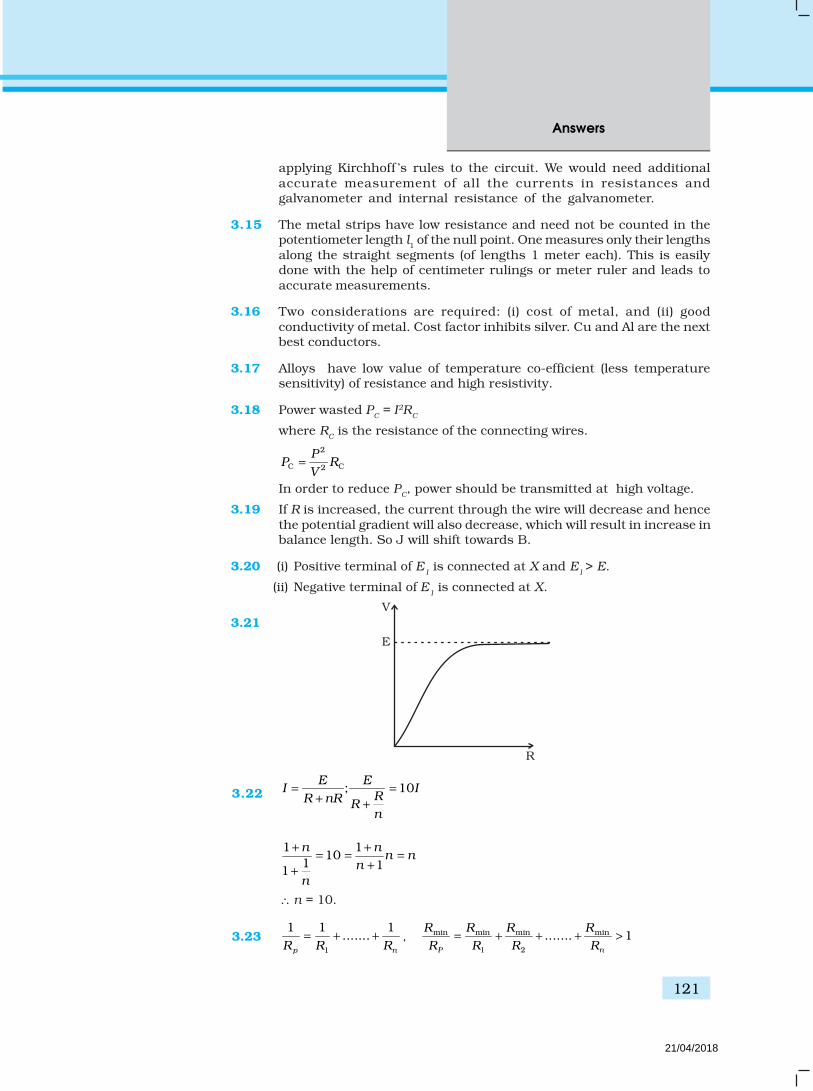
121
Answers
applying Kirchhoff ’s rules to the circuit. We would need additionalaccurate measurement of all the currents in resistances andgalvanometer and internal resistance of the galvanometer.
3.15 The metal strips have low resistance and need not be counted in thepotentiometer length l1 of the null point. One measures only their lengthsalong the straight segments (of lengths 1 meter each). This is easilydone with the help of centimeter rulings or meter ruler and leads toaccurate measurements.
3.16 Two considerations are required: (i) cost of metal, and (ii) goodconductivity of metal. Cost factor inhibits silver. Cu and Al are the nextbest conductors.
3.17 Alloys have low value of temperature co-efficient (less temperaturesensitivity) of resistance and high resistivity.
3.18 Power wasted PC = I2R
C
where RC is the resistance of the connecting wires.
2
C C2
PP R
V=
In order to reduce PC, power should be transmitted at high voltage.
3.19 If R is increased, the current through the wire will decrease and hencethe potential gradient will also decrease, which will result in increase inbalance length. So J will shift towards B.
3.20 (i) Positive terminal of E1 is connected at X and E
1 > E.
(ii) Negative terminal of E1 is connected at X.
3.21
E
R
V
3.22 ; 10E E
I IRR nR Rn
= =+ +
1 110
1 11
n nn n
n
n
+ += = =
++
∴ n = 10.
3.231
1 1 1.......
p nR R R= + + , min min min min
1 2
....... 1P n
R R R R
R R R R= + + + >
21/04/2018

Exemplar Problems–Physics
122
V
Rmin
V
RmaxRmin
V
V
Rmax
(a) (b) (c) (d)
E1 E2
A B
and RS = R1 + ...... + Rn ≥ Rmax.In Fig. (b), Rmin provides an equivalent route as in Fig. (a) for current.But in addition there are (n – 1) routes by the remaining (n – 1) resistors.Current in Fig.(b) > current in Fig. (a). Effective Resistance inFig. (b) < Rmin. Second circuit evidently affords a greater resistance. Youcan use Fig. (c) and (d) and prove Rs > Rmax.
3.246 – 4
0.2A2 8
I = =+
P.D. across E1 = 6 – 0.2 × 2 = 5.6 V
P.D. across E2 = VAB = 4 + 0.2 × 8 = 5.6 V
Point B is at a higher potential than A
3.251 2
E ER
Ir r
+=
+ +
V1 = E – Ir1 =
11 2
2E– 0
RE r
r r=
+ +
or 1
1 2
2ER
rE
r r=
+ +
r r1
1 2
2r1
R=
+ +
r1 + r
2 + R = 2r
1
R = r1 – r2
3.26 A
lR –3 2(10 0.5)
ρ
π=
×
B
lR –3 2 –3 2[(10 ) – (0.5 10 ) ]
ρ
π=
×
A
B
R
R
–3 2 –3 2
–3 2
(10 ) – (0.5 10 )(.5 10 )
×=
× = 3 : 1
21/04/2018

123
Answers
3.27 We can think of reducing entire network to a simple one for anybranch R as shown in Fig.
Then current through R is eff
eff
VI
R R=
+
Dimensionally Veff
= Veff
(V1, V2, ...... Vn) has a dimension of voltage andR
eff = R
eff (R
1, R
2, ....... R
m) has a dimension of resistance.
Therefore if all are increased n-fold
, Rnew neweff eff eff effV nV R n= =
and Rnew = nR.Current thus remains the same.
3.28 Applying Kirchhoff’s junction rule:
I1 = I + I
2
Kirchhoff’s loop rule gives:10 = IR + 10I
1....(i)
2 = 5I2 – RI = 5 (I1 – I) – RI
4 = 10I1 – 10I – 2RI..... (ii)
(i) – (ii) ⇒ 6 = 3RI + 10I or, 2 = I R10
+3
2 = (R+ Reff)I Comparing with Veff
= (R + Reff
)Iand V
eff = 2V
Reff = 103
Ω .
I Veff
Reff
R
I2
I1
R
I2
10V10
2V
R
Veff
I
Reff
3.29 Power consumption = 2units/hour = 2KW = 2000J/s
20009
220P
IV
= = A
Power loss in wire = RI2 J/s
= 2 –8–6
101.7 10 81
10l
IA
ρπ
= × × ××
J/s
4 J/s= 0.2%
Power loss in Al wire = 4 1.6 4 6.4J/s=0.32%Al
Cu
ρ
ρ= × =
21/04/2018

Exemplar Problems–Physics
124
3.30 Let R′ be the resistance of the potentiometer wire.
108
50R
R
′×<
′+10R ′ < 400 + 8R′
2R ′ < 400 or R′ < 200Ω.
108 2 80 40
10R
R RR
′×′ ′> > >
′+
310
4 810
R
R
′×<
′+7.5R′ < 80 + 8R′
R′ > 160 ⇒ 160 < R′ < 200.Any R′ between 160Ω and 200Ω will achieve.Potential drop across 400 cm of wire > 8V.Potential drop across 300 cm of wire < 8V.
φ × 400 > 8V (φ → potential gradient)φ × 300 < 8Vφ > 2V/m
< 2
23
V/m.
3.31 (a) I = 66
= 1 A = nevd A
vd = –4
29 –19 –6
1 110
10 1.6 10 10 1.6= ×
× × × m/s
e dK E m v nAl2
–31 –8 29 –6 –1 –17
1.
21 1
9.1 10 10 10 10 10 2 10 J2 2.56
= ×
= × × × × × × × ×
(b) Ohmic loss = RI2 = 6 × 12 = 6 J/s
All of KE of electrons would be lost in –17
–172 10s 10
6× s
Chapter 4
4.1 (d)
4.2 (a)
4.3 (a)
4.4 (d)
4.5 (a)
21/04/2018

125
Answers
4.6 (d)
4.7 (a), (b)
4.8 (b), (d)
4.9 (b), (c)
4.10 (b), (c), (d)
4.11 (a), (b), (d)
4.12 For a charge particle moving perpendicular to the magnetic field:2mv
qvBR
=
qB v
m Rω∴ = =
–1[ ] [ ] .qB v
Tm R
ω ∴ = = =
4.13 dW= . 0d =F l
. 0dt =F v
. 0 =F v
F must be velocity dependent which implies that angle between F andv is 90°. If v changes (direction) then (directions) F should also changeso that above condition is satisfied.
4.14 Magnetic force is frame dependent. Net acceleraton arising from this ishowever frame independent (non - relativistic physics)for inertial frames.
4.15 Particle will accelerate and decelerate altenatively. So the radius of pathin the Dee’s will remain unchanged.
4.16 At O2, the magnetic field due to I1 is along the y-axis. The second wire isalong the y-axis and hence the force is zero.
4.17 01 ˆ ˆ ˆ( + + )4 2
I
R
µ=B i j k
4.18 No dimensionless quantity –1[ ] [ ]eB
Tm
ω = =
4.19 0 0ˆ ˆ0,0E E B= > =E i B k,
4.20 Force due to d 2l on d 1l is zero.
Force due to d 1l on d 2l is non-zero.
21/04/2018

Exemplar Problems–Physics
126
F1
F2
B
45°
n
Side view
4.21 iG (G + R1) = 2 for 2V range
iG (G + R1+ R2) = 20 for 20V rangeand iG (G + R1+ R2 + R3) = 200 for 200V rangeGives R1 = 1990Ω
R2 = 18 kΩand R3 = 180 kΩ
4.22 F = BIl Sin θ = BIl
o
2I
Bh
µ
π=
2oI
2l
F mgh
µ
π= =
2 –7o
–3
4 10 250 25 12 2 2.5 10 9.8
I lh
mg
µ π
π π
× × × ×= =
× × ×
= 51 × 10–4
h = 0.51 cm
4.23 When the field is off 0τ =Mgl = Wcoil l500 g l = Wcoil lWcoil = 500 × 9.8 NWhen the magnetic field is switched onMgl + mgl = W
coil l + IBL sin 90°l
mgl = BIL l–2
–30.2 4.9 1 1010 kg
9.8BIL
mg
× × ×= = =
= 1 g
4.240
1 1
VF = i lB = lB
R
01 1
2 2 2 2
d V ldBF
Rτ = =
02 2 2
VF i lB lB
R= = 0
2 22 2 4 2
d V ldBF
Rτ = =
Net torque 1 2–τ τ τ=
01
4 2
V AB
Rτ =
4.25 As B is along the x axis, for a circular orbit the momenta of the twoparticles are in the y - z plane. Let p1 and p2 be the momentum of theelectron and positron, respectively. Both of them define a circle ofradius R. They shall define circles of opposite sense. Let p1 make anangleθ with the y axis p2 must make the same angle. The centres ofthe repective circles must be perpendicular to the momenta and at adistance R. Let the center of the electron be at Ce and of the positronat Cp. The coordinates of Ce is
d
B
i1
F1
F2
l
n
Front viewV0
GR1 R2 R3
2V 20V 200V
P Q
h
21/04/2018

127
Answers
Z
y
x
R
1.5 R
Cp
Ce
B
The coordinates of Ce is
(0,– sin , cos )Ce R Rθ θ≡
The coordinates of Cp is
3(0,– sin , R–R cos )
2Cp R θ θ≡
The circles of the two shall not overlap if the distance between the twocenters are greater than 2R.Let d be the distance between Cp and Ce.
Then 2
2 2 3(2RSin ) R – 2Rcos
2d θ θ
= +
22 2 2 2 29
4 Sin – 6 cos 4 cos4
R R R Rθ θ θ= + +
2 2 294 – 6 cos
4R R R θ= +
Since d has to be greater than 2R
d2 > 4R2
2 2 2 294 – 6 cos 4
4R R R Rθ + >
96cos
4θ >
Or, 3
cos .8
θ <
4.26
n = 4 n = 3 n = 2
Area: 23A=
4a A = a2 23 3
4A a=
CurrentI is same for allMagnetic moment m = n I A
2= 3m Ia∴ 3a2I 23 3a I
(Note: m is in a geometric series)
4.27 (a) B (z) points in the same direction on z - axis and hence J (L) is amonotonically increasing function of L.
(b) J(L) + Contribution from large distance on contour 0C Iµ=
asL∴ → ∞
Contribution from large distance 30(asB 1/r )→
0( )J Iµ∞ −
21/04/2018

Exemplar Problems–Physics
128
(c) 2
02 2 3 /22( )z
IRB
z R
µ=
+
20
2 2 3/ 2– – 2( )z
IRB dz dz
z R
µ∞ ∞
∞ ∞=
+ Put z = Rtanθ dz = R sec2 θ d θ
/20
0– – /2cos
2z
IB dz d I
π
π
µθ θ µ
∞
∞∴ = = (d) B(z)square < B (z)circular coil
square circular coil( ) ( )L Lℑ ℑ∴ <
But by using arguments as in (b)
square circular( ) ( )ℑ ℑ∞ = ∞
4.28 iG .G = (i1 – iG) (S1+ S2+ S3) for i1 = 10mA
iG (G + S1) = (i2 –iG) (S2+ S3) for i2 = 100mAand iG (G + S1+S2) = (i3 – iG) (S3) for i3 = 1Agives S1 = 1W, S2 = 0.1W and S3 = 0.01W
4.29 (a) zero
(b) 0
2i
R
µ
π perpendicular to AO towards left.
(c) 0 i
R
µ
π perpendicular to AO towards left.
Chapter 5
5.1 (c)
5.2 (a)
5.3 (c)
5.4 (b)
5.5 (b)
5.6 (a), (d)
5.7 (a), (d)
5.8 (a), (d)
5.9 (a), (c), (d)
5.10 (b), (c), (d)
5.11 2p
p
e
mµ ≈
and ,
2 2e
e
e h
mµ
π≈ =
e pµ µ>> because mp >> me.
–L –LO
21/04/2018
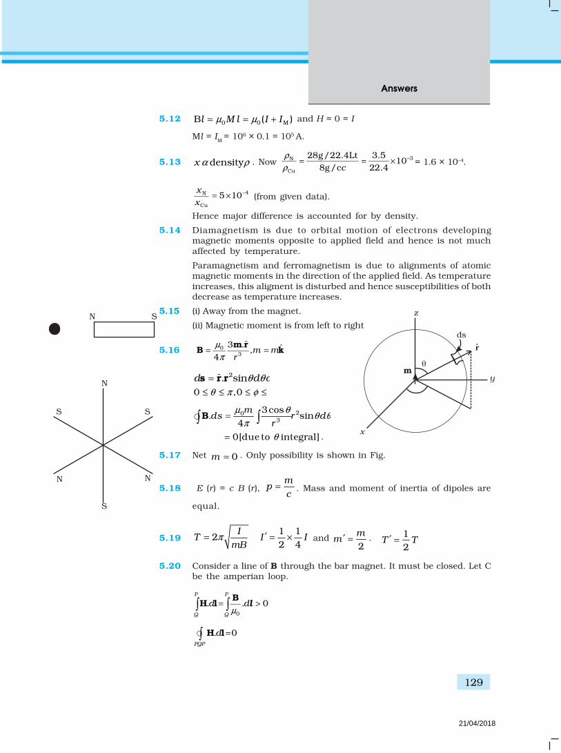
129
Answers
m
ds
z
y
x
r
5.12 0 0 MB ( )l M l I Iµ µ= = + and H = 0 = I
Ml = IM = 106 × 0.1 = 105 A.
5.13 densityx α ρ . Now –3N
Cu
28g/22.4Lt 3.510
8g/c 22.4c
ρ
ρ= = × = 1.6 × 10⁻⁴.
–4N
Cu
5 10x
x= × (from given data).
Hence major difference is accounted for by density.
5.14 Diamagnetism is due to orbital motion of electrons developingmagnetic moments opposite to applied field and hence is not muchaffected by temperature.
Paramagnetism and ferromagnetism is due to alignments of atomicmagnetic moments in the direction of the applied field. As temperatureincreases, this aligment is disturbed and hence susceptibilities of bothdecrease as temperature increases.
5.15 (i) Away from the magnet.
(ii) Magnetic moment is from left to right
5.16 03
ˆ3 . ˆ,4
m mr
µ
π= =
m rB k
2ˆ. sind d dθ θ φ=s r r
0 ,0θ π φ π≤ ≤ ≤ ≤
203
3cos. sin
4m
ds r d dr
µ θθ θ φ
π= B
0[due to integral]θ= .
5.17 Net 0m = . Only possibility is shown in Fig.
5.18 E (r) = c B (r), m
pc
= . Mass and moment of inertia of dipoles are
equal.
5.19 2I
TmB
π=1 12 4
I I′ = × and 2m
m ′ = . 12
T T′ =
5.20 Consider a line of B through the bar magnet. It must be closed. Let Cbe the amperian loop.
0
. . 0P P
Q Q
d dµ
= > B
H l l
. 0PQP
d = H l
S S
NN
N
S
N S
21/04/2018

Exemplar Problems–Physics
130
P Q
C
S N
. 0Q
p
d <H l
P → Q is inside the bar.Hence H is making an obtuse angle with dl.
5.21 (i) Along z axis
03
24 r
µ
π=
mB
0 03 2 2
1 11. 2 ––
4 2 2
R R
a a
dz md m
z R a
µ µ
π π
= = B l
(ii) Along the quarter circle of radius R
( )0 00 3 3
ˆ– . ––sin
4 4m
BR R
µ µθ
π π/ = =
m θθθθ
02. sin
4m
d dR
µθ θ
π=B l
20
20
B.4
mdl
R
π
µ
π=
(iii) Along x-axis
03
–4
m
x
µ
π
=
B
. 0d =B l
(iv) Along the quarter circle of radius a
02
–. sin
4m
d da
µθ θ
π=B l ,
20 0
2 20
– –. –
4 4m m
d sin da a
π
µ µθ θ
π π= = B l
Add . 0C
d = B l
5.22 χ is dimensionless.
χ depends on magnetic moment induced when H is turned on. H
couples to atomic electrons through its charge e. The effect on m is via
current I which involves another factor of ‘e’. The combination 20" "eµ
does not depend on the “charge” Q dimension.
20e m v Rα β γχ µ=
2 22
0 2 2 20 0
1 1 Energy length~ . ~
e ec R
c c R cµ
ε ε=
R
a1
a x xO R
z
21/04/2018

131
Answers
[ χ ] = M0L0T0Q0 = 3 –2
02 –2
ML T LL Q
TM
L T
βα γ
–1, 0, –1α β γ= = =
2 –6 –38–400
–30 –10
10 10~ ~ 10
10 10e
mR
µχ
×=
×.
5.23 (i) 2 2 1/203 (4cos sin )
4m
R
µθ θ
π= +B
22
220
3
3cos 1
4m
R
θµ
π
= +
B, minimum at
2π
θ = .
B is minimum at magnetic equator.
(ii) tan (dip angle) = 2cotV
H
B
B=
at 2π
θ = dip angle vanishes. Magnetic equator is again the
locus.
(iii) Dip angle is ± 45° when 1V
H
B
B=
2 cot θ = 1θ = tan–12 is the locus.
5.24 Refer to the adjacent Fig.
1. P is in S (needle will point both north)
Declination = 0
P is also on magnetic equator.
∴ dip = 0
2. Q is on magnetic equator.
∴ dip = 0
but declination = 11.3°.
5.25 1 2L
nRπ
= 2 4L
na
=
1 1 1IAm n= 2 2 2Im n A=
N
P
Q
GE
ME
11.3°
S
21/04/2018
Exemplar Problems–Physics
132
2L
I RR
ππ
= 2=4 4L L
Ia Iaa
=
2
1 2MR
I = (moment of inertia about an axis through the diameter)
2
2 12Ma
I =
2 11
1
m B
Iω = 2 2
22
m B
Iω =
1 2
1 2
m m
I I=
2 2
34 .2 4
2 12
LIa
LR Ia R
MR Ma
π
π× = =
.
Chapter 6
6.1 (c)
6.2 (b)
6.3 (a)
6.4 (d)
6.5 (a)
6.6 (b)
6.7 (a), (b), (d)
6.8 (a), (b), (c)
6.9 (a), (d)
6.10 (b), (c)
6.11 No part of the wire is moving and so motional e.m.f. is zero. Themagnet is stationary and hence the magnetic field does not changewith time. This means no electromotive force is produced and henceno current will flow in the circuit.
6.12 The current will increase. As the wires are pulled apart the flux willleak through the gaps. Lenz’s law demands that induced e.m.f. resistthis decrease, which can be done by an increase in current.
21/04/2018

133
Answers
6.13 The current will decrease. As the iron core is inserted in the solenoid,the magnetic field increases and the flux increases. Lent’s law impliesthat induced e.m.f. should resist this increase, which can be achievedby a decrease in current.
6.14 No flux was passing through the metal ring initially. When thecurrent is switched on, flux passes through the ring. According toLenz’s law this increase will be resisted and this can happen if thering moves away from the solenoid. One can analyse this in moredetail (Fig 6.5). If the current in the solenoid is as shown, the flux(downward) increases and this will cause a counterclockwise current(as seen form the top in the ring). As the flow of current is in theopposite direction to that in the solenoid, they will repel each otherand the ring will move upward.
6.15 When the current in the solenoid decreases a current flows in thesame direction in the metal ring as in the solenoid. Thus there willbe a downward force. This means the ring will remain on thecardboard. The upward reaction of the cardboard on the ring willincrease.
6.16 For the magnet, eddy currents are produced in the metallic pipe.These currents will oppose the motion of the magnet. Thereforemagnet’s downward acceleration will be less than the accelerationdue to gravity g. On the other hand, an unmagnetised iron bar willnot produce eddy currents and will fall with an acceleration g. Thusthe magnet will take more time.
6.17 Flux through the ring
2( )cosoB a tφ = π ω
2( ) sinB a tε = π ω ω
2( ) sin /I B a t R= π ω ω
Current at
( )2
;2
B at IR
ωπ πω
= = along j
; 0t Iπ
ω= =
( )23;
2
B at I
R
ωπ π= =
ω along ˆ– j .
6.18 One gets the same answer for flux. Flux can be throught of as thenumber of magnetic field lines passing through the surface (we drawdN = B ∆ A lines in an area ∆ A ⊥to B), As lines of of B cannot end orstart in space (they form closed loops) number of lines passing throughsurface S
1 must be the same as the number of lines passing through
the surface S2.
6.19 Motional electric field E along the dotted line CD (⊥ to both v and Band along v × B) = vB
( ,0,0)ax
(0,0,0)
y
k
S1
S2
c
B D B
BC
B
B
P
Q B
Rv
21/04/2018

Exemplar Problems–Physics
134
E.M.F. along PQ = (length PQ)×(Field along PQ)
= coscos
dvB dvB× θ =
θ.
Therefore,
dvBI
R= and is independent of q.
6.20 Maximum rate of change of current is in AB. So maximum back emfwill be obtained between 5s < t <10s.
If u = L 1/5 for 3s, 1/5dI
tdt
= =
(L is a constant)
For 5s < t < 10s 13 3
– – –35 5
u L L e= = =
Thus at t = 7 s, u1 = –3 e.
For 10s < t < 30s
22 120 10 2
Lu L e= = =
For t > 30s u2 = 0
6.21 Mutual inductance –210
5mH2
= =
Flux –3 –35 10 1 5 10= × × = × Wb.
6.22 Let us assume that the parallel wires at are y = 0 and y = d. At t = 0, AB
has x=0 and moves with a velocity ˆvi .
At time t, wire is at x (t) = vt.
Motional e.m.f. = ( ) ( )ˆsin –oB t vdω j
E.m.f due to change in field (along OBAC)
– cos ( )oB t x t dω ω=
Total e.m.f ( ) ( )[ ]– cos sinoB d x vt tω ω ω= +
Along OBAC, Current (clockwise) ( )cos sinoB dx t v t
Rω ω ω= +
Force needed along i ( ) sincos sinoo
B dd B tx t v t
Rωω ω ω= × ×+
( )2 2
sin .cos sinoB dtx t v t
Rωω ω ω= +
6.23 (i) Let the wire be at x = x (t) at time t.
Flux = B (t) l x (t)
( )( ) ( ) ( )– – – .
d dB tE l x B l vt t t
dt dt
φ= = (second term due to motional emf)
y
xB
CA
O
v
21/04/2018

135
Answers
1I E
R=
Force ( )
( ) ( ) ( ) ˆ– –l B dBt
l x B l vt t tR dt
=
i
( )2 2 2 2
2 – –d x l B dB l B dx
m x tdt R dt R dt
=
(ii) 0,dB
dt=
2 2 2
2 0d x l B dx
dt mR dt+ =
2 2
0dv l B
vdt mR
+ =
2 2–A exp l B tv
mR
=
At t = 0, v = uv (t) = u exp (–l2B2t/mR).
(iii)2 2 2 2 2
2 2 2 22
( )exp(–2 / )
B l v t B lI R R u l B t mR
R R= × =
Power lost 2 2
2 2 –( )2 2
01 – e2
2 2
t
l B t/mRB l mR
I R dt uR l B
= =
( )2 2–2 2m m
u v t=
= decrease in kinetic energy.
6.24 Between time t = 0 and 4
tπ
ω= , the rod OP will make contact with the
side BD. Let the length OQ of the contact at some time t such that
04
tπ
ω< < be x. The flux through the area ODQ is
1 1QD×OD= tan
2 2B B l lφ θ= ×
21= B tan where
2l tθ θ ω=
Thus the magnitude of the emf generated is 2 21B sec
2d
l tdt
φε ω ω= =
The current is I =R
ε where R is the resistance of the rod in contact.
A B
C DO
R
P
l
2l
l
Q
x
A B
C D
2l
Ol
P
lx Q
X
B
x t( )
Bl
Y
B
Dx
C
A
R
y
21/04/2018
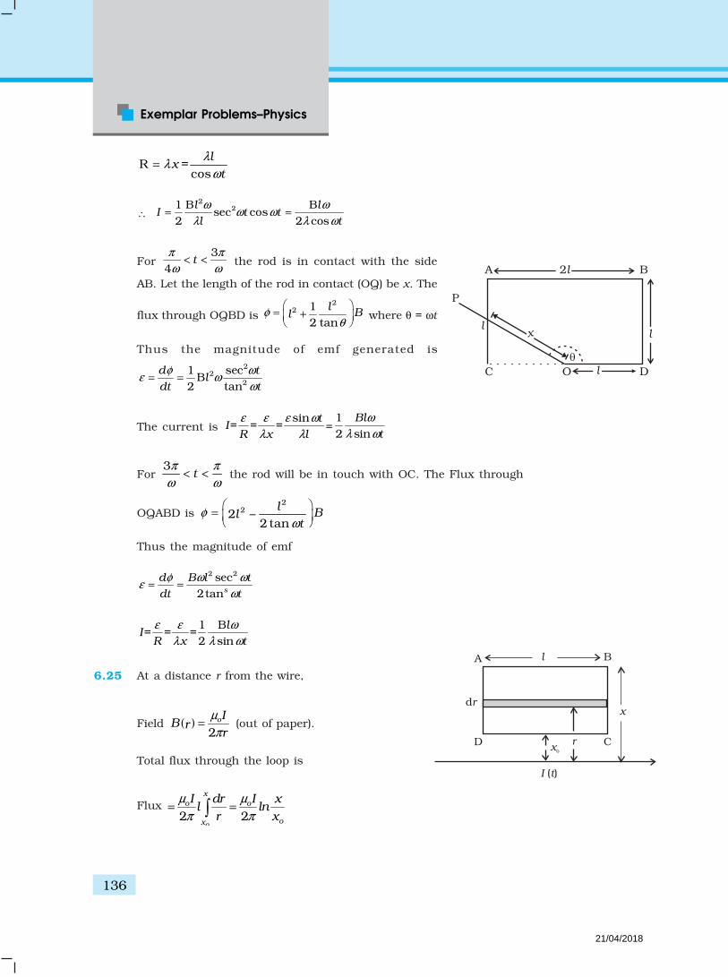
Exemplar Problems–Physics
136
A B
C DO
P
llx
l
2l
R =cos
lx
t
λλ
ω=
∴ 2
21 B Bsec cos
2 2 cosl l
I t tl t
ω ωω ω
λ λ ω= =
For 3
4t
π π
ω ω< < the rod is in contact with the side
AB. Let the length of the rod in contact (OQ) be x. The
flux through OQBD is 2
2 12 tan
lBlφ
θ
= +
where θ = ωt
Thus the magnitude of emf generated is2
22
1 secB
2 tand t
ldt t
φ ωε ω
ω= =
The current is sin
= = =t
IR x l
ε ε ε ω
λ λ=
12 sin
Bl
t
ω
λ ω
For 3
tπ π
ω ω< < the rod will be in touch with OC. The Flux through
OQABD is 2
22 –2 tan
lBl
tφ
ω
=
Thus the magnitude of emf
2 2sec2tans
d B l t
dt t
φ ω ωε
ω= =
1 B= = =
2 sinl
IR x t
ε ε ω
λ λ ω
6.25 At a distance r from the wire,
Field ( )2
oIB rr
µ
π= (out of paper).
Total flux through the loop is
Flux 2 2
o
x
o o
ox
I dr I xl ln
r x
µ µ
π π= =
A
D
B
I t( )
xo
C
l
r
drx
21/04/2018

137
Answers
0
12
odI l xI ln
R dt R R x
ε µ λ
π= = =
6.26 If I (t ) is the current in the loop.
1( )
dI t
R dt
φ=
If Q is the charge that passed in time t,
( )dQ
I tdt
= or 1dQ d
dt R dt
φ=
Integrating ( ) ( ) ( ) ( )1 2 1 21
– –Q t Q t t tR
φ φ=
( ) ( )2
1 1 12
L x
o
x
dxt L I t
x
µφ
π
+′
=′
( )1 21 ln
2oL L x
I tx
µ
π
+=
The magnitute of charge is
[ ]1 2 – 02o
o
L L xIQ ln
x
µ
π
+=
1 1 2ln2oL I L x
x
µ
π
+ =
.
6.272.
2 . .B a
bE E M Ft
ππ = =
∆ where E is the electric field generated around
the ring.
Torque = b × Force = Q E b 2
2B a
Q bb t
π=
π ∆
2
2Ba
Qt
=∆
If ∆L is the change in angular momentum
∆L = Torque × ∆t
2
2Ba
Q=
A
D
B
I (t)
x C
L1
L + x2
21/04/2018

Exemplar Problems–Physics
138
Initial angular momentum = 0
Final angular momentum 2
2
2QBa
mb= ω =
2
22QBa
mbω = .
6.28 ( )2
2
cossin – cos
d x B d dxm mg Bd
Rdt dt
θ = θ × θ
2 22– (cos )
dv B dg sin v
dt mR= θ θ
2 22(cos )
dv B dv g sin
dt mR+ θ = θ
2 22
2 2 2
sinexp – (cos )
cos
g B dv A t
B d mR
mR
θ = + θ θ
(A is a constant to be
determine by initial conditions)
2 22
2 2 2
sin1 – exp – (cos )
cosmgR B d
tB d mR
θ = θ
θ
6.29 If Q (t) is charge on the capacitor (note current flows from A to B)
–vBd Q
IR RC
=
Q dQ vBd
RC dt R + =
∴ [ ]
– /
– /1 –
t RC
t RC
Q vBdC Ae
Q vBdC e
= +
=
(At time t = 0, Q = 0 = A = –vBdc). Differentiating, we get
– /t RCvBdI e
R=
6.30 –dI
L vBd IRdt
+ =
B
BC
B
dv
AX
Y
S
d
B
B B
B
L
B
v
AX
S
B B
21/04/2018

139
Answers
dIL IR vBd
dt+ =
– /2A e RtvBdI
R= +
At t = 0 I = 0 –vBd
AR
=
( )– / .1– Rt LvBd
I eR
=
6.31d
dt
φ= rate of change in flux = (πl2) B
o l
dz
dt= IR.
2ol B
I vR
π λ=
Energy lost/second = I2 R = 2 22 2
ol B v
R
(π λ)
This must come from rate of change in PE = m gdz
dt= mgv
(as kinetic energy is constant for v= constant)
Thus, mgv = 2
02 2l B v
R
(π λ )
Or, v = 2 2 .)o
mgR
( l Bπ λ
6.32 Magnetic field due to a solnoid S, 0B nI= µ
Magnetic flux in smaller coil NBA=φ where 2A b= π
So – –
(NBA)d d
edt dt
φ= =
2 20
(B)– – ( I)
d dN b N b n
dt dt= π = π µ
20
I–
dN b n
dt= π µ
2 2 20 0– ( C) – 2
dNn b mt Nn b mt
dt= πµ + = µ π
20– 2e Nn b mt= µ π
Negative sign signifies opposite nature of induced emf. The magnitudeof emf varies with time as shown in the Fig.
e
t
21/04/2018

Exemplar Problems–Physics
140
Chapter 7
7.1 (b)
7.2 (c)
7.3 (c)
7.4 (b)
7.5 (c)
7.6 (c)
7.7 (a)
7.8 (a), (d)
7.9 (c), (d)
7.10 (a), (b), (d)
7.11 (a), (b), (c)
7.12 (c), (d)
7.13 (a), (d)
7.14 Magnetic energy analogous to kinetic energy and electrical energyanalogous to potential energy.
7.15 At high frequencies, capacitor ≈ short circuit (low reactance) andinductor ≈ open circuit (high reactance). Therefore, the equivalent
circuit 1 3Z R R≈ + as shown in the Fig.
7.16 (a) Yes, if rms voltage in the two circuits are same then at resonance,the rms current in LCR will be same as that in R circuit.
(d) No, because a b,so .R Z I I≤ ≥
7.17 Yes, No.
7.18 Bandwidth corresponds to frequencies at which 1
2m maxI I=
0.7 maxI≈ .
⇒
~
R1 R3
~
R1
R2 R3
21/04/2018

141
Answers
It is shown in the Fig.
∆ω = 1.2 – 0.8 = 0.4 rad/s
7.19 Irms = 1.6A (shown in Fig. by dotted line)
–3
1
0
2
–1
–2
3
T 2T
tI
A()
7.20 From negative to zero to positive; zero at resonant frequency.
7.21 (a) A
(b) Zero
(c) L or C or LC
7.22 An a.c current changes direction with the source frequency andthe attractive force would average to zero. Thus, the a.c amperemust be defined in terms of some property that is independent ofthe direction of current. Joule’s heating effect is such property andhence it is used to define rms value of a.c.
7.23 XL = ωL = 2pfL
= 3.14Ω
2 2Z R L= +
2 2(3.14) (1) 10.86= + =
3.3Ω
tan 3.14L
R
ωφ = =
–1tan (3.14)φ =
72°
72rad.
180π×
Timelag tφ
ω∆ =
72 1s
180 2 50 250π
π
×= =
× ×
.5 1.0 1.5 2.0
0.5
1.0
w
0
(rad/s)
I (A)m
21/04/2018

Exemplar Problems–Physics
142
7.24 PL = 60W, I
L = 0.54A
60110V.
0.54LV = =
The transformer is step-down and have 12
input voltage. Hence
ip = 1
0.27A.2 2I× =
7.25 A capacitor does not allow flow of direct current through it as theresistance across the gap is infinite. When an alternating voltage isapplied across the capacitor plates, the plates are alternately chargedand discharged. The current through the capacitor is a result of thischanging voltage (or charge). Thus, a capacitor will pass more currentthrough it if the voltage is changing at a faster rate, i.e. if the frequencyof supply is higher. This implies that the reactance offered by a capacitoris less with increasing frequency; it is given by 1/ωC.
7.26 An inductor opposes flow of current through it by developing a backemf according to Lenz’s law. The induced voltage has a polarity so asto maintain the current at its present value. If the current is decreasing,the polarity of the induced emf will be so as to increase the currentand vice versa. Since the induced emf is proportional to the rate ofchange of current, it will provide greater reactance to the flow of currentif the rate of change is faster, i.e. if the frequency is higher. The reactanceof an inductor, therefore, is proportional to the frequency, being givenby ωL.
7.27 Power 50,000
252000
2VP Z
Z= = =
Z2 = R2 + (XC – X
L)2 = 625
C L– 3tan –
4X X
Rφ = =
22 2253
625 –164
R RR
= + =
R2 = 400 ⇒ R = 20Ω
XC– X
L = –15Ω
2239 A.
25
2 9=12.6 A.M
VI
Z
I
= =
= ×
21/04/2018
143
Answers
If R, XC, X
L are all doubled, tan φ does not change.
Z is doubled, current is halfed.
Power drawn is halfed.
7.28 (i) Resistance of Cu wires, R
–8
2–4
1.7×10 ×200004
1× 10²
l
Aρ
π
= = = Ω ×
I at 220 V: VI = 106 W ;6
4100.45 10
220I = = × A
RI2 = Power loss
= 4 × (0.45)2 × 10⁸ W
> 106 W
This method cannot be used for transmission
(ii) V′I′ = 106 W = 11000 I′
2110
1.1I ′ = ×
2 4 414 10 =3.3×10 W
1.21RI ′ = × ×
Fraction of power loss 4
6
3.3 10=3.3%
10×
=
7.29 Ri1 = v
m sin ωt 1
sinmv ti
R
ω=
22 2
2 sinm
q dqL v t
C dtω+ =
Let q2 = q
m sin (ωt + φ)
2 sin( ) sin–mm m
qq t v tL
C
ω + = ωω
φ
2
2
1, 0; – 0
1–
mm
vq L
CL
C
= φ = ω >
ω
21/04/2018
Exemplar Problems–Physics
144
2R
2
1, – 0
1–
mvv L
CLw
C
= φ = π ω >
22 cos( )m
dqi q t
dtφ= = ω ω +
i1 and i2 are out of phase. Let us assume 21– 0L
Cω >
1 2sin
cos1
–
m mv t vi i t
R Lc
ω+ = + ω
ωω
Now A sin ωt + B cos ωt = C sin (ωt + φ )
C cos φ = A, C sin φ = B; 2 2C A B= +
Therefore,
12 2 2
1 2 2 2sin( )
[ –1/ ]m mv v
i i tR l C
ω φω ω
+ = ++
–1tan–L C
R
X Xφ =
1/2
2 2
1 11( –1/ )R L CZ
+=
ω ω
7.30 2 21;
2
di qi di dLi Ri vi Li Li
dt c dt dt
+ + = =
= rate of change of energy stored
in an inductor.
Ri2 = joule heating loss
2
rate of change of energy stored in the capacitor.2
q d qi
C dt C
= =
vi = rate at which driving force pours in energy. It goes into (i) ohmicloss and (ii) increase of stored energy.
222
0 0 0
12
T T Td q
dt Ri dt vidtidt C
+ =+
21/04/2018
145
Answers
0
0 ( )T
ve vidt+ + =
0
0T
vidt > if phase difference, a constant is acute.
7.31 (i)2
2 sinm
d q dq qL R v t
dt Cdt+ + = ω
Let q = qm sin (ω t + φ) = – q
m cos (ωt + φ )
i = imsin (ω t + φ ) = qm ω sin (wt + φ )
–1
2 2
–; tan
( – )m m C L
m
C L
v v X Xi
Z RR X Xφ = = =
+
(ii) 2
2 202 2
0
1 1sin ( )
– )2 2m
L
C L
vU Li L t
R X Xφ
= = ω +
+
222
02 2 2
1 1 1cos ( )
( – )2 2m
C
C L
vqU t
R X XC Cφ
= = ω +
+ ω (iii) Left to itself, it is an LC oscillator. The capacitor will go on
discharging and all energy will go to L and back and forth.
Chapter 8
8.1 (c)
8.2 (b)
8.3 (b)
8.4 (d)
8.5 (d)
8.6 (c)
8.7 (c)
8.8 (a), (d)
8.9 (a), (b), (c)
8.10 (b), (d)
21/04/2018

Exemplar Problems–Physics
146
8.11 (a), (c), (d)
8.12 (b), (d)
8.13 (a), (c), (d)
8.14 As electromagnetic waves are plane polarised, so the receivingantenna should be parallel to electric/magnetic part of the wave.
8.15 Frequency of the microwave matches the resonant frequency of watermolecules.
8.16 0–2 sin2C D
dqi i q t
dtπ ν πν= = = .
8.17 On decreasing the frequency, reactance 1cX
Cω= will increase which
will lead to decrease in conduction current. In this case iD = i
C; hence
displacement current will decrease.
8.182 8 –8 2
20–6
0
1 1 3 10 (12 10 )1.71 / .
2 2 1.26 10av
BI c W m
µ
× × ×= = × =
×
8.19
T=2 /
S
tBZ
Ey
8.20 EM waves exert radiation pressure. Tails of comets are due to solarsolar radiation.
8.21 0 0 00
2 14 4 2
D EI dB
r r r dt
µ µ µ φ= = = ε
π π π
20 0 ( )2
dE r
r dt
µ ε= π
π
0 0 .2
r dE
dt
µ ε=
8.22 (a) λ1 → Microwave, λ2 → UV
λ3 → X rays, λ4 → Infrared
(b) λ3 < λ2 < λ4 < λ1
i
21/04/2018

147
Answers
(c) Microwave - RadarUV - LASIK eye surgeryX-ray - Bone fracture identification (bone scanning)Infrared - Optical communication.
8.23 2 20 00
0
1cos ( – )
T
avS c kx t dtT
ε ω×= E B as 20( )c= ε ×S E B
20 0 0
12T
c E BT
ε= ×
02 00 0
0
12
EEascc E
Bcε
== ×
20 0
12
E cε=
20
02E
cµ=
0 0
1cas
µ ε
=
8.24D
dVi C
dt=
–3 –61 10 2 10dV
dt× = ×
3110 5 10 /
2dV
V sdt
= × = ×
Hence, applying a varying potential difference of 5 × 10² V/s wouldproduce a displacement current of desired value.
8.25 Pressure
1( rateof changeof momentum)
Force F p pP F
Area A A t t
∆ ∆= = = = =
∆ ∆
1. ( U energy impartedby wave in time )
Upc t
A tc= ∆ = ∆ = ∆
∆
intensityI U
Ic A t
= =
∆
8.26 Intensity is reduced to one fourth. Tis is beacause the light beamspreads, as it propogates into a spherical region of area 4π r2, but LASERdoes not spread and hence its intensity remains constant.
21/04/2018

Exemplar Problems–Physics
148
8.27 Electric field of an EM wave is an oscillating field and so is the electricforce caused by it on a charged particle. This electric force averagedover an integral number of cycles is zero since its direction changesevery half cycle. Hence, electric field is not responsible for radiationpressure.
8.28ˆ ˆ
2s
oa
λ
πε=
eE j
ˆ2
oi
a
µ
π=B i
ˆ2
o vi
a
µ λ
π=
ˆ1 1 ˆ ˆ( )2 2
s o
o o o
v
a a
λ µ λ
µ µ πε π
= × = ×
jS E B j i
= 2
2 20
– ˆ4
v
a
λ
π εk
8.29 Let the distance between the plates be d. Then the electric field
= sin(2 )oVE t
dπν . The conduction current density is given by the Ohm’s
law = E.
⇒ J c = 1ρ
oV
dsin (2πν t ) = sin(2 )0V
td
πνρ
= c
oJ sin 2πν t
where 00 .c V
Jdρ
=
The displacement current density is given as
Vsin(2 )
d dtd oE
J tt d
ε ε π ν∂ ∂
= =
= o2 Vcos(2 )t
d
ε πνπν
= doJ cos(2 )tνπ , where 0d
02
JV
d
πνε=
21/04/2018

149
Answers
doo
c o oo o
2J . 2 2 80 0.25 4 10J V
V d
d
πνε ρπνερ π ε ν πε ν= = = × × = ×
= 9
10 499 10
ν=
×
8.30 (i) Displacement curing density can be found from the relation
be 0D
d
dtε=
EJ
= ε0 µ
0 I
0 cos
t
∂
∂ (2πν t). ln ˆs
a
k
( )( )202
1 ˆ2 – sin ln2s
I tc a
πν πν =
k
( )2
0ˆ2 sin ln2
aI kt
c s
νπ πν
=
( )02
2 ˆln sin 2a
I ts
ππν
λ =
k
(ii) dDI J sdsdθ=
( )020
22 ln . sin 2
a
s
aI sds t
s
ππ πν
λ=
=
( )2
20
0
12n .sin 2
2
a
s
aI ds l t
s
ππν
λ =
=
( )2 2 22
00
2.sin 2
4
a
s
a s aI d ln t
a s
ππν
λ =
=
( )2 12
00
2– ln .sin 2
4a
I d tπ
ξ ξ πνλ
=
22 2 sin22 0
aI t
ππν
λ
= +
( ∴ The integral has value –1)
21/04/2018

Exemplar Problems–Physics
150
(iii) The displacement current
2
0 02
sin2 2.2
d daI I t = I sin t
ππν πν
λ
=
20
0
dI a
I
π
λ
=
.
8.31 (i)2 3 4 1
1 2 3 4
E.dl E.dl E.dl E.dl E.dl= + + +
2 3 4 1
1 2 3 4
cos 90° cos 0 cos 90° cos 180°E.dl E.dl E.dl E.dl= + + +
0 2 1[ ( – ) – ( – )]h sin kz t sin kz tω ω= E (1)
(ii) For evaluating .B ds let us consider the rectangle
1234 to be made of strips of area ds = h dz each.
2
1
0. cos0 ( – )Z
Z
Bds Bds B sin kz t hdzω= = = B ds
2 1–
[cos( – ) – cos( – )]oB hkz t kz t
kω ω= (2)
(iii)– Bd
dt
φ= E.dl
Using the relations obtained in Equations (1) and (2) andsimplifiying, we get
0 2 1 2 1[ ( – ) – ( – )] [ ( – ) – ( – )]oB hE h sin kz t sin kz t sin kz t sin kz t
kω ω ω ω ω=
0 0E Bk
ω=
0
0
Ec
B=
(iv) For evaluating B.dl , let us consider the loop 1234 in yz plane
as shown in Fig.
h
4 3
21
x
y
Z
E=Ex îE
dl
Edl
E
dl
E dl
B=B0 j
z1 z2
4 3
21
x
y
z
B
ds
dz
dl
B=Byj
z1
h
z2
21/04/2018
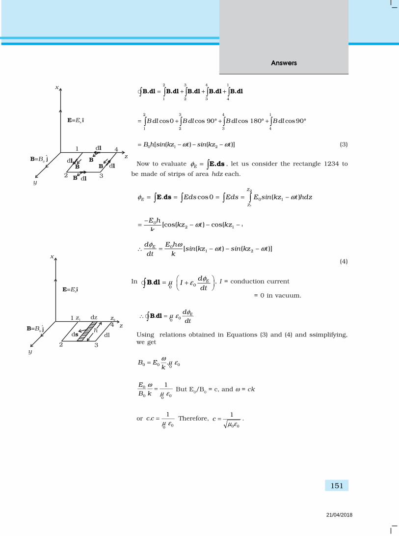
151
Answers
4
32
1
x
y
zB
dl
B=Byj dl
dl
dl
B
B
E=Ex î
B
2 3 4 1
1 2 3 4
= + + + B.dl B.dl B.dl B.dl B.dl
2 3 4 1
1 2 3 4
cos0 cos 90° cos 180° cos90B dl B dl B dl B dl= + + + °
0 1 2[ ( – ) – ( – )]B h sin kz t sin kz tω ω= (3)
Now to evaluate Eφ = E.ds , let us consider the rectangle 1234 to
be made of strips of area hdz each.
2
1
0 1. cos0 ( – )Z
E
Z
Eds Eds E sin kz t hdzφ ω= = = = E ds
2 1–
[cos( – ) – cos( – )]0E hkz t kz t
kω ω=
1 2[ ( – ) – ( – )]E 0d E hsin kz t sin kz t
dt k
φ ωω ω∴ =
(4)
In 00
. EdI
dt
φµ ε
= + B dl , I = conduction current
= 0 in vacuum.
00. Ed
dt
φµ ε∴ = B dl
Using relations obtained in Equations (3) and (4) and ssimplifying,we get
0 0 00.B E
k
ωµ ε=
0
0 00
1E
B k
ω
µ ε= But E0/B0 = c, and ω = ck
or 00
1.c c
µ ε= Therefore,
0 0
1c
µ ε= .
4
32
1
x
y
z
dlB=By j
ds
dz
E=Exî
z1 z2
h
21/04/2018
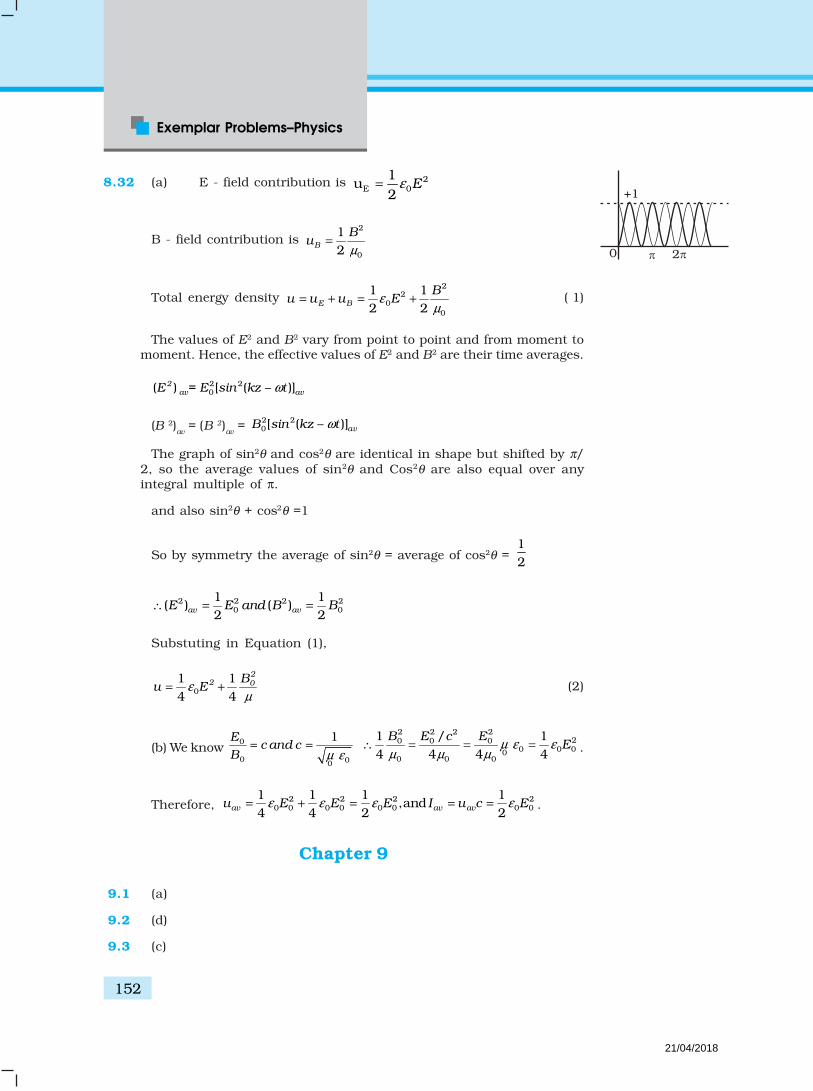
Exemplar Problems–Physics
152
8.32 (a) E - field contribution is 2E 0
1u
2E= ε
B - field contribution is 2
0
12B
Bu
µ=
Total energy density 2
20
0
1 12 2E B
Bu u u Eε
µ= + = + ( 1)
The values of E2 and B2 vary from point to point and from moment tomoment. Hence, the effective values of E2 and B2 are their time averages.
2 20( ) [ ( – )]2
av avE = E sin kz tω
(B 2)av
= (B 2)av = 2 2
0[ ( – )]avB sin kz tω
The graph of sin2θ and cos2θ are identical in shape but shifted by π/2, so the average values of sin2θ and Cos2θ are also equal over anyintegral multiple of π.
and also sin2θ + cos2θ =1
So by symmetry the average of sin2θ = average of cos2θ = 12
2 2 2 20 0
1 1( ) ( )
2 2av avE E and B B∴ = =
Substuting in Equation (1),
0
1 14 4
22 0B
u Eεµ
= + (2)
(b) We know 0
0 00
1Ec and c
B µ ε= =
2 2 2 220 0 0
0 0 000 0 0
1 / 14 4 4 4
B E c EEµ ε ε
µ µ µ∴ = = = .
Therefore, 2 2 2 20 0 0 0 0 0 0 0
1 1 1 1,and
4 4 2 2av av avu E E E I u c Eε ε ε ε= + = = = .
Chapter 9
9.1 (a)
9.2 (d)
9.3 (c)
+1
0 2
21/04/2018

153
Answers
9.4 (b)
9.5 (c)
9.6 (c)
9.7 (b)
9.8 (b)
9.9 (b)
9.10 (d)
9.11 (a)
9.12 (a), (b), (c)
9.13 (d)
9.14 (a), (d)
9.15 (a), (b)
9.16 (a), (b), (c)
9.17 As the refractive index for red is less than that for blue, parallelbeams of light incident on a lens will be bent more towards the axisfor blue light compared to red. Thus the focal length for blue lightwill be smaller than that for red.
9.18 The near vision of an average person is 25cm. To view an object withmagnification 10,
Dm
f= ⇒
2510
Df
m= = = 2.5 = 0.025m
140
0.025P = = diopters.
9.19 No. The reversibility of the lens makes equation.
9.20 Let the apparent depth be O1 for the object seen from µ2 then
21
1
O3hµ
µ=
If seen from µ3 the apparent depth is O2.
2 3 33 32 1
1 2 12 2
O O3 3 33
h h hh µ µ µµ µ
µ µ µµ µ
+ += = =+
Seen from outside, the apparent height is
21/04/2018

Exemplar Problems–Physics
154
3 23
1 hO +O
3µ
=
= 3 3
2 13
1 ++3 3h h
µ µ
µ µµ
1 2 3
1 1 1+ +
3h
= µ µ µ
9.21 At minimum deviation
( )sin2
sin2
mA D
Aµ
+ =
∴Given Dm = A
∴ 2sin cossin 2 2 2cos
2sin sin2 2
A AA A
A A= = =µ
∴ 3
cos2 2A
= or 2A
= 30° ∴ A = 60°
9.22 Let the two ends of the object be at distance u 1= u – L/2 andu
2 = u + L/2, respectively, so that |u1–u2|= L. Let the image of the two
ends be formed at v1 and v2, so that the image length would be
1 2–L v v′ = . Since1 1 1
–fu
or vu v f u f
+ = = the image of the two ends will
be at ( )
1– /2
– – /2f u L
vu f L
= , ( )
2/2
– /2f u L
vu f L
+=
+
Hence
( )
2
1 2 2 2| – |
/4–
f LL v v
Lu f′ = =
×
Since the object is short and kept away from focus, we haveL2/4 << (u –f )2
Hence finally
( )
2
2 .–
fL L
u f′ =
9.23 Refering to the Fig., AM is the direction of incidence ray before liquidis filled. After liquid is filledm, BM is the direction of the incident ray.Refracted ray in both cases is same as that along AM.
O
3
2
1
h/3
h/3
h/3
O3
O2
O1
21/04/2018

155
Answers
1 sin sin
sin sini i
rµ α= =
2 2
–sin
( – )
a Ri
d a R=
+ and
2 2sin cos(90 – )
( – )
a R
d a Rα α
+= =
+
Substuting, we get2 2
2 2
( – )
( ) – ( – )
a Rd
a R a R
µ
µ=
+
9.240.5
O O
50.0
If there was no cut then the object would have been at a height of0.5 cm from the principal axis 00′.Consider the image for this case.
1 1 1–
v u f=
1 1 1 1 1 1–50 25 50v u f
∴ = + = + =
∴ v = 50 cm.
Magnification is m = 50–
50v
u= = –1.
Thus the image would have been formed at 50 cm from the pole and0.5 cm below the principal axis.Hence with respect to the X axis passing through the edge of the cutlens, the co-ordinates of the image are
(50 cm, –1 cm)
9.25 From the reversibility of u and v, as seen from the formula for lens,
1 1 1–
f v u=
It is clear that there are two positions for which there shall be an imageon the screen.Let the first position be when the lens is at O.Given –u + v = D⇒ u = –(D – v)Placing it in the lens formula
1 1 1–D v v f
+ =
O
90 -
A BC
id
Ma a
R R
21/04/2018
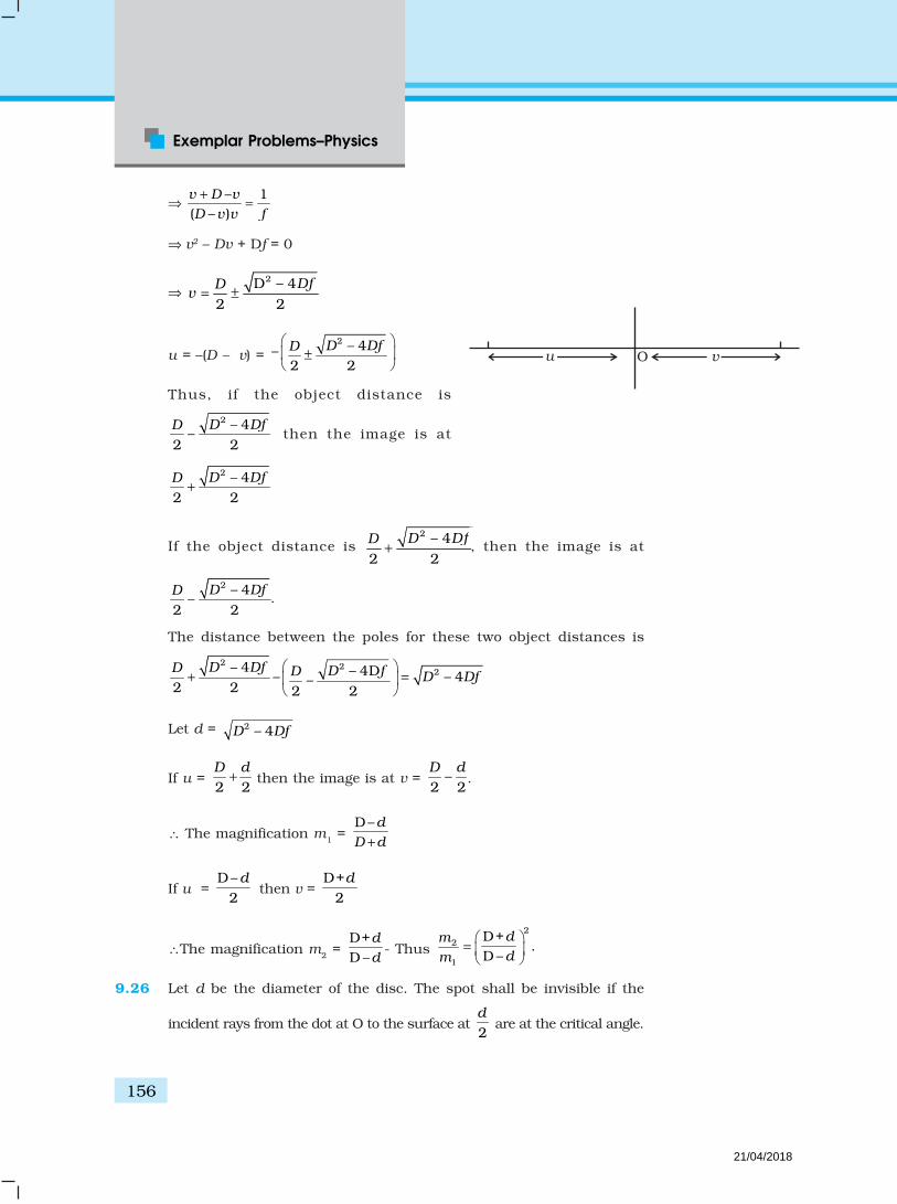
Exemplar Problems–Physics
156
⇒ – 1
( – )v D v
D v v f
+=
⇒ v2 – Dv + Df = 0
⇒ 2D – 4
2 2
DfDv = ±
u = –(D – v) = 2 – 4–
2 2D DfD
±
Thus, if the object distance is
2 – 4–
2 2
D DfD then the image is at
2 – 4
2 2
D DfD+
If the object distance is 2 – 4
2 2
D DfD+ , then the image is at
2 – 4– .
2 2
D DfD .
The distance between the poles for these two object distances is
2 22– 4 – 4D– – 4–2 2 2 2
D DfD D fD D Df
+ =
Let d = 2 – 4D Df
If u = 2 2D d
+ then the image is at v = –2 2D d
.
∴ The magnification m1 = D–d
D d+
If u = D–
2d
then v = D+
2d
∴The magnification m2 = D+D –
d
d- Thus
22
1
D+.
D –dm
dm
=
9.26 Let d be the diameter of the disc. The spot shall be invisible if the
incident rays from the dot at O to the surface at 2d
are at the critical angle.
u vO
21/04/2018

157
Answers
Let i be the angle of incidence.
Then sin i = 1µ
Now, /2d
h = tan i
⇒ –1
2tan –12d
h i h µ = =
∴2
2
–1
hd
µ= .
9.27 (i) Let the power at the far point be Pf for the normal relaxed eye.
Then Pf =
1 1 10.1 0.02f
= + = 60 D
With the corrective lens the object distance at the far point is ∞. Thepower required is
1 1 150D
0.02fPf
′ = = + =′ ∞
The effective power of the relaxed eye with glasses is the sum of the eyeand that of the glasses P
g.
∴ fP ′ = Pf + Pg
∴ Pg = – 10 D.
(ii) His power of accomadation is 4 diopters for the normal eye. Let thepower of the normal eye for near vision be P
n.
Then 4 = Pn – P
f or P
n = 64 D.
Let his near point be xn, then
1 1 164 or 50 64
0.02n nx x+ = + =
114,
nx=
∴ xn = 1
0.07m14
(iii) With glasses 4 54n fP P′ ′= + =
1 1 154 50
0.02n nx x= + = +
′ ′
14,
nx=
′
∴ 1
0.25m4nx ′ = = .
21/04/2018

Exemplar Problems–Physics
158
9.28 Any ray entering at an angle i shall be guided along AC if the anglethe ray makes with the face AC ( φ ) is greater than the critical angle.
⇒ sin ≥ 1µ
⇒ cos r ≥ 1µ
Or, 1 – cos2r ≤ 1 – 2
1µ
i.e. sin2r ≤ 1 – 2
1µ
Since sin i = µ sin r
2
1µ
sin2i ≤ 1 – 2
1µ
Or, sin2i ≤ µ2 – 1
The smallest angle φ shall be when i = 2π
. If that is greater than the
critical angle then all other angles of incidence shall be more than thecritical angle.Thus 1 ≤ µ2 –1Or, µ2 ≥ 2
⇒ µ ≥ 2
9.29 Consider a portion of a ray between x and x + dx inside the liquid. Letthe angle of incidence at x be θ and let it enter the thin column at heighty. Because of the bending it shall emerge at x + dx with an angle θ + dθand at a height y + dy. From Snell’s lawµ(y) sin θ = µ(y+dy) sin (θ+dθ)
or µ(y) sinθ ( )d
y dydy
µµ
+
(sinθ cosdθ + cosθ sin dθ )
( )sin ( )cos sind
y y d dydy
µµ θ µ θ θ θ+ +
or µ(y) cosθdθ –
sind
dydy
µθ
dθ –1
tand
dydy
µθ
µ
But tanθ = dx
dy(from the fig.)
A C
DB
ri
dx
dyy
+ d
( )y + dy
21/04/2018

159
Answers
+ d
rR
M
dr
r + dr r
∴ dθ = –1 ddx
dy
µ
µ
∴ θ = –1 d
o
ddx
dy
µ
µ = –1 dd
dy
µ
µ
9.30 Consider two planes at r and r + dr. Let the light be incident at anangle θ at the plane at r and leave r + dr at an angle θ +dθ
Then from Snell’s law
n(r) sinθ = n(r + dr) sin (θ + dθ )
⇒ n(r) sinθ ( )dn
n r drdr
+
(sinθ cos dθ + cosθ sin dθ )
( )dn
n r drdr
+
(sinθ + cosθ dθ )
Neglecting products of differentials
( ) ( )dn
n r sin n r sin drdr
θ θ + sinθ + n(r) cosθdθ
⇒ – tan ( )dn d
n rdr dr
θθ =
⇒ 2 2 2
2 2tan 1
GM d dGM
r c dr drrc
θ θθ
= ≈+
∴ 2 2
0 –
2GM tanodr
dc r
θ θθ
∞
∞
=
Now r2 = x2 +R2 and tanθ = R
x
2rdr = 2xdx
322 20 – 2
2GM
( )
oR xdx
dc x
x R
θ
θ∞
∞
=
+
Put x = R tan φ
dx = R Sec2 φ d φ
∴
/2 2
0 2 3 3– /2
2GMR sec =
c secR d
R
π
π
φ φθ
φ
= /2
2– /2
2cos
GMd
Rc
π
π
φ φ = 2
4GM
R c
21/04/2018

Exemplar Problems–Physics
160
9.31 As the material is of refractive index –1, θr is negative and rθ ′ positive.
Now i r rθ θ θ ′= =
The total deviation of the outcoming ray from the incoming ray is 4θi.
Rays shall not reach the receiving plate if
34
2 2i
π πθ≤ ≤ (angles measured clockwise from the y axis)
38 8i
π πθ≤ ≤
Now sin i
x
Rθ =
–1 3sin
8 8x
R
π π≤ ≤
Or, 3
8 8x
R
π π≤ ≤
Thus for 38 8
R Rx
π π≤ ≤ light emitted from the source shall not reach
the receiving plate.
9.32 (i) The time required to travel from S to P1 is
2 2 21
1 2
11
2
SP u b u bt
c c c u
+ = = +
assuming b << u
0
The time required to travel from P1 to O is
2 2 21
2 2
11
2
P O v b v bt
c c c v
+ = = +
The time required to travel through the lens is
( –1) ( )l
n w bt
c= where n is the refractive index.
Thus the total time is
21 1 1 1( –1) ( )
2t u v b n w b
c u v
= + + ++
. Put 1 1 1D u v
= +
Then 2 2
0
1 1( –1)
2b b
t u v n wc D α
= + + + +
Fermet’s principle gives
2( –1)0 –
dt b n b
db CD cα= =
2( – 1)α = n D
P1
S u v O
b
y
x
i R
x
o
r
i
r
Receiving plate
21/04/2018
161
Answers
Thus a convergent lens is formed if 2( – 1)α = n D . This is independantof b and hence all paraxial rays from S will converge at O (i.e. for raysb << n and b << v).
Since 1 1 1D u v
= + , the focal length is D.
(ii) In this case
t = ( )2
21
1 11
2 Db k
u v k lnnc b
+ + + −
10 – ( –1)dt b k
ndb D b
= =
⇒ b2 = (n – 1) k1D
∴ b = 1( –1)n k D
Thus all rays passing at a height b shall contribute to the image. The raypaths make an angle
1 1 12 2
( –1) ( –1) ( –1)( ) ( )
n k Db n k uv n k u
v v v u v u v vβ = = =
+ + .
Chapter 10
10.1 (c)
10.2 (a)
10.3 (a)
10.4 (c)
10.5 (d)
10.6 (a), (b), (d)
10.7 (b), (d)
10.8 (a), (b)
10.9 (a), (b)
10.10 Yes.
10.11 Spherical.
10.12 Spherical with huge radius as compared to the earth’s radius sothat it is almost a plane.
10.13 Sound wave have frequencies 20 Hz to 20 kHz. The correspondingwavelengths are 15m and 15mm, respectively. Diffraction effectsare seen if there are slits of width a such that.
.α λ
21/04/2018

Exemplar Problems–Physics
162
For light waves, wavelengths 10–7m. Thus diffraction effects willshow when
–710a m.whereas for sound they will show for
15mm 15ma< < .
10.14 The linear distance between two dots is –22.54cm 0.84 10 cm.
300l = ×
At a distance of Z cm this subtends an angle.–2
–4
0.84 10 cm/ 14.5cm
5.8 10l
l z zφφ
×∴ = =
× .
10.15 Only in the special cases when the pass axis of (III) is parollel to (I) or(II) there shall be no light emerging. In all other cases there shall belight emerging because the pass axis of (II) is no longer perpendicularto the pass axis of (III).
10.16 Polarisation by reflection occurs when the angle of incidence is the
Brewster’s angle i.e. 2
1
tan B
n
nθ = where n2 < n1.
When light travels in such a medium the critical angle is 2
1
sin c
n
nθ =
where n2 < n
1.
As |tan θB|>|sin θc|for large angles, B Cθ θ< .
Thus, polarisation by reflection shall definitely occur.
10.17 min1.222sin
dλ
β=
where β is the angle subtended by the objective at the object.
For light of 5500 A
–7
min
1.22 5.5 10m
2sind
β
× ×=
For electrons accelerated through 100V the deBroglie wavelengthis
–91.2270.13nm 0.13 10 m
100
h
pλ = = = = ×
–10
min
1.22 1.3 10'
2sind
β
× ×∴ =
21/04/2018

163
Answers
–10
min
1.22 1.3 10'
2sind
β
× ×∴ =
–10–3min
–7min
' 1.3 100.2 10
5.5 10d
d
×= ×
×
10.18 T2P = D + x, T1 P = D – x
2 21 1 1 1S P (S T ) (PT )= +
= [D 2 + (D – x)2]1/2
S2P = [D 2 + (D + x)2]1/2
Minima will occur when
[D 2 + (D + x)2]1/2 – [D2 + (D – x)2]1/2 =2λ
If x = D
(D2 + 4D2)1/2 =2λ
(5D2)1/2 =2λ
,2 5
Dλ
∴ = .
10.19 Without P:
11A A A⊥= +
1 2 0 0A A A A sin( – )+A sin( – )kx t kx tω ω φ⊥ ⊥ ⊥ ⊥ ⊥= + = +
(1) (2)11 11 11A A A= +
011 11A A [sin( – ) sin( – ]kx wt kx tω φ= + +
where 0A ⊥ , 011A are the amplitudes of either of the beam in ⊥ and
11 polarizations.
∴ Intensity =
( )2 2 2 2 2 20 0
average11[sin (1+cos 2sin )+sin ( – ) sin ]–A A kx tkx wt φ φ ω φ
⊥= ++
2 20 011
1 .2(1+cos )A A2
φ⊥
= +
21/04/2018

Exemplar Problems–Physics
164
= 220 0 0
11average average.(1 cos )sinceA A Aφ
⊥ ⊥+ =
With P:
Assume 2A⊥ is blocked:
Intensity = 1 2 2 1 211 11(A A ) (A )⊥+ +
2 20 0 1(1 cos ) .A A
2φ
⊥ ⊥= + +
Given: I0 =
204 A⊥= Intensity without polariser at principal maxima.
Intensity at principal maxima with polariser
20 12A
2⊥
= +
05
I8
=
Intensity at first minima with polariser
( )
2020 A
A 1 –12⊥
⊥= +
0
8I
= .
10.20 Path difference = 2 sin ( –1)d lθ µ+
∴ For principal maxima,
2 sin 0.5 0d lθ + =
0– –1
sin4 16 4
l dl
dθ = = =
∴ 0OP tan –16D
D θ= ≈
For the first minima:
∴ 12 sin +0.5 = 2
d lλ
θ ±
21/04/2018

165
Answers
1/2 – 0.5 /2 – /8 1 1
sin –2 2 4 16
l
d
λ λ λθ
λ
± ±= = = ±
On the positive side: 3
sin16
θ + =
On the negative side: – 5
sin –16
θ =
The first principal maxima on the positive side is at distance
2 2 2
sin 3tan
1 – sin 16 – 3D D D
θθ
θ
++ = = above O.
In the –ve side, the distance will be –
2 2
5tan
16 – 5D θ = below O.
10.21 (i) Consider the disturbances at R1 which is a distance d from A. Let
the wave at R1 because of A be Y
A = a cos ωt. The path difference of
the signal from A with that from B is λ/2 and hence the phasedifference is π.
Thus the wave at R1 because of B is
cos( – ) – cos .By a t a tω π ω= =
The path difference of the signal from C with that from A is λ andhence the phase difference is 2π.
Thus the wave at R1 because of C is y
c = a cos ωt.
The path difference between the signal from D with that of A is
( )2
2 /22
d dλ
λ
+ − −
1/2
2124
d dd
λλ = − ++
1/22
2128
d dd
λλ = − ++
If d >>λ the path difference 2λ
and hence the phase difference
is π.
R1 A B C
D
/2
/2 /2
R2
21/04/2018

Exemplar Problems–Physics
166
cosDy a tω∴ = − .
Thus, the signal picked up at R1 is
yA + y
B + y
C + y
D = 0
Let the signal picked up at R2 from B be y
B = a1 cos ωt.
The path difference between signal at D and that at B is λ/2.
1– cosDy a t∴ = ω
The path difference between signal at A and that at B is
1/22 22
2( ) 1
2 4d d d d
d
λ λ + − = −+
2
2
18 d
λ
∴ The phase difference is 2
2
2. 0.
8 4d d
π λ πλφ
λ= =
Hence, yA = a1 cos (ωt-φ)
Similarly, yC = a1 cos (ωt-φ)
∴ Signal picked up by R2 is
yA + y
B + y
C + y
D = y = 2a
1 cos (ωt-φ)
2 2 21| | 4 cos ( – )y a tω φ∴ =
212aI∴ =
Thus R1 picks up the larger signal.
(ii) If B is switched off,R
1 picks up y = a cos ω t
121
2RI a∴ =
R2 picks up y = a cos ω t
221
12
RI a∴ =
Thus R1 and R
2 pick up the same signal.
(c) If D is switched off.R
1 picks up y = a cos ω t
121
2RI a∴ =
R2 picks up y = 3a cos ω t
221
92
RI a∴ =
Thus R2 picks up larger signal compared to R
1.
(iv) Thus a signal at R1 indicates B has been switched off and an
enhanced signal at R2 indicates D has been switched off.
21/04/2018

167
Answers
10.22 (i) Suppose the postulate is true, then two parallel rays wouldproceed as shown in Fig. 1. Assuming ED shows a wave frontthen all points on this must have the same phase. All pointswith the same optical path length must have the same phase.
Thus – BC – CDr r r rAEε µ ε µ=
or ( )r rBC CD AEε µ= −
BC > 0, CD > AEAs showing that the postulate is reasonable. If however, the lightproceeded in the sense it does for ordinary material (viz. in thefourth quadrant, Fig. 2)
Then – BC – CDr r r rAEε µ ε µ=
or, ( )r rBC CD AEε µ= −
As AE > CD, BC < Oshowing that this is not possible. Hence the postalate is correct.
(ii) From Fig. 1.BC = AC sin θi and CD-AE = AC sin θr:
Since ( )r r BCAE CDε µ− =−
–n sin θr = sin θi.
10.23 Consider a ray incident at an angle i. A part of this ray is reflectedfrom the air-film interface and a part refracted inside. This is partlyreflected at the film-glass interface and a part transmitted. A part ofthe reflected ray is reflected at the film-air interface and a parttransmitted as r
2 parallel to r
1. Of course succesive reflections and
transmissions will keep on decreasing the amplitude of the wave. Hencerays r
1 and r
2 shall dominate the behavior. If incident light is to be
transmitted through the lens, r1 and r
2 should interfere destructively.
Both the reflections at A and D are from lower to higher refractiveindex and hence there is no phase change on reflection. The opticalpath difference between r
2 and r
1 is
n (AD + CD) – AB.
If d is the thickness of the film, then
cosd
AD CDr
= =
sinAB AC i=
tan2
ACd r=
2 tanAC d r∴ =
Hence, AB = 2d tanr sini
Thus the optical path difference is
i i
ir
ED
CB air
mediumA
E
D
C
Bair
medium
A
Fig.1
Fig. 2
21/04/2018

Exemplar Problems–Physics
168
2 2 tan sincos
dn d r i
r−
sin sin2. 2 sin
sin cos cosi d r
d ir r r
= −
21 sin2 sin
sin cosr
dr r
−=
= 2nd cosr
For these waves to interefere destructively this must be λ/2.
2 cos2
nd rλ
=
or nd cos r = λ/4
For a camera lens, the sources are in the vertical plane and hence
0i r
4nd
λ∴ .
5500 A1000 A
1.38 4d =
×
Chapter 11
11.1 (d)
11.2 (b)
11.3 (d)
11.4 (c)
11.5 (b)
11.6 (a)
11.7 (a)
11.8 (c)
11.9 (c), (d)
11.10 (a), (c)
11.11 (b), (c)
Air =1n
Film = 1.38n
Glass = 1.5n
ii
r1r2
r
D
CB
A
21/04/2018

169
Answers
11.12 (a), (b), (c)
11.13 (b), (d)
11.142
/ / 8 :12p d x p
p p
m Ep p
m E
α αλ λ = = =
11.15 (i) Emax = 2hν – φ
(ii) The probability of absorbing 2 photons by the same electron isvery low. Hence such emissions will be negligible.
11.16 In the first case energy given out is less than the energy supplied. Inthe second case, the material has to supply the energy as the emittedphoton has more energy. This cannot happen for stable substances.
11.17 No, most electrons get scattered into the metal. Only a few come out ofthe surface of the metal.
11.18 Total E is constant
Let n1 and n2 be the number of photons of X-rays and visible region
n1E
1 = n
2E
2
1 21 2
hc hcn n
λ λ=
1 1
2 2
.n
n
λ
λ=
1
2
1500
n
n= .
11.19 The momentum is transferred to the metal. At the microscopic level,atoms absorb the photon and its momentum is transferred mainlyto the nucleus and electrons. The excited electron is emitted.Conservation of momentum needs to be accounted for themomentum transferred to the nucleus and electrons.
11.20 Maximum energy = hν – φ
11230 1230– –
2600 400φ φ
=
12301.02eV.
1200φ = =
11.21 x p∆ ∆
–34–25
–9
1.05 10 Js1.05 10
10 mp
x
×∆ = ×
∆
21/04/2018
Exemplar Problems–Physics
170
2 –25 2 2 2–19
–31
(1.05 10 ) 1.05 1.0510 J=
2 2 9.1 10 18.2 18.2 1.6p
E eVm
×= = = ×
× × ×
= 3.8 × 10⁻²eV
11.22 I = nAn
A = nBν
B
2A B
B A
n
n
ν
ν= =
The frequency of beam B is twice that of A.
11.23 A B
A B c c
h h h hp p
λ λ λ λ= + = + = =
if p
A, p
B > 0 or p
A, p
B < 0
or A Bc
A B
λ λλ
λ λ=
+
If pA > 0, pB < 0 or p
A < 0, pB > 0
–.
B Ac
A B c
hp h= =
λ λ
λ λ λ
..
–B A
c
A B
λ λλ
λ λ=
11.24 2d sinθ = λ = d =10–10 m.
–34–21
–10 –10
6.6 106.6 10 kg m/s
10 10h
p×
= = = ×
–24 2 2–19 –2
–27
(6.6 10 ) 6.61.6 10 1.6 10 V
2 (1.7 10 ) 2 1.7E e
×= × × = × ×
× × ×
= 20.5 × 10⁻²eV = 0.21eV
11.25 6 × 1026 Na atoms weighs 23 kg.
Volume of target = (10–4 × 10⁻³) = 10–7m3
Density of sodium = (d) = 0.97 kg/m3
Volume of 6 × 1026 Na atoms = 323m
0.97 = 23.7 m3
Volume occupied of 1 Na atom 3
26
23m
0.97 6 10=
× × = 3.95 × 10⁻²⁶ m3
No. of sodium atoms in the target = –7
–26
103.95 10×
= 2.53 × 10¹⁸
Number of photons/s in the beam for 10–4 m2 = n
21/04/2018

171
Answers
Energy per s nhν = 10–4 J × 100 = 10–2 W
hν (for λ = 660nm) = 1234.5
600
= 2.05eV = 2.05 × 1.6 × 10–19 = 3.28 × 10⁻¹⁹J.
n = –2
16–19
103.05 10 /s
3.28 10= ×
×
n = 17 16110 3.1 10
3.2× = ×
If P is the probability of emission per atom, per photon, the numberof photoelectrons emitted/second
16 183.1 10 2.53 10P= × × × ×
Current = P × 3.1 × 10+16 × 2.53 × 1018 × 1.6 × 10–19 A
= P × 1.25 × 10+16 A
This must equal 100µA or
P = –6
16
100 101.25 10+
×
×
∴ P = 8 × 10–21
Thus the probability of photemission by a single photon on a singleatom is very much less than 1. (That is why absorption of twophotons by an atom is negligible).
11.26 Work done by an external agency = 2 2
20 0
1 1 1. .
4 4 4 4d
q qdx
dxπε πε
∞
+ =
With d = 0.1nm, energy = –19 9
–10 –19
(1.6 10 ) 9 10eV
4(10 ) 1.6 10× × ×
× ×
= 1.6 9
eV4×
= 3.6 eV
11.27 (i) Stopping potential = 0 at a higher frequency for B. Hence it hasa higher work function.
(ii) Slope = h
e = 14
2(10 – 5) 10×
for A.
= 14
2.5(15 –10) 10×
for B.
21/04/2018

Exemplar Problems–Physics
172
–19–14 –341.6 10
2 10 6.04 10 Js for A5
h×
= × × = ×
–19 –141.6 10 2.5 105
× × ×= = 8 × 10–34 Js for B.
Since h works out differently, experiment is not consistent withthe theory.
11.28 mAv = m
Av
1 + mBv
2
2 2 21 2
1 1 12 2 2A A Bm v m v m v= +
21 1
1 1( – )( )
2 2A A B Bm v v v v m v/ /
∴ + =/ /
∴ v + v1 = v
2
or v = v2 – v
1
1 2
– 2, andA B A
A B A B
m m mv v v v
m m m m
∴ = = + +
initialA
h
m v∴ =λ
final
( )( – )
A B
A A BA
h m mh
m m m vm vλ
+= =
)– 1
–A B
A BA
m mh
m mm vλ
+ ∴ ∆ =
11.29 (i) 195 10 /( / )
dN Psec
dt hc λ= = ×
(ii) 02.49eV : Yes.hc
W= >λ
(iii)2
02.4
rP t W
d
π
π∆ = , 28.4st∆ =
(iv)2
2 24
rdNN t
ddt
π
π
= × × ∆ =
r
d
21/04/2018
173
Answers
Chapter 12
12.1 (c)
12.2 (c)
12.3 (a)
12.4 (a)
12.5 (a)
12.6 (a)
12.7 (a)
12.8 (a), (c)
12.9 (a), (b)
12.10 (a), (b)
12.11 (b), (d)
12.12 (b), (d)
12.13 (c), (d)
12.14 Einstein’s mass-energy equivalence gives E = mc2. Thus the mass
of a H-atom is 2p e
Bm m
c+ − where B ≈ 13.6eV is the binding energy.
12.15 Because both the nuclei are very heavy as compared to electronmass.
12.16 Because electrons interact only electromagnetically.
12.17 Yes, since the Bohr formula involves only the product of the charges.
12.18 No, because accoding to Bohr model, 2
13.6–nE
n= ,
and electons having different energies belong to different levelshaving different values of n. So, their angular momenta will be
different, as .2nh
mvrπ
=
12.19 The ‘m ’ that occurs in the Bohr formula 4
2 20
–8n
meE
n hε= is the
reduced mass. For H-atom m ≈ me. For positronium /2em m≈ .
Hence for a positonium E1≈ – 6.8eV.
21/04/2018

Exemplar Problems–Physics
174
12.20 For a nucleus with charge 2e and electrons of charge –e, the levels
are 4
2 2 20
4–
8n
meE
n hε= . The ground state will have two electrons each
of energy E, and the total ground state energy would by –(4×13.6)eV.
12.21 v = velocity of electron
a0= Bohr radius.
∴Number of revolutions per unit time 02π=
a
v
∴ Current 02π=
a
ve.
12.22 νmn ( )
22 2
1 1cRZ
nn p
−=
+ ,
where m = n + p, (p = 1, 2, 3, ...) and R is Rydberg constant.
For p << n.
–22
2 2
1 11mn
pcRZ
n nnν
= −+
22 3 2
1 2 1–mn
pcRZ
n n nν
= −
22
3 3
2 2mn
p cRZcRZ p
n nν
=
Thus, νmn are approximately in the order 1, 2, 3...........
12.23 H γ in Balmer series corresponds to transition n = 5 to n = 2. So the
electron in ground state n = 1 must first be put in state n = 5.Energy required = E1 – E5 = 13.6 – 0.54 = 13.06 eV.
If angular momentum is conserved, angular momentum of photon= change in angular momentum of electron
–345 2– 5 – 2 3 3 1.06 10= = = = × ×L L
= 3.18 × 10⁻³⁴ kg m2/s.
12.24 Reduced mass for 1 –1
e eH e
e
m mH m
m MM
µ = =
+
21/04/2018

175
Answers
Reduced mass for 1 – 1 – 12 2 2
µ = = +
e e eD e e
m m mD m m
M M M
( – ) .ij i jh E E=ν α µ Thus, 1
λ αµ
ij
If for Hydrogen/Deuterium the wavelength is /λ λH D
–1 11 –1
2 18402
λ µ
λ µ
= + ×
D H e
H D
m
M
(0.99973)λ λ= ×D H
Thus lines are 1217.7 Å , 1027.7 Å, 974.04 Å, 951.143 Å.
12.25 Taking into account the nuclear motion, the stationary state
energies shall be, 2 4
2 2 20
1–
8n
Z eE
h n
=
µ
ε. Let Hµ be the reduced mass
of Hydrogen and µD that of Deutrium. Then the frequency of the
1st Lyman line in Hydrogen is 4 4
2 2 2 20 0
31.1 –
8 4 84
µ µν
ε ε
= =
H HH
e eh
h h Thus
the wavelength of the transition is 4
2 30
3.
4 8H
H
e
h c=
µλ
ε The wavelength
of the transition for the same line in Deutrium is 4
2 30
34 8
DD
e
h c=
µλ
ε.
–λ λ λ∴ ∆ = D H
Hence the percentage difference is
– –100 100 100
λ λ λ µ µ
λ λ µ
∆× = × = ×D H D H
H H H
–( ) ( )
100/( )
e D e H
e D e H
e H e H
m M m M
m M m M
m M m M
+ += ×
+
– 1 100e H D
e D H
m M M
m M M
+ = × +
Since me << M
H < M
D
21/04/2018

Exemplar Problems–Physics
176
1 /100 –1 100
1 /e HH D
e DH D H
m MM M
m MM M
λ
λ
+ ∆ × = × × +
= –1 100(1 / )(1 / ) –1 × + + e H e Dm M m M
(1 – –1 100e e
H D
m m
M M
+ ×
eH D
mM M
1 1– 100
≈ ×
–31–27 –27
1 19.1 10 100–
1.6725 10 3.3374 10
= × × × ×
[ ]–49.1 10 1000.5979 – 0.2996= × ×
= 2.714 × 10⁻² %
12.26 For a point nucleus in H-atom:
Ground state:2 2
20
1, – .
4B B
mv emvr
r r πε= =
2 2
2 2 20
1 1.
4πε
∴ = +
B B B
em
m r r r
20
2
4. 0.51ABr
m e
°πε∴ = =
Potential energy
2 22
2 2 20
1 1– . –27.2 ; . . 13.6eV
2 24 2B B B
mveeV K E m
rr m r mr
= = = = = +
π
For an spherical nucleus of radius R,
If R < rB, same result.
If R >> rB: the electron moves inside the sphere with radius
Br ′ ( Br ′ = new Bohr radius).
Charge inside 3
4
3B
B
rr e
R
′′ =
21/04/2018
177
Answers
2 30
32
4B
B
Rr
m re
πε ′∴ = ′
4 3(0.51A). .Br R°
′ = 10°
=R A
4510(A)°
=
1/4(510) A .Br R°
′∴ ≈ <
22 2 2
1 1. . .
2 2 2= = =
′ ′B B
mK E mv
m r m r
22 2
1/22 2
(0.51) 3.54. (13.6eV) 0.16eV
(510) 22.62B
B B
r
mr r
= = = =
′
2 2 2
30
– 3. .4 2πε
′= +
Be r R
P ER
B B
B
e r r R
r R
2 2 2
30
1 ( – 3..4πε
′= +
0.51( 510 – 300)(27.2eV)1000
= +
–141(27.2eV). –3.83eV.
1000= + =
12.27 As the nucleus is massive, recoil momentum of the atom may beneglected and the entire energy of the transition may be consideredtransferred to the Auger electron. As there is a single valence electronin Cr, the energy states may be thought of as given by the Bohr model.
The energy of the nth state 22
1–nE Z R
n= where R is the Rydberg
constant and Z = 24.
The energy released in a transition from 2 to 1
is 2 231.1 –
44 ∆ = =
E Z R Z R The energy required to eject a n = 4
electron is 24
116
=E Z R .
21/04/2018

Exemplar Problems–Physics
178
Thus the kinetic energy of the Auger electron is
2 3 1. –
4 16
=
K E Z R 2116
= Z R
1124 24 13.6eV
16= × × ×
= 5385.6 eV
12.28 mpc2 = 10–6 × electron mass × c2
–610 0.5MeV≈ ×
–6 –1310 0.5 1.6 10≈ × × ×
–190.8 10 J≈ ×
–34 8
2 –19
10 3 100.8 10
× ×= =
×p p
c
m c m c
–74 10 m Bohr radius.≈ × >>
2
20
1exp(– )
4e
rr r
λλ
πε
= + F
where –1 –74 10 m B
p
rm c
λ = ≈ × >>
1. 1λ λ∴ << <<B
B
i e rr
2
0
exp(– )( ) – .
4λ
πε=
e rU r
r
=mvr ∴ =vmr
2 2
20
1Also :
4mv e
r r r
λ
πε
=≈ +
2 2
3 20
14
λ
πε
∴ = +
e
mr r r
2 22
0
[ ]4
λπε
∴ = +
er r
m
21/04/2018

179
Answers
If 02
40; .
πελ = = =Br r
m e
2 2
0
.4πε
= B
er
m
Since –1 ,putλ δ>> = +B Br r r
2 2 2( 2 );negectδ λ δ δ δ∴ = + + + +B B B Br r r r
or 20 (1 2 )λ δ λ= + +B Br r
22 2–(1 – 2 ) – since 1
1 2B
B B B B
B
rr r r r
r
λδ λ λ λ λ
λ= ≈ = <<
+
2
0
exp(– – )( ) – .
4λδ λ
πε δ∴ =
+B
B
e rV r
r
2
0
1 1 –( ) – .(1 – )4
δλ
πε
∴ =
B
BB
eV r r
rr
(–27.2eV)≅ remains unchanged.
21. –
2=K E mv
2
2
1.
2m
mr=
2
22( )Br δ=
+
2
2
21 –
2 BBrr
δ =
[ ](13.6eV) 1 2 Brλ= +
Total energy = [ ]2 2
20
– 1 24 2 B
B B
er
r rλ
πε+ +
[ ]–27.2 13.6 1 2 eVBrλ= + +
Change in energy 13.6 2 eV 27.2 eVB Br r= × =λ λ
12.29 Let 2ε δ= +
1 2 0 02 2
0
.4q q R R
Fr r
δ δ
δ δπε + += = ∧ , where 1 2
0
,4q q
π ε= ∧ –19 2 9(1.6 10 ) 9 10∧ = × × ×
–2923.04 10= ×
21/04/2018

Exemplar Problems–Physics
180
2
=mv
r
2 01
δ
δ+
∧=
Rv
mr
(i) mvr n= , 1/2
1/2 /2
0
mn nr r
Rmv m
+ = = ∧
δδ
Solving this for r, we get
12 2 1–
0n
nr
m R
δ
δ
=
∧
For n = 1 and substituting the values of constant, we get
12 1–
10
rm R
δ
δ
=
∧
12 –68 2.9
1 –31 –28 19
1.05 109.1 10 2.3 10 10
r+
×=
× × × × = 8 × 10–11 = 0.08 nm
(< 0.1 nm)
(ii) n
n
nv
mr=
=
11–
02 2
m Rn
n
δ δ ∧
. For n = 1, 11
vmr
=
= 1.44 × 10⁶ m/s
(iii) K.E. =2 –191
19.43 10 J=5.9eV
2mv = ×
P.E. till 00
–RR
∧=
P.E. from R0 to r
00
00 2 1
1–1 –
r r
RR
dr RR
r r
δδ
+δ +δ
∧ = + ∧ = + δ
01 1
0
1 1––
1R
r R
δ
+δ +δ
∧ = + δ
01
0
1– –1
R
Rr
δ
+δ
∧=
+ δ
01
0 0
1 1. . – –
1R
P ER Rr
δ
+δ
∧ + δ= +
+ δ
21/04/2018

181
Answers
–1.90–0.9
0
1.9. . – –
–0.9R
P ERr
∧=
–18 0.92.310 [(0.8) –1.9]
0.9= × J = – 17.3 eV
Total energy is (–17.3 + 5.9) = –11.4 eV.
Chapter 13
13.1 (c)
13.2 (b)
13.3 (b)
13.4 (a)
13.5 (a)
13.6 (b)
13.7 (b)
13.8 (a), (b)
13.9 (b), (d)
13.10 (c), (d)
13.11 No, the binding energy of H13 is greater.
13.12
N
d N
d t
13.13 B has shorter mean life as λ is greater for B.
13.14 Excited electron because energy of electronic energy levels is in therange of eV, only not in MeV. as γ -radiation has energy in MeV.
21/04/2018

Exemplar Problems–Physics
182
13.15 2γ photons are produced which move in opposite directions toconserve momentum.
13.16 Protons are positively charged and repel one another electrically.This repulsion becomes so great in nuclei with more than 10 protonsor so, that an excess of neutrons which produce only attractiveforces, is required for stability.
13.17
No.
of
ato
ms
time
A
B
At t = 0, NA = N
O while N
B = 0. As time increases, N
A falls off
exponentially, the number of atoms of B increases, becomesmaximum and finally decays to zero at ∞ (following exponentialdecay law).
13.18 01ln
Rt
Rλ=
= 5760 16
ln0.693 12
= 5760 4
ln0.693 3
= 5760 4
2.303log0.693 3
× = 2391.12 years.
13.19 To resolve two objects separated by distance d, the wavelength λ ofthe proving signal must be less than d. Therefore, to detect separateparts inside a nucleon, the electron must have a wavelength lessthan 10–15 m.
andh hc
K pc K pcp
λλ
= ≈ ≈ =
34 8
–19 –15
6.63 10 3 10eV
1.6 10 10× × ×
=× ×
= 109 eV. = 1 GeV.
13.20 (a) 2311 Na : Z1 = 11, N1 = 12
∴ Mirror isobar of 2311 Na = 23
12 Mg .
21/04/2018

183
Answers
(b) Since Z2 > Z1, Mg has greater binding energy than Na.
13.2138 38 38
2.48 h 0.62 hS Cl Ar → →
At time t, Let 38S have N1(t ) active nuclei and 38Cl have N2(t) active
nuclei.
3811
d– rateof formation of Cl .Also
d 1
NN
tλ= =
21 2 1 1
d–
dN
N Nt
λ λ= +
But 1–1 0
tN N e λ=
1–21 0 2 2
d– –
dtN
N e Nt
λλ λ=
Multiplying by 2e td tλ and rearranging
2 2 2 1( – )2 2 2 1 0N d = Nt t te dN e t e dtλ λ λ λλ λ+
Integrating both sides.
2 2 1( – )0 1
2 1
NC
–t t
2N e eλ λ λλ
λ λ= +
Since at t = 0, N2 = 0, 0 1
2 1
C=––
N λ
λ λ
2 12 ( – )1
2 1
( –1)–
tt 02
NN e e
λ λλ λ
λ λ∴ =
2– , –1
2 1
( – )–
λ λλ
λ λ= t t0
2
NN e e
For maximum count, 02dN
dt=
On solving, 11 2
2
ln /( – )λ
λ λλ
=
t
2.48ln /(2.48 – 0.62)
0.62=
ln 4 2.303 log 41.86 1.86
= =
= 0.745 s.
13.22 From conservation of energy
22
2 2pn
n p
ppE B K K
m m− = + = + (1)
21/04/2018

Exemplar Problems–Physics
184
From conservation of momentum
+ =n p
Ep p
c(2)
If E = B, the first equation gives pn = p
p = 0 and hence the second
equation cannot be satisfied, and the process cannot take place.
For the process to take place, Let E = B + λ, where λ would be <<B.
Then : substituting for pn from Equation (2) into Equation (1),
( )( )22 2 21 1( ) /
2 2p n ppp p p E cp
m mλ = + = −+
22
2
22 02 λ
∴ − + =−
p p
E Ep p m
c c
22 2
22 / 4 / 8 2
4p
EE c E c m
cp
λ
± − −
∴ =
Since the determinant must be positive for pp to be real :
2 2
2 2
4– 8 02
E Em
c cλ
=−
Or, 2
2
416 λ =
Em
c,
2 2
2 24 4λ∴ = ≈
E B
mc mc.
13.23 The binding energy in H atom 4
2 20
13.6eV8me
Ehε
= = . (1)
If proton and neutron had charge e′ each and were governed bythe same electrostatic force, then in the above equation we wouldneed to replace electronic mass m by the reduced mass m ′ ofproton-neutron and the electronic charge e by e′ .
1836918
2 2M m
m m′ = = = .
∴ Binding energy 2 20
9182.2MeV
8m e
hε
′= = (given) (2)
Diving (2) by (1)
21/04/2018

185
Answers
4 2.2MeV918
13.6eVe
e
′ =
11e
e
′ ≈ .
13.24 Before β decay, neutron is at rest. Hence En = mnc
2, pn = 0
After β decay, from conservation of momentum:
= +p p pn p e
Or 0+ = = =p pp p p ep e p
Also,
12 4 2 2 2( )p p pE m c p c= + ,
1 12 4 2 2 2 4 22 2( ) ( )= + = +e e e e pE m c p c m c p c
From conservation of energy:
1 12 4 2 2 2 4 2 2 22 2( ) ( )+ + + =p e nm c p c m c p c m c
2 2 2936MeV, 938MeV, 0.51MeVp n em c m c m c≈ ≈ =
Since the energy difference between n and p is small, pc will besmall, pc << m
pc2, while pc may be greater than m
ec2.
2 22 2
2 4 –2
+p n
p
p cm c m c pc
m c
To first order 2 2– 938MeV – 936MeV 2MeVn ppc m c m c = =
This gives the momentum.
Then,
12 4 2 2 2 22( ) 936 2 936MeVp pE m c p c= + = +
12 4 2 2 2 22( ) (0.51) 2 2.06MeVe eE m c p c= + = +
13.25 (i) t1/2
= 40 min (approx).
(ii) Slope of graph = –λ
21/04/2018

Exemplar Problems–Physics
186
0 1 2 3 4
–1.04
–2.08
–3.11
–4.16
t(h)
ln(R/R )0So –4.16+3.11– 1.05h
1λ = =
So 1/20.693
0.66h 39.6min 40min( ).1.05
t or approx= = =
13.26 (i) SpSn
= (M119,70 + MH – M120,70)c
2
= (118.9058 + 1.0078252 – 119.902199)c2
= 0.0114362 c2
SpSb = (M120,70 + MH – M121,70)c
2
= (119.902199 + 1.0078252 – 120.903822)c2
= 0.0059912 c2
Since SpSn
> SpSb
, Sn nucleus is more stable than Sb nucleus.
(ii) It indicates shell structure of nucleus similar to the shellstructure of an atom. This also explains the peaks in BE/nucleon curve.
Chapter 14
14.1 (d)
14.2 (b)
14.3 (b)
14.4 (d)
14.5 (b)
14.6 (c)
14.7 (b)
14.8 (c)
14.9 (a), (c)
14.10 (a), (c)
14.11 (b), (c), (d)
14.12 (b), (c)
14.13 (a), (b), (d)
21/04/2018
187
Answers
14.14 (b), (d)
14.15 (a), (c), (d)
14.16 (a), (d)
14.17 The size of dopant atoms should be such as not to distort the puresemiconductor lattice structure and yet easily contribute a chargecarrier on forming co-valent bonds with Si or Ge.
14.18 The energy gap for Sn is 0 eV, for C is 5.4 eV, for Si is 1.1 eV and forGe is 0.7eV, related to their atomic size.
14.19 No, because the voltmeter must have a resistance very highcompared to the junction resistance, the latter being nearly infinite.
14.20
14.21 (i) 10 × 20 × 30 × 10–3 = 6V
(ii) If dc supply voltage is 5V, the output peak will not exceed Vcc = 5V.Hence, V0 = 5V.
14.22 No, the extra power required for amplified output is obtained from theDC source.
14.23 (i) ZENER junction diode and solar cell.
(ii) Zener breakdown voltage
(iii) Q- short circuit current
P- open circuit voltage.
14.24 Energy of incident light photon
–34 8
–7 –19
6.6 10 3 102.06e
6 10 1.6 10hv V
× × ×= =
× × ×
For the incident radiation to be detected by the photodiode, energyof incident radiation photon should be greater than the band gap.This is true only for D2. Therefore, only D2 will detect this radiation.
14.25
1
–.BB BE
B
V VI
R= If R
1 is increased, I
B will decrease. Since I
c= βI
b, it will
result in decrease in IC i.e decrease in ammeter and voltmeter
readings.
+1V
0
21/04/2018

Exemplar Problems–Physics
188
14.26
OR gate gives output according to the truth table.
A B C
0 0 0
0 1 1
1 0 1
1 1 1
14.27 V0
Input Output
A A
0 1
1 0
14.28 Elemental semiconductor’s band-gap is such that emissions are inIR region.
14.29 Truth table
A B Y
0 0 0
0 1 0
1 0 0
1 1 1
AND Gate
21/04/2018

189
Answers
14.30 max 0.2A 200mAZ
Z
PI
V= = =
max
– 210 .
0.2s Z
S
Z
V VR
I= = = Ω
14.31 I3 is zero as the diode in that branch is reverse bised. Resistance in
the branch AB and EF are each (125 + 25) Ω = 150 Ω .
As AB and EF are identical parallel branches, their effective
resistance is 150
752
= Ω
∴ Net resistance in the circuit = (75 + 25) Ω = 100 Ω .
∴ Current 15
0.05A100
I = = .
As resistances of AB and EF are equal, and I1 = I2 + I3 + I4, I3 = 0
2 40.05
0.025A2
I I∴ = = =
14.32 As Vbe = 0, potential drop across Rb is 10V.
3
1025
400 10bI Aµ∴ = =×
Since Vce = 0, potential drop across R
c, i.e. I
cR
c is 10V.
–33
103.33 10 3.33m
3 10cI A∴ = = × =×
.
–32
–6
3.33 101.33 10 133.
25 10c
b
I
Iβ
×∴ = = = × =
×
14.33A
B
C1
C2
0
0
0
0
1
1
1
1
2
2
2
2
3
3
3
3
4
4
4
4
5
5
5
5
t (s)
21/04/2018

Exemplar Problems–Physics
190
14.34 From the output characteristics at point Q, VCE
= 8V & IC = 4mA
VCC
= ICRC + V
CE
–CC CEc
C
V VR
I=
–3
16 – 82K
4 10cR = = Ω×
Since,
VBB
= IBR
B + V
BE
–6
16 – 0.7510K
30 10BR = = Ω×
Now,–3
–6
4 10133
30 10C
B
I
Iβ
×= = =
×
Voltage gain = – CV
B
RA
Rβ=
3
3
2 10–133
510 10×
= ××
= 0.52
Power Gain = Ap = VAβ ×
2– C
B
R
Rβ=
32
3
2 10(133)
510 10×
= ××
= 69
14.35 When input voltage is greater than 5V, diodeis conducting
When input is less than 5V, diode is opencircuit
14.36 (i) In ‘n’ region; number of e– is due to As:
ne = N
D = 1 × 10–6 × 5 × 1028 atoms/m3
ne = 5 × 10²²/m3
The minority carriers (hole) is
Voltage
5V
Time
21/04/2018

191
Answers
2 16 2 32
22 22
(1.5 10 ) 2.25 105 10 5 10
ih
e
nn
n
× ×= = =
× ×
nh = 0.45 × 10/m3
Similarly, when Boron is implanted a ‘p’ type is created with holes
nh
= NA = 200 × 10–6 × 5 × 1028
= 1 × 1025/m3
This is far greater than e– that existed in ‘n’ type wafer on whichBoron was diffused.
Therefore, minority carriers in created ‘p’ region
2 32
25
2.25 101 10
ie
h
nn
n
×= =
×
= 2.25 × 10⁷/m3
(ii) Thus, when reverse biased 0.45 × 10¹⁰/m3, holes of ‘n’ regionwould contribute more to the reverse saturation current than 2.25× 10⁷/m3 minority e– of p type region.
14.37
AB
A
B
A
B
B.A
AB
A.B+A.B
14.38
A
B C
1K
14.39 IC ≈ I
E∴ I
C (R
C + R
E) + V
CE =12 V
RE = 9 – RC = 1.2 KΩ
21/04/2018

Exemplar Problems–Physics
192
∴ VE = 1.2 V
VB = V
E + V
BE =1.7 V
0.085mA20K
BVI = =
12–1.7 10.3108K
/ 0.085 0.01 1.085B
C
RI β
= = = Ω+ +
14.40 IE = I
C + I
BI
C = β I
B(1)
ICR
C + V
CE + I
ER
E = V
CC(2)
RIB + V
BE + I
ER
E = V
CC(3)
From (3) Ie ≈ I
C = β I
B
(R + β RE)= V
CC – V
BE,
– 11.5mA
200CC BE
B
E
V VI
R Rβ= =
+
From (2)
2+ (12 – 3)K 1.56K
11.5
1.56 –1 0.56K
CC CE CC CEC E
C B
C
V – V V – VR R
I I
R
β= = = Ω = Ω
= = Ω
Chapter 15
15.1 (b)
15.2 (a)
15.3 (b)
15.4 (a)
15.5 (b)
15.6 (c)
15.7 (b)
15.8 (b)
15.9 (c)
15.10 (a), (b), (d)
15.11 (b), (d)
15.12 (b), (c), (d)
15.13 (a), (b), (c)
21/04/2018

193
Answers
15.14 (b), (d)
15.15 (i) analog
(ii) analog
(iii) digital
(iv) digital
15.16 No, signals of frequency greater than 30 MHz will not be reflectedby the ionosphere, but will penetrate through the ionosphere.
15.17 The refractive index increases with increase in frequency whichimplies that for higher frequency waves, angle of refraction is less,i.e. bending is less. Hence, the condition of total internal relectionis atained after travelling larger distance (by 3MHz wave).
15.18 Ac + A
m = 15, A
c – A
m = 3
∴ 2Ac = 18, 2A
m = 12
∴ 23
m
c
Am
A= =
15.191
1MHz2 LCπ
=
6
1LC
2 10π=
×
15.20 In AM, the carrier waves instantaneous voltage is varied bymodulating waves voltage. On transmission, noise signals can alsobe added and receiver assumes noise a part of the modulatingsignal.
However in FM, the carriers frequency is changed as per modulatingwaves instantaneous voltage. This can only be done at the mixing/modulating stage and not while signal is transmitting in channel.Hence, noise doesn’t effect FM signal.
15.21 Loss suffered in transmission path
= – 2 dB km–1 × 5 km = – 10 dB
Total amplifier gain = 10 dB + 20 dB
= 30 dB
Overall gain of signal = 30 dB – 10 dB
= 20 dB
21/04/2018
Exemplar Problems–Physics
194
10log o
i
P
P
= 12 or Po = P
i × 102
= 1.01 mW × 100 = 101 mW.
15.22 (i) Range = 62 6.4 10 20× × × = 16 km
Area covered = 803.84 km2
(ii) Range = 6 62 6.4 10 20 2 6.4 10 25× × × + × × ×
= (16 + 17.9) km = 33.9 km
Area covered = 3608.52 km2
∴ Percentage increase in area
= (3608.52 – 803.84)
100803.84
×
= 348.9%
15.23 2 22( )m Td R h= +
8RhT = 2(R+h
T)2 ( 2 2 )Tdm Rh=
2 24 2T T TRh R h Rh= + +
(R – hT)2 = 0
R = hT
Since space wave frequency is used, λ << hT, hence only tower height
is taken to consideration.
In three diamensions, 6 antenna towers of hT = R would do.
15.24 For F1 layer
5 × 106 = 9(Nmax
)1/2 or Nmax
= 2
6510
9
×
= 3.086 × 10¹¹ m–3
For F2 layer
8 × 106 = 9 (Nmax
)1/2 or
Nmax
= 11 –368
7.9 10 m109 = ××
= 7.9 × 10¹¹ m–3.
15.25 Of ωc – ωm, ωc and ωm+ ωm, only ωc + ωm or ωc – ωm contains information.Hence cost can be reduced by transmitting ω
c +
ω
m, ω
c –
ω
m, both ω
c +
ω
m
& ωc – ωm
dm
R
R
hT
21/04/2018
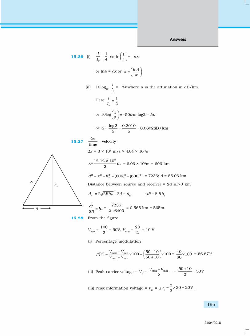
195
Answers
15.26 (i)14o
I
I= , so ln
1 –4
xα =
or ln4 = ax or 4lnx
α
=
(ii) 10log10 –o
Ix
Iα= where α is the attunation in dB/km.
Here 12o
I
I=
or 10log 1 –50 or log2 = 52
α α =
or log2 0.3010
0.0602 B/km5 5
dα = = =
15.272
velocitytime
x=
2x = 3 × 10⁸ m/s × 4.04 × 10⁻³s
512.12 × 10= m
2x = 6.06 × 10⁵m = 606 km
2 2 2 2 2– (606) – (600)sd x h= = = 7236; d = 85.06 km
Distance between source and receiver = 2d ≅170 km
2 2m Td Rh= , 2d = dm, 4d2 = 8 RhT
2
2 T
dh
R= =
72362 6400×
≈ 0.565 km = 565m.
15.28 From the figure
Vmax
= 100
2 = 50V, V
min =
202
= 10 V.
(i) Percentage modulation
max min
max min
– 50 –10(%) 100 100
50 10
V V
V Vµ
= × = × + +
= 40100
60× = 66.67%
(ii) Peak carrier voltage = Vc = max min
2V V+
= 50 10
30V2+
=
(iii) Peak information voltage = Vm = µVc
230 20V
3= × = .
xhs
d
21/04/2018

Exemplar Problems–Physics
196
1mω2mω
1 2m mω ω+
2–c mω ω
2 1–m mω ω 1c mω ω+
cω2c mω ω+
1–c mω ω
15.29 (a) 1 21 2( )= A(A sin sin sin )m m m m c cv t t A t A tω ω ω+ +
1 1 2 2
2( sin sin sin )m m m m c cB A t A t A tω ω ω+ + +
2 21 1= ( sin sin sin )m m m m c cA A t A t A tω ω ω+ +
1 1 2
1 2
2 2 2
1
(( sin ) sin
2 ( sin )
ω ω
ω ω
+ + +
+ +
m m m c c
c m m m c
B A t A t A t
A A t A sin t
1 1 2 2
1 1 2 2 1 2 1 2
1 1 2 2
2 2 2 2
2 2
( sin sin sin )
[ sin 2 sin sin
sin 2 ( sin sin sin ]
m m m c c
m m m m m m m m
c c c m m c m m c
A A t A t A t
B A t A sin t A A t t
A t A A sin t t A t
ω ω ω
ω ω ω ω
ω ω ω ω ω
= + +
+ + +
+ + + +
21 1 2
2 21
1 22 1 1 2
2 2 2 2 2 21
( sin sin sin )
[ sin sin
2[cos( – ) – cos( ) ]
2
m m m m c c
m m m m c c
m m
m m m m
A A t A t A t
B A t A sin t A t
A At t
ω ω ω
ω ω ω
ω ω ω ω
= + +
+ + +
+ +
21 1
2[cos( – ) – cos( ) ]
2c m
c m c m
A At tω ω ω ω+ +
12 2
2[cos( – ) – cos( ) ]
2c m
c m c m
A At tω ω ω ω+ +
∴ Frequencies present are
1 2, ,ω ω ωm m c
2 1 1 2( – ),( )m m m mω ω ω ω+
1 1( – ),( )c m c mω ω ω ω+
2 2( – ),( )c m c mω ω ω ω+
(i) Plot of amplitude versus ω is shown in the Figure.
(ii) As can be seen frequency spectrum is not symmetrical aboutωc. Crowding of spectrum is present for ω < ωc.
21/04/2018

197
Answers
(iii) Adding more modulating signals lead to more crowding in ω < ωc
and more chances of mixing of signals.
(iv) Increase band-width and ωc to accommodate more signals. Thisshows that large carrier frequency enables to carry moreinformation (more ωm) and which will in turn increase band-width.
15.30 fm = 1.5kHz, –310.7 10 s
mf= ×
fc = 20MHz, –710.5 10 s
cf= ×
(i) RC = 103 × 10–8 = 10–5 s
So, 1 1
c m
RCf f
<< < is satisfied
So it can be demodulated.
(ii) RC = 104 × 10–8 = 10–4 s.
Here too 1 1
<< <c m
RCf f
.
So this too can be demodulated
(iii) RC = 104 × 10–12 = 10–8 s.
Here 1
c
RCf
> , so this cannot be demodulated.
21/04/2018