chapter nr 110 - wisconsin 110.03 wisconsin administrative code 74 published under s. 35.93, wis....
TRANSCRIPT

73 NR 110.03DEPARTMENT OF NATURAL RESOURCES
Published under s. 35.93, Wis. Stats., by the Legislative Reference Bureau.
Published under s. 35.93, Stats. Updated on the first day of each month. Entire code is always current. The Register date on each
page is the date the chapter was last published. Register April 2017 No. 736
Chapter NR 110
SEWERAGE SYSTEMS
NR 110.01 Applicability.NR 110.03 Definitions.NR 110.04 Alternative requirements.NR 110.05 Sewer extensions.NR 110.06 Construction plans for reviewable projects.NR 110.07 Specifications for reviewable projects.NR 110.08 Facilities plans for reviewable projects.NR 110.09 Sewage treatment facilities projects.NR 110.10 Sewage collection system projects.NR 110.11 Sewage lift stations.NR 110.12 Owner approval requirement.NR 110.13 Sewer design criteria.NR 110.14 Sewage lift stations design criteria.NR 110.15 General requirements for sewage treatment facilities.
NR 110.16 Screening devices.NR 110.17 Grit removal facilities.NR 110.18 Settling tanks.NR 110.19 Trickling filters.NR 110.20 Rotating biological contactors.NR 110.21 Activated sludge.NR 110.22 Physical−chemical treatment.NR 110.23 Disinfection.NR 110.24 Lagoons.NR 110.25 General conditions required for all land disposal systems.NR 110.255 Conditions required for specific types of land disposal systems.NR 110.26 Sludge handling, storage and disposal.NR 110.27 Requirements for certified or registered laboratory.
History: Chapter NR 110 as it existed on November 30, 1974 was repealed anda new chapter NR 110 was created effective December 1, 1974.
NR 110.01 Applicability. This chapter is applicable to allnew or modified sewerage systems, excluding only industrialwaste treatment facilities. This chapter also applies to seweragesystems employing land disposal of sewage effluent, except thosesystems defined as plumbing within the purview of s. 145.01 (10)(a) 2., Stats.
Note: The authority to enact these rules is contained in ch. 281, Stats. Pursuantto s. 299.97, Stats., any person who violates this chapter shall forfeit not less than $10nor more than $5,000 for each violation. Each day of continued violation is a separateoffense.
History: Cr. Register, November, 1974, No. 227, eff. 12−1−74; correction wasmade under s. 13.93 (2m) (b) 7., Stats., Register, May, 2001, No. 545; correctionmade under s. 13.92 (4) (b) 7., Stats., Register July 2010 No. 655, eff. 8−1−10.
NR 110.03 Definitions. For purposes of this chapter:
(1) “Approved areawide waste treatment management plan”means a plan or element thereof developed pursuant to Section208 of the Federal Water Pollution Control Act Amendments of1972 as amended by the Clean Water Act Amendments of 1977(33 USC 1251 et seq.) and approved by the state of Wisconsin.
(2) “Approval” means the written approval of the departmentfor any project requiring approval pursuant to s. 281.41, Stats.,and s. NR 108.03.
(4) “ASTM” means standards developed by ASTM Interna-tional, 100 Barr Harbor Drive, P.O. Box C700, West Consho-hocken, PA 19428−2959.
Note: Copies of ASTM standards referenced in this chapter are available forinspection at the office of the department of natural resources, the secretary of state’soffice, and the legislative reference bureau, and may be obtained for personal usefrom ASTM International, 100 Barr Harbor Drive, P.O. Box C700, West Consho-hocken, PA 19428−2959.
(6) “AWWA” means the American Water Works Association,6666 West Quincy Avenue, Denver, CO 80235.
Note: Copies of AWWA standards referenced in this chapter are available forinspection at the offices of the department of natural resources, the secretary ofstate’s offices, and the legislative reference bureau, and may be obtained for per-sonal use from the American Water Works Association, 6666 West Quincy Avenue,Denver, CO 80235.
(6e) “Bedrock” means the rocks that underlie soil material orwhere weathered in−place consolidated material larger than 2 mil-limeters in size is greater than 50% by volume.
(6m) “Blending” has the meaning specified under s. NR210.03 (2e).
Note: Section NR 210.03 (2e) reads: “Blending” means the routing of untreatedor partially treated wastewater around a biological treatment process, or a portion ofa biological treatment process, within a sewage treatment facility. The routing ofuntreated or partially treated wastewater around a portion of a biological treatmentprocess is considered to be blending only if the entire wastewater flow has notreceived biological treatment.
(6s) “Building sewer” means that part of the drain system notwithin or under a building which conveys its discharge to a publicsewer, private interceptor main sewer, private onsite wastewatertreatment system, or other point of discharge or dispersal.
Note: This is the same definition as contained in s. SPS 381.01 (44). A buildingsewer may also be referred to as a building lateral.
(7) “Bypass” has the meaning specified in s. NR 205.03 (5).Note: Section NR 205.03 (5) reads: “Bypass” means the intentional diversion of
waste streams from any portion of a sewage treatment facility or a wastewater treat-ment facility. A bypass does not include a building back−up or a combined seweroverflow.
(7e) “Combined sewer overflow” has the meaning specifiedunder s. NR 210.03 (3h).
Note: Section NR 210.03 (3h) reads: “Combined sewer overflow” means arelease of wastewater from a combined sewer system directly into a water of the stateor to the land surface.
(7m) “Combined sewer system” has the meaning specifiedunder s. NR 210.03 (3p).
Note: Section NR 210.03 (3p) reads: “Combined sewer system” means a waste-water collection system owned by a municipality that conveys domestic, commercial,and industrial wastewater and storm water runoff through a single pipe system to apublicly owned treatment works.
(7s) “Combined sewer treatment facility” means all the struc-tures, pipes and other equipment that constitute the various treat-ment processes and treatment units employed to reduce pollutantsin wastewater from combined sewer systems.
(9) “Controlled diversion” has the meaning specified under s.NR 205.03 (9m).
Note: Section NR 205.03 (9m) and Note reads: “Controlled diversion” means therouting of untreated or partially treated wastewater around any treatment unit withina sewage or wastewater treatment facility which is then recombined with undivertedwastewater prior to the effluent sampling location and prior to effluent discharge.
Note: Controlled diversions at a sewage treatment facility do not include blendingand may occur only in compliance with s. NR 205.07 (1) (v).
(11) “Cost−effective analysis” means a systematic compari-son of alternative means of meeting state water quality standards,effluent limitations or other treatment standards in order to iden-tify the alternative which will minimize the total resources costsover the planning period. These resources costs include monetarycosts and environmental as well as other non−monetary costs.
(12) “Department” means the department of naturalresources.
(12g) “Design flow” means the anticipated wastewater dis-charge rate to a sewerage system component, which is used todesign the sewerage system component to provide compliancewith WPDES permit limits and other performance objectives,during the most critical operating conditions anticipated withinthe design planning period. Specific design flow terms used inthis chapter, include the following:

74 NR 110.03 WISCONSIN ADMINISTRATIVE CODE
Published under s. 35.93, Wis. Stats., by the Legislative Reference Bureau.
Published under s. 35.93, Stats. Updated on the first day of each month. Entire code is always current. The Register date on each
page is the date the chapter was last published.Register April 2017 No. 736
(a) “Average daily base flow” means the average of the dailyflow volumes anticipated to occur for a continuous 12−monthperiod, less infiltration and inflow, and expressed as a daily aver-age.
(b) “Average design flow” means the average of the daily flowvolumes anticipated to occur for a continuous 12−month period,expressed as a daily average.
(c) “Maximum month design flow” means the largest volumeof flow anticipated to occur during a continuous 30−day period,expressed as a daily average.
(d) “Maximum week design flow” means the largest volumeof flow anticipated to occur during a continuous 7−day period,expressed as a daily average.
(e) “Maximum day design flow” means the largest volume offlow anticipated to occur during a one−day period, expressed asa daily average.
(f) “Maximum hour design flow” means the largest volume offlow anticipated to occur during a one−hour period, expressed asa daily or hourly average.
(g) “Peak instantaneous design flow” means the maximumanticipated instantaneous flow.
(h) “Peak design flow” and “maximum design flow” mean thelargest volume of flow anticipated to occur on an infrequent basis,expressed as a daily average. The “peak design flow” or “maxi-mum design flow” may be equal to any one of the design flowsdefined in pars. (c) to (g).
(12m) “Design management zone” or “DMZ” means a3−dimensional area, bounded by a set horizontal distance from theapplication or containment area, as specified in Table 4, ch. NR140, and by variable vertical distance which extends from the landsurface downward through all saturated formations.
Note: The size of the DMZ may be altered by the department based on the criteriain s. NR 140.22 (3).
(13) “Dry land access” means a sewage treatment facility ser-vice road which has a minimum elevation of at least one footabove the regional flood elevation.
(13c) “Excessive infiltration/inflow” means the quantities ofinfiltration/inflow which can be economically eliminated from asewerage system by rehabilitation, as determined in a cost−effec-tiveness analysis that compares the cost of correcting the infiltra-tion/inflow conditions to the total costs for transportation andtreatment of the infiltration/inflow.
(13e) “High groundwater level” means the higher of eitherthe elevation to which the soil is saturated as observed as a freewater surface in an unlined hole or the elevation to which the soilhas been seasonally or periodically saturated as indicated by soilcolor patterns throughout the soil profile.
(13t) “Highest anticipated groundwater elevation” means thesum of the calculated mounding effects of the disposal dischargeand the seasonal high groundwater level.
(14e) “Hydraulic application rate” means the average dailyvolume of effluent discharged to a designed acreage of the landapplication system during a calendar month or other period oftime specified in a WPDES permit. The rate is calculated bydividing the total discharge volume for the month or period of timeby the acreage of land and by the number of days in the month orperiod of time, usually expressed in units of gallons per acre perday. For overland flow systems, the hydraulic application rate isexpressed as a flow rate per unit width of slope per day.
(14t) “Hydrogeologist” means a person who is a graduate ofan accredited institution of higher education and who has success-fully completed 30 semester hours or 45 quarter hours of coursework in geology. At least 6 semester hours or 9 quarter hours ofthe geology course work must be in hydrogeology, geohydrologyor groundwater geology. This person shall also have acquiredthrough education and actual field experience the ability to directthe drilling of borings, and the installation and development of
wells; describe and classify geology samples and evaluate andinterpret geologic and hydrogeologic data in accordance with therequirements of chs. NR 110 and 206.
(15) “Industrial user” means:
(a) Any nongovernmental, nonresidential user of a munici-pally owned sewerage system which discharges more than theequivalent of 25,000 gallons per day (gpd) of sanitary wastes andwhich is identified in the Standard Industrial Classification Man-ual, 1972, United States Office Management and Budget, asamended and supplemented as of October 1, 1978 under one of thefollowing divisions:
Division A. Agriculture, Forestry, and FishingDivision B. MiningDivision D. ManufacturingDivision E. Transportation, Communications, Electric,
Gas, and Sanitary ServicesDivision I. Services.
1. In determining the amount of a user’s discharge, domesticwastes or discharges from sanitary conveniences may beexcluded.
2. After applying the sanitary waste exclusion in subd. 1., dis-charges in the above divisions that have a volume exceeding25,000 gpd or the weight of biochemical oxygen demand (BOD)or suspended solids (SS) equivalent to that weight found in 25,000gpd of sanitary waste are considered industrial users. Sanitarywastes, for purposes of this calculation of equivalency, are thewastes discharged from residential users. The municipality shall,with the department’s approval, define the strength of the residen-tial waste discharges in terms of parameters including biochemi-cal oxygen demand (BOD) and suspended solids (SS) per volumeof flow as a minimum. Dischargers with a volume exceeding25,000 gpd or the weight of BOD or SS equivalent to that weightfound in 25,000 gpd of sanitary waste are considered as industrialusers.
(b) Any nongovernmental user of a municipally owned sewer-age system which discharges wastewater to the sewerage systemwhich contains toxic pollutants or poisonous solids, liquids, orgases in sufficient quantity either singly or by interaction withother wastes, to contaminate the sludge of any municipal system,or injure or interfere with any sewage treatment process, consti-tutes a hazard to humans or animals, creates a public nuisance, orcreates any hazard in or has an adverse effect on the waters receiv-ing any discharge from the treatment works;
(c) All commercial users of an individual system constructedwith grant assistance under s. 281.57, Stats.
(16) “Infiltration” means water other than wastewater thatenters a sewerage system (including sewer service connections)from the ground through such sources as defective pipes, pipejoints, connections, or manholes. Infiltration does not include,and is distinguished from, inflow.
(17) “Inflow” means water other than wastewater that entersa sewerage system (including sewer service connections) fromsources such as roof leaders, cellar drains, yard drains, area drains,foundation drains, sump pumps, drains from springs and swampyareas, manhole covers, cross connections between storm sewersand sanitary sewers, catch basins, cooling towers, storm waters,surface runoff, street wash waters, or drainage. Inflow does notinclude, and is distinguished from, infiltration.
(18) “Interceptor sewer” means a sewer whose primary pur-pose is to transport wastewaters from collector sewers to a treat-ment facility.
(18m) “Intermediate sludge storage” means the storage ofsludge for a period of more than 24 hours and no more than 3months.
(19) “Lagoon” means those sewage treatment facilities wherethe wastewater or sludge containment structure is constructed pri-marily of earthen materials.

75 NR 110.04DEPARTMENT OF NATURAL RESOURCES
Published under s. 35.93, Wis. Stats., by the Legislative Reference Bureau.
Published under s. 35.93, Stats. Updated on the first day of each month. Entire code is always current. The Register date on each
page is the date the chapter was last published. Register April 2017 No. 736
(19m) “Long−term sludge storage” means the storage ofsludge for a period exceeding 3 months.
(21) “Municipality” means any city, town, village, county,utility district, town sanitary district, public inland lake protectionand rehabilitation district or metropolitan sewage district.
(22) “NEC” means the NFPA 70 National Electrical Code.Copies of the National Electrical Code are available for inspectionat the offices of the department of natural resources, the secretaryof state’s office, and the legislative reference bureau. Copies maybe obtained for personal use from the National Fire ProtectionAssociation, 1 Batterymarch Park, Quincy, MA 02169−7471.
(23) “Owner” means the state, county, town, town sanitarydistrict, city, village, firm, company, institution, association, util-ity district, school district, metropolitan sewerage district, or indi-vidual owning or operating a sewerage system.
(25) “Planning area” means that area under study as part of afacilities plan.
(26) “Planning period” means the period over which sewer-age system alternatives are evaluated for cost−effectiveness. Theplanning period begins with the initiation of the operation of theproposed facilities.
(26m) “Private interceptor main sewer” means a sewer serv-ing two or more buildings and not part of the municipal sewer sys-tem.
Note: This is the same definition as contained in s. SPS 381.01 (193).
(27) “Reviewable project” means any construction or instal-lation project for which department approval is required, pursuantto s. 281.41, Stats., including any new sewerage system; and, anyimprovements, extensions, or alterations of existing seweragesystems which may effect the quality or quantity of effluent or thelocation of any outfall.
(27e) “Sanitary sewer overflow” has the meaning specifiedunder s. NR 210.03 (10).
Note: Section NR 210.03 (10) reads: “Sanitary sewer overflow” means a releaseof wastewater from a sewage collection system or an interceptor sewer directly intoa water of the state or to the land surface.
(27m) “Sanitary sewer overflow structure” means the physi-cal structure, hydraulic mechanisms, and piping specifically con-structed to convey a sanitary sewer overflow.
(27s) “Satellite sewage collection system” has the meaningspecified under s. NR 205.03 (31r).
Note: Section NR 205.03 (31r) reads: “Satellite sewage collection system” meansa municipally owned or a privately owned sewage collection system that conveyswastewater to another satellite sewage collection system or to another sewerage sys-tem that provides wastewater treatment and discharges under a separate WPDES per-mit.
(28) “Sewage collection system” means the common sanitarysewers, interceptor sewers, and appurtenant equipment, such aslift stations, within a sewerage system which are primarilyinstalled to receive wastewaters directly from facilities whichconvey wastewater from individual structures or from privateproperty, and which include service connection “Y” fittingsdesigned for connection with those facilities. The facilities whichconvey wastewater from individual structures, such as buildingsewers and private interceptor sewers, from private property to thepublic sanitary sewer, or its equivalent, are specifically excludedfrom the definition of “sewage collection system”; except thatpumping units and pressurized lines for individual structures orgroups of structures are included as part of a “sewage collectionsystem” when such units are cost effective and are owned andmaintained by the sewerage system owner.
(29) “Sewage treatment facility” means all the structures,pipes, and other equipment that constitute the various treatmentprocesses and treatment units employed to reduce pollutants insewage.
(29d) “Sewage treatment facility overflow” has the meaningspecified under s. NR 210.03 (13).
Note: Section NR 210.03 (13) reads: “Sewage treatment facility overflow” meansa release of wastewater from a location within a sewage treatment facility, other than
permitted effluent outfall structures, directly to a water of the state or to the land sur-face. A sewage treatment facility overflow does not include blending, controlleddiversions or discharges from permitted combined sewage treatment facility effluentoutfall structures.
(29h) “Sewage treatment facility overflow structure” meansthe physical structure, hydraulic mechanisms, and piping specifi-cally constructed to convey a sewage treatment facility overflow.
(29m) “Sewer extension” means installation of a sewer orinterceptor sewer, or extension thereof, to provide additional con-veyance capacity and service to development within the existingor proposed tributary area of the extension. Alterations or modifi-cations of existing sewerage systems designed to replace inade-quate existing structures or installed because of inadequatehydraulic sewer capacity and that do not extend sanitary sewerservice to areas previously not served are not sewer extensions.
(29t) “Sewer service area” means that area served or antici-pated to be served by a sewage collection system.
(30) “Sewerage system” means all structures, conduits andpipes, by which sewage is collected, treated, and disposed of,except plumbing inside and in connection with buildings served,and service pipes, from building to street main.
(31c) “Short−term sludge storage” means the storage ofsludge for a period of no more than 24 hours.
(31e) “Sludge storage” means the retention of sludge at atreatment plant or at an approved off−site facility.
(32) “Staging period” means the period of time during whichreserve capacity will be provided in the sewerage system forfuture domestic, commercial, and industrial flows.
(32g) “Treatment process” means a physical, biological orchemical action that is applied to wastewater to remove or reducepollutants. A treatment process may consist of multiple individ-ual treatment units. “Treatment process” includes screening,chemical treatment, sedimentation, biological treatment, filtra-tion, disinfection, and sludge digestion.
(32i) “Treatment unit” means individual structures or equip-ment within a sewage or wastewater treatment facility that are partof a treatment process. Typical treatment units are screens, clarifi-ers, aeration tanks, filters, digesters, and lagoons.
(32m) “Water table observation well” means any groundwa-ter monitoring well whose screen intersects the water, which isinstalled for the specific purpose of determining either the eleva-tion of the water table or the physical, chemical, biological, orradiological properties of groundwater at the water table, or both.
(34) “WPDES permit” means the Wisconsin pollutant dis-charge elimination system permit issued by the department underch. 283, Stats., for the discharge of pollutants.
History: Cr. Register, November, 1974, No. 227, eff. 12−1−74; r. and recr. Regis-ter, December, 1978, No. 276, eff. 1−1−79; cr. (20), Register, August, 1981, No. 308,eff. 9−1−81; renum. (3) to (20) to be (11), (12), (14) to (18), (21), (23), (25) to (32)and (34) and am. (29) and (34), cr. (4) to (10), (13), (19), (20), (22), (24) and (33),Register, February, 1983, No. 326, eff. 3−1−83; cr. (6m), (12m), (13e), (13t), (14e),(14t), (18m), (19m), (31e), (31t) and (32m), am. (19), Register, November, 1990, No.419, eff. 12−1−90; corrections in (2), (27), and (34) were made under s. 13.93 (2m)(b) 7., Stats., Register, May, 2001, No. 545; corrections in (3), (4), (6), (22) and (33)made under s. 13.92 (4) (b) 6., Stats., Register February 2010 No. 650; CR 09−123:r. (3), (5), (20), (24) and (33), r. and recr. (4) and (6), am. (9) and (22), cr. (12g) Regis-ter July 2010 No. 655, eff. 8−1−10; CR 12−027: renum. (6m) to (6e), cr. (6m), (6s),r. and recr. (7), cr. (7e), (7m), (7s), r. (8), r. and recr. (9), r. (10), am. (17), cr. (26m),(27e), (27m), (27s), am. (28), r. and recr. (29), cr. (29d), (29h), (30p), renum. (31) to(29t), cr. (32g), (32r) Register July 2013 No. 691, eff. 8−1−13; renum. (14), (30p),(31t), (32r) to (13c), (29m), (31c), (32i) under s. 13.92 (4) (b) 1., Stats., Register July2013 No. 691; correction in (15) (c) made under s. 13.92 (4) (b) 7., Stats., RegisterApril 2017 No. 736.
NR 110.04 Alternative requirements. (1) If the ownerof a proposed reviewable project feels that compliance with thedesign requirements of this chapter is impracticable, the reasonstherefor shall be fully communicated in writing to the departmentprior to the submission of final plans. This communication mustset forth alternative requirements for which department approvalis sought and all pertinent facts, data, reports and studies support-ing the imposition of such alternative requirements.

76 NR 110.04 WISCONSIN ADMINISTRATIVE CODE
Published under s. 35.93, Wis. Stats., by the Legislative Reference Bureau.
Published under s. 35.93, Stats. Updated on the first day of each month. Entire code is always current. The Register date on each
page is the date the chapter was last published.Register April 2017 No. 736
(2) If the department determines that compliance with thedesign requirements of this chapter would be impracticable in spe-cific cases, it may approve alternative requirements which, in itsopinion, are in substantial compliance with the requirements ofthis chapter.
History: Cr. Register, November, 1974, No. 227, eff. 12−1−74.
NR 110.05 Sewer extensions. (1) PURPOSE. The pur-pose of this section is to insure that department approval of appli-cations for sanitary sewer extensions are consistent with andenhance the policy of the state to restore and maintain the chemi-cal, physical and biological integrity of its waters to protect publichealth, safeguard fish and aquatic life and scenic and ecologicalvalues and enhance the domestic, municipal, recreational, indus-trial, agricultural and other uses of water.
(3) PERMISSIVE APPROVALS RELATED TO PERMITTED EFFLUENT
LIMITATIONS. (a) Unless an approval would be contrary to the pur-pose of this section, applications for sanitary sewer extensionsthat comply with all applicable requirements of this chapter shallbe approved if the sewer will be tributary to a sewage treatmentfacility in compliance with the monthly average effluent limita-tions for biochemical oxygen demand (BOD) and total suspendedsolids contained in its WPDES permit.
(b) In the event that the WPDES permit for a sewage treatmentfacility currently discharging an effluent in accordance with ch.NR 210 establishes a compliance schedule for achievement of anymore stringent water quality related effluent limitations for bio-chemical oxygen demand and total suspended solids applicable tosuch treatment facility, compliance with the schedule of compli-ance in the discharge permit will be deemed to be compliance withthe applicable water quality related effluent limitations.
(c) In determining whether a discharged effluent is in com-pliance with the monthly average effluent limitations for bio-chemical oxygen demand (BOD) and total suspended solids con-tained in a WPDES permit, the following procedure shall apply:
1. Compliance shall be determined by department review ofthe previous 12 months of discharge monitoring data. If 12months of data are not available, the review shall be based on thedata that are available.
2. More than a total of 3 months of violations of the monthlyaverage limitations for either BOD or total suspended solids orboth in the previous 12 months (or the equivalent ratio for thenumber of months of data available) shall cause denial, subject tothe following additional considerations:
a. Recognition of the inherent inaccuracy of the BOD andtotal suspended solids tests shall be given by multiplying themonthly average effluent limitations as specified in the permit bya factor of 1.3 for BOD and 1.2 for total suspended solids for pur-poses of determining whether monthly average effluent results arein compliance.
b. The department may grant approval if it determines that,due to a demonstrable action by the permittee, the sewage treat-ment facility has been in compliance for four or more consecutivemonths, thus demonstrating a trend toward better operation.
c. The department may grant approval in those instanceswhere the permittee demonstrates that noncompliance with theeffluent limitations has been caused by algae growth in a sewagetreatment facility utilizing lagoons as the principal treatment pro-cess.
d. The department may grant approval if it determines thatnoncompliance with the effluent limitations has been caused byoperating difficulties associated with startup for those sewagetreatment facilities which have recently been constructed orundergone major modification or expansion. The perioddescribed as startup may be no longer than 12 consecutivemonths.
(4) DENIAL RELATED TO PERMITTED EFFLUENT LIMITATIONS. (a)Taking into account the factors in sub. (3) (c), applications for san-
itary sewer extensions shall be denied if the sewer will be tributaryto a sewage treatment facility not in compliance with the monthlyaverage effluent limitations for biochemical oxygen demand(BOD5) and total suspended solids contained in its WPDES per-mit.
(b) If the WPDES permit for a sewage treatment facility estab-lishes a compliance schedule for achievement of any more strin-gent water quality related effluent limitations for biochemicaloxygen demand and total suspended solids applicable to suchtreatment plant, compliance with the schedule of compliance inthe discharge permit shall be deemed to be compliance with theapplicable water quality related effluent limitations.
(5) EXCEPTIONS. Sewer extensions otherwise prohibited bysub. (4) may be granted by the department upon the determinationof any of the following:
(a) That construction of the subdivision, commercial estab-lishment, institutional facility or industrial plant had commencedprior to May 24, 1976, as evidenced by the issuance of a buildingpermit;
(b) That the area to be served was developed prior to May 24,1976, and that the sewer extension will eliminate use of existingprivate sewage systems which pose a threat to the public health orsafety, provided that connections to the sewer are allowed only forthe existing development;
(d) That the proposed extension is a modification of a sewerextension previously approved by the department, providing thatthe modification results in no increase in the anticipated waste dis-charge to the sewer system;
(e) That the facilities to be served are intended primarily to pro-vide educational, humanitarian, or charitable community ser-vices;
(f) That the program, time schedule, and the commitment toproceed are established in a court−approved stipulation, order, orjudgment.
(6) CONNECTION RESTRICTIONS. As a condition of anyapproval granted under sub. (5), the department may require thatan applicant for a sewer extension restrict the number of con-nections made to the sewer system in accordance with a pre-scribed schedule.
History: Cr. Register, November, 1974, No. 227, eff. 12−1−74; emerg. r. and recr.eff. 5−24−76; r. and recr. Register, September, 1976, No. 249, eff. 10−1−76; am. (3)(b) and (4) (b), Register, April, 1980, No. 292, eff. 5−1−80; am. Register, August,1981, No. 308, eff. 9−1−81; am. (4), r. (7), renum. (8) to be (7), Register, June, 1982,No. 318, eff. 7−1−82; emerg. cr. (5) (g), eff. 4−15−83; cr. (5) (g) Register, September,1983, No. 333, eff. 10−1−83; corrections in (2) (c) and (g) were made under s. 13.93(2m) (b) 7., Stats., Register, May, 2001, No. 545; CR 09−123: am. (2) (c), (5) (c) and(6), r. and recr. (4), r. (5) (g) Register July 2010 No. 655, eff. 8−1−10; CR 12−027:r. (2), am. (3), (4), r. (5) (c), r. (7) Register July 2013 No. 691, eff. 8−1−13.
NR 110.06 Construction plans for reviewable proj-ects. (1) All construction plans for reviewable projects sub-mitted to the department shall be in conformance with ch. NR 108,and shall bear a suitable title block which includes the name of theowner, the scale and the date. The north point shall be shown oneach plan. All plans shall be clear and legible. Blueprints will notbe accepted. The datum used shall be indicated and shall berelated to U.S.G.S. datum.
(2) Detailed construction plans shall contain appropriate planviews, elevations, necessary sections and supplemental viewswhich together with the specifications provide all necessary infor-mation for construction of the project. Manufacturers’ drawingsshall not be accepted.
(3) All construction plans shall be in conformance with anapproved facilities plan as required in s. NR 110.08 (1).
(4) If the construction of a proposed project requires, or mayrequire, any permit under s. 30.12, 30.19, 30.195, or 30.20, Stats.,application for the necessary permits shall be made to the depart-ment at the same time the project plans and specifications are sub-mitted for review. Failure to apply for the necessary permits shallbe cause for denial or rejection of the plans and specifications.
77 NR 110.08DEPARTMENT OF NATURAL RESOURCES
Published under s. 35.93, Wis. Stats., by the Legislative Reference Bureau.
Published under s. 35.93, Stats. Updated on the first day of each month. Entire code is always current. The Register date on each
page is the date the chapter was last published. Register April 2017 No. 736
Note: Applicable state and local codes, including those of the department of indus-try, labor and human relations, the public service commission and the department ofhealth and social services, should be consulted for other requirements.
History: Cr. Register, November, 1974, No. 227, eff. 12−1−74; r. and recr. Regis-ter, December, 1978, No. 276, eff. 1−1−79; cr. (4), Register, February, 1983, No. 326,eff. 3−1−83.
NR 110.07 Specifications for reviewable projects.(1) Complete technical specifications for all reviewable projectsshall accompany the construction plans. Where feasible the speci-fications shall contain provisions for maintaining the same degreeof wastewater treatment during construction as that which existedprior to the start of construction.
(2) The specifications accompanying the detailed construc-tion drawing shall include, wherever applicable:
(a) All construction information not shown on the plans;
(b) The complete requirements for all mechanical and electri-cal equipment;
(c) The type and operating characteristics of all equipment;
(d) The laboratory fixtures and equipment;
(e) The construction materials to be used;
(f) The identification of the chemicals to be used; and
(g) The instructions for testing materials and equipment tomeet design standards.
(3) Specifications reproduced from manufacturers’ data andbearing the manufacturers’ labels will not be accepted.
History: Cr. Register, November, 1974, No. 227, eff. 12−1−74; r. and recr. Regis-ter, December, 1978, No. 276, eff. 1−1−79.
NR 110.08 Facilities plans for reviewable projects.(1) APPLICABILITY. A facilities plan shall be prepared for eachreviewable project submitted to the department for approval.Facilities plans for sewage treatment facilities or new sewage col-lection systems shall be submitted to and approved by the depart-ment prior to submittal of the construction plans and speci-fications. The department may accept construction plans andspecifications for review prior to facilities plan approval providedthat all substantive issues of the facilities plan review have beenresolved.
(2) CONTENT. The facilities plan for municipally owned sew-age treatment facilities, sewage collection systems, and intercep-tors shall contain all of the information required by s. NR 110.09(1) through (6), 110.10 (1) and (2), or 110.11 (1), whichever areapplicable. The following facilities planning requirements do notapply to nonmunicipally owned facilities: s. NR 110.09 (1) (b) 3.,5. and 8., and (2) (b) to (e) and (j) to (m). The level of detail neces-sary to fulfill the requirements of this subsection may varydepending on the size and complexity of the project.
(3) WISCONSIN ENVIRONMENTAL POLICY ACT REVIEW. Facilitiesplans shall be reviewed by the department in accordance with ch.NR 150.
(4) CONFORMANCE WITH APPROVED AREAWIDE WASTE TREAT-MENT MANAGEMENT PLANS. All approvable sewerage system facil-ity plans must be in conformance with approved areawide wastetreatment management plans unless the department determinesthat such plans conflict with the department’s responsibilities toprotect, maintain, and improve the quality and management of thewaters of the state, ground and surface, public and private. In theabsence of an approved areawide waste treatment managementplan, no determination of such conformance is required.
(5) APPROVAL OF NEW SEWAGE TREATMENT FACILITIES. It is thepolicy of the department to restrict the construction of new sewagetreatment facilities in order to preserve and protect the quality ofthe waters of the state. The department may deny requests forapproval of new sewage treatment facilities unless they meet thefollowing criteria:
(a) Treatment facilities to serve existing residential develop-ment. Proposals for new treatment facilities to serve existing resi-dential development may not be approved unless:
1. They are necessary to solve a documented and severe exist-ing water quality (groundwater or surface water) or public healthproblem related to inadequate existing residential sewage dis-posal; or, are needed to replace an existing treatment facilitywhich is not in compliance with its WPDES permit;
2. They are the cost−effective alternative solution in accord-ance with s. NR 110.09 (1) (a); and
3. They are municipally owned, operated and maintained.
(b) Interim treatment facilities. An interim treatment facilityis one which would serve areas which are within the future sewerservice area of another existing facility as delineated in anapproved areawide water quality management plan as providedfor in ch. NR 121. Proposals for new interim treatment facilitiesmay not be approved unless:
1. They are necessary to solve a documented and severe exist-ing water quality (groundwater or surface water) or public healthproblem related to inadequate existing residential sewage dis-posal; or, are needed to replace an existing treatment facilitywhich is not in compliance with its WPDES permit;
2. They are the cost−effective alternative solution in accord-ance with s. NR 110.09 (1) (a);
3. They are municipally owned, operated and maintained;
4. The sewage collection system is designed so that it can beeasily connected to the regional system in the future;
5. The sewer service area of the proposed system lies entirelywithin the planned service area of the regional system as delin-eated in an approved areawide water quality management plan;and
6. An agreement is signed by all involved municipalitieswhich provides for a specified date of abandonment and connec-tion. This intermunicipal agreement may be reviewed andapproved by the department prior to facilities plan approval. TheWPDES permits may contain schedules for facilities abandon-ment and connection.
(c) Treatment facilities serving isolated nonresidential devel-opment. Nonresidential development includes things such asparks and recreational facilities, airports, highway oriented com-mercial facilities and institutions such as hospitals, nursinghomes, prisons and schools. Proposals for new treatment facilitiesto serve nonresidential development may not be approved unless:
1. Joint treatment with other wastewater treatment systems isnot feasible;
2. The proposed facilities are designed to treat only wastesgenerated by the proposed nonresidential development; and
3. The WPDES permit limits service to the proposed nonresi-dential development.
(d) Treatment facilities to serve new residential development.Proposals for new treatment facilities intended to serve new resi-dential development such as facilities for residential subdivisions,mobile home parks and condominium developments may bedenied.
(dg) Variances. Variances to this general prohibition may begranted:
1. Only after the department has considered:
a. The general public interest;
b. Environmental impacts;
c. Socioeconomic impacts; and
d. The impact on orderly development and provision of gen-eral governmental services within the service area; and
2. Only after a finding that all of the following criteria are met:
a. The proposal is consistent with the department’s responsi-bility to protect, maintain and improve the quality and manage-ment of the waters of the state;
b. The proposed facilities will be municipally owned, oper-ated and maintained;

78 NR 110.08 WISCONSIN ADMINISTRATIVE CODE
Published under s. 35.93, Wis. Stats., by the Legislative Reference Bureau.
Published under s. 35.93, Stats. Updated on the first day of each month. Entire code is always current. The Register date on each
page is the date the chapter was last published.Register April 2017 No. 736
c. The proposed facilities will be more cost−effective inaccordance with s. NR 110.09 (1) (a) than other treatment and dis-charge alternatives; and
d. All other federal, state and local approvals and permitshave been obtained.
(dm) Treatment facilities to serve existing mobile home parksand condominium developments. Proposals for new treatmentfacilities to serve existing residential developments at mobilehome parks and condominium developments may not beapproved unless:
1. The conditions of par. (a) are met; or
2. The conditions of par. (a) 1. and 2. are met and the ownersubmits the following:
a. Adequate proof that sufficient funds to operate, maintainand abandon the facility, if necessary, will be available for the lifeof the facility;
b. Documentation showing that the new treatment facilitiesare being proposed as a replacement of a failing septic tank/soilabsorption system which has been in use for at least 10 years; and
c. Proof of the inability to form a town sanitary district orother appropriate municipal entity to oversee the facility.
(e) Conformance with areawide water quality managementplans. In addition to the requirements of pars. (a) through (dg), thenew sewage treatment facilities shall also be in conformance withany approved areawide water quality management plan. Theseplans may be consistent with the criteria in pars. (a) through (dg).These plans as approved by the department may also contain addi-tional criteria necessary to address regional or local consider-ations.
(6) COST EFFECTIVENESS. A cost−effectiveness analysis shallbe performed as part of the evaluation of alternatives in each facil-ities plan. The cost−effectiveness analysis shall be prepared inaccordance with s. NR 110.09 (2). Except as provided for in s. NR110.09 (2) (j) 4. c., the most cost−effective alternative shall beselected for implementation.
History: Cr. Register, November, 1974, No. 227, eff. 12−1−74; r. and recr. Regis-ter, December, 1978, No. 276, eff. 1−1−79; cr. (5), Register, August, 1981, No. 308,eff. 9−1−81; am. (1) and (2), cr. (6), Register, February, 1983, No. 326. eff. 3−1−83;cr. (5) (dm), Register, November, 1990, No. 419, eff. 12−1−90; correction in (5) madeunder s. 13.93 (2m) (b) 1. and 7., Stats., Register, September, 1995, No. 477; CR09−123: renum. (3) (a) to be (3) and am., r. (3) (b) Register July 2010 No. 655, eff.8−1−10.
NR 110.09 Sewage treatment facilities projects.(1) FACILITIES PLANS FOR SEWAGE TREATMENT FACILITIES PROJ-ECTS. (a) Facilities plans consist of those necessary plans andstudies which directly relate to the construction of the proposedfacilities. Facilities planning shall demonstrate the need for theproposed facilities. Through a systematic evaluation of feasiblealternatives facilities planning shall also demonstrate that theselected alternative is the most cost−effective means of meetingestablished effluent limitations and water quality standards. Themost cost−effective alternative is that which will result in the min-imum total resources costs over the planning period. The plan-ning period of the facilities plan shall be 20 years. The totalresources costs include monetary costs, environmental and socialconsiderations, and other nonmonetary factors. The interest (dis-count) rate to be used in calculating present worth shall beobtained from the department when beginning facilities planning.
(b) Facilities planning shall include the following informationin such detail as the department deems appropriate for the specificproject:
1. A description of the sewerage system for which construc-tion drawings and specifications are to be prepared. This descrip-tion shall include preliminary engineering data, cost estimates fordesign and construction of the sewerage system, and a schedulefor completion of design and construction. The preliminary engi-neering data shall include, to the extent appropriate, informationsuch as a schematic flow diagram, unit processes, design dataregarding detention times, flow rates, sizing of units, and so forth.
This is commonly referred to as the Unit Equipment and DesignReport.
2. A description of the selected complete sewerage system ofwhich the proposed facilities will be a part using maps, diagramsand plans as appropriate. This description shall include:
a. The delineation of a sewer service area for the completesewerage system based on a 20−year population projection anddensity assumptions;
b. A description of the collection system including existingand proposed trunk sewers and interceptors;
c. A description of the existing and proposed sewerage treat-ment system including ultimate disposal of wastewater andsludge;
d. A planning area map showing individual systems, if indi-vidual systems are to be a part of the cost−effective solution pro-posed for state or EPA funding.
3. Infiltration/inflow documentation in accordance with subs.(5) and (6).
4. A cost−effectiveness analysis of alternatives for the sewer-age system prepared in accordance with sub. (2). The most cost−effective alternatives shall be selected for implementation inaccordance with s. NR 110.08 (6).
5. For facilities plans for state funded projects, parallel costestimates shall be provided for the facilities necessary to transportand/or treat the fundable capacity, as well as a cost estimate for thetotal proposed sewerage system.
6. An identification of effluent discharge limitations includ-ing water quality related effluent limitations, and where a Wiscon-sin Pollution Discharge Elimination System (WPDES) permit hasbeen issued, a copy of the permit for the proposed sewerage sys-tem.
7. Required comments or approvals of relevant state, inter-state, regional, and local agencies.
8. An estimate of the anticipated cost to the average user ofthe system. This cost shall be presented at the public hearingrequired under sub. (4).
9. A brief summary of the public hearing required under sub.(4) or any other public meeting or hearing held during the plan-ning process including a summary of the views expressed.
10. A brief statement demonstrating that the authorities whowill be implementing the plan have the necessary legal, financial,institutional, and managerial resources available to insure the con-struction, operation, and maintenance of the proposed treatmentworks.
11. A description of potential opportunities for recreation,open space, and access to bodies of water analyzed in planning theproposed sewerage system and the recommended actions. Thefacility plan shall also describe measures taken to coordinate withfederal, state and local recreational programs and with recre-ational elements of applicable approved areawide waste treatmentmanagement plans.
Note: Facilities plans for projects subject to the requirements of this section mayinclude results from a system evaluation and capacity assurance plan under s. NR110.10 (4).
(2) CONTENT OF THE COST−EFFECTIVENESS ANALYSIS. The cost−effectiveness analysis shall include:
(a) The relationship of the size and capacity of alternative sys-tems to the needs to be served, including reserve capacity;
(b) An evaluation of alternative flow and waste reduction mea-sures, including non−structural methods;
(c) An evaluation of improved effluent quality attainable byupgrading the operation and maintenance and efficiency of exist-ing facilities as an alternative or supplement to construction ofnew facilities;
(d) An evaluation of the capability of each alternative to meetsecondary treatment standards or applicable water quality relatedeffluent limitations. The sewerage system design must be based

79 NR 110.09DEPARTMENT OF NATURAL RESOURCES
Published under s. 35.93, Wis. Stats., by the Legislative Reference Bureau.
Published under s. 35.93, Stats. Updated on the first day of each month. Entire code is always current. The Register date on each
page is the date the chapter was last published. Register April 2017 No. 736
upon achievement of not less than secondary treatment standardsas defined by ch. NR 210;
(e) An identification of and provision for applying technolo-gies included under each of the following waste treatment man-agement techniques:
1. Biological or physical−chemical treatment and dischargeto receiving waters;
2. Systems employing the reuse of wastewater and recyclingof pollutants;
3. Land application techniques;
4. Systems including revenue generating applications; and
5. On−site and non−conventional systems.
(f) All construction of publicly−owned sewerage systems andprivately owned domestic sewerage systems discharging to sur-face waters shall be based upon application of secondary treat-ment as a minimum. Where application of secondary treatmentwould not provide for attainment of water quality standards,thefacilities plan shall provide for attaining the applicable standardsby designing to meet appropriate water quality related effluentlimitations. Sewerage systems discharging to the ground watershall comply with the applicable discharge requirements of ch.NR 206. The alternative of treating combined sewer overflowsshall also be considered.
(g) An evaluation to determine the cost−effective means of dis-posing of treated effluent.
(h) An evaluation of the most cost−effective means of treating,handling, and disposing of sludge. This evaluation shall includeat a minimum the following items:
1. A description of the current sludge treatment, handling anddisposal operations including a discussion of current quantitiesbeing produced, a description of current sludge quality includinga sludge analysis, a description of any problems associated withthe existing operations, and a description of industrial contribu-tions that may affect the quantity and quality of sludge;
2. An analysis of the anticipated quantity and quality of thesludge from the proposed facility;
3. A brief description of alternative technologies applicableto the proposed facility improvements, such as, thickening, stabi-lization, dewatering, storage, transportation, and ultimate dis-posal;
4. A cost−effectiveness analysis of the feasible alternativesincluding an assessment of the environmental impacts as speci-fied in sub. (3);
5. An evaluation of the storage requirements either at the sew-age treatment facility or at an offsite location. The evaluation shallinclude an estimate of the maximum period of time necessary tostore sludge, and a description of the location, accessibility, soils,necessary local permits, depth to groundwater, distance to resi-dential homes, type of facility, topography and any other appropri-ate information. The storage recommendations shall comply withs. NR 110.26 (10).
6. An estimate of the amount of land required for each alterna-tive shall be made. Land requirements for landfilling of sludgeshall be based upon accepted landfill design practices. Depart-ment approval in accordance with chs. NR 500 to 520, is requiredfor construction of sludge landfills and prior to disposal of sludgeat an existing licensed landfill.
7. A discussion of the procedures and timing for abandon-ment of the existing sludge facilities, if appropriate. This shallinclude, but not be limited to, the types of sludge wastes to be dis-posed of during abandonment, ultimate disposal location, pos-sible construction scheduling, quantity of wastes, quality ofwastes and any special problems associated with the disposal ofthese wastes; and
8. A summary describing the selected plan and its anticipatedenvironmental impacts. Those actions necessary for implement-ing and operating the sludge management plan shall be presented.
This shall include, but not be limited to, the estimated sludge treat-ment and disposal costs, operator time, discussion of applicablefederal and state laws, necessary local permits, public participa-tion programs, training of operators and any other actions neces-sary to provide for an environmentally sound sludge managementprogram.
(i) An adequate assessment of the expected environmentalimpacts of the alternatives (including sites) in accordance withsub. (3). This assessment shall be an integral part of the analysisof alternatives for cost−effectiveness. The assessment shall berevised as necessary to include information developed during sub-sequent project steps.
(j) An analysis of the most cost−effective design staging andsizing. The staging and sizing of treatment works shall be basedupon the following:
1. Population projections. Population projections for facili-ties planning shall be in conformance with those contained inapplicable approved areawide waste treatment management plansand rules adopted pursuant to ss. 16.96 and 281.57 (4) (b), Stats.If such projections are not available, the engineer shall projectfuture population growth based on trends in the recent past.
2. Wastewater flow estimates. In determining total averageflow for the design of sewerage systems, the flows to be consid-ered include the average daily base flows (ADBF) expected fromeach of the following: residential sources, commercial sources,institutional sources, and industries the system will serve plusallowances for future industries and nonexcessive infiltration orinflow.
2m. Estimation methods. The estimation of existing andfuture ADBF from combined residential, commercial, and institu-tional sources, shall be based upon one of the following methods:
a. Existing ADBF shall be estimated based upon a fully docu-mented analysis of water use records adjusted for consumptionand losses or on records of wastewater flows for extended dryperiods less estimated dry weather infiltration. Future flows forthe sewerage system design shall be estimated by determining theexisting per capita flows, subtracting any projected per capitawater conservation flow reduction and multiplying this figure bythe future projected population to be served. Seasonal populationcan be converted to equivalent full−time residents using the fol-lowing multipliers:
Day−use visitor (0.1−0.2).
Seasonal visitor (0.5−0.8).
The preferred method shall be used wherever water supplyrecords or wastewater flow data exist. Allowances for futureincreases of per capita flow over time will not be approved.
b. Where water supply and wastewater flow data are lacking,existing and future ADBF shall be estimated by multiplying a gal-lon per capita per day (gpcd) allowance not exceeding those in thefollowing table by the estimated total of the existing and futureresident populations to be served. The tabulated ADBF allow-ances include estimates for commercial and institutional sourcesas well as residential sources. The department may approveexceptions to the tabulated allowances where large commercialand institutional flows (more than 25% of total estimated ADBF)are documented.
Description
Gallons per
capita per
day (gpcd)
Non−SMSA cities and towns with projected total 10−yr population of 5,000 or less . . . 60−70
Other cities and towns . . . . . . . . . . . . . . . . . 65−80
3. Industrial flows. a. The sewerage system total design flowcapacity may include allowances for industrial flows. The allow-ances may include capacity needed for industrial flows which theexisting sewerage system presently serves. However, these flows

80 NR 110.09 WISCONSIN ADMINISTRATIVE CODE
Published under s. 35.93, Wis. Stats., by the Legislative Reference Bureau.
Published under s. 35.93, Stats. Updated on the first day of each month. Entire code is always current. The Register date on each
page is the date the chapter was last published.Register April 2017 No. 736
shall be carefully reviewed and means of reducing them shall beconsidered. Capacity needs for existing flows from industrialusers and for future flows from all industries intending to increasetheir flows or relocate in the area must be documented.
b. While many uncertainties accompany forecasting futureindustrial flows, there is still a need to allow for some unforesee-able future industrial growth. Thus, design capacity of the treat-ment works may include (in addition to the existing industrialflows and future documented industrial flows) a nominal flowallowance for future nonidentifiable industries or for unplannedindustrial expansions, provided that areawide waste treatmentmanagement plans, land−use plans and zoning provide for theindustrial growth. This additional allowance for future unplannedindustrial flow may not normally exceed 5%, or 10% for townswith less than 10,000 population, of the total average design flowof the treatment works exclusive of the allowance or 25% of thetotal industrial flow, existing plus documented future, whicheveris greater.
4. Staging of sewage treatment facilities. For municipallyowned projects the design capacity of new, upgraded or expandedsewage treatment facilities shall not exceed that necessary forwastewater flows projected during the initial staging period. Pri-vately owned domestic waste treatment facilities shall providedesign capacity for estimated flows 20 years from the estimatedtime of start−up of the facilities unless the cost−effectiveness stag-ing analysis is done to justify a lesser design staging period. Thestaging period for municipally owned waste treatment facilitiesshall be determined by either of the following methods:
a. The owner shall analyze at least 3 alternative staging peri-ods (10 years, 15 years and 20 years) and the least costly (i.e., totalpresent worth or average annual cost) staging period shall beselected.
b. The staging period may not exceed the period which isappropriate according to the following table.
Staging Periods for Treatment Facilities
Flow Growth Factors
(20 yrs)
Maximum Initial
Staging Period
1. Average design flow less than 1.3 times initial average flow
20 years
2. Average design flow 1.3 to 1.8times initial average flow
15 years
3. Average design flow greater than1.8 times initial average flow
10 years
c. A municipality may stage the construction of a treatmentplant for a shorter period than the maximum allowed under thissubdivision. A shorter staging period might be based upon envi-ronmental factors (secondary impacts, compliance with otherenvironmental laws, energy conservation, water supply), anobjective concerning planned modular construction, the utiliza-tion of temporary treatment plants, or attainment of consistencywith locally adopted plans including comprehensive and capitalimprovement plans. However, the staging period may in no casebe less than 10 years, because of associated cost penalties and thetime necessary to plan and construct later stages.
(k) An evaluation of the costs, cost−savings, and effects offlow reduction measures unless the existing average daily baseflow from the area is less than 70 gpcd, or the current populationof the municipality is under 5,000, or the area is exempted by thedepartment for having an effective existing flow reduction pro-gram. A flow reduction program shall be adopted by municipali-ties which shall include those measures determined to be costeffective.
(L) An analysis of innovative and alternative treatment pro-cesses and techniques that reclaim and reuse water, productivelyrecycle wastewater constituents, eliminate the discharge of pollu-tants or recover energy. Where certain categories of alternative
technologies may not be generally applicable because of prevail-ing climatic or geological conditions, a detailed analysis of thesecategories of alternative technologies is not required. However,the reason for such a rejection must be fully substantiated in thefacilities plan.
(m) An analysis of the primary energy requirements (opera-tional energy inputs) for each system considered. The alternativeselected shall propose adoption of measures to reduce energy con-sumption or to increase recovery as long as such measures are costeffective.
(n) A flood analysis for the selected treatment facility site if thesite is in, or suspected to be in, a floodplain. The analysis shallmeet the requirements of s. NR 116.07. The analysis shall deter-mine the limits of the floodplain and the floodway, the regionalflood elevation, and the effects on floodstage of constructing thesewage treatment facility, including dry land access and flood pro-tection. The flood velocities at the sewage treatment facility site,and the duration of the regional flood shall also be determined. Ifa dry land access waiver is requested in accordance with s. NR110.15 (3) (c), the flood analysis shall also include the informationnecessary to support the request.
(o) An assessment of the location of the sewage treatmentfacilities relative to commercial establishments and to buildingswhich are occupied or intended for residential use, and from landwhich is being actively developed for commercial or residentialuse. The location of sewage treatment facilities shall comply withthe provisions of s. NR 110.15 (3) (d).
(p) An assessment of the location of land disposal systems rel-ative to public water supply wells. The location and horizontalseparation from the proposed land disposal site and any publicwater supply well shall be shown. The assessment shall discussthe hydrogeologic conditions of the area, the direction of ground-water movement, the depth of the public well casing, and anyother appropriate information. The department will determinewhether the separation distance between the land disposal systemand the public well is sufficient to protect the public health andquality of the public water supply.
(q) Soil boring logs if the selected treatment alternativeincludes lagoons or land disposal of effluent. The borings shallsupply accurate information about the soil conditions, andgroundwater and bedrock elevations at the proposed treatmentfacility site.
(r) Any facility plan which recommends the abandonment ofa wastewater treatment, sludge or septage storage lagoon, or landdisposal system shall include an abandonment plan. An abandon-ment plan outlining the proposed method of abandonment of thefacility shall be submitted as part of the facility plan to the depart-ment for approval. This abandonment plan shall provide for theremoval and proper recycling, treatment or disposal of any accu-mulated solid matter, solid or liquid wastes or wastes in combina-tion with soil. All recycling, treatment and disposal shall be con-ducted so as to protect public health and the environment. Unlessotherwise directed by the department, all abandonment plans forwastewater treatment, sludge or septage storage lagoons, or highrate land disposal systems shall comply with ch. NR 720 for soilsthat have been contaminated by the contents of the lagoon or sys-tem. The abandonment plan shall address relandscaping neces-sary to prevent accumulation of standing water or runoff and shallprovide for completion of the relandscaping within 2 years of thedate on which the structure was last used as it was originally inten-ded. The department shall require groundwater monitoring for aminimum of one year at a quarterly frequency after the aban-donment of facilities which have an existing groundwater moni-toring system. Groundwater monitoring may be required on acase−by−case basis for facilities which do not have existinggroundwater monitoring systems. The monitoring data shall bereviewed after 1 year and the department shall determine whethergroundwater monitoring should be continued or not. Any ground-

81 NR 110.09DEPARTMENT OF NATURAL RESOURCES
Published under s. 35.93, Wis. Stats., by the Legislative Reference Bureau.
Published under s. 35.93, Stats. Updated on the first day of each month. Entire code is always current. The Register date on each
page is the date the chapter was last published. Register April 2017 No. 736
water monitoring wells which are no longer necessary shall beabandoned in accordance with ch. NR 141 and documentation ofwell abandonment shall be provided to the department.
(3) CONTENT OF AN ENVIRONMENTAL ANALYSIS. An adequateenvironmental analysis must be an integral, though identifiable,part of any facilities plan submitted to the department under sub.(1). The analyses that constitute an adequate environmental anal-ysis shall include:
(a) Description of the existing environment without the project.This shall include for the delineated planning area a descriptionof the present environmental conditions relevant to the analysis ofalternatives or determinations of the environmental impacts of theproposed action. This description shall include, but not be limitedto, discussions of the following topics where applicable to a par-ticular study: surface and ground water quality; water supply anduse; general hydrology; air quality; noise levels; energy produc-tion and consumption; land use trends; population projections,wetlands, floodplains, coastal zones and other environmentallysensitive areas; historic and archaeological sites; other relatedfederal or state projects in the area; and plant and animal commu-nities which may be affected, especially those containing threat-ened or endangered species.
(b) Description of the future environment without the project.The future environmental conditions with the no project alterna-tive shall be forecast, covering the same areas listed in par. (a).
(c) Evaluation of alternatives. This discussion shall includea comparative analysis of feasible options and a systematic devel-opment of wastewater treatment alternatives. The alternativesshall be screened with respect to capital and operating costs; sig-nificant primary and secondary environmental effects; physical,legal or institutional constraints; and whether or not they meet reg-ulatory requirements. Special and induced impacts such as deve-lopment. The reasons for rejecting any alternatives shall be pre-sented in addition to any significant environmental benefitsprecluded by rejection of an alternative. The analysis should con-sider, when relevant to the project:
1. Flow and waste reduction measures, including infiltration/inflow reduction;
2. Alternative locations, capacities, and construction phasingof facilities;
3. Alternative waste management techniques, including treat-ment and discharge, wastewater reuse and land application;
4. Alternative methods for disposal of sludge and other resid-ual waste, including process options and final disposal options;
5. Improving effluent quality through more efficient opera-tion and maintenance;
(d) Environmental impacts of the proposed action. Primaryand secondary impacts of the proposed action shall be described,giving special attention to unavoidable impacts, steps to mitigateadverse impacts, any irreversible or irretrievable commitments ofresources to the project and the relationship between local shortterm uses of the environment and the maintenance and enhance-ment of long term productivity. The significance of land useimpacts shall be evaluated, based on current population of theplanning area; design year population for the service area; per-centage of the service area currently vacant; and plans for stagingfacilities. Special attention should be given to induced changes inpopulation patterns and growth, particularly if a project involvessome degree of regionalization.
(e) Steps to minimize adverse effects. This section shalldescribe structural and nonstructural measures, if any, in the facil-ities plan to mitigate or eliminate significant adverse effects on thehuman and natural environments. Structural provisions includebut are not limited to changes in facility design, size, and location;nonstructural provisions include but are not limited to stagingfacilities as well as developing and enforcing land use regulationsand environmentally protective regulations.
(f) Documentation. Sources of information used to describethe existing environment and to assess future environmentalimpacts should be documented. In addition to the department,these sources should include regional, state and federal agencieswith responsibility or interest in the types of impacts listed in par.(a). In particular, the following agencies should be consulted:
1. Local, and regional land use planning agencies and area-wide waste treatment management planning agencies for assess-ments of land use trends and population projections, especiallythose affecting size, timing, and location of facilities;
2. The HUD regional office if a project involves a flood riskarea identified under the Flood Disaster Protection Act of 1973(Pub. L. 93−234);
3. The state coastal zone management agency, if a coastalzone is affected;
4. The secretary of the interior or secretary of agriculture, ifa wild and scenic river is affected;
5. The secretary of the interior or secretary of commerce, ifa threatened or endangered species is affected;
6. The fish and wildlife service (department of the interior),the department of commerce, and the U.S. army corps of engi-neers, if a wetland is affected.
(4) PUBLIC HEARING. Municipalities shall hold at least onepublic hearing before a facilities plan is adopted. A copy of thefacilities plan should be available for public review before thehearing and at the hearing, since these hearings provide an oppor-tunity for public comment on the issues associated with the facili-ties plan.
(5) CONTENT OF AN INFILTRATION/INFLOW ANALYSIS. (a) Theinfiltration/inflow analysis shall demonstrate whether or notexcess infiltration/inflow exists in the sewer system. The analysisshall identify the presence, flow rate, and type of infiltration/in-flow conditions, which exist in the sewer systems.
(b) For determination of the possible existence of excessiveinfiltration/inflow, the analysis shall include an estimate of thecost of eliminating the infiltration/inflow conditions. These costsshall be compared with estimated total costs for transportation andtreatment of the infiltration/inflow. This determination shall bemade at several levels of infiltration/inflow removal.
(c) If the infiltration/inflow analysis demonstrates the exis-tence or possible existence of excessive infiltration/inflow and thespecific sources of excessive infiltration/inflow have not beenadequately identified, a sewer system evaluation survey shall beconducted in accordance with sub. (6). A detailed plan for thesewer system evaluation survey shall be included in the infiltra-tion/inflow analysis. The plan shall outline the tasks to be per-formed in the survey and their estimated costs.
(d) The department may waive the requirements of pars. (a)through (c) if the owner can demonstrate to the department’s satis-faction the obvious existence or nonexistence of excessive infil-tration or inflow, or both. The information necessary for thisdemonstration may include infiltration and inflow estimates, percapita design flows, ratio of total flow to dry weather flow, cubicmeters of infiltration per centimeter diameter per kilometer ofpipe per day (gallons of infiltration per inch diameter per mile perday), bypassing, and other hydrological and geological factors.The department may require the information be expanded to meetthe requirements of pars. (a) through (c) if this demonstration isinconclusive.
(6) CONTENT OF A SEWER SYSTEM EVALUATION SURVEY. (a) Thesewer system evaluation survey shall determine the location, esti-mated flow rate, method of rehabilitation and cost of rehabilita-tion versus cost of transportation and treatment for each definedsource of infiltration/inflow.
(b) The report shall summarize the results of the sewer systemevaluation survey. In addition, the report shall include:

82 NR 110.09 WISCONSIN ADMINISTRATIVE CODE
Published under s. 35.93, Wis. Stats., by the Legislative Reference Bureau.
Published under s. 35.93, Stats. Updated on the first day of each month. Entire code is always current. The Register date on each
page is the date the chapter was last published.Register April 2017 No. 736
1. A justification for each sewer section cleaned and inter-nally inspected; and
2. A proposed rehabilitation program for the sewer system toeliminate all defined excessive infiltration/inflow.
(7) CONSTRUCTION PLANS AND SPECIFICATIONS FOR SEWAGE
TREATMENT PLANT PROJECTS. In addition to the requirements of ch.NR 108 and ss. NR 110.06 and 110.07, the following requirementsshall be adhered to for submission of plans for sewage treatmentplants.
(a) Overall plan. A plan shall be submitted which shows thesewage treatment plant in relation to the remainder of the system.Sufficient topographic features shall be included to indicate itslocation with respect to streams and the point of discharge oftreated effluent.
(b) Layout. A general layout plan shall be submitted whichincludes:
1. A contour map of the site;
2. The size and location of plant structures;
3. A schematic flow diagram indicating the various plantunits;
4. Piping details including piping arrangements for bypassingindividual units;
5. The materials handled and the direction of flow througheach pipe;
6. The hydraulic profiles for sewage and sludge flows;
7. Soil conditions at the site.
(c) Detailed plans. Detailed construction plans shall be sub-mitted which include:
1. The location, dimensions, elevations and details of allexisting and proposed plant units;
2. The elevation of high and low water level in the receivingstream;
3. An adequate description of all features not covered in thespecifications.
(8) ADDITIONAL FACILITY PLANNING REQUIREMENTS FOR LAND
DISPOSAL SYSTEM ALTERNATIVES. (a) General requirements. Inaddition to the requirements of sub. (1), a report including a soilinvestigation and a hydrogeologic evaluation shall be submittedas part of the facilities plan for a land disposal discharge alternati-ve. The report shall detail the soil types, characteristics, variabil-ity and permeability, topography, groundwater conditions andquality, and other characteristics of the disposal site. Soil boringand test pit logs and soil analyses shall be provided. Wastewatercharacteristics which may influence the design of the disposal sys-tem shall also be discussed. Water supply quality, local ground-water use, and potential impacts of the facility on groundwaterquality shall be included.
(b) Hydrogeological investigation. 1. A hydrogeologicalinvestigation shall be included as part of the facilities plan. Theanalysis of the hydrogeological information shall be done by ahydrogeologist, or other qualified person. The investigation shallinclude both regional and site−specific hydrogeological informa-tion.
Note: The skills and knowledge required of a hydrogeologist making submittalsunder this chapter include: the ability to apply hydrogeologic principles and practicesto the siting, design and operation of land disposal systems; knowledge of contami-nants associated with land disposal of wastewater, their transport mechanisms andfate in the environment; familiarity standards; and proficiency in the design ofgroundwater monitoring systems for defining the physical and chemical characteris-tics of groundwater flow. A soil scientist or other environmental scientist who candemonstrate the above skills and knowledge, as reflected in submittals made underthis chapter, shall be deemed a “qualified person”.
2. The following site−specific groundwater information maybe required as part of the facilities plan for land disposal facilities:
a. Depth to highest anticipated groundwater elevation.
b. Groundwater flow directions and rates of flow.
c. Vertical and horizontal gradients.
d. Groundwater quality.
e. Presence of groundwater divides and barriers.
f. Presence and extent of perched groundwater.
g. Mounding calculations.
(c) Soil investigation. The soil evaluation may be performedin conjunction with the hydrogeological evaluation; however,each evaluation shall be performed by a person who is qualifiedto perform the evaluation. The following site−specific soil infor-mation shall be submitted as a part of the facilities plan for landdisposal systems;
1. Soil borings and sampling performed in accordance withss. NR 110.24 (3) (d) and 110.24 (4) (d), and test pit analyses. Theone boring per acre minimum of s. NR 110.24 (3) (d) 4. does notapply to spray irrigation, ridge and furrow, or overland flow sys-tems. A soil analysis may be required on a case−by−case basis forland disposal systems. The USDA soil classification system shallbe used for spray irrigation systems, ridge and furrow, and over-land flow systems.
2. Soil descriptions, including soil profile, stratification,slope, soil moisture content, continuity, structure, texture, relativedensity and depth to groundwater and bedrock.
3. Soil analyses shall be performed on the zone of soil whichwill provide treatment of the wastewater. The department mayrequire that the analyses include any or all of the following: grainsize analyses, hydrometer analyses, field and laboratory horizon-tal and vertical permeabilities, Atterberg limits, soil pH, cationexchange capacity, bulk density and relative density, porosity, soilnutrient content, and organic matter content.
4. In−field infiltration rates (measured at the proposed eleva-tion of application).
5. A description of the soil testing methods used.
6. Depth to bedrock.
7. Type and nature of bedrock.History: Cr. Register, November, 1974, No. 227, eff. 12−1−74; r. and recr. Regis-
ter December, 1978, No. 276, eff. 1−1−79; am. (1) (b) 4. and (2) (h), cr. (2) (n) to (q)and (5) (d), Register, February, 1983, No. 326, eff. 3−1−83; am. (2) (h) 5. and 6., cr.(2) (r) and (8), Register, November, 1990, No. 419, eff. 12−1−90; am. (2r), Register,April, 1994, No. 460, eff. 5−1−94; am. (2) (r), Register, March, 1995, No. 471, eff.4−1−95; correction in (1) (j) 2. made under s. 13.93 (2m) (b) 1., Stats., Register, Sep-tember, 1995, No. 477; corrections in (2) (f), (j) 1., 4. (intro.), and (4) (c) 1., were madeunder s. 13.93 (2m) (b) 7., Stats., Register, May, 2001, No. 545; CR 09−123: am. (2)(j) 2., 3. b., 4. b. and (8) (b) 2. Register July 2010 No. 655, eff. 8−1−10; CR 13−022:am. (3) (title), (intro.) Register March 2014 No. 699, eff. 4−1−14.
NR 110.10 Sewage collection system projects.(1) FACILITIES PLANS FOR SEWER PROJECTS. For sewer projects thefacilities plan shall include the following information:
(a) Description. A brief description of the project; includingits geographic location and any necessary reference maps orexhibits.
(b) Topography. A brief description of the topography of thegeneral area with specific reference to the area serviced by the pro-posed sewer.
(c) Soil investigations. A description of the extent of soilinvestigations, including information on rock likely to be encoun-tered. In addition, that portion of the proposed sewer which isbelow high ground water level shall be indicated.
(d) Flooding. A designation of any portion of the proposedsewer which is located within the floodway or floodplain asdefined in ch. NR 116. All projects shall conform to the require-ments of ch. NR 116.
(e) Wetlands. A statement indicating whether the proposedsewer will pass through a wetlands area, and the approximateacreage of the wetland.
(f) Population. Population growth rate (annual) based on themost recent data for the municipality.
(g) Sewer service area. If the sewer project is tributary to atreatment plant for which a service area that has been delineatedas a part of an approved areawide waste treatment managementplan, indicate the location of the sewer on a map of the servicearea.

83 NR 110.10DEPARTMENT OF NATURAL RESOURCES
Published under s. 35.93, Wis. Stats., by the Legislative Reference Bureau.
Published under s. 35.93, Stats. Updated on the first day of each month. Entire code is always current. The Register date on each
page is the date the chapter was last published. Register April 2017 No. 736
(h) Downstream overflows. A description of the number andlocation of sanitary sewer overflow structures and a description ofthe occurrence of sanitary sewer overflow events at any locationwithin the sewerage system.
(i) Description of treatment facilities. A brief description ofthe type of treatment facility indicating the ability of the facilityto handle the sewage of the proposed project during both wet anddry weather conditions.
(j) Costs. A discussion of the estimated capital costs and wherean entire sewerage system is being installed, the estimated annualcost to the user of the system.
(k) Basis of design. The following data shall be provided forthe proposed project:
1. Design period.
2. Population densities per acre and total population served.
3. Area served by proposed sewers in acres.
4. Per capita sewage contribution expressed as an average andmaximum value, include basis for this determination.
5. Infiltration.
6. Industrial waste contribution.
7. Design flow rates as expressed as average and maximumvalues.
8. Size of pipe, grade, velocity and maximum capacity.
(L) Environmental analysis. The department may require thesubmittal of an environmental analysis meeting the requirementsof s. NR 110.09 (3) for large or complex sewer projects, for thoseprojects which are proposed to be constructed in environmentallysensitive areas, or for projects which involve significant publiccontroversy.
(2) STAGING OF INTERCEPTORS. (a) Since the location andlength of interceptors will influence growth, interceptor routesand staging of construction shall be planned carefully and shall beconsistent with approved areawide waste treatment managementplans, growth management plans and other environmental laws.
(b) The staging period for interceptor construction and inter-ceptor pipe sizes shall be cost−effective. A 20 year staging periodshall be analyzed. Other staging periods, not to exceed 40 years,may also be evaluated. The cost−effectiveness analysis shall con-sider the following factors:
1. Cost.
a. Capital cost (present and future).
b. Operation and maintenance cost.
c. Salvage value.
2. Primary environmental impacts.
a. Short−term disruption of traffic, business and other activi-ties.
b. Destruction of flora and fauna.
c. Noise, erosion and sedimentation.
d. Destruction of, or impact on, wetlands and floodplains.
3. Secondary impacts.
a. Pressure to rezone or otherwise stimulate unplanned devel-opment.
b. Pressure to accelerate growth for quicker recovery of thenonfederal share of the interceptor investments.
c. Effects on air quality and environmentally sensitive areasby cultural changes.
4. Other nonmonetary impacts including implementationcapability, operability, performance reliability and flexibility.
(c) The estimation of peak flows in interceptors shall be basedupon the following considerations:
1. Daily and seasonal variations of pipe flows, the timing offlows from the various parts of the tributary area and pipe storageeffects.
2. The feasibility of off−pipe storage to reduce peak flows.
3. The use of an appropriate peak flow factor that decreasesas the average daily flow to be conveyed increases.
(3) CONSTRUCTION PLANS AND SPECIFICATIONS FOR SEWER
PROJECTS. In addition to the requirements of ch. NR 108 and ss.NR 110.06 and 110.07 plans and specifications for proposedsewer projects shall include a plan and profile view of all proposedconstruction. The plans and profiles shall show:
(a) Location. The location of existing or proposed streets andsewers;
(b) Streams and water surfaces. The location and 100 yearflood elevation of all streams and water surfaces relevant to theproject;
(c) Elevations. The line of the ground surface, the invert andsurface elevation at each manhole and the grade of the sewerbetween each adjacent manhole. Basement elevations shall benoted on the plans or the designing engineer shall state that allsewers are sufficiently deep to serve adjacent basements exceptwhere otherwise noted on the plans. Where gravity basementdrainage to the proposed sewer will not be possible for existingbuildings, the buildings’ owners shall be so advised prior to con-struction of the sewers;
(d) Pipe size and material. The pipe size, material, pipestrength and bedding class shall be shown on the plans or in thespecifications;
(e) Manhole spacing. The length of sewer between the man-holes shall be shown on the plans;
(f) Special features. The locations of all special featuresincluding inverted siphons, concrete encasements, elevated sew-ers, and other features as appropriate;
(g) Existing structures. The location of all known existingstructures and utilities which might interfere with the proposedconstruction, particularly all water mains, gas mains, stormdrains, and other pertinent structures;
(h) Special drawings. Special detail drawings made to a scaleto clearly show the nature of the design shall be furnished to showthe following:
1. Stream crossings with elevations of the stream bed and ofnormal and extreme high and low water levels;
2. Details of all special sewer joints and cross−sections;
3. Details of all sewer appurtenances such as manholes, lamp-holes, inspection chambers, inverted siphons and elevated sewers.
(4) SYSTEM EVALUATION AND CAPACITY ASSURANCE PLAN. Asystem evaluation and capacity assurance plan shall include all thefollowing:
(a) An evaluation of those portions of the sewage collectionsystem that may contribute to sewage treatment facility overflowsor other noncompliance at a sewage treatment facility, or that areexperiencing or contributing to a sanitary sewer overflow causedby excessive infiltration and inflow or a system hydraulic defi-ciency. The evaluation must provide estimates of peak flows,including the amount from sanitary sewer overflows and sewagetreatment facility overflows, provide estimates of the capacity ofkey system components, identify hydraulic deficiencies, andidentify the sources (including private property sources) of infil-tration and inflow that contribute to the peak flows associated withsanitary sewer overflow or sewage treatment facility overflowoccurrences.
(b) An analysis to identify actions that will eliminate sanitarysewer overflows and sewage treatment facility overflows or abatetheir occurrence and effects on public health and the environmentto the extent technically and economically feasible. The analysisshall consider alternatives such as providing improved operationand maintenance, infiltration and inflow reduction, and removalfrom all sources, wastewater equalization or storage facilities,sewer and lift station replacement or rehabilitation, the treatmentof overflows, peak flow treatment schemes at sewage treatment

84 NR 110.10 WISCONSIN ADMINISTRATIVE CODE
Published under s. 35.93, Wis. Stats., by the Legislative Reference Bureau.
Published under s. 35.93, Stats. Updated on the first day of each month. Entire code is always current. The Register date on each
page is the date the chapter was last published.Register April 2017 No. 736
facilities, expansion of sewage treatment facility capacity, andany other construction of new or modified sewerage system com-ponents.
Note: When evaluating feasibility of alternatives, the department may considerfactors such as technical achievability, the relationship between the control of stormwater and the control of infiltration/inflow into the sewage collection system, costsand affordability of implementation, and risks to public health, the environment, andwelfare of the community served by the sewage collection system.
(c) Identification of specific short and long term correctiveactions. Schedules for implementation shall be established givinggreatest priority to those actions that will protect public health andminimize environmental risk. The department may establishcompliance schedules in WPDES permits to implement specificactions identified under this paragraph.
Note: Portions of a system evaluation and capacity analysis plan may includeresults from an infiltration/inflow analysis or a sewer system evaluation survey unders. NR 110.09 (5) or s. NR 110.09 (6), respectively.
History: Cr. Register, November, 1974, No. 227, eff. 12−1−74; r. and recr. Regis-ter, December, 1978, No, 276, eff. 1−1−79; r. and recr. (2), Register, February, 1983,No. 326, eff. 3−1−83; CR 12−027: r. and recr. (1) (h), cr. (4) Register July 2013 No.691, eff. 8−1−13; CR 13−022: am. (1) (L) Register March 2014 No. 699, eff. 4−1−14.
NR 110.11 Sewage lift stations. (1) FACILITIES PLANS
FOR SEWAGE LIFT STATIONS. The facilities plan shall include the fol-lowing:
(a) Contributory area. A description of the extent of the exist-ing and proposed contributory area with reference to a generalsystem map as well as description of the areas of probable futureexpansion of the contributory area.
(b) Location. The location of the proposed lift station, forcemain and point of discharge to the existing sewer system. In addi-tion the report shall discuss the capacity available in the existingdownstream sewer to handle the additional flow.
(c) Flooding. A statement indicating whether the proposed liftstation is in a floodway or floodplain as defined in ch. NR 116.All projects shall conform to the requirements of ch. NR 116.
(d) Basis for design. The design data for the proposed projectincluding the following:
1. Design period;
2. Population densities per acre and total population served;
3. Area served in acres;
4. Per capita sewage contribution expressed as an average andas a maximum value;
5. Infiltration and inflow;
6. Industrial waste contributions;
7. Design flow rates expressed as average and maximum val-ues; and
8. Design head conditions.
(e) Essential features. A description of the essential featuresof construction and operation of the proposed stations.
(f) Costs. Discussion of the estimated capital costs, estimatedannual maintenance cost, and estimated annual cost to the averageuser of the system;
(g) Environmental analysis. The department may require thesubmittal of an environmental analysis meeting the requirementsof s. NR 110.09 (3) for large or complex lift station projects, forthose projects constructed in environmentally sensitive areas orfor projects which could involve significant public controversy.
Note: Facilities plans for sewage lift stations may include results from a systemevaluation and capacity assurance plan under s. NR 110.10 (4).
(2) CONSTRUCTION PLANS AND SPECIFICATIONS FOR SEWAGE
LIFT STATIONS. In addition to the requirements of ch. NR 108 andss. NR 110.06 and 110.07, the following requirements shall beadhered to for submission of construction plans and specificationsfor sewage lift stations:
(a) Location plan. A location plan shall be submitted showingthe tributary area, the municipal boundaries within the tributaryarea and the location of the lift station and force main, and all perti-nent elevations;
(b) Detailed plans. The detailed lift station plans shall showthe following, where applicable:
1. The location and the topography (using a contour map) ofthe property to be used;
2. The station details and all appurtenant equipment includingpumps, sump pumps, heaters, ventilation equipment, valving,access ladder, intermediate landings, and wet well;
3. The elevation of high water at the site, including the maxi-mum elevation of sewage in the collection system in the event ofpower failure at the station.
History: Cr. Register, November, 1974, No. 227, eff. 12−1−74; r. and recr. Regis-ter, December, 1978, No. 276, eff. 1−1−79; CR 12−027: am. (1) (d) 5. Register July2013 No. 691, eff. 8−1−13; CR 13−022: am. (1) (g) Register March 2014 No. 699,eff. 4−1−14.
NR 110.12 Owner approval requirement. If the engi-neer submitting plans to the department for approval is not anemployee of or has not been retained by the owner of the seweragesystem for which the plans are submitted, written acceptance ofthe final plans by the owner shall be required prior to submissionof the plans to the department.
Note: For example, if an engineer is retained by a developer to design sewer exten-sions which will be connected to a municipal system and which will eventually beowned by the municipality, the plans must be accepted by the municipality before thedepartment issues an approval.
History: Cr. Register, November, 1974, No. 227, eff. 12−1−74.
NR 110.13 Sewer design criteria. (1) GENERAL DESIGN
CONSIDERATIONS. (a) Separation of sewers. New systems, orextensions to existing systems, which will serve presently unsew-ered areas shall be designed to exclude storm and other clear watersources from the sanitary sewer system.
(b) Design basis. 1. Sewage collection systems, exclusive ofinterceptors, shall be designed in accordance with s. NR 110.10(1).
2. Interceptors shall be designed in accordance with s. NR110.10 (2) (a).
3. Extensions to existing sewage collection systems may bedesigned assuming an average design flow rate of 378 liters (100gallons) per capita per day.
(c) Design capacity. Sewers shall be designed to carry, whenrunning full, the peak design flows expected from domestic, com-mercial, industrial and other sources, and infiltration and inflow.Peak design flow shall be established using existing sewage flowor water use records, and records of infiltration and inflow. Wherepeak flow records are not available, the peak design flow shall bedetermined by applying one of the following peak flow factors tothe average design flow:
1. 250% of the average design flow for interceptors, main(trunk) sewers, and sewage outfall pipes; or,
2. 400% of average design flow for submain and branch sew-ers.
(d) Protection of water supplies. 1. Sanitary sewers shall belocated with a minimum separation distance of 60 meters (200feet) from any community water system well in accordance withch. NR 811. A lesser separation distance may be allowed wherethe sanitary sewer main is constructed of water main materials andjoints and pressure tested in accordance with ch. NR 811 require-ments. When sanitary sewers are proposed to be laid within 60meters (200 feet) of a community water system well the locationof the well shall be shown on the design plans. The separation dis-tance between a community water system well and a sanitarysewer main may not be less than 50 feet.
2. Sanitary sewers shall be located with a minimum separa-tion distance of 15 meters (50 feet) from private water systemwells or any other wells subject to ch. NR 812.
3. Horizontal and vertical separation of sewers from publicwater mains shall comply with the requirements of s. NR 811.67.Horizontal and vertical separation of sewer from private water lat-erals shall comply with the requirements of s. SPS 382.40 (8) (b).

85 NR 110.13DEPARTMENT OF NATURAL RESOURCES
Published under s. 35.93, Wis. Stats., by the Legislative Reference Bureau.
Published under s. 35.93, Stats. Updated on the first day of each month. Entire code is always current. The Register date on each
page is the date the chapter was last published. Register April 2017 No. 736
4. Cross−connections with public and private water supplysystems are prohibited.
(2) DESIGN REQUIREMENTS. (a) Diameter. 1. Conventionalgravity sewer may not be less than 20 centimeters (8 inches) indiameter.
2. Gravity sewers with diameters less than 20 centimeters (8inches) which are intended to transport septic tank effluent will beevaluated on a case−by−case basis.
(b) Depth. Sewers shall be designed deep enough to preventfreezing and, where economically feasible, to provide gravitybasement drainage for sanitary wastes.
(c) Slope. 1. Conventional gravity sewers shall be laid withuniform slope between manholes. All sewers shall be designedand constructed to give average velocities of not less than 60 cen-timeters per second (2.0 feet per second) when flowing full. Theminimum slopes shown in Table 1 shall be provided. Slopes lessthan 0.4% may be permitted for 20 centimeter (8 inch) sewers. Insuch cases, however, the slope may not be less than 0.3%. Thedepartment will approve these sewers only when the owner dem-onstrates that physical circumstances warrant the lesser slope.Furthermore, approval will not be granted until the departmenthas received written assurance from the operating authority thatthe authority will provide the additional maintenance which mayresult from the sedimentation due to decreased velocities.
Table 1
Sewer Size
Minimum Slope
(ft./l00 ft.)
(20 cm) 8� 0.40
(25 cm) 10� 0.28
(30 cm) 12� 0.22
(38 cm) 15� 0.15
(46 cm) 18� 0.12
(53 cm) 21� 0.10
(61 cm) 24� 0.08
2. Gravity sewers with a diameter less than 20 centimeters (8inches) shall be laid at uniform slopes between manholes and shallbe designed to provide sufficient flow velocities to prevent sedi-mentation of septic tank solids.
(d) Alignment. 1. Sewers with diameters less than 91 centime-ters (36 inches) shall be laid with straight alignment between man-holes.
2. The department may approve curvilinear sewers withdiameters of 91 centimeters (36 inches) or larger on a case−by−case basis.
(e) Increasing size. When a sewer joins a larger one, the invertof the smaller sewer shall be laid at the elevation necessary tomaintain the same energy gradient.
(f) Velocity. Where velocities of greater than 4.6 meters persecond (15 feet per second) are attained, special provision shall bemade to protect against displacement or erosion.
(g) Anchoring. Sewers on slopes of 20% or greater shall beanchored securely with concrete anchors or the equivalent, spacedas follows:
1. Not over 11 meters (36 feet) center to center on grades 20%to 35%;
2. Not over 7.3 meters (24 feet) center to center on grades 35%to 50%; and
3. Not over 4.9 meters (16 feet) center to center on gradesgreater than 50%.
(h) Trench width. The width of the trench shall be sufficientto allow the pipe to be laid and jointed properly and to allow thebackfill to be placed and compacted as needed. The trench sidesshall be kept as nearly vertical as possible. When wider trenchesare dug, appropriate bedding class and pipe strength shall be used.Ledge rock, boulders, and large stones shall be removed to pro-
vide a minimum clearance of 10 centimeters (4 inches) below andon each side of the pipe.
(i) Bedding. 1. Bedding classes A, B, or C, as described inASTM C12−09 shall be used for all rigid pipe provided the properstrength pipe is used with the specified bedding to support theanticipated load.
2. Bedding classes I, II, or III, as described in ASTMD2321−09 shall be used for all flexible pipe provided the properstrength pipe is used with the specified bedding to support theanticipated load.
(j) Backfill. Debris, frozen material, large clods or stones,organic matter, or other unstable materials may not be used forbackfill within 60 centimeters (2 feet) of the top of the pipe. Back-fill shall be placed in such a manner as not to disturb the alignmentof the pipe.
(k) Construction quality testing. 1. Groundwater infiltrationinto sanitary sewer systems shall be minimized. Tests for infiltra-tion shall be specified in the construction specifications. This mayinclude appropriate water or low pressure air testing. The leakageoutward or inward (exfiltration or infiltration) may not exceed0.19 cubic meters per centimeter pipe diameter per kilometer perday (200 gallons per inch of pipe diameter per mile per day) forany section of the system. An exfiltration or infiltration test shallbe performed with a minimum positive head of 60 centimeters (2feet). The air test, if used, shall, at a minimum, conform to the testprocedure described in ASTM C828−06 for clay pipe, ASTMC924−02 (2009) for concrete pipe, or ASTM F1417−92 (2005) forplastic pipe. The testing methods selected should take into consid-eration the range in groundwater elevations projected and the situ-ation during the test.
2. Deflection tests shall be performed for all polyvinyl chlo-ride pipe installations. The deflection test shall be performedusing a rigid ball or mandrel, and shall be performed withoutmechanical pulling devices. If deflection testing occurs within 30days of placement of the final backfill, deflection may not exceed5%. Maximum deflection may not exceed 7.5% when testingoccurs more than 30 days after placement of the final backfill.
(3) MANHOLES. (a) Location. Manholes shall be installed atthe end of each line, at all changes in grade, size or alignment, andat all pipe intersections.
(b) Manhole spacing. 1. Manholes shall be located at intervalsnot greater than 120 meters (400 feet) for sewers with diametersof 38 centimeters (15 inches), or less, and not greater than 150meters (500 feet) for sewers with diameters of 46 centimeters (18inches) to 76 centimeters (30 inches). Distances up to 180 meters(600 feet) may be approved in cases where the sewer systemowner has cleaning equipment which can reach this length.
2. Manhole spacing for sewers with a diameter greater than76 centimeters (30 inches) shall be determined on a case−by−casebasis.
(c) Drop pipe. An outside drop pipe shall be provided for asewer entering a manhole where the invert elevation of the enter-ing sewer is 60 centimeters (2 feet) or more above the spring lineof the outgoing sewer. The entire drop connection shall beencased in the concrete. Inside drop connection may be approvedon a case−by−case basis.
(d) Diameter. The minimum diameter of manholes shall be 1.1meters (42 inches).
(e) Construction. Manholes shall be constructed of precastconcrete, monolithic concrete, brick or block, or other approvedmaterials. Fiberglass manholes may be approved on a case−by−case basis. Fiberglass manholes may be approved for use in hightraffic areas provided the top section of the manhole is not madeof fiberglass.
(f) Flow channel. The flow channel through manholes shallbe made to conform to the shape and slope of the sewers.

86 NR 110.13 WISCONSIN ADMINISTRATIVE CODE
Published under s. 35.93, Wis. Stats., by the Legislative Reference Bureau.
Published under s. 35.93, Stats. Updated on the first day of each month. Entire code is always current. The Register date on each
page is the date the chapter was last published.Register April 2017 No. 736
(g) Water tightness. Solid watertight manhole covers shall beused wherever the manhole tops may be flooded by street runoffor high water. Where groundwater conditions are unfavorable,manholes of brick or block shall be waterproofed on the exteriorwith plastic coatings supplemented by a bituminous waterproofcoating or other approved coatings. Inlet and outlet pipes shall bejoined to the manhole with a gasketed flexible watertight connec-tion or any watertight connection arrangement that allows differ-ential settlement of the pipe and manhole wall to take place.
(h) Cleanouts. For sewers with diameters 20 centimeters (8inches), or greater, cleanouts and lampholes may not be used assubstitutes for manholes. The department may allow cleanoutinstead of manholes when the sewer diameter is less than 20 centi-meters (8 inches).
(i) Manholes for sewers with diameters less than 20 centime-ters (8 inches). Manholes shall be located at pipe intersections.The spacing of these manholes shall be determined on a case−by−case basis.
(4) INVERTED SIPHONS. Inverted siphons may not have lessthan 2 barrels with a minimum pipe size of 15 centimeters (6inches) and shall be provided with the necessary appurtenancesfor convenient flushing and maintenance. The manholes shallhave adequate clearance for rodding. Sufficient head shall be pro-vided and pipe sizes selected to secure velocities of at least 91.5centimeters per second (3.0 feet per second) at average flows. Theinlet and outlet details shall be arranged so that the normal flowis diverted to one barrel, and so that either barrel may be removedfrom service for cleaning.
(5) MATERIAL SPECIFICATIONS FOR SEWER CONSTRUCTION. (a)Materials. Materials used in the construction of sanitary sewersshall be restricted to the following: concrete, vitrified clay, steel,ductile iron, polyvinyl chloride (PVC), acrylonitrile−butadiene−styrene (ABS) composite, fiberglass reinforced−PVC composite,and high density polyethylene (HDPE) pipe. Other pipe materialwill be considered on its merit and may be approved by the depart-ment. Where an approval is issued for a restricted or experimentaluse, the department may require a construction inspection reportand annual reports including television inspection of the systemas a condition of its approval.
(b) Quality. All material used for sanitary sewer constructionshall be free from defects that impair service.
(c) Labeling. Each length of pipe and fitting used in a sanitarysewer shall be stamped or indelibly marked with the manufactur-er’s name or mark.
(d) Material selection. Pipe material selection shall recognizethe design conditions of the sewer installation. Factors whichshall be considered include depth of cover, soil types, loading onpipe, and corrosivity.
(e) Nonpressure pipe. All nonpressure sewer pipe shall havesufficient strength to withstand the loads which will exist. The fol-lowing are minimum standards for nonpressure pipe:
1. Concrete pipe shall meet the requirements of ASTMC14−07, C76−10, or C655−09;
2. Vitrified clay pipe shall meet the requirements of ASTMC700−09;
3. Steel pipe shall meet the requirements of AWWA C200−05;
4. Ductile iron pipe and fittings shall meet the requirementsof ASTM A746−09;
5. Polyvinyl chloride sewer pipe shall meet the requirementsof D3034−08 or ASTM F679−08;
6. ABS composite sewer pipe shall meet the requirements ofASTM D2680−01(2009).
(f) Joints for nonpressure pipe. The method of making jointsand the materials used shall be included in the specifications andmeet the minimum standards in subds. 1. to 5. Sewer joints shallbe designed to minimize infiltration and to prevent the entrance
of roots. Joint material shall be of such a composition as not to beadversely affected by the sewage.
1. Rubber gasket joints for concrete sewer pipe shall meetASTM C443−05ae1.
2. Resilient joints for vitrified clay sewer pipe shall meetASTM C425−04 (2009).
3. Steel pipe joints shall meet the requirements of AWWAC200−05.
4. Polyvinyl chloride sewer pipe shall be joined by solventweld joints or by elastomeric joints which have been approved bythe department.
5. ABS composite sewer pipe shall be joined by solvent weldjoints or by type OR mechanical–seal joints meeting the require-ments of ASTM D2680−01 (2009).
(g) Pressure sewer pipe and joints. All pressure sewer pipe 10centimeters (4 inches) or larger shall meet the following minimumrequirements:
1. Ductile iron pipe and joints shall meet the requirements ofAWWA C151.
2. Steel pipe and joints shall meet the requirements of AWWAC200−05.
3. Concrete pipe and joints shall meet the requirements ofAWWA C300−04.
4. Polyvinyl chloride pipe and joints shall meet the require-ments of AWWA C900−07 (minimum class 150) or ASTMD2241−09 (minimum class 250). Solvent weld joints may not beused.
5. Fiberglass reinforced–polyvinyl chloride composite pipeand joints shall meet the requirements of AWWA C950−07 (mini-mum class 250). Eight and 10–inch pipe shall have minimum cat-egory 3 stiffness as defined in ASTM D2996−01 (2007) e1. Fourand 6–inch pipe shall have a minimum category 2 stiffness asdefined in ASTM D2996−01 (2007).
(h) Small diameter pressure sewer pipe and joints. All pipeand joints 8 centimeters (3 inches) in diameter or smaller to beused in grinder pumps shall meet the following minimum require-ments:
1. Polyethylene pipe and joints which meet the requirementsof ASTM D2239−03 (minimum class 160) may be approved ona case–by–case basis depending on the expected system pressurerelative to the pipe working strength. Solvent weld, butt fusion,or elastomeric joints will be acceptable.
2. For ABS pipe, solvent weld or elastomeric joints will beacceptable.
3. Polyvinyl chloride pipe and joints shall meet the require-ments of ASTM D2241−09 (minimum class 160). Solvent weldor elastomeric joints will be acceptable.
(6) SANITARY SEWER OVERFLOW STRUCTURES. Sanitary seweroverflows structures may be provided as measures to manage andmitigate the effects of sanitary sewer overflow discharges thatmay occur under extreme conditions. Sanitary sewer overflowstructures shall be designed in accordance with all the followingrequirements:
(a) The overflow may be activated either manually or automat-ically. If automatically activated, a monitoring system shall beprovided to detect the initiation time of the overflow and to pro-vide an alarm signal to the sewage collection system operator orother responsible authority.
(b) The overflow structure shall be designed to discharge onlythose wastewater flows greater than the peak flow conveyancecapacity within the sewage collection system.
(c) Equipment shall be provided to measure the flow and, ifpracticable, sample the wastewater discharged from the structure.

87 NR 110.14DEPARTMENT OF NATURAL RESOURCES
Published under s. 35.93, Wis. Stats., by the Legislative Reference Bureau.
Published under s. 35.93, Stats. Updated on the first day of each month. Entire code is always current. The Register date on each
page is the date the chapter was last published. Register April 2017 No. 736
Note: A department approval of a sanitary sewer overflow structure does not elim-inate or alleviate the requirement that prohibits sewage treatment facility overflowsin s. NR 210.21.
History: Cr. Register, November, 1974, No. 227, eff. 12−1−74; am. (2), Register,December, 1978, No. 276, eff. 1−1−79; r. and recr. Register, February, 1983, No. 326,eff. 3−1−83; corrections in (1) made under s. 13.93 (2m) (b) 7., Stats., Register, Sep-tember, 1995, No. 477; corrections in (1) (d) 2. and 3. were made under s. 13.93 (2m)(b) 7., Stats., Register, May, 2001, No. 545; CR 09−123: am. (1) (d) 1., 2., (2) (i), (k)1., (5) (a) and (e) to (h) Register July 2010 No. 655, eff. 8−1−10; correction in (1) (d)3. made under s. 13.92 (4) (b) 7., Stats., Register January 2012 No. 673; CR 12−027:cr. (6) Register July 2013 No. 691, eff. 8−1−13.
NR 110.14 Sewage lift stations design criteria.(1) GENERAL. (a) Applicability. Lift stations may be approvedwhen gravity sewers are not feasible or economical to transportthe same design quantities of sewage.
(b) Design report. A design report shall be submitted withplans and specifications for all new sewage lift stations as well asthe major rehabilitation of existing lift stations. Major lift stationrehabilitation may include, but is not limited to, replacing pumpswith larger units or changing the type of lift stations. The designreport shall comply with the facilities planning requirements of s.NR 110.11, and shall contain the detailed design calculations forthe lift station design capacity.
(2) DESIGN CONSIDERATIONS. (a) Location. 1. Lift stationsmay be constructed in floodplains provided the floodproofingrequirements of ss. NR 116.16 and 116.17 are met.
2. Where practical, lift stations shall be located off the trafficway of streets and alleys.
3. Lift stations shall be located with a minimum separationdistance of 60 meters (200 feet) from community water systemwell, and a minimum separation distance of 30 meters (100 feet)from a private water well or any other well subject to ch. NR 812.A lesser separation distance from a community water system wellmay be approved if hydrogeologic information is provided to thedepartment to indicate the lesser separation distance would pro-vide adequate protection of a well from contamination. When alift station is proposed within 60 meters (200 feet) of a communitywater system well, or 30 meters (100 feet) of private water wellsor any other well subject to ch. NR 812, the location of the wellshall be shown on the engineering plans. Gravity or pressure sew-ers connecting to lift stations shall be separated from water supplywells in accordance with s. NR 110.13 (1) (d).
(b) Design capacity. 1. Pumping rates for lift stations integralto collection systems shall be determined in the same manner asthe flows for the sewers contributory to the lift station and inaccordance with the provisions of s. NR 110.11 (1) (d).
2. Pumping rates for lift stations which operate as part of sew-age treatment facilities shall be determined in the same manner asthe design flow for the treatment facility in accordance with s. NR110.15 (4) (c).
3. Where possible, the pumping rate shall be designed toapproximate the peak hour influent design flow rate to the lift sta-tion. For main lift stations or lift stations associated with treatmentfacilities, or in cases where large fluctuations of flow are knownto occur, the use of variable speed pumps, or multiple constantspeed pumps may be required by the department.
(3) GENERAL DESIGN REQUIREMENTS. (a) Type. Sewage liftstations in general use fall into 7 types: wet well/dry well, sub-mersible, suction lift, screw pump, pneumatic ejector, grinderpump and septic tank effluent pump.
(b) Structural features. 1. Dry wells, including their super-structure, shall be completely separated from wet wells. Commonwalls shall be gas tight.
2. Provisions shall be made in all types of lift stations to facili-tate removal of pumps, motors, and other mechanical and electri-cal equipment without entry into the wet well.
3. Permanent ladders or steps may not be provided in the wetwells with the possible exception of built−in place lift stations, inwhich stairways in the wet wells may be approved if there are spe-
cial maintenance needs or physical conditions that prevent theprovision of necessary access by any other reasonable means. Asafe means of access shall be provided to dry wells containingequipment requiring inspection or maintenance. If a dry well isover 6 meters (20 feet) deep, an offset shall be made in theentrance ladder with an intermediate landing at approximatelymid−depth. Where an intermediate landing is used, the diameterof the landing area shall be at least 1.5 meters (5 feet), or an equiv-alent landing area shall be provided. Landings shall be providedwith a suitable barrier to prevent an individual from falling pastthe intermediate landing to the lower level.
4. A caution sign shall be installed at top of entrances to wetwells. The caution sign shall provide a warning of the potentialfor hazardous gases in a confined space and indicate that thereshall be no entry without proper equipment and supervision.
5. A sump pump shall be provided in a dry well to removeleakage or drainage. The sump pump discharge line shall beequipped with a check valve, and shall discharge above the maxi-mum high water level of the wet well. A siphon break shall be pro-vided when the sump pump discharge line enters at the high waterlevel in the wet well. Pump seal water leakage shall be piped orchanneled directly to the sump pit.
6. All floors and walkways shall be sloped to a point of drain-age.
7. All wet wells shall be designed based on fill time and mini-mum pump cycle time. With any combination of influent flowsand pumping rate, the minimum pump cycle time shall be greaterthan or equal to 5 minutes. The total fill time between pump onand off elevations in the wet well, at average design flow, may notexceed 30 minutes to prevent septicity.
8. The wet well floor shall have a minimum slope of one toone to the hopper bottom. The horizontal area of the hopper bot-tom may not be greater than necessary for proper installation andfunction of suction pipe intake or pump inlet.
9. There may not be a connection between any potable watersystem and sewage lift station which could potentially cause con-tamination of the potable water system.
10. Exteriors of steel factory built lift stations shall be pro-vided with cathodic protection against corrosion.
11. Interior of steel wet wells shall be coated with a suitablewater proof epoxy coating or water proof painting system or otherappropriate methods to protect against corrosion.
(c) Ventilation. 1. All covered wet wells shall be vented to theatmosphere using an inverted “j” tube or other means. Adequateventilation shall also be provided for all dry wells. Where the drywell is below the ground surface, permanent mechanical ventila-tion shall be provided.
2. A permanent mechanical ventilation system shall be pro-vided in wet wells and submersible lift stations where routineentrance is required to inspect or maintain equipment. In all othercases, portable mechanical ventilation equipment shall be avail-able for wet wells as required for entry to a confined space.
3. There shall be no interconnection between the wet well anddry well ventilation systems. Switches for operation of ventila-tion equipment shall be marked and conveniently located. Allintermittently operated ventilating equipment shall be intercon-nected with the respective wet well or dry well lighting system.Consideration shall be given to automatic controls where inter-mittent operation is used. The manual lighting and ventilationswitches shall override the automatic controls.
4. The fan wheel for ventilating hazardous areas shall be fab-ricated from nonsparking material.
5. Mechanical ventilation for wet wells shall provide at least12 complete air changes per hour if ventilation is continuous andat least 30 complete air changes per hour if ventilation is intermit-tent. Air shall be forced into the wet well by mechanical meansrather than exhausted from the wet well.

88 NR 110.14 WISCONSIN ADMINISTRATIVE CODE
Published under s. 35.93, Wis. Stats., by the Legislative Reference Bureau.
Published under s. 35.93, Stats. Updated on the first day of each month. Entire code is always current. The Register date on each
page is the date the chapter was last published.Register April 2017 No. 736
6. Mechanical ventilation for dry wells shall provide at least6 complete air changes per hour if ventilation is continuous andat least 30 complete air changes per hour if ventilation is intermit-tent. For conserving heat in large lift stations, the department mayapprove the following 2 exceptions:
a. Intermittent ventilation with an initial ventilation rate of 30complete air changes per hour for 10 minutes and automaticswitch over to 6 complete air changes per hour.
b. A continuous ventilation system at a rate of 6 complete airchanges per hour when the dry well is occupied and at a rate of 2complete air changes per hour when not occupied.
(d) Auxiliary equipment. All of the following auxiliary equip-ment shall be installed in lift stations:
1. All dry wells shall be equipped with automatic heaters. Thedepartment may waive this requirement if it can be demonstratedthat the heat output from the pump motors or controls is sufficientto keep equipment in the dry well from freezing.
2. The installation of dehumidifiers shall be considered for allunderground dry wells.
3. Running time meters shall be installed for each pump in alllift stations. Where the department determines that flow measure-ment is necessary for the proper operation of the collection systemor treatment system, suitable devices for measuring, totalizing,and recording flow shall be installed.
(e) Electrical equipment. Electrical systems and componentsincluding motors, lights, cables, conduits, switchboxes, and con-trol circuits, which will be located in wet wells, or in enclosed orpartially enclosed spaces where hazardous concentrations offlammable gases or vapors may be present, shall comply with theNEC requirements for Class 1, Group D, Division 1 locations. Inaddition, equipment located in the wet well shall be suitable foruse under corrosive conditions. Each flexible cable shall be pro-vided with a watertight seal and separate strain relief. A fused dis-connect switch or equivalent circuit breaker located above groundshall be provided for the main power feed for all lift stations.When the equipment is exposed to weather, it shall meet therequirements of weatherproof equipment.
(f) Duplicate units. At least 2 pumps or pneumatic ejectorsshall be provided in each lift station. Each pump or ejector shallbe capable of pumping the design pumping rate as determined bysub. (2) (b). If 3 or more pumps are provided, they shall bedesigned to meet expected flow conditions and shall be capableof pumping the peak hour design pumping rate as determined bysub. (2) (b), with the largest unit out of service. Where the lift sta-tion will serve not more than 25 residential units, a single pumpor ejector may be used, provided that the station is designed to per-mit the installation of a future duplicate pump or ejector with nostructural changes.
(g) Pumps. 1. All pumps, except grinder and effluent pumps,shall be capable of passing spheres of at least 7.6 centimeters (3inches) in diameter, and pump suction and discharge piping shallbe at least 10 centimeters (4 inches) in diameter. The departmentmay allow the use of pumps with a lesser solids handling abilityprovided the pump is protected by a comminutor, a mechanicallycleaned bar screen, or other suitable equipment.
2. All pumps shall be nonclogging. Where a potential forclogging exists, protection in the form of manual bar screens,mechanically cleaned bar screens, comminutors or other suitablemeans shall be provided. Bar screens and comminutors shall beinstalled in accordance with s. NR 110.16.
3. Each pump shall be located so that under normal operatingconditions it will operate under a positive suction head. Self−priming or vacuum primed pumps with adequate suction lift capa-bility are exempted from this requirement.
(h) Piping. 1. Each pump, except submersible, screw, grinderand effluent pumps, shall be equipped with individual suction pip-ing. Suction piping shall be as straight as possible.
2. When suction elbows are used, the bell shall be placedabove the floor of the wet well at a distance which is not greaterthan 1/2 nor less than 1/3 the diameter of the bell.
3. A suitable shutoff valve shall be placed on each dischargeline, except for screw pumps. A shutoff valve shall be placed oneach suction line of the dry well pump. A check valve shall beplaced on each discharge line between the shutoff valve and thepump, except for screw pumps. Check valves shall be placed inhorizontal sections of the discharge pipe, except for ball checkvalves which may be placed in the vertical run.
4. Valves may not be located in wet wells.
(i) Controls. 1. Control systems shall be of the air bubblertype, the encapsulated float or displacement type, the ultrasonictype, the pressure transducer type or capacitance probe type.
2. The control system shall be located away from the turbu-lence of incoming flow and pump suction.
3. Provisions shall be made to automatically alternate thepumps in use where multiple equivalent capacity pumps areinstalled.
4. All lift stations shall be equipped with an alarm system.The alarm system shall include audible and visual signals. Thealarm system shall be activated in cases of power failure, pumpfailure, and at a predesignated high water level. It is also recom-mended that alarm systems be activated in the event of unautho-rized entry or other lift station malfunction. The department mayrequire that alarm systems be telemetered to responsible authori-ties for large or main lift stations.
(j) Force mains. 1. At the design pumping rate, a cleansingvelocity of at least 61 centimeters per second (2 feet per second)shall be maintained.
2. A combination automatic air relief and vacuum valve or anautomatic or manual air relief valve shall be placed at each highpoint in the force main to prevent air locking.
3. When a force main enters the gravity sewer manhole, itshall discharge at a point not more than 60 centimeters (2 feet)above the spring line of the receiving sewer.
4. Friction losses through force mains shall be based on theHazen and Williams formula or other acceptable method. Theroughness coefficient “C” value used for design shall be noted onthe design report.
Note: When the Hazen and Williams formula is used, the department recommendsa “C” value between 100 and 125 be used for all pipe except plastic pipe. A “C” valuebetween 120 and 140 is recommended for plastic pipe. When initially installed, forcemains may have a significantly higher “C” value. The lower “C” value (higher coeffi-cient of friction) should be considered when calculating the head at design conditions.The higher “C” value should be considered when calculating the minimum head inthe pump operating range power requirements.
(4) SUCTION LIFT PUMPS OR WET WELL MOUNTED LIFT STATIONS.
(a) Priming. Suction lift pumps shall be of the self−priming orvacuum primed type and shall comply with applicable require-ments of sub. (3), except as modified in this subsection.
(b) Lift. The total dynamic suction lift may not exceed 6.0meters (20 feet), unless the department approves pumps whichexceed this specified limit based on certified pump performancecurves and detailed calculations which justify the higher heads.
(c) Compartment separation. The pump equipment compart-ment shall be above grade, partially recessed in the ground or off-set and shall be isolated from the wet well in a manner which willprevent the humid and corrosive sewer atmosphere from enteringthe equipment compartment. Wet well access may not be throughthe equipment compartment and shall be at least 61 centimeters(24 inches) in diameter or equivalent area.
(d) Electrical. Float type displacement switches and elec-tronic transducers which are used in wet wells shall comply withthe applicable requirements of sub. (5).
(5) SUBMERSIBLE LIFT STATIONS. (a) Construction. Submers-ible pumps and motors shall be designed specifically for raw sew-age use, and for total submergence during operation, and shall

89 NR 110.14DEPARTMENT OF NATURAL RESOURCES
Published under s. 35.93, Wis. Stats., by the Legislative Reference Bureau.
Published under s. 35.93, Stats. Updated on the first day of each month. Entire code is always current. The Register date on each
page is the date the chapter was last published. Register April 2017 No. 736
comply with the applicable requirements of sub. (3), except asmodified in this subsection.
(b) Pump removal. Submersible pumps shall be readilyremovable and replaceable without dewatering the wet well ordisconnecting any piping in the wet well. Removal of one sub-mersible pump from the lift station may not interrupt the operationof other pumps in the station.
(c) Electrical equipment. 1. Electrical supply, control, andalarm circuits shall be designed to provide strain relief appurte-nances. All junction boxes containing terminals and connectorsshall be protected from corrosion by being located outside the wetwell or through the use of a watertight seal. Junction boxes formotor power cable connections and for intrinsically safe controlcircuits shall meet the requirements of weatherproof equipment.
2. The motor control center shall be located outside the wetwell and be protected by conduit seals or other appropriate mea-sures meeting the requirements of the NEC to prevent the atmo-sphere of the wet well from gaining access to the control center.The explosion proof seals shall be located so the pump motor andthe level control float switches or transducers can be removed andelectrically disconnected at the respective junction box withoutdestroying the seal.
3. Pump motor power cables shall be designed for flexibilityand serviceability. Ground fault interruption protection shall beprovided in accordance with the NEC requirements. Power cordterminal fittings shall be corrosion−resistant and constructed in amanner to prevent the entry of moisture into the cable, shall beprovided with strain relief appurtenances, and shall be designedto facilitate field connecting.
(d) Explosion prevention. In order to minimize the potentialfor ignition of explosive gases in submersible lift stations, one ofthe following requirements shall be met:
1. Low water level controls may be set such that the pumpmotor will remain totally submerged at all times. The lift stationshall be equipped with a low water alarm in addition to meetingthe requirements of sub. (3) (i) 4., and which is distinguishablefrom the high water alarm.
2. The pump motor may be rated for compliance with theNEC explosion proof requirements of Class 1, Group D, Division1 locations.
(6) WET WELL AND DRY WELL LIFT STATIONS. (a) Construction.The wet well and dry well lift stations shall be designed specifi-cally for raw sewage use and shall comply with applicablerequirements of sub. (3), except as otherwise provided in this sub-section.
(b) Electrical. When float type displacement switches or elec-tronic transducers are used to control the liquid level in the wetwell, they shall comply with the applicable requirements of sub.(5).
(7) SCREW PUMP STATIONS. (a) Applicability. Screw pumpsmay be approved by the department on a case−by−case basis uponsubmission of appropriate manufacturer’s data and the detaileddesign calculations.
(b) Construction. Screw pumps and motors shall be designedspecifically for raw sewage use, and shall comply with applicablerequirements of sub. (3).
(8) PNEUMATIC EJECTOR LIFT STATIONS. (a) Applicability.Pneumatic ejectors may be approved by the department on a case−by−case basis upon submission of appropriate manufacturer’sdata and the detailed design calculations.
(b) Construction. Pneumatic ejectors shall be designed specif-ically for raw sewage use, and shall comply with the applicablerequirements of sub. (3).
(c) Compressors. Multiple compressors shall be provided.The compressors shall be sized to handle the maximum hourdesign flow with the largest compressor out of service.
(9) GRINDER PUMP LIFT STATIONS — DUPLEX. The departmentmay approve duplex grinder pump lift stations. All duplexgrinder pump lift stations shall be designed specifically for rawsewage use. Submersible duplex grinder pump lift stations shallmeet the submersible pump requirements of sub. (5), and thenon−submersible type duplex grinder pump lift stations shallcomply with applicable requirements of sub. (6), except thateach grinder pump shall have a minimum 1¼−inch pump open-ing and discharge piping. The total motor horsepower require-ment for each pump shall be 5 horsepower or less.
(10) GRINDER PUMP LIFT STATIONS — SIMPLEX. (a) Applicabil-ity. The department may approve simplex or individual grinderpump lift stations if no more than 3 residential units are ultimatelyserved by 1 pump.
(b) Construction. All simplex grinder pump lift stations shallbe designed specifically for raw sewage use. The submersiblegrinder pump shall be designed for total submergence duringoperation. Both the submersible and the non−submersible typesimplex grinder pump stations shall comply with all of the follow-ing requirements:
1. ‘Location.’ The location of the grinder pump stations andpressure service laterals shall be shown on the plans.
2. ‘Flood proofing.’ Grinder pump stations located in thefloodplain shall be flood proofed by constructing 2 feet above the100 year flood elevation or by providing watertight covers.
3. ‘Pump removal.’ Grinder pumps shall be readily remov-able without entry into the wet well or dewatering the wet well.
4. ‘Valving.’ a. All valving shall be accessible without entryinto the wet well or dewatering the wet well.
b. If a grinder pump station discharges to a common pressur-ized sewer, a redundant check valve shall be provided. All valvesincluding redundant check valves shall be installed at the grinderpump station. If a grinder pump station discharges to a gravitysewer, the redundant check valve is not required.
5. ‘Ventilation.’ All grinder pump stations shall be vented tothe atmosphere either from the wet well or from the service lateral.
6. ‘Accessibility.’ No permanent ladders or steps shall be pro-vided in the wet wells.
7. ‘Pump size.’ All grinder pumps shall have a minimum1¼−inch pump inlet opening and discharge piping.
8. ‘Velocity.’ A minimum velocity of 61 centimeters (2 feet)per second shall be maintained in the discharge piping duringpump operation.
9. ‘Separation.’ A minimum separation distance of 25 feetshall be maintained between the grinder pump lift station and aprivate well or any other well subject to ch. NR 812. A minimumseparation of 200 feet shall be maintained between the grinderpump station and a community water system well in accordancewith ch. NR 811.
10. ‘Alarm.’ Audible and visual high water alarm systemshall be provided.
11. ‘Electrical.’ a. The motor control unit shall be locatedoutside the wet well.
b. All junction boxes shall be located outside the wet well,and shall meet the requirements of weather proof equipment.Electrical supply, control and alarm circuits shall be designed toallow disconnection at the junction box, without destroying theconduit−seal.
c. Level controls using float type displacement switches shallbe suspended in the wet well to facilitate maintenance.
12. ‘Explosion prevention.’ a. In order to reduce the potentialfor ignition of explosive gases in submersible grinder pump liftstations, one of the following conditions shall be met: the lowwater level alarm shall be set such that the pump motor will remaintotally submerged at all times; the pump motor shall be ratedexplosion proof in accordance with NEC requirements of Class I,Group D, Division 1 locations; or the motor shall be listed as safe

90 NR 110.14 WISCONSIN ADMINISTRATIVE CODE
Published under s. 35.93, Wis. Stats., by the Legislative Reference Bureau.
Published under s. 35.93, Stats. Updated on the first day of each month. Entire code is always current. The Register date on each
page is the date the chapter was last published.Register April 2017 No. 736
and appropriate for residential use by the Underwriters Laborato-ries, Inc.
b. In order to reduce the potential for ignition of explosivegases in non−submersible grinder pump lift stations with non−explosion proof pump motors, the pump motor shall be com-pletely isolated from the wet well atmosphere in a separate gastight housing.
(11) EFFLUENT PUMPS. The department may approve theduplex and simplex effluent pump lift stations for septic tankeffluent in accordance with the applicable requirements of subs.(9) and (10), respectively.
(12) EMERGENCY OPERATION. (a) General. Provisions foremergency operation of lift stations shall be provided to prevent thedischarge of raw or partially treated sewage to a surface water or toa ground surface and to prevent sewage backups into basements.
(b) Lift station requirements. One of the following provisionsshall be made to insure continued operation of each lift station:
1. An on−site generator, with automatic switching and start-ing equipment may be installed. The generator shall have suffi-cient capacity to meet the total electrical demands of the pumps,controls, and auxiliary equipment.
2. An on−site gasoline or diesel engine driven pump, withautomatic switching and starting equipment may be installed. Thepump shall have a capacity equal to or greater than the lift stationpeak design pumping rate.
3. A portable generator may be available for use at the lift sta-tion. The generator shall have sufficient capacity to meet the totalelectrical demands of the pumps, controls, and auxiliary equip-ment. Electrical connections shall be accessible without mainte-nance personnel having to enter the lift station.
4. A portable pump with a pumping capacity equal to orgreater than the lift station peak design pumping rate may be avail-able for use at the lift station. Quick disconnect fittings shall beused to connect the portable pump to the suction and the dischargeline, and shall be accessible without maintenance personnel hav-ing to enter the lift station.
5. The lift station electrical system may be connected to 2independent electrical transmission routes which receive powerfrom the same electrical grid network which supplies power to thelift station service area.
6. The lift station may be equipped with a holding facilitywhich has a capacity to hold the average design flow for a mini-mum period of 24 hours.
(c) Grinder pump and effluent pump lift stations. 1. Emer-gency operation of duplex grinder pump and effluent pump liftstations which serve more than 3 residential units shall be pro-vided by one of the methods described in par. (b).
2. Emergency operation provisions for duplex grinder pumpand effluent pump lift stations may be waived for those stationswhich serve homes with private water supply systems provided itis demonstrated to the department that the lift station wet well hasthe capacity to hold the residual water volume of the private watersystem.
History: Cr. Register, November, 1974, No. 227, eff. 12−1−74; r. and recr. Regis-ter, February, 1983, No. 326, eff. 3−1−83; correction in (2) (a) 3. made under s. 13.93(2m) (b) 7., Stats., Register, September, 1995, No. 477; correction in (2) (a) 3. wasmade under s. 13.93 (2m) (b) 7., Stats., Register, May, 2001, No. 545; CR 09−123:am. (1) (b) and (2) (b) 3., r. and recr. (2) (a) 3. and (3) to (5), renum. (6) and (7) to be(9) and (12) and am., cr. (6) to (8), (10) and (11) Register July 2010 No. 655, eff.8−1−10.
NR 110.15 General requirements for sewage treat-ment facilities. (1) DESIGN REPORT. A design report shall besubmitted with plans and specifications for all sewage treatmentfacilities. This report shall summarize the design hydraulic load-ing, design biochemical oxygen demand (BOD), suspended sol-ids and other appropriate pollutant loading, the sizing of treatmentunits, pump capacities, design calculations for major treatmentunits, and explain any deviations from the preliminary facilities
planning design information which is required by s. NR 110.09 (1)(b).
(2) EFFLUENT QUALITY. (a) Design. Sewage treatment facili-ties shall be designed to achieve compliance with the monthly andweekly average effluent limitations for biochemical oxygendemand (BOD) and total suspended solids contained in ch. NR210, or other WPDES permit requirements, as appropriate, or withany more stringent water quality related effluent limitationsrequired to achieve appropriate water quality standards derivedfrom chs. NR 102 to 106, or from any federally promulgated waterquality standard for any waters of the state.
(b) Treatment during construction. During construction ofnew facilities, treatment shall be maintained at a level not less thanthat which existed prior to the start of construction.
(3) PLANT LOCATION. (a) Flood protection. 1. All sewagetreatment facilities shall be located such that they are not subjectto flooding.
2. Any sewage treatment facility located in a floodplain, orsuspected to be in a floodplain, will not be approved until the floodanalysis requirements of s. NR 110.09 (2) (n) are met.
3. A sewage treatment facility may be located in the floodfringe providing the requirements of par. (c) and ss. NR 116.14,116.15, 116.16 and 116.17 are met.
4. All sewage treatment facilities which are located in a flood-plain shall be floodproofed to an elevation of at least 2 feet abovethe regional flood elevation.
5. Location of a land disposal system in a floodplain will beevaluated on a case−by−case basis.
(b) Floodway construction. 1. No new sewage treatment facil-ity shall be located in a floodway as defined in ss. NR 116.03 and116.11. A change in the zoning classification of a treatment facil-ity site from floodway to flood fringe in accordance with the pro-cedures specified in s. NR 116.21 (6), will be acceptable only ifthe rezoning is complemented by the construction of a dry landaccess as defined in par. (c). When the facility site is rezoned fromfloodway to flood fringe, the dry land access requirement will notbe waived.
2. Any existing sewage treatment facility which is located ina floodway shall meet the requirements of subd. 1. if the expan-sion or upgrading of the facility is greater than 50% of the valueof the facility. Value is defined in par. (c).
3. Any existing sewage treatment facility which is located ina floodway will not have to comply with the requirements of subd.1. if the expansion or upgrading of the facility is less than 50% ofthe value of the facility. In this instance, the dry land accessrequirements of par. (c) will not apply.
(c) Accessibility. 1. Sewage treatment facilities shall be acces-sible at all times. Sewage treatment facilities located in a floodfringe shall be accessible by dry land access. Dry land access isdefined as a service road which has a minimum elevation of atleast one foot above the regional flood elevation.
2. The dry land access requirement may be waived by thedepartment if one of the following criteria is met:
a. The physical characteristics of the treatment site and thesurrounding area pose practical difficulties for construction of dryland access, and the isolation of the sewage treatment facility dur-ing the regional flood is less than 24 hours for mechanical treat-ment facilities, or 5 days for lagoon systems. The duration of theregional flood shall be calculated using the methods described ins. NR 116.07; or
b. The physical characteristics of the treatment site and thesurrounding area pose practical difficulties for construction of dryland access, and the treatment facility access is inundated by lessthan one foot of water during the regional flood. In theseinstances, the access roads shall be stabilized and delineated; or
c. The construction costs of the expansion or upgrading of anexisting treatment facility are less than 50% of the value of the

91 NR 110.15DEPARTMENT OF NATURAL RESOURCES
Published under s. 35.93, Wis. Stats., by the Legislative Reference Bureau.
Published under s. 35.93, Stats. Updated on the first day of each month. Entire code is always current. The Register date on each
page is the date the chapter was last published. Register April 2017 No. 736
existing facility. The value of the existing facility shall be calcu-lated by subtracting the 20−year total present worth of expandingor upgrading the existing facility from the 20−year total presentworth of the most cost−effective treatment alternative located atanother site which is not in a floodplain.
(d) Isolation. 1. In order to minimize any potential odor, noise,and nuisances caused by sewage treatment facilities, and toenhance plant security and reliability, sewage treatment facilitiesshall be isolated from commercial establishments and from build-ings occupied or intended for residential use, and from land whichis actively being developed for commercial or residential use. Thefollowing separation distances shall be maintained:
a. 150 meters (500 feet) for mechanical treatment facilities,effluent holding and polishing ponds;
b. 150 meters (500 feet) for seepage cells, ridge and furrowsystems, and overland flow systems;
c. 230 meters (750 feet) for aerated lagoons;
d. 305 meters (1,000 feet) for off site sludge holding facilitiesand spray irrigation systems; and
e. 460 meters (1,500 feet) for stabilization lagoons.
2. The department may waive the requirements of subd. 1. ifthe requirements prevent implementation of the cost−effectivetreatment alternative at an existing sewage treatment facility site.When a waiver is requested, the owner shall demonstrate to thedepartment that:
a. The owner has made reasonable attempts to obtain anagreement from any affected property owner which states that theproperty owner has been informed of the potential nuisanceswhich may result from the operation of the sewage treatment facil-ities and that the property owner does not object to the construc-tion and operation of the sewage treatment facilities; and
b. The treatment facility owner has enacted a zoning ordi-nance which prohibits future construction within the applicableseparation distances, or has purchased sufficient land surroundingthe sewage treatment facility to prevent future encroachment.
3. The department may waive the requirements of subd. 1. ifthe requirements prevent construction of the cost−effective treat-ment alternative at a new site. When a waiver is requested theowner shall demonstrate that:
a. The treatment facility has obtained from the affected prop-erty owners the agreements described in subd. 2. a. or that the pro-posed sewage treatment facility site is the only reasonably avail-able site or, the costs associated with using another site wouldplace an unreasonable or excessive financial burden on the com-munity; and
b. The treatment facility owner has enacted a zoning ordi-nance which prohibits future construction within the applicableseparation distances, or has purchased sufficient land surroundingthe proposed treatment facility site to prevent future encroach-ment.
(e) Protection of water supply wells. Wastewater lagoons orstorage structures shall be located with a minimum separation dis-tance of 1,000 feet from a community water system well, and 100feet from a private water system well or any other well subject toch. NR 812. Wastewater treatment plant effluent pipes shall belocated with a minimum separation distance of 50 feet from a pri-vate water system well or any other well subject to ch. NR 812.
(4) DESIGN OF SEWAGE TREATMENT FACILITIES. (a) Confor-mance with facilities plan. The design capacity for municipallyowned sewage treatment facilities shall be in accordance with s.NR 110.09 (2) (j). Privately owned domestic sewage treatmentfacilities shall provide design capacity for the estimated popula-tion 20 years from the time of start−up of the facility unless thecost−effective staging analysis in s. NR 110.09 (2) (j) 4. justifiesa lesser design staging period.
(b) Organic loading. 1. The domestic design biochemicaloxygen demand and suspended solids loading for upgrading or
expanding existing sewage treatment facilities, or for the con-struction of new sewage treatment facilities to replace an existingfacility shall be based on actual sewage and operating recordsfrom the existing facilities. The design shall include an appropri-ate growth increment.
2. When actual operating data is not available, the designloading shall be based on a contribution of 0.08 kilograms (0.17pounds) of biochemical oxygen demand per capita per day and0.09 kilograms (0.20 pounds) of suspended solids per capita perday. When garbage grinders are used in areas tributary to a sew-age treatment facility, the design basis shall be increased to 0.10kilograms (0.22 pounds) of biochemical oxygen demand per cap-ita per day, and 0.22 kilograms (0.25 pounds) of suspended solidsper capita per day.
3. Sewage treatment facilities which will receive industrial orcommercial wastewater shall be designed to include these wasteflows.
(c) Hydraulic loading. The design wastewater flow shall beestimated in accordance with s. NR 110.09 (2) (j). When flow orwater use records do not exist, the maximum hour design flowshall be estimated by multiplying the average design flow by theappropriate peaking factor shown in Table 2.
Table 2
Community Size
(population) Peaking Factor
Under 1,000 4 − 5
1,000 − 10,000 3.0 − 3.5
10,000 − 100,000 2.0 − 2.5
Over 100,000 1.5 − 2.0
(d) Sludge storage. Adequate sludge storage shall be providedas indicated in ss. NR 110.09 (2) (h) 5 and 110.26 (10).
(5) DESIGN FEATURES. (a) Design of conduits. All piping andchannels shall be designed to carry the peak design flow rate. Theincoming sewer should be designed for unrestricted flow. Bottomcorners of the channels must be filleted. Conduits shall bedesigned to avoid creation of pockets and corners where solids canaccumulate. Suitable gates shall be placed in channels to seal offunused sections in which solids might accumulate. The use ofshear gates or stop planks may be used in place of gate valves orsluice gates.
(b) Arrangement of units. Component parts of the facility shallbe arranged for greatest operating and maintenance convenience,flexibility, economy, continuity of effluent quality, and ease ofinstallation of future units.
(c) Flow measurement. Equipment for flow measurement andrecording shall be provided for the total waste flow. Equipmentfor measuring flow streams within the treatment facility should beprovided to aid facility operation.
(d) Emergency operation. At least one of the following shallbe provided to ensure continued operation of the sewage treat-ment facility in accordance with s. NR 210.08:
1. ‘Emergency power generator.’ An emergency power gen-erator with sufficient generating capacity to meet the sewagetreatment facility power demands to comply with s. NR 210.08.
2. ‘Two independent electrical transmission sources.’ Anelectrical system connected to two independent transmissionroutes that receive power from the same electrical grid networkwhich supplies power to the sewage treatment facility servicearea.
3. ‘Holding facilities.’ Holding facilities that have a capacityto detain the maximum day design flow for a maximum period of24 hours.
(e) New processes, methods and equipment. The departmentencourages the development of new process, methods, or equip-ment for the treatment of sewage. However, where new pro-cesses, methods, or equipment are proposed and where limited

92 NR 110.15 WISCONSIN ADMINISTRATIVE CODE
Published under s. 35.93, Wis. Stats., by the Legislative Reference Bureau.
Published under s. 35.93, Stats. Updated on the first day of each month. Entire code is always current. The Register date on each
page is the date the chapter was last published.Register April 2017 No. 736
data is available which demonstrates the performance of theequipment, the department may require written certification thatthe use or design of the equipment is in accordance with the manu-facturer’s guidelines. Furthermore, the department may requirethe posting of a performance bond by the manufacturer.
(f) Disinfection. Disinfection shall be provided in accordancewith WPDES permit requirements.
(g) Controlled diversion structures and equipment. Structuresand equipment to enable controlled diversions shall be locatedand arranged to allow for proper maintenance of the sewage treat-ment facility. In all cases, it must be possible for each treatmentunit to be independently removed from service.
Note: Section NR 205.07 (1) (u) 2. contains specific provisions associated withthe use of controlled diversion structures and equipment and requires compliancewith all permit effluent limitations during times of controlled diversion.
(h) Sewage treatment facility overflow structures. Sewagetreatment facility overflow structures may be provided at an own-er’s discretion as a measure to protect sewage treatment facilityintegrity and treatment efficiency during severe operating condi-tions. Sewage treatment facility overflow structures may not beinstalled at the headworks of aerated or stabilization pond treat-ment systems. Sewage treatment facility overflow structures shallbe designed in accordance with all the following requirements:
1. The overflow may be activated by either manual or auto-matic means. If automatically activated, a monitoring systemshall be provided to detect the initiation time of the overflow andto provide an alarm signal to the sewage treatment facility opera-tor or other responsible authority.
2. The structure shall be designed to discharge only thosewastewater flows above the peak flow rate that the sewage treat-ment facility can safely process without threatening loss of life,causing severe property damage, or compromising treatment pro-cesses, including the washout of biological media in the biologicaltreatment process.
3. Equipment shall be provided to measure the flow and sam-ple the wastewater that is discharged from the structure.
Note: A department approval of a sewage treatment facility overflow structuredoes not eliminate or alleviate the requirement that prohibits sewage treatment facil-ity overflows in s. NR 210.21.
(i) Painting. 1. The use of paints containing lead is prohibited.In order to facilitate the identification of piping, pipes shall bepainted as follows:
a. Sludge line—brown;
b. Gas line—orange;
c. Potable water line—blue;
d. Chlorine line—yellow;
e. Sewage line—gray;
f. Compressed air line—green;
g. Nonpotable water line—blue with 15 centimeter (6 inch)red bands spaced 76 centimeters (30 inches) apart.
2. In addition to the color code, each pipe shall be adequatelylabeled with a minimum of 2 labels in each room, crawl space orcompartment.
3. Existing treatment facilities which do not comply with theprovisions of this subsection shall bring the facility into com-pliance at the time of any major upgrading or expansion of thefacility.
(j) Valve identification. All valves shall be identified in theplans and specifications and labeled during construction.
(k) Operational considerations. All necessary tools andaccessories for the facility operator’s use shall be provided. Stor-age space and a work area shall also be provided. All equipmentshall be located as to provide sufficient clearance for proper andconvenient maintenance. All tanks, wet wells, channels and pipesystems shall be equipped with drains, valves, or sumps to facili-tate draining for maintenance and repair.
(L) Laboratory space and equipment. A treatment facilityowner shall either include a laboratory for making the necessary
analytical determinations and operating control tests, or contractwith a neighboring facility or independent laboratory to have theanalytical and operating control tests done.
(m) Floor slope. Floor surfaces shall be sloped adequately toa point of drainage.
(n) Erosion control during construction. Effective site erosioncontrol shall be provided during construction. Project specifica-tions shall detail erosion control methods. Manner of spoil mate-rial disposal shall also be detailed.
(o) Construction materials. Materials shall be selected that arecompatible with the wastewater characteristics. Dissimilar metalsshould be avoided to minimize galvanic action.
(p) Sanitary facilities. Toilet, shower, lavatory, and lockerfacilities should be provided in sufficient numbers and convenientlocations to serve the expected facility personnel. Toilet, shower,and lavatory facilities shall be provided in the following instances:
1. Any sewage treatment facility equipped with laboratoryfacilities;
2. Any sewage treatment facility equipped with a potablewater supply; or
3. Any sewage treatment facility which has one or more fulltime operating personnel.
(q) Safety. 1. Sewage treatment facilities shall be enclosedwith a fence to discourage entry of animals or unauthorized per-sons.
2. Hand rails shall be installed around all treatment tanks andin other areas of the facility where the potential of falling exists.
3. The department recommends the following safety measurebe considered in the design of wastewater treatment facilities:
a. Provision of first aid equipment;
b. Posting of “No Smoking” signs in hazardous areas;
c. Provision of protective clothing and equipment such as gasmasks, goggles, gloves, hard hats, and safety harness;
d. Portable blower and hose;
e. Portable lighting equipment; and
f. Nonpotable water supply bibs which are labeled.
4. The safety and health rules set forth in ch. SPS 332, andappropriate federal and local safety codes shall be adhered to inthe operation of wastewater treatment plants.
5. Specific safety requirements for hazardous chemical han-dling are found in s. NR 110.22 (4).
6. Specific safety requirements for chlorination facilities arefound in s. NR 110.23 (2) (g).
(6) WATER SUPPLY. (a) Potable supply. Any sewage treatmentfacility which has a laboratory shall be provided with a potablewater supply.
(b) Plumbing. Sewage treatment facility plumbing systemsshall be designed in accordance with ch. SPS 382.
(c) Connection to public water systems. Connection of a sew-age treatment facility plumbing system to a public water systemshall comply with the requirements of s. NR 811.25 and ch. SPS382.
(d) On−site wells. Construction of wells for supplying waterto a sewage treatment facility shall comply with the requirementsof the approval obtained under s. NR 812.26 (3).
History: Cr. Register, November, 1974, No. 227, eff. 12−1−74; r. and recr. (1) (c),Register, March, 1978, No. 267, eff. 4−1−78; r. and recr. Register, February, 1983, No.326, eff. 3−1−83, cr. (4) (d), Register, November, 1990, No. 419, eff. 12−1−90; cor-rections in (5) and (6) made under s. 13.93 (2m) (b) 7., Stats., Register, September,1995, No. 477; corrections in (5) (q) 4., (6) (b), and (c) were made under s. 13.93 (2m)(b) 7., Stats., Register, May, 2001, No. 545; CR 09−123: am. (2) (a) and (4) (c), cr.(3) (e) Register July 2010 No. 655, eff. 8−1−10; corrections in (5) (q) 4., (6) (b) and(c) made under s. 13.92 (4) (b) 7., Stats., Register January 2012 No. 673; CR 12−027:r. (2) (c) to (e), r. and recr. (5) (d), am. (5) (g), r. and recr. (5) (h) Register July 2013No. 691, eff. 8−1−13.
NR 110.16 Screening devices. (1) GENERAL DESIGN
CONSIDERATIONS. (a) Applicability. All wastewater treatmentplants shall be provided with protection for pumps and other

93 NR 110.17DEPARTMENT OF NATURAL RESOURCES
Published under s. 35.93, Wis. Stats., by the Legislative Reference Bureau.
Published under s. 35.93, Stats. Updated on the first day of each month. Entire code is always current. The Register date on each
page is the date the chapter was last published. Register April 2017 No. 736
equipment by installing coarse screens, bar racks, mechanicallycleaned bar racks or comminutors.
(b) Location. 1. Screening devices installed in a buildingwhere other equipment or offices are located shall be separatedfrom the rest of the building and provided with separate outsideentrances.
2. Screening devices shall be provided with convenientaccess.
3. Screening devices may not be located such that changes inbackwater elevations will interfere with the accuracy of upstreamflow measuring equipment.
(c) Ventilation. Screening areas shall be ventilated.
(d) Channels. 1. The channel preceding and following thescreen shall be shaped to minimize settling of solids. Fillets shallbe installed as necessary.
2. The screen channel invert must be at least 8 centimeters (3inches) below the invert of the incoming sewer.
3. Where multiple screening units are installed the channelsshall be equipped with the necessary gates to direct flow from anyone screening unit. Methods for dewatering each channel shall beprovided.
4. Entrance channels shall be designed to distribute flow uni-formly to the screening units.
(e) Handling screenings. Adequate facilities must be providedfor removal, handling and storage of screenings in a sanitary man-ner. Hand−cleaned screening facilities must include an accessibleplatform from which the operator may rake screenings. Suitabledrainage facilities must be provided for both the platform and thestorage areas.
(2) DESIGN REQUIREMENTS FOR SCREENING DEVICES. (a) Barscreens. 1. Clear spacing between bars may not be less than 2.5centimeters (1 inch), nor more than 5 centimeters (2 inches).
2. Bar screens must be placed on a slope of 30 to 45 degreeswith the horizontal with the exception of those installed for emer-gency use.
3. Approach velocities may be no less than 38 centimeters persecond (1.25 feet per second) at design average flow conditionsto prevent settling, and no greater than 91 centimeters per second(3 feet per second) at maximum design daily flow to prevent forc-ing material through the openings.
(b) Mechanical screens. 1. Maximum clean spacing betweenbars may not exceed 5 centimeters (2 inches).
2. Approach velocities may be no less than 38 centimeters persecond (1.25 feet per second) at average design flow conditionsto prevent settling, and no greater than 91 centimeters per second(3 feet per second) at maximum daily flow to prevent forcingmaterial through the openings.
3. All mechanical units which are operated by timing devicesshall be provided with auxiliary controls which will set the clean-ing mechanism in operation at a preset high water elevation.
4. Automatic controls shall be supplemented by a manualoverride. Manual overrides shall be located in view of the equip-ment.
5. Electrical fixtures and controls in screening areas wherehazardous gases may accumulate shall meet the requirements ofthe national electrical code for class 1, group D, division 1 loca-tions.
(c) Comminutors. 1. Comminutors shall be designed to com-minute the maximum design flow rate.
2. Comminutor channels shall be designed to contain theupstream water depth associated with the head loss which occursat maximum design flow without surcharging the incoming seweror other treatment processes. The expected head loss shall takeinto account the effects of clogging during operation.
3. Comminutor channels shall be equipped with drains.
4. A screened bypass channel shall be provided so that thecomminutor may be removed from service for maintenance.
5. Bypass channels will not be required where 2 comminutorsare installed. Each comminutor shall be capable of comminutingthe maximum design flow.
6. Control switches or a disconnecting device for the commi-nutor shall be located in view of the comminutor.
7. Electrical fixtures and controls in comminutors areaswhere hazardous gases may accumulate shall meet the require-ments of the national electrical code for class 1, group D, division1 locations.
History: Cr. Register, November, 1974, No. 227, eff. 12−1−74; r. and recr. Regis-ter, February, 1983, No. 326, eff. 3−1−83.
NR 110.17 Grit removal facilities. (1) APPLICABILITY.
Grit removal facilities are recommended for all sewage plants andare required for plants receiving sewage from combined sewers orfrom sewer systems receiving substantial amounts of grit.
(2) DESIGN CONSIDERATIONS. (a) Location. Where practical,grit chambers should precede influent pumps. When installed,grit chambers shall precede all major treatment units.
(b) Protection. All grit chambers shall be preceded by a barrack, coarse screen or comminutor.
(c) Housed facilities. 1. Enclosed grit removal areas shall beventilated. Fresh air shall be introduced continuously at a rate of12 air changes per hour, or intermittently at a rate of 30 air changesper hour.
2. All electrical work in enclosed grit removal areas wherehazardous gases may accumulate shall meet the requirements ofthe national electrical code for class 1, group D, division 1 loca-tions.
(d) Number of units. Grit removal facilities shall have at least2 hand−cleaned units, or a mechanically cleaned unit with abypass.
(e) Grit handling. 1. All facilities not provided with positivevelocity control shall include means for grit washing to furtherseparate organic and inorganic materials.
2. Grit removal facilities located in deep pits shall be providedwith mechanical equipment for hoisting or transporting grit toground level. Impervious, nonslip, working surfaces with ade-quate drainage shall be provided for grit handling areas. Storageareas for wasted grit shall be provided.
(f) Basis of design. Design of grit chambers shall be based onthe size and specific gravity of the grit particle to be removed. Ifthis information is not obtained from actual field measurements,then the design shall assume removal of all particles retained ona 65 mesh (0.21 mm) sieve and having a minimum specific gravityof 2.65. The design requirements of sub. (3) are based on theseassumptions.
(3) DESIGN REQUIREMENTS. (a) General requirements. 1.Inlet turbulence into grit chambers shall be minimized.
2. Drains or other means for dewatering each grit unit mustbe provided.
3. An adequate supply of water under pressure shall be pro-vided for cleaning grit equipment.
(b) Velocity controlled grit chambers. Positive hydraulic con-trol shall be provided to maintain a channel velocity of 30 centi-meters per second (one foot per second) through the expected flowrange. Positive hydraulic control shall be provided by one of thefollowing:
1. A flow channel with a parabolic cross−section;
2. A proportionate weir; or
3. A Parshall flume.
(c) Aerated grit chambers. 1. Air rates should be in the rangeof 4.6 to 12.4 liters per second per meter (3 to 8 cubic feet per min-ute per foot) of tank length.

94 NR 110.17 WISCONSIN ADMINISTRATIVE CODE
Published under s. 35.93, Wis. Stats., by the Legislative Reference Bureau.
Published under s. 35.93, Stats. Updated on the first day of each month. Entire code is always current. The Register date on each
page is the date the chapter was last published.Register April 2017 No. 736
2. The detention time at the maximum design flow rate shouldnot exceed 3 minutes.
3. Inlets and outlets shall be designed to prevent short circuit-ing.
4. The design of the grit chamber shall be such to avoid pro-ducing dead spaces.
(d) Short−term sedimentation tanks. 1. Inlets shall bedesigned to distribute flow evenly across the tank.
2. Tanks shall be deep enough to prevent turbulent flow.
3. An additional depth of 15 to 25 centimeters (6 to 10 inches)shall be provided for raking mechanisms.
4. Surface area of the sedimentation tank shall be designednot to exceed a surface settling rate of 1,900 cubic meters per dayper square meter (46,000 gallons per day per square foot).
History: Cr. Register, November, 1974, No. 227, eff. 12−1−74; r. and recr. Regis-ter, February, 1983, No. 326, eff. 3−1−83.
NR 110.18 Settling tanks. (1) DESIGN CONSIDERATIONS.
(a) Multiple settling tanks. 1. Multiple settling tanks shall be pro-vided at all sewage treatment plants with an average design flowwhich exceeds 1,890 cubic meters per day (0.5 million gallons perday).
2. Control appurtenances such as valves, gates, splitter boxes,and flow measuring devices, shall be provided to divide inflowequally to each settling tank.
(b) Servicing. 1. All settling tanks shall be provided with easyaccess for maintenance.
2. Each settling tank shall be capable of being independentlydewatered and isolated for servicing. Provisions shall be made toprotect empty settling tanks from the hydrostatic uplift due to highgroundwater.
(c) Safety. Operator safety shall be considered in the designof settling tanks. Safety features such as machinery covers, lifelines, stairways, walkways, handrails and slip−resistant surfacesshall be provided if appropriate.
(d) Electrical controls. Electrical fixtures and controls inenclosed settling tanks shall meet the requirements of the nationalelectrical code for class 1, group D, division 1 locations. The fix-tures and controls shall be located to provide convenient and safeaccess for operation and maintenance.
(e) Imhoff tanks. Imhoff tanks will not be approved by thedepartment.
(2) DESIGN REQUIREMENTS. (a) Inlets. 1. Settling tank inletsshall be designed to dissipate the inlet velocity, to distribute theflow equally and to prevent short−circuiting. Either channel shallbe designed to maintain a velocity of at least 30 centimeters persecond (one foot per second) at one−half of average design flowor some other means of preventing solid deposition shall be used.Corner pockets and dead ends shall be eliminated and corner fil-lets or channeling used where necessary. Elimination or removalof floating materials in inlet structures having submerged portsshall be required.
2. Inlet velocities in rectangular settling tanks may not exceed15 centimeters per second (0.5 foot per second).
3. Inlet velocities in center feed circular settling tanks may notexceed 91 centimeters per second (3 feet per second).
(b) Tank features. 1. The side water depth of mechanicallycleaned settling tanks shall be as shallow as practical but not lessthan 2.1 meters (7 feet). Final clarifiers for activated sludge maynot be less than 3 meters (10 feet) in depth. Final clarifier for fixedfilm treatment systems may not be less than 2.1 meters (7 feet).
2. The tops of troughs, beams, and similar construction fea-tures which are submerged shall have a minimum slope of 1.4 ver-tical to one horizontal. A slope of one to one shall be provided onthe underside of such features to prevent the accumulation ofscum and solids.
3. Effluent weirs shall be adjustable.
(c) Sludge and scum removal. 1. Scum baffles shall be pro-vided ahead of outlet weirs on all primary and final settling tanks.
2. Sludge hoppers shall have a minimum side wall slope of1.7 vertical to one horizontal. Hopper wall surfaces should bemade smooth with rounded corners to aid in sludge removal. Thedepartment will not approve increasing the depth of sludge hop-pers for the purpose of sludge thickening in settling tanks.
3. Each sludge hopper shall have an individually valvedsludge withdrawal line at least 15 centimeters (6 inches) in diame-ter. Head available for withdrawal of sludge shall be at least 76centimeters (30 inches), or greater as necessary, to maintain avelocity of 91 centimeters per second (3 feet per second) in thewithdrawal pipe.
4. A sludge well or other appropriate equipment shall be pro-vided for viewing and sampling sludge.
5. Provisions for cleaning sludge piping shall be made.
6. The department may approve the use of glass lined pipe forsludge. Glass lined pipe may not be less than 10 centimeters (4inches) in diameter.
7. Suitable mechanical sludge and scum collection equipmentshall be provided in all settling tanks. Provisions for separatescum washing shall be made for treatment facilities which do nothave primary settling facilities.
(d) Design parameters. 1. Operating design parameters forsettling facilities may not exceed the values given in Table 3. Thesurface settling rate for primary settling tanks shall be calculatedwith all flows received at the settling tank. The surface settlingrate for final settling tanks shall be based on influent flow. Themaximum hour solids loading shall be computed based on themaximum day design flow plus the maximum design returnsludge rate requirement and the design mixed liquor suspendedsolids (MLSS) under aeration.
Table 3SURFACE SETTLING RATE
Location Flow Basis
−m3/m2.d
−
(gal/ft2.d)
Solids
Loading
−kg/m2.h−
(lb/ft2.h)
Weir
Overflow
Rate
−m/m.d−
(gal/ft.
day)
Primary Average design40
(1000)−
125(10,000)
Maximum Hourly60
(1500)− −
Intermediate Maximum Hourly60
(1500)− −
Final (following)
−Tricklingfilter/RBC
Average design −5.0
(1.0)125
(10,000)
Maximum Hourly49
(1200)8.0
(1.6)−
−ActivatedSludge
Average design −7.0
(1.4)125
(10,000)
Maximum Hourly49
(1200)10.0(2.0)
−
−Separate StageNitrification
Average design −7.0
(1.4)125
(10,000)
Maximum Hourly33
(800)10.0(2.0)
−ExtendedAeration
Average design −6.0
(1.2)125
(10,000)
Maximum Hourly 40 10.0 −
(1000) (2.0)
2. For treatment plants with an average design flow greaterthan 3,785 cubic meters per day (one million gallons per day), thedepartment may approve an overflow rate of 188 cubic meters permeter per day (15,000 gallons per foot per day).
3. The design parameters shown in Table 3 may be waived bythe department if the settling tank design is based on settling tests

95 NR 110.20DEPARTMENT OF NATURAL RESOURCES
Published under s. 35.93, Wis. Stats., by the Legislative Reference Bureau.
Published under s. 35.93, Stats. Updated on the first day of each month. Entire code is always current. The Register date on each
page is the date the chapter was last published. Register April 2017 No. 736
of wastes currently received at the existing treatment facility, orif the effluent from the sewage treatment facility is to be disposedon land.
History: Cr. Register, November, 1974, No. 227, eff. 12−1−74; r. and recr. Regis-ter, February, 1983, No. 326, eff. 3−1−83; CR 09−123: am. (2) (d) Register July 2010No. 655, eff. 8−1−10.
NR 110.19 Trickling filters. (1) APPLICABILITY. (a) Sur-face water discharge. New trickling filters shall be used in con-junction with other treatment units which, in combination, willproduce an acceptable level of treatment as defined in s. NR110.15 (2) (a). Existing trickling filters may be used as a treatmentunit in plant expansion if the effluent quality requirements of s.NR 110.15 (2) (a) are met.
(b) Land disposal. Trickling filter treatment systems are anacceptable means of treatment prior to land disposal of effluent.
(2) DESIGN REPORT. A design report must be submitted inaccordance with s. NR 110.15 (1). The report shall show theempirical equations and the assumptions used for designing thetrickling filter and the additional treatment units.
(3) DESIGN REQUIREMENTS. (a) Recirculation. Recirculationshall be provided for intermediate and high−rate filters to increasetreatment efficiency and to provide wetting of the biologicalgrowth. The recirculation rate shall be variable. The recirculationrate to average influent flow ratio should not exceed 4:1.
(b) Dosing cycle. The interval between dosing cycles may notexceed one hour.
(c) Flooding. Filter structures should be designed to allowflooding of the filter.
(d) Primary treatment. Trickling filters shall be preceded byprimary treatment facilities.
(4) DESIGN LOADING. Hydraulic and organic loadings to trick-ling filters may not exceed the values given in Table 4. Higherloadings may be approved if justified by pilot studies or if manu-factured media is used. Higher loadings may also be used if thetrickling filter is intended to act only as a roughing or polishingtreatment unit.
Table 4
Filter TypeRecirculation
Ratio
Hydraulic
Loading
−m3/m2.d−
(mgal/acre−day)
Organic
Loading
−kg/m3.d−
(lbs/10 ft3.d)
Low−rate −4
(4)0.3(20)
Intermediate−rate less than 2:110
(11)0.5(30)
High−rate 2:1−to−4:140
(43)1.0(60)
(5) HYDRAULIC FEATURES. (a) Dosing equipment. 1. Sewageshall be distributed over the filter by rotary distributors or othersuitable devices which will permit uniform distribution to the fil-ter surface area.
2. Sewage shall be applied to the filters by siphons, pumps orby gravity discharge from preceding treatment units when suit-able flow characteristics have been developed. The dosing rateshall be large enough to insure rotation of the distributor arms.
3. A minimum clearance of 15 centimeters (6 inches) betweenmedia and distributor arms shall be provided.
(b) Underdrainage system. 1. An underdrainage systemwhich covers the entire floor of the filter shall be provided. Inletopenings into the underdrains shall have an unsubmerged grosscombined area equal to at least 15% of the surface area of the filter.
2. The underdrains shall have a minimum slope of 1%. Efflu-ent channels shall be designed to produce a minimum velocity of60 centimeters per second (2 feet per second) at the average designflow of application to the filter including recirculated flows.
(6) MEDIA. (a) Type. The media shall be crushed rock, slagor material specially manufactured for use as media in tricklingfilters.
(b) Quality. 1. Rock and slag media shall be durable, resistantto spalling or flaking, and be relatively insoluble in sewage. Slagmedia may not contain iron.
2. Manufactured media shall be resistant to ultraviolet degra-dation, disintegration, erosion, aging, all common acids and alka-lies, organic compounds, and fungus or biological attack. Eitherthe media shall be structurally capable of supporting a person’sweight or a suitable access walkway shall be provided to allow fordistributor maintenance.
(c) Size and grading of rock, slag and similar media. 1. Rock,slag and similar media may not contain more than 5% by weightof pieces whose longest dimension is 3 times the least dimension.They shall be free from thin elongated and flat pieces, dust, clay,sand, or fine material and shall conform to the following size andgradings when mechanically graded over a vibrating screen withsquare openings:
a. Passing 11.4 centimeter (4 1/2−inch) screen — 100% byweight;
b. Retained on 7.6 centimeter (3−inch) screen — 95−100% byweight;
c. Passing 5.1 centimeter (2−inch) screen — 0.2% by weight;
d. Passing 2.5 centimeter (1−inch) screen — 0.1% by weight;
2. The department may approve other rock media gradationsprovided the gradations are consistent with accepted publishedengineering practices.
(7) STRUCTURAL FEATURES. (a) Mercury seals. Mercury sealsmay not be used on trickling filter distributors. Mercury sealsshall be removed from existing filters during renovation. Mercuryseals removed from existing filters during renovation or destruc-tion of the filter shall be disposed in a location and mannerapproved by the department.
(b) Depth of media. Rock or slag filter media, or loose syn-thetic media, shall have a minimum depth of 1.5 meters (5 feet)above the underdrains. Synthetic corrugated filter media shouldhave a minimum depth of 3 meters (10 feet) to provide adequatecontact time with the wastewater. Rock or slag filter media depthsmay not exceed 3 meters (10 feet) and synthetic filter mediadepths may not exceed 9.1 meters (30 feet) except where specialconstruction is justified through pilot studies.
(c) Covers. Covers shall be provided on all filters to preventicing and freezing and to increase the treatment efficiency of thefilter during winter conditions.
(d) Ventilation. 1. The underdrainage system, effluent chan-nels, and effluent pipe shall be designed to permit free passage ofair. The size of drains, channels and pipe shall be such that notmore than 50% of their cross−sectional area will be submergedunder the maximum daily design hydraulic loading. The designof the effluent channels should consider the probability ofincreased hydraulic loading.
2. Filter covers shall be designed to allow adequate ventila-tion to maintain the filter in an aerobic state at all times.
(e) Maintenance. All distribution devices, underdrains, chan-nels and pipes shall be installed so that they may be properly main-tained, flushed and drained.
(f) Flow measurement. Devices shall be provided to permitmeasurement of flow to the filter, including the amount of recircu-lated flow.
History: Cr. Register, November, 1974, No. 227, eff. 12−1−74; r. and recr. Regis-ter, February, 1983, No. 326, eff. 3−1−83; CR 09−123: am. (5) (b) 2. and (6) (b) 1.Register July 2010 No. 655, eff. 8−1−10.
NR 110.20 Rotating biological contactors. (1) GEN-ERAL. (a) Applicability. Rotating biological contactors may beused when the wastewater is amenable to biological treatment.This treatment process may be used for carbonaceous or nitroge-nous oxygen demand reduction, or both.
(b) Manufacturer’s warranty. Manufacturers of rotating bio-logical contactor equipment shall guarantee the rotating shafts,
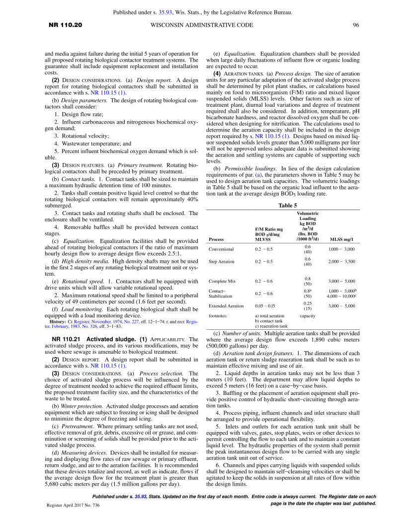
96 NR 110.20 WISCONSIN ADMINISTRATIVE CODE
Published under s. 35.93, Wis. Stats., by the Legislative Reference Bureau.
Published under s. 35.93, Stats. Updated on the first day of each month. Entire code is always current. The Register date on each
page is the date the chapter was last published.Register April 2017 No. 736
and media against failure during the initial 5 years of operation forall proposed rotating biological contactor treatment systems. Theguarantee shall include equipment replacement and installationcosts.
(2) DESIGN CONSIDERATIONS. (a) Design report. A designreport for rotating biological contactors shall be submitted inaccordance with s. NR 110.15 (1).
(b) Design parameters. The design of rotating biological con-tactors shall consider:
1. Design flow rate;
2. Influent carbonaceous and nitrogenous biochemical oxy-gen demand;
3. Rotational velocity;
4. Wastewater temperature; and
5. Percent influent biochemical oxygen demand which is sol-uble.
(3) DESIGN FEATURES. (a) Primary treatment. Rotating bio-logical contactors shall be preceded by primary treatment.
(b) Contact tanks. 1. Contact tanks shall be sized to maintaina maximum hydraulic detention time of 100 minutes.
2. Tanks shall contain positive liquid level control so that therotating biological contactors will remain approximately 40%submerged.
3. Contact tanks and rotating shafts shall be enclosed. Theenclosure shall be ventilated.
4. Removable baffles shall be provided between contactstages.
(c) Equalization. Equalization facilities shall be providedahead of rotating biological contactors if the ratio of maximumhourly design flow to average design flow exceeds 2.5:1.
(d) High density media. High density shafts may not be usedin the first 2 stages of any rotating biological treatment unit or sys-tem.
(e) Rotational speed. 1. Contactors shall be equipped withdrive units which will allow variable rotational speed.
2. Maximum rotational speed shall be limited to a peripheralvelocity of 49 centimeters per second (1.6 feet per second).
(f) Load monitoring. Each rotating biological shaft shall beequipped with a load monitoring device.
History: Cr. Register, November, 1974, No. 227, eff. 12−1−74; r. and recr. Regis-ter, February, 1983, No. 326, eff. 3−1−83.
NR 110.21 Activated sludge. (1) APPLICABILITY. Theactivated sludge process, and its various modifications, may beused where sewage is amenable to biological treatment.
(2) DESIGN REPORT. A design report shall be submitted inaccordance with s. NR 110.15 (1).
(3) DESIGN CONSIDERATIONS. (a) Process selection. Thechoice of activated sludge process will be influenced by thedegree of treatment needed to achieve the required effluent limits,the proposed treatment facility size, and the characteristics of thewaste to be treated.
(b) Winter protection. Activated sludge processes and aerationequipment which are subject to freezing or icing shall be designedto minimize the degree of freezing and icing.
(c) Pretreatment. Where primary settling tanks are not used,effective removal of grit, debris, excessive oil or grease, and com-minution or screening of solids shall be provided prior to the acti-vated sludge process.
(d) Measuring devices. Devices shall be installed for measur-ing and displaying flow rates of raw sewage or primary effluent,return sludge, and air to the aeration facilities. It is recommendedthat these devices totalize and record, as well as indicate, flows ifthe average design flow for the treatment plant is greater than5,680 cubic meters per day (1.5 million gallons per day).
(e) Equalization. Equalization chambers shall be providedwhen large daily fluctuations of influent flow or organic loadingare expected to occur.
(4) AERATION TANKS. (a) Process design. The size of aerationunits for any particular adaptation of the activated sludge processshall be determined by pilot plant studies, or calculations basedmainly on food to microorganism (F/M) ratio and mixed liquorsuspended solids (MLSS) levels. Other factors such as size oftreatment plant, diurnal load variations and degree of treatmentrequired shall also be considered. In addition, temperature, pHbicarbonate hardness, and reactor dissolved oxygen shall be con-sidered when designing for nitrification. The calculations used todetermine the aeration capacity shall be included in the designreport required by s. NR 110.15 (1). Designs based on mixed liq-uor suspended solids levels greater than 5,000 milligrams per literwill not be approved unless adequate data is submitted showingthe aeration and settling systems are capable of supporting suchlevels.
(b) Permissible loadings. In lieu of the design calculationrequirements of par. (a), the parameters shown in Table 5 may beused to design aeration tank capacities. The volumetric loadingsin Table 5 shall be based on the organic load influent to the aera-tion tank at the average design BOD5 loading rate.
Table 5
Process
F/M Ratio mg
BOD 5/d/mg
MLVSS
Volumetric
Loading
kg BOD
/m3/d
(lbs. BOD
/1000 ft3/d) MLSS mg/1
Conventional 0.2 − 0.50.6(40)
l,000 − 3,000
Step Aeration 0.2 − 0.50.6(40)
2,000 − 3,500
Complete Mix 0.2 − 0.60.8(50)
3,000 − 5,000
Contact−Stabilization
0.2 − 0.60.8a
(50) l,000 − 3,000b
4,000 − 10,000c
Extended Aeration 0.05 − 0.l50.25(15)
3,000 − 5,000
footnotes: a) total aerationb) contact tankc) reaeration tank
capacity
(c) Number of units. Multiple aeration tanks shall be providedwhere the average design flow exceeds 1,890 cubic meters(500,000 gallons) per day.
(d) Aeration tank design features. 1. The dimensions of eachaeration tank or return sludge reaeration tank shall be such as tomaintain effective mixing and use of air.
2. Liquid depths in aeration tanks may not be less than 3meters (10 feet). The department may allow liquid depths toexceed 5 meters (16 feet) on a case−by−case basis.
3. Baffling or the placement of aeration equipment shall pro-vide positive control of hydraulic short−circuiting through aera-tion tanks.
4. Process piping, influent channels and inlet structure shallbe arranged to provide operational flexibility.
5. Inlets and outlets for each aeration tank unit shall beequipped with valves, gates, stop plates, weirs or other devices topermit controlling the flow to each tank and to maintain a constantliquid level. The hydraulic properties of the system shall permitthe peak instantaneous design flow to be carried with any singleaeration tank unit out of service.
6. Channels and pipes carrying liquids with suspended solidsshall be designed to maintain self−cleansing velocities or shall beagitated to keep the solids in suspension at all rates of flow withinthe design limits.

97 NR 110.22DEPARTMENT OF NATURAL RESOURCES
Published under s. 35.93, Wis. Stats., by the Legislative Reference Bureau.
Published under s. 35.93, Stats. Updated on the first day of each month. Entire code is always current. The Register date on each
page is the date the chapter was last published. Register April 2017 No. 736
7. All aeration tanks shall have a freeboard of not less than 46centimeters (18 inches).
(5) AERATION SYSTEMS. (a) General. The aeration systemshall be capable of meeting the oxygen requirements of the acti-vated sludge system, or of maintaining adequate mixing of themixed liquor suspended solids, whichever is greater.
(b) Oxygen demand. 1. Aeration equipment shall be capableof maintaining a minimum mixed liquor dissolved oxygen con-centration of 2 milligrams per liter.
2. In the absence of experimentally determined values, thedesign oxygen requirements for all activated sludge processesshall be 1.1 kilograms oxygen per kilogram peak hour BOD5 (1.1pounds oxygen per pound peak hour BOD5) removed in the aera-tion tanks, with the exception of the extended aeration process, forwhich the value shall be 1.5 kilograms oxygen per kilogram peakhour BOD5 (1.5 pounds oxygen per pound peak hour BOD5) toinclude endogenous respiration requirements.
3. To provide nitrification, the oxygen requirement for oxi-dizing ammonia shall be added to the requirement in subd. 2. forcarbonaceous BOD5 removal and endogenous respirationrequirements. In the absence of experimentally determined val-ues, the nitrogen oxygen demand (NOD) shall be 4.6 kilogramsof oxygen per kilogram removed peak hour total Kjeldahl nitro-gen (TKN) (4.6 pounds oxygen per pound removed peak hourTKN).
(c) Air supply to meet oxygen demands. 1. The design of theaerator system to provide the oxygen requirements calculated inaccordance with par. (b) shall be done using standard design equa-tions for diffused and mechanical aeration systems. Calculationsshall incorporate such factors as tank depth, alpha factor of thewaste, beta factor of the waste, certified aerator oxygen transferefficiency, minimum aeration tank dissolved oxygen concentra-tion, critical wastewater temperature and altitude of the waste-water treatment facility.
2. In the absence of specific design information, the airrequirements for diffused aerators shall be calculated using anoxygen transfer efficiency of 7% in clean water under standardtest conditions. The air requirements for mechanical aeratorsshall be based on a transfer rate of 1.2 kilograms oxygen per kilo-watt−hour (2 pounds oxygen per horsepower−hour) in clean waterunder standard test conditions.
(d) Mixing requirements. The following minimum require-ments shall be met to insure adequate mixing of mixed liquor sus-pended solids.
1. Diffused aeration systems shall be capable of delivering aminimum air flow rate of 20 cubic meters per minute per 1,000cubic meters (20 cubic feet per minute per 1,000 cubic feet) of aer-ation volume.
2. Mechanical aerators shall deliver a minimum of 15 kilo-watts per 1,000 cubic meters (0.6 horsepower per 1,000 cubicfeet) of aeration volume.
(e) Other air−use demands. The aeration system shall also becapable of providing the air required for channel aeration, air−liftpumps, aerobic digesters, and any other air−use demand.
(6) AERATION EQUIPMENT. (a) Diffused aeration systems. 1.Multiple blowers shall be provided. The blowers shall be sized tomeet the maximum air demand with the largest blower out of ser-vice. The design shall also provide for varying the volume of airdelivered in proportion to the air demand of the plant.
2. Diffusers and air piping shall be capable of supplying thepeak hour air demand or 200% of the design average air demand,whichever is larger.
3. The arrangement of diffusers shall permit their removal forinspection, maintenance and replacement without dewatering aer-ation tanks or channels and without shutting off the air supply toother diffusers in the treatment system. The department maywaive this requirement for systems with multiple aeration tanks
provided the treatment efficiency of the system can be maintainedwith one aeration tank out of service.
(b) Mechanical aerators. 1. Multiple mechanical aerationunits shall be designed and located so as to meet the peak houroxygen demand or 200% of the design average oxygen demand,whichever is larger, with one unit out of service.
2. Due to high heat loss, the mechanical aerators shall be pro-tected from freezing.
(c) Pure oxygen. Where pure oxygen is proposed, supportingdata from pilot plant installations or full−scale installations simi-lar to the one proposed shall be submitted to justify the aeratorloading rate and the amount and type of aeration capacity andequipment proposed.
(7) SLUDGE EQUIPMENT. (a) Return sludge rate. The rate ofsludge return expressed as a percentage of the average design flowof sewage shall lie within the limits shown in Table 6:
Table 6
Minimum Maximum
Conventional 15 75
Step aeration 20 75
Contact stabilization 50 150
Extended aeration 50 200
Complete mix 20 75
(b) Return sludge pumps. 1. If motor driven return sludgepumps are used, the maximum return sludge capacity shall be metwith the largest pump out of service. A positive head shall be pro-vided on pump suctions. Pumps shall also have at least 7.6 centi-meter (3−inch) suction and discharge openings.
2. If air lifts are used for returning sludge from each settlingtank hopper, no standby unit will be required provided the designof the air lifts allows rapid and easy cleaning. Air lift pumps shallbe designed to provide positive control of the return sludge rate.
(c) Return sludge piping. Suction piping and discharge pipingfor returning activated sludge shall be at least 10 centimeters (4inches) in diameter and must be designed to maintain a velocityof not less than 60 centimeters per second (2 feet per second) atnormal return sludge rates. Suitable devices for observing, sam-pling and controlling return activated sludge flow from each set-tling tank shall be provided.
(d) Waste sludge piping. Waste sludge piping shall complywith the requirements of s. NR 110.26 (4)
(e) Waste sludge pumps. Variable speed or multiple constantspeed waste sludge pumps shall be provided. The maximumsludge pumping rate shall be at least 200% of the anticipated volu-metric sludge production rate. Devices for measuring waste acti-vated sludge flow rates shall be provided.
History: Cr. Register, November, 1974, No. 227, eff. 12−1−74; r. and recr. Regis-ter, February, 1983, No. 326, eff. 3−1−83; CR 09−123: am. (4) (b), (d) 5., (5) (b) 2.,3., (c) 2., (6) (a) 2., (b) 1. and Table 5 (title) Register July 2010 No. 655, eff. 8−1−10.
NR 110.22 Physical−chemical treatment. (1) APPLI-CABILITY. Physical−chemical treatment processes may be usedwhere appropriate to achieve the required effluent limits.
(2) DESIGN REPORT. A design report shall be submitted inaccordance with s. NR 110.05 (1). The report shall detail any labtesting, pilot plant studies or operating experience used to designthe physical−chemical process.
(3) CHEMICAL TREATMENT. (a) Chemical selection. Selectionof chemicals used in chemical treatment shall be based on thecharacteristics of the wastewater and constituents to be removed.
(b) Design basis. 1. Design of chemical treatment processesshall be based on laboratory testing, pilot plant studies or practicaloperating experience.
2. Design of chemical treatment equipment, reactors, andappurtenances shall consider:
a. The chemical requirements and feed rates;

98 NR 110.22 WISCONSIN ADMINISTRATIVE CODE
Published under s. 35.93, Wis. Stats., by the Legislative Reference Bureau.
Published under s. 35.93, Stats. Updated on the first day of each month. Entire code is always current. The Register date on each
page is the date the chapter was last published.Register April 2017 No. 736
b. The location of chemical injection into the waste stream;
c. The need for rapid mixing and flocculation basins;
d. The settling characteristics of the chemical sludge;
e. The need for pH adjustment to optimize chemical reac-tions; and
f. The velocity of waste streams in flow conduits to minimizedestruction of floc.
(c) Phosphorus removal. 1. Addition of lime or the salts ofaluminum or iron may be used for the chemical precipitation ofsoluble phosphorus.
2. The addition of polyelectrolytes to aid in the settling ofphosphate precipitates should be considered.
3. Chemicals shall be mixed rapidly and thoroughly with thewastewater.
(4) HAZARDOUS CHEMICAL HANDLING. (a) Safety. 1. Eye−wash fountains and safety showers using potable water shall beprovided in the laboratory and on each floor level or work locationwhere hazardous chemicals are stored, mixed or slaked, pumped,metered or unloaded. These fountains and showers shall be lessthan 7.6 meters (25 feet) from points of exposure to hazardouschemicals and shall be fully usable during all weather conditions.
2. Eye−wash fountains shall be supplied with water with atemperature not exceeding 38°C (100°F). This supply shall beseparate from the hot water supply and be able to provide 15 to 30minutes of continuous irrigation of the eyes.
3. Safety showers shall be capable of discharging 1.9 to 3.2liters per second (30 to 50 gallons per minute) of water with a tem-perature not exceeding 38°C (100°F) temperature, and at pres-sures of 1.41 to 3.52 kilograms force per square centimeter (20 to50 pounds per square inch).
4. The following protective clothing and equipment shall beavailable for use with all operations or procedures in which theiruse will minimize the risk of injury to personnel:
a. Chemical worker’s goggles or other suitable goggles(safety glasses are insufficient);
b. Face masks or shields for use over goggles;
c. Rubber gloves;
d. Rubber aprons with leg straps;
e. Rubber boots; and
f. Safety harness and line.
5. Warning signs shall be installed where appropriate.
(b) Storage requirements. 1. The materials used for storingof hazardous chemicals shall be selected based on the physical andchemical characteristics of each chemical used.
2. Chemical storage areas shall be enclosed by dikes or curbswhich will contain the stored volume in case of a spill until it canbe either safely transferred to another storage area or released tothe wastewater at a controlled rate which will not damage thetreatment facilities, inhibit the treatment processes, or contributeto stream pollution. Liquid polymer shall be similarly contained.
3. Chemical storage and mixing areas shall be separate fromother treatment plant functions.
4. Nonslip floor surfaces are desirable in polymer handlingareas.
(c) Pumping and piping requirements. 1. The materials usedfor piping, valves, pumping, metering, splash guards and anyother equipment used to convey hazardous chemicals shall beselected based on the physical and chemical characteristics ofeach chemical used.
2. All piping containing or transporting hazardous chemicalsshall be identified with labels every 3 meters (10 feet) and with atleast 2 labels in each room, closet or pipe chase. Color coding mayalso be used but is not an adequate substitute for labeling.
3. All pumps or feeders for hazardous or corrosive chemicalsshall have splash guards which will effectively prevent spray ofchemicals into space occupied by workers. The splash guards are
in addition to guards to prevent injury from moving or rotatingmachinery parts. All connections except those adjacent to storageor feeder areas shall have guards which will direct any leakageaway from space occupied by workers.
4. Exposed pipes containing hazardous chemicals may not belocated above shoulder level except where continuous drip collec-tion trays and coupling guards will eliminate the spraying or drip-ping of these chemicals onto workers.
(5) PHYSICAL TREATMENT. (a) Design. Physical treatmentshall be evaluated on a case−by−case basis. The design shall bebased on pilot plant studies or operating experience.
(b) Filtration. 1. Selection of type, size, and depth of filtermedia shall depend on the filtration rate, the type of treatment pro-vided prior to filtration, filter configuration, available hydraulichead, and the desired effluent quality.
2. Multiple filters shall be provided.
3. For high rate effluent filtration, the filtration rate at maxi-mum hour design flow may not exceed 3.4 liters per second persquare meter (5 gallons per minute per square foot). The filtrationrate shall be calculated on the total available filter area with onefilter unit out of service.
4. Provisions shall be made for backwashing each filter. Thebackwash system shall be capable of providing a variable back-wash rate with a maximum rate sufficient to fluidize the filteringmaterial. A minimum backwash period of 10 minutes shall beprovided.
5. Air scour for aiding backwashing is recommended.
6. Provision shall be made for chlorinating each filter.
7. Backwash reservoirs shall be provided. Total backwashwater storage provided shall equal or exceed the volume requiredfor 2 complete backwash cycles.
8. Spent backwash water shall be individually treated orreturned to the head of the treatment facility. The return rate ofbackwash to the head of the treatment facility may not exceed 15%of the average design flow rate.
(c) Microstraining. 1. Multiple screening units shall be pro-vided.
2. The screening rate at maximum daily design flow may notexceed 3.4 liters per second per square meter (5 gallons per minuteper square foot) based on submerged area with one screening unitout of service.
3. Provisions shall be made for backwashing each unit. Thebackwash system shall be capable of delivering at least 1.7 litersper second per meter (8 gallons per minute per foot) of filterlength. Backwash shall be delivered at 4.2 kilograms force persquare centimeter (60 pounds per square inch).
4. Spent backwash shall be individually treated or returned tothe head of the treatment facility. The return rate of backwash tothe head of the treatment facility may not exceed 15% of the aver-age design flow rate.
(6) RECIRCULATING SAND FILTERS. (a) Applicability. Recircu-lating sand filters may be approved on a case−by−case basis.
(b) Primary treatment. Recirculating sand filters shall be pre-ceded by a minimum of primary treatment.
(c) Recirculation tanks. Recirculation tanks shall be equippedwith a highwater and pump failure alarm.
(d) Maintenance. Recirculation tanks and sand filters shall bereadily accessible for inspection and maintenance.
(7) INTERMITTENT SAND FILTERS. (a) Applicability. Intermit-tent sand filters may be approved on a case−by−case basis.
(b) Primary treatment. Intermittent sand filters shall be pre-ceded by a minimum of primary treatment.
(c) Loading. 1. The loading rate for installations which oper-ate with significant rest periods may not exceed 41 liters persquare meter (one gallon per square foot) per day, at the averagedesign flow.

99 NR 110.23DEPARTMENT OF NATURAL RESOURCES
Published under s. 35.93, Wis. Stats., by the Legislative Reference Bureau.
Published under s. 35.93, Stats. Updated on the first day of each month. Entire code is always current. The Register date on each
page is the date the chapter was last published. Register April 2017 No. 736
2. The loading rate for filters which operate on a continuousbasis may not exceed 20 liters per square meter (0.5 gallons persquare foot) per day, at the average design flow, for total bed area.
(d) General requirements. 1. Duplicate filters shall be pro-vided.
2. Intermittent sand filters shall be sealed in compliance withthe provisions of s. NR 110.24 (4).
3. Intermittent sand filters shall be underdrained. Under-drains may be constructed of open jointed or perforated clay, con-crete or plastic pipe. Underdrain spacing may not exceed 3 meters(10 feet) on center.
(e) Media. 1. Clean graded gravel shall be placed around theunderdrains. Depth of the gravel shall be at least 15 centimeters(6 inches) over of the top of the underdrains.
2. At least 60 centimeters (2 feet) of clean sand shall be placedover the gravel. The effective size of the sand shall be 0.3 to 0.6millimeter (0.01 to 0.02 inches) with a uniformity coefficient of3.5.
(f) Buried sand filters. 1. Distribution piping shall have a min-imum diameter of 10 centimeters (4 inches). Spacing of dis-tribution pipes may not exceed 3 meters (10 feet). Distributionpipes may not be placed directly above underdrains.
2. The distribution piping shall be vented to the atmosphere.
3. Buried sand filters shall be dosed by pumps or siphons. Thedosing volume shall be 90% of the volume of the distribution pip-ing. The dosing system and distribution piping shall be sized tohandle the average daily design flow.
4. Buried sand filters shall be covered by a minimum of 91centimeters (36 inches) of soil.
(g) Exposed sand filters. 1. Exposed filters may be used whenthe filter will be designed to operate during the summer months.
2. Distribution troughs or piping shall be spaced not morethan 6 meters (20 feet) on center.
3. Splash pads shall be provided at each point of discharge.
4. Exposed sand filters shall be dosed by pumps or siphons.The dosing volume shall be sufficient to cover the filter with 3 to6 centimeters (2 to 4 inches) of effluent. The dosing system shallbe sized to handle the average daily design flow.
5. Exposed sand filters shall have a freeboard of at least 60centimeters (2 feet).
History: Cr. Register, November, 1974, No. 227, eff. 12−1−74; r. and recr. Regis-ter, February, 1983, No. 326, eff. 3−1−83; CR 09−123: am. (5) (b) 3., (c) 4., (6) (c)and (7) (c) Register July 2010 No. 655, eff. 8−1−10; CR 12−027: am. (5) (b) 2., (c)1. Register July 2013 No. 691, eff. 8−1−13.
NR 110.23 Disinfection. (1) GENERAL. (a) Applicability.Disinfection shall be provided in accordance with WPDES permitrequirements.
(b) Effluent limitations. 1. When chlorine is used as the disin-fectant, the residual concentration in the wastewater treatmentfacility effluent shall comply with WPDES permit requirements.
2. Effluent bacterial concentrations shall conform withWPDES permit requirements.
(c) Process selection. 1. The selection of the method of disin-fection shall be based on a cost effective comparison of disinfec-tion methods.
2. Where a disinfection process other than chlorine is pro-posed, supporting data from pilot plant installations or similarfull−scale installations shall be submitted as a basis for the designof the system in accordance with s. NR 110.15 (1).
(2) DISINFECTION WITH CHLORINE. (a) Storage requirements.1. If a gas chlorinator and chlorine cylinders are installed in abuilding used for other purposes, the chlorinator and chlorine cyl-inders shall be separated from all other portions of the building bybeing kept in a gas−tight room. Doors to this room shall open onlyto the outside of the building, and shall be equipped with panic oremergency hardware. Those rooms shall be at or slightly above
grade and must permit easy access to all equipment. If one ton orlarger cylinders of chlorine are used, the chlorination equipmentshall be kept in a room separate from the chlorine cylinders.
2. A clear glass, gas−tight window shall be installed in anexterior door or interior wall of the chlorinator room to permit thechlorinator to be viewed without entering the room.
3. Chlorinator and chlorine cylinder storage rooms shall beprovided with a means of heating so that a temperature of at least16°C (60°F) can be maintained. The rooms shall be protectedagainst temperatures exceeding 65°C (140°F).
4. Forced, mechanical ventilation of the chlorinator room andthe chlorine storage room shall be installed. Ventilation equip-ment shall be capable of providing one complete air change perminute. The entrance to the air exhaust duct from the room shallbe near the floor and the point of discharge shall be so located asnot to contaminate the air inlet to any buildings or inhabited areas.Air inlets shall be so located as to provide cross ventilation and atsuch a temperature that will not adversely affect the chlorinationequipment. The vent hose from the chlorinator shall discharge tothe outside atmosphere above grade.
5. The controls for the ventilator and lights shall be such thatthe ventilator and lights will automatically operate when the dooris opened but must be manually switched off even if the door clo-ses. Switches shall also be provided to allow manual operation ofthe lights and ventilator from outside of the room without openingthe door.
6. One ton cylinders shall be used at treatment facilities wherethe chlorine use rate exceeds 68 kilograms (150 pounds) per day.
(b) Feed equipment. 1. Solution−feed vacuum type chlorina-tors or positive displacement type hypochlorite feeders shall beused.
2. An ample supply of water shall be supplied for operatingthe chlorinator.
3. Chlorinators and feed equipment shall be sized to handlethe maximum design chlorine demand.
4. Chlorinators shall be equipped to provide control of chlo-rine application through the full range of design chlorine demand.If necessary, more than one rotometer shall be supplied to ensurecontrol of chlorine application through the design range.
5. Scales or other means of determining chlorine usage shallbe provided. Scales shall be of corrosion−resistant material.
6. Evaporators for converting liquid chlorine to a gas may beused if necessary.
(c) Piping and connections. 1. Only piping systems specifi-cally manufactured for chlorine service shall be used.
2. Due to the corrosiveness of wet chlorine, all lines designedto handle dry chlorine shall be protected from the entry of wateror air containing water.
(d) Chlorine control systems. In all systems with an averagedesign flow of greater than 945 cubic meters per day (0.25 milliongallons per day), the chlorine feed mechanism shall be providedwith either an automatic flow proportional control or an automaticresidual control. Chlorine residual analyzers shall be located nearthe chlorine contact tank. The total response time for automaticresidual control systems may not exceed 3 minutes.
(e) Application. 1. The chlorine shall be mixed as rapidly aspossible. This may be accomplished by either the design of a tur-bulent flow regime or the use of a mechanical flash mixer.
2. A chlorine contact tank shall be provided and shall be sizedto provide a detention time of 60 minutes at average design flowor 30 minutes at maximum hour design flow.
3. Chlorine contact tanks shall be baffled to provide a flowchannel with a minimum length to width ratio of 40:1.
4. The department may approve contact tanks which do notcomply with the requirements of this paragraph. Such facilities,

100 NR 110.23 WISCONSIN ADMINISTRATIVE CODE
Published under s. 35.93, Wis. Stats., by the Legislative Reference Bureau.
Published under s. 35.93, Stats. Updated on the first day of each month. Entire code is always current. The Register date on each
page is the date the chapter was last published.Register April 2017 No. 736
however, shall be field tested to demonstrate that short circuitingof hydraulic flow through the contact chamber does not occur.
(f) Dechlorination. 1. Dechlorination shall be provided inaccordance with WPDES permit requirements.
2. Dechlorination chemicals shall be rapidly mixed with theeffluent.
3. Sulfur dioxide dechlorination systems shall be designed inthe same manner as chlorination systems.
4. Effluent reaeration shall be provided after dechlorinationif necessary to insure adequate dissolved oxygen concentration inthe receiving stream.
5. Dechlorinated effluent shall be monitored for chlorineresidual and dissolved oxygen in accordance with WPDES permitrequirements.
(g) Safety equipment. 1. Respiratory air−pack protectionequipment, meeting the requirements of the national institute foroccupational safety and health (NIOSH) shall be available wherechlorine gas is handled, and shall be stored at a convenient loca-tion. The equipment may not be stored inside any room in whichchlorine is used and stored. The equipment shall use compressedair or oxygen, have at least a 30−minute capacity, and be compat-ible with the units used by the fire department having jurisdictionover the plant.
2. A plastic bottle of ammonium hydroxide shall be providedfor the detection of chlorine leaks.
3. Leak repair kits shall be provided when one ton chlorinecylinders are used.
(3) ULTRAVIOLET DISINFECTION. Provisions shall be made toclean ultraviolet units without loss of disinfection. This shall beaccomplished by installing multiple ultraviolet units, by provid-ing ultrasonic cleaners, or by providing an effluent holding tankwith a capacity of one hour detention at average design flow.
History: Cr. Register, November, 1974, No. 227, eff. 12−1−74; r. and recr. Regis-ter, March, 1978, No. 267, eff. 4−1−78; r. and recr. Register, February, 1983, No. 326,eff. 3−1−83; CR 09−123: am. (2) (d) and (e) 2. Register July 2010 No. 655, eff.8−1−10.
NR 110.24 Lagoons. (1) DESIGN REPORT. A design reportshall be submitted in accordance with s. NR 110.15 (1).
(2) BASIS OF DESIGN. (a) Number of cells. A minimum of 2treatment cells shall be provided for aerated lagoons and stabiliza-tion ponds. Where a controlled discharge is required, additionaleffluent storage cells shall be provided.
1. For aerated lagoons designed to treat domestic wastewateronly, the hydraulic detention time of each cell shall be based onthe following formula:
T� EK(100� E)
Where:
T = detention time, days
E = BOD removal efficiency, percent
K = Reaction coefficient (log base e), days−1
a. For domestic wastewater K = 0.5 at 20°C.
b. The reaction coefficient (K) must be adjusted for tempera-ture according to the formula:
KT = K20ΘT−20
Where:
KT = Corrected reaction coefficient
K20 = 0.5
Θ = 1.07
T = Low design temperature, °C
2. The appropriate summertime and wintertime reaction coef-ficients for aerated lagoons designed to treat combined domesticand industrial wastewater shall be determined from laboratory orpilot studies, or from operating data of existing full scale aeratedlagoons which are treating similar wastewater. The reaction coef-
ficients developed shall be used to calculate the required detentiontime.
3. In addition to the treatment volume calculated in subd. 1.or 2., quiescent settling zone or cell shall be provided for aeratedlagoon systems. Minimum settling time shall be 6 days for surfacewater discharge, and 3 days for land disposal discharge.
4. Aerated lagoons designed to treat combined domestic andindustrial wastewater shall be provided with the means to recircu-late final lagoon effluent to the first treatment cell.
(b) Stabilization ponds. 1. Stabilization ponds may be usedto treat domestic wastewater. Combined domestic and industrialwastewater may be treated in stabilization ponds only if the treat-ability of the industrial wastewater is demonstrated through pilottesting.
2. The BOD5 loading to any one stabilization pond may notexceed 23 kilograms per hectare (20 pounds per acre) per day.
3. A minimum hydraulic detention time of 150 days at theaverage design flow shall be provided in the entire stabilizationpond system. In accordance with s. NR 210.06 (3) (h), a stabiliza-tion pond system which discharges to surface water, and has ahydraulic detention time of 180 days or longer at average designflow, does not require disinfection except in extenuating circum-stances.
(3) DESIGN REQUIREMENTS. (a) Location. Lagoon systemsshall be located in compliance with s. NR 110.15 (3) (b) and (c).
(b) Separation from groundwater. 1. For all lagoons not sealedwith a synthetic liner, a minimum separation distance of 1.25meters (4 feet) shall be maintained between the bottom of lagoonsand the highest recorded or indicated seasonal groundwater tableelevation.
2. For all lagoons sealed with a synthetic liner, a minimumseparation distance of 60 centimeters (2 feet) shall be maintainedbetween the bottom of the lagoon and the highest recorded or indi-cated seasonal groundwater table elevation.
(c) Separation from bedrock. A minimum separation of 3meters (10 feet) shall be maintained between the bottom oflagoons and bedrock. The department may waive this require-ment on a case−by−case basis if it can be demonstrated that alesser separation distance will not cause groundwater qualityproblems. Criteria which will be evaluated to waive this require-ment include the depth to bedrock, the type of bedrock, the frac-ture condition of the bedrock, the direction of groundwater move-ment, the existing groundwater quality, and the downgradientuses of the groundwater.
(d) Test pits and soil borings. 1. Backhoe test pits and soil bor-ings shall be conducted at each proposed lagoon site. Logs of thetest pits and soil borings shall be submitted with the facilities planas required in s. NR 110.09 (8) (a). Soil boring and test pit analy-ses shall be conducted by an independent soil testing laboratory,a qualified engineering firm or an individual or firm which hasdemonstrated the capability to perform and evaluate such tests.
2. Soil borings and test pits shall be used to determine subsur-face soil characteristics and variability, seasonal high groundwa-ter level and elevations, and type, nature and depth to bedrock.Soils shall be classified according to the unified soil classificationsystem. Cross−sections using the soil boring and test pit logs shallbe prepared and submitted with the facilities plan.
3. Soil sampling shall be performed in accordance withASTM D1586−08a or ASTM D1587−08.
4. Soil profile descriptions shall be written for all soil test pits.The thickness in inches and the difference between each soil hori-zon shall be indicated for each test pit. Horizons shall be differen-tiated on the basis of color, texture, soil mottles or bedrock. Depthshall be measured from the ground surface and the slope at the testpit shall be indicated.
5. A minimum of one soil boring per acre shall be conductedat each lagoon site. The number of test pits and borings shall be

101 NR 110.24DEPARTMENT OF NATURAL RESOURCES
Published under s. 35.93, Wis. Stats., by the Legislative Reference Bureau.
Published under s. 35.93, Stats. Updated on the first day of each month. Entire code is always current. The Register date on each
page is the date the chapter was last published. Register April 2017 No. 736
sufficient to adequately characterize the soil type and variabilityand delineate unsuitable soil areas in the field. The departmentmay require additional soil borings and test pits to properlydescribe the site soils, bedrock or groundwater conditions.
6. Each boring shall have a minimum depth of 7.6 meters (25feet) or to bedrock.
7. All soil borings in which wells are not installed shall beproperly abandoned according to s. NR 141.25.
8. All test pits shall be refilled with the excavated materials.
(e) Lagoon shape. The shape of lagoons shall be such thatthere are no narrow or elongated portions. Islands, peninsulas orcoves will not be approved. Dikes shall be rounded at corners tominimize accumulations of floating materials. Commonwall dikeconstruction is encouraged. Round, square or rectangular lagoonswith a length not exceeding 3 times the width are recommended.
(f) Dikes. 1. The minimum top width of dikes shall be 3.6meters (12 feet).
2. Maximum dike slopes shall be 3:1 (horizontal to vertical).
3. The minimum allowable interior slope shall be 4:1.
4. A minimum one meter (3 feet) freeboard from operatingwater surface to the top of dikes shall be provided.
(g) Operating water depth. 1. A minimum liquid depth of 0.6meters (2 feet) for stabilization ponds and 1.8 meters (6 feet) foraerated lagoons shall be provided.
2. Maximum water depth may not exceed 1.8 meters (6 feet)for stabilization ponds and 4.3 meters (15 feet) for aeratedlagoons.
(4) SEALING REQUIREMENTS. (a) General. All lagoons shallbe sealed to prevent excessive exfiltration.
(b) Exfiltration rate. 1. Loss of water from wastewater treat-ment or storage lagoons may not exceed 10 cubic meters per watersurface hectare (1,000 gallons per acre) per day and loss of waterfrom sludge storage or treatment lagoons or other sludge handlingfacilities may not exceed 5 cubic meters per sludge surface hectare(500 gallons per acre) per day.
2. In circumstances where soil or groundwater characteris-tics, groundwater quality, or waste characteristics warrant, thedepartment may require exfiltration rates less than 10 cubicmeters per water surface hectare (1,000 gallons per acre) per dayfor wastewater treatment or storage lagoons.
(c) Materials. 1. Soil materials or synthetic liners approvedby the department may be used to seal lagoons.
2. Soil materials or synthetic liners used to seal lagoons shallbe compatible with the wastewater characteristics.
(d) Sampling and testing standards. 1. Core samples taken todetermine soil texture, grain size distribution or permeability shallbe taken in accordance with ASTM D1586−08a, ASTMD1587−08, or ASTM 3550−01 (2007).
2. Permeability shall be determined using a falling head per-meability test. The test shall be performed at the same approxi-mate density as the in−place field condition. Tests on remoldedor undisturbed samples are acceptable.
3. Sieve analyses performed to determine grain size distribu-tion shall be performed in accordance with ASTM D422−63(2007).
4. Plasticity index shall be determined in accordance withASTM D4318−10.
5. Standard procter densities shall be determined in accord-ance with ASTM D698−07 e1.
(e) Uniform construction. All lagoon seals shall be uniformlyconstructed across the lagoon bottom and interior dike walls.Seals shall extend up the dike wall to the berm.
(f) Synthetic liners. 1. Synthetic liners shall have a minimumthickness of 0.8 millimeters (30 mils).
2. All synthetic liners shall be installed under the supervisionof a qualified manufacturer’s representative.
3. Synthetic liners shall be protected by an inorganic soillayer. The soil layer shall have a minimum thickness of 30 centi-meters (one foot). The soil shall be uniformly graded and freefrom large rocks, angular stones, soil clumps, sticks or other mate-rial which may puncture the liner. When a granular, noncohesivesoil is used for the cover, a soil fabric shall be placed between theliner and the soil cover. The soil fabric shall be anchored at thedike berm.
4. Synthetic liners shall be securely anchored to the dikeberm.
5. Synthetic liners shall be vented.
6. Riprap or other means of erosion control shall be providedto prevent exposure of the synthetic liner due to erosion of the pro-tective soil layer.
7. Prior to constructing the synthetic liner, the underlyingsoils shall be treated with a herbicide in accordance with manufac-turers recommendations.
(g) Soil or soil−bentonite liners. 1. The permeability of soilor bentonite liners may not be greater than 1 x 10⁻⁷ cm/sec. (2.83x 10⁻⁴ ft/day).
2. The liner thickness shall be determined according to Dar-cy’s equation, and shall include an appropriate safety factor forconstruction variability. In no case shall the liner thickness be lessthan the minimum values shown in Table 7.
3. When the soil or soil−bentonite liner is to be constructedover the existing soil at the lagoon site, 15% of the soil particlesof the existing soil must pass a no. 200 sieve. If this requirementcannot be met, a soil filter fabric material shall be placed betweenthe liner and the existing soil.
4. Liners shall be compacted at or above optimum moisturecontent.
5. A means shall be provided to prevent the liner from desic-cating after the completion of construction and prior to placing thesystem in operation.
6. Liners shall be protected by an inorganic soil layer. The soillayer shall have a minimum thickness of 10 centimeters (4 inches).The cover shall be uniformly graded and free from large rocks,soil clumps, and sticks.
Table 7
Minimum Liner Thickness
Coefficient of
Permeability
cm/sec (ft/day)
Centimeters
(Inches)
Water Depth
Meters (feet)
1.8 3 3.8 4.6
(6) (10) (12) (15)
1 x 10⁻⁷ 22 cm 33 cm 40 cm 48 cm
(2.83 x 10⁻⁴) (9 in) (13 in) (16 in) (19 in)
5 x 10⁻⁸ 14 19 23 27
(1.42 x 10⁻⁴) (6) (8) (8) (11)
1 x 10⁻⁸ 10 10 10 10
(2.83 x 10⁻⁵) (4) (4) (4) (4)
5 x 10⁻⁹ 10 10 10 10
(1.42 x 10⁻⁵) (4) (4) (4) (4)
1 x 10⁻⁹ 10 10 10 10
(2.83 x 10⁻⁶) (4) (4) (4) (4)
(h) Soil liner material specifications. 1. Soil liners shall con-sist of soils of which more than 50% of the soil particles pass a no.200 sieve. The soil liner shall have a plasticity index of at least 15.
2. Soil liners shall be compacted to at least 95% of the maxi-mum standard proctor density.

102 NR 110.24 WISCONSIN ADMINISTRATIVE CODE
Published under s. 35.93, Wis. Stats., by the Legislative Reference Bureau.
Published under s. 35.93, Stats. Updated on the first day of each month. Entire code is always current. The Register date on each
page is the date the chapter was last published.Register April 2017 No. 736
3. Soil liners shall be constructed and compacted in lifts.Each lift may not exceed a compacted thickness of 15 centimeters(6 inches).
4. Frost susceptible soils may not be used to construct the lin-er. Any soil which is primarily silt, silty sand, or lean clay whichhas a plasticity index less than 12 shall be considered as frost sus-ceptible.
5. Soil liners constructed of natural in−place soils shall be sca-rified prior to compaction.
(i) Bentonite liner material specifications. 1. Bentonite shallbe mixed with a soil in which at least 30% of the soil particles passa no. 200 sieve. The soil shall have a plasticity index of at least15.
2. Bentonite shall be applied at a rate recommended by themanufacturer or independent soil expert. The constructed linershall have a minimum bentonite content of 5% by dry weight.
3. Ninety percent of the bentonite by weight shall pass a no.80 sieve.
4. Bentonite shall be thoroughly mixed with the soil material.
5. The bentonite liner shall be compacted to at least 85% ofthe maximum standard proctor density.
(j) Construction quality testing. 1. All liners shall be testedbefore placing the lagoons into operation to insure compliancewith par. (b). Test results shall be submitted to the department.
2. The method of testing shall be presented to the departmentwith the project plans and specifications.
3. Testing shall be performed in accordance with one of thetesting methods of par. (k).
4. All tests shall be performed under the supervision of thedesign engineer.
(k) Testing methods. 1. All liners may be tested using an in−field full lagoon water balance. The test shall occur over a mini-mum 14−day period. The manner of determining precipitationand evaporation rates shall be shown in the project plans and spec-ifications.
2. The integrity of the field constructed seams for syntheticliners shall be tested with compressed air prior to placing the pro-tective soil cover. All faulty seams shall be repaired and retested.
3. Core samples of soil or soil−bentonite liners may be takenand the liner thickness and permeability measured in a laboratory.Core samples shall be taken in accordance with ASTM D1587(1974). A minimum of 12 samples per wetted hectare (5 samplesper wetted acre) must be analyzed. The samples shall be propor-tionately taken from the lagoon bottoms and dikes. The lagoonliner shall be considered to meet the performance standard of par.(b) if:
a. The average seal thickness of the samples are equal or togreater than the specified design thickness. No sample shall havea thickness more than 1−inch less than the design thickness; and
b. The coefficient of permeability of 90% of the samples mustbe equal to or less than the design coefficient of permeability.
(5) CONSTRUCTION DETAILS. (a) Material. 1. Embankmentsand dikes shall be constructed of relatively impervious materialsand compacted at near optimum moisture content to 95% of thestandard proctor density.
2. Vegetation and other unsuitable materials shall be removedfrom the area where the embankment is to be placed.
(b) Erosion control. 1. Riprap or other means of preventingerosion shall be used at locations on lagoon bottoms and interiordike walls where erosion or activity of burrowing animals is likelyto occur.
2. Riprap or other erosion control methods shall be used onthe exterior dike walls for lagoons which are constructed in a floodfringe.
3. Exterior dike walls, berms and interior dike walls above thenormal operating water depth, shall be riprapped or seeded withperennial, low growing, spreading grasses.
(c) Fencing. Lagoons shall be enclosed within a fence. A vehi-cle access gate shall be provided.
(d) Warning signs. Appropriate signs shall be provided alongthe fence surrounding lagoons to designate the nature of the facil-ity and prohibit trespassing.
(6) AERATION EQUIPMENT. (a) Air requirements. Air shall beprovided to the aerated lagoons at a rate of not less than 1.5 kilo-grams oxygen per kilogram (1.5 pounds of oxygen per pound) ofpeak hour BOD removed.
(b) Surface aeration equipment. 1. The department mayapprove the use of surface aeration equipment only in those casesin which the equipment can be properly maintained and operatedduring the winter.
2. Surface aeration equipment shall be so designed and placedto provide optimum mixing of pond lagoon contents and disper-sion of oxygen to the waste. Unless sufficient justification is pre-sented to the contrary, surface aerators shall be designed using anoxygen transfer rate of 1.2 kilograms of oxygen per kilowatt−hour(2.0 pounds of oxygen per horsepower−hour) in clean water understandard conditions.
(c) Subsurface aeration equipment. 1. Flexible tubing con-taining air release slits shall be provided across the lagoon bottomin accordance with the manufacturer’s recommendations. Airtubing shall be securely anchored to prevent floating. To preventclogging of the air lines, provision shall be made to accommodatecleaning.
2. Air tubing and anchors shall be constructed of materialswhich resist corrosion.
3. Air shall be supplied to the lagoon system at a rate sufficientto meet the oxygen requirements of par. (a) assuming an oxygentransfer efficiency of 7% in clean water under standard conditions.
4. Tubular aeration units shall be provided in sufficient num-ber to supply adequate air to the pond system based on a maximumtransfer rate of 0.6 kilograms (1.25 pounds) of oxygen per unit perhour in clean water under standard conditions.
5. Where data is presented to the department to justify oxygentransfer rates varying from the requirements of this paragraph thedepartment may approve such design transfer rates.
(d) Aeration systems. 1. Multiple blowers shall be provided.Capacity of the blowers shall be sufficient to meet total airdemands with one blower out of service.
2. Diffusers and air piping shall be capable of supplying 200%of the average daily air demand.
(7) HYDRAULIC STRUCTURES. (a) Materials. Influent lines,interconnecting piping, and overflow structures shall be con-structed of materials suitable for underground gravity sewer con-struction.
(b) Capacity. 1. Influent lines to all lagoon systems shall besized in accordance with s. NR 110.13 (4).
2. Overflow structures and interconnecting piping for contin-uous flow lagoon systems shall be sized in accordance with s. NR110.13 (4).
3. Overflow structures and interconnecting piping for con-trolled discharge lagoon systems shall be sized to handle the antic-ipated interlagoon flow rates during periods of discharge.
(c) Influent piping. 1. A manhole shall be installed at the endof the influent line or force main and shall be located as close tothe dike as topography permits. Its invert shall be at least 15 centi-meters (6 inches) above the maximum operating water level of thelagoon to provide sufficient hydraulic head without surchargingthe manhole.

103 NR 110.25DEPARTMENT OF NATURAL RESOURCES
Published under s. 35.93, Wis. Stats., by the Legislative Reference Bureau.
Published under s. 35.93, Stats. Updated on the first day of each month. Entire code is always current. The Register date on each
page is the date the chapter was last published. Register April 2017 No. 736
2. Influent lines shall be located such that the top of the pipeis at least 15 centimeters (6 inches) below the lower surface of thesoil, bentonite, or synthetic liner.
3. For circular lagoons, the inlet shall terminate at the centerof the lagoon. Influent lines to rectangular or square lagoons shallterminate in the first one third of the lagoon length. Influent andeffluent piping shall be located to minimize short−circuitingwithin the lagoon.
4. The inlet line shall discharge either horizontally onto a con-crete pad or by means of an upturned elbow terminating at least30 centimeters (one foot) above the pond bottom.
(d) Overflow structures. An overflow structure shall be pro-vided and shall consist of either a manhole or box equipped withmultiple−valved pond drawoff lines or an adjustable overflowdevice. The overflow structure shall allow the liquid level of thelagoon to be adjusted to permit operation at depths ranging from60 centimeters (2 feet) to the maximum design operating depth instabilization ponds and from 1.2 meters (6 feet) to the maximumdesign operating depth in aerated lagoons. The department rec-ommends that stop planks not be used in overflow structures tocontrol operating depth.
History: Cr. Register, November, 1974, No. 227, eff. 12−1−74; r. and recr. Regis-ter, February, 1983, No. 326, eff. 3−1−83, am. (3) (c) and (4) (b), r. and rec. (3) (d),Register, November, 1990, No. 419, eff. 12−1−90; CR 09−123: am (2) (b) 2., 3., (3)(d) 3., (4) (d) 1., 3. to 5., (6) (a), (b) 2., (c) 3. and 4. Register July 2010 No. 655, eff.8−1−10.
NR 110.25 General conditions required for all landdisposal systems. The provisions of this section apply to allmunicipal and privately owned domestic sewage treatmentworks.
(1) APPLICABILITY. Land disposal systems shall be reviewedand approved on a case−by−case basis.
(2) DESIGN REPORT. A design report shall be submitted inaccordance with s. NR 110.15 (1).
(3) TREATMENT PRIOR TO DISPOSAL. All discharges to land dis-posal systems shall receive biological, chemical, physical or acombination of treatments necessary to meet effluent standards inch. NR 206 and groundwater quality standards in ch. NR 140 asapproved by the department. Industrial waste discharges tributaryto the municipal system shall be in compliance with applicablepretreatment standards under s. NR 211.30.
(3m) MANAGEMENT PLAN. (a) A management plan shall besubmitted with plans and specifications for all land disposal facili-ties.
(b) The management plan shall contain specific informationon pretreatment processes, scheduled maintenance, vegetativecover control and removal, load and rest schedules, applicationrates, operational strategies for periods of adverse weather, moni-toring procedures and other pertinent information.
(4) DESIGN REQUIREMENTS. (a) Application rates. 1. Theapplication rate of wastewater may not exceed the long term infil-trative capacity of the soil.
2. The application rate of wastewater containing heavy metalsmay not exceed the soil capacity for preventing the movement ofthe heavy metals through the soil.
3. Multiple wastewater application areas shall be provided toallow load and rest cycles. The discharge shall be alternately dis-tributed to individual cells of the disposal system in a manner toallow sufficient resting periods to maintain the absorptive capac-ity of the soil, and to allow soil conditions to become unsaturatedand aerobic between loadings.
(c) Separation from water supplies. 1. Land disposal systemsshall be separated from private water supply wells by a minimumhorizontal distance of 76 meters (250 feet).
2. The minimum horizontal separation distance between aland disposal system and public water supply wells shall be deter-mined during facilities planning in accordance with s. NR 110.09
(2) (p). In all cases the department recommends a minimum hori-zontal separation of 305 meters (1,000 feet) be maintained.
(e) Storage lagoons. Storage lagoons shall be provided for allland disposal systems which are adversely affected by winter con-ditions or wet weather. Storage lagoons shall be constructed inaccordance with s. NR 110.24 (3) and (4).
(f) Load and rest cycles. Load and rest cycles for each systemshall be determined based on hydrogeologic and other relevantsite conditions such as soil permeability, texture, cation−exchangecapacity, topography, depth to groundwater and bedrock and thewastewater characteristics.
(g) Construction precautions. 1. All precautions shall betaken during construction of a land disposal system to minimizecompaction of absorption areas and to prevent reduction in soilinfiltration rate. Project specifications shall detail the specific pre-cautions to take, which may include no heavy equipment use anderosion control on berms.
2. Erosion control measures shall be practiced during the con-struction of the land disposal system to avoid erosion of soil intoa surface water and into or from the land disposal system.
(5) GROUNDWATER MONITORING. (a) Applicability. Ground-water monitoring systems shall be installed in accordance withapproved plans and specifications as required in ch. NR 108, forthe purpose of determining groundwater conditions for the engi-neering report in s. NR 110.09 (1) (b) and for WPDES permitrequirements. Plans and specifications shall be prepared by ahydrogeologist or other qualified person.
Note: The skills and knowledge required of a hydrogeologist making submittalsunder this chapter include: the ability to apply hydrogeologic principles and practicesto the siting, design and operation of land disposal systems; knowledge of contami-nants associated with land disposal of wastewater, their transport mechanisms andfate in the environment; familiarity with environmental monitoring practices, sam-pling techniques and groundwater standards; and proficiency in the design of ground-water monitoring systems for defining the physical and chemical characteristics ofgroundwater flow. A soil scientist or other environmental scientist who can demon-strate the above skills and knowledge, as reflected in submittals made under thischapter, shall be deemed a “qualified person”.
(b) Well locations. 1. A minimum of 3 monitoring wells perland disposal system shall be installed to monitor groundwaterquality in accordance with s. NR 206.10 (2), to determine flowdirections and for a flow rate determination. At a minimum, onewell will be upgradient and one well downgradient of the land dis-posal system.
2. One or more upgradient monitoring wells shall be installedat locations and depths sufficient to yield groundwater samplesthat are representative of background water quality near the facili-ty. Selection of well locations should take into account past andpresent land uses which might affect groundwater quality. Theupgradient well should be located so it will not be affected by theland disposal system. Any upgradient wells should be located atthe most distant point of upgradient of the application area, andnot closer that 75 feet from the application area. If the well islocated beyond the property boundary, an easement for accessshall be obtained prior to installation of the well.
3. Downgradient wells shall be located so as to intercept anygroundwater impacted by the land disposal system, consideringthe vertical and horizontal gradients of flow. The wells shall beno closer than 30 feet for rapid infiltration systems, and at a mini-mum, one well shall be located between the application area andthe design management zone (DMZ) or property boundary. It isrecommended that one well be located at or beyond the DMZ orproperty boundary. If the well is located beyond the propertyboundary, an easement for access shall be obtained prior to instal-lation of a well.
(c) Monitoring well construction. All groundwater monitor-ing wells shall be constructed in accordance with ch. NR 141 andthis section.
1. a. For piezometers, inlet screens shall have a length of atleast 2.5 feet but not more than 5 feet unless otherwise approvedby the department.

104 NR 110.25 WISCONSIN ADMINISTRATIVE CODE
Published under s. 35.93, Wis. Stats., by the Legislative Reference Bureau.
Published under s. 35.93, Stats. Updated on the first day of each month. Entire code is always current. The Register date on each
page is the date the chapter was last published.Register April 2017 No. 736
b. For water table observation wells, inlet screens shall notexceed 10 feet in length.
c. For a multilevel groundwater system, the deeper the wellshall be screened at a depth to be determined from the site inves-tigation.
2. All groundwater monitoring wells shall be developed inaccordance with s. NR 141.21.
3. All groundwater monitoring systems shall be sampled inaccordance with department published groundwater samplingprocedures as referenced in s. NR 140.16.
4. All unsuccessful wells, boreholes or other vertical holesand wells whose use is no longer required must be properly aban-doned in accordance with s. NR 141.25.
5. Documentation of well construction, well developmentand abandonment shall be submitted to the department in accord-ance with ss. NR 141.23 and 141.25. A location map shall also beprovided in accordance with s. NR 141.065.
(d) Alternative methods and materials. The department mayapprove alternative construction methods or materials for installa-tion of groundwater monitoring wells on a case−by−case basis.
History: Cr. Register, November, 1974, No. 227, eff. 12−1−74; r. and recr. Regis-ter, February, 1983, No. 326, eff. 3−1−83; cr. (intro.), (3m), (4) (a) 3. and (4) (g), am.(2), r. and recr. (3), (4) (f) and (5), Register, November, 1990, No. 419, eff. 12−1−90;CR 09−123: am. (5) (b) 1., 3., (c) 3. and 5. Register July 2010 No. 655, eff. 8−1−10.
NR 110.255 Conditions required for specific typesof land disposal systems. (1) ABSORPTION POND SYSTEMS.
(a) Design and construction criteria for absorption pond systems.1. New absorption pond systems shall consist of a minimum of3 individual absorption ponds of approximately equal size.Absorption pond systems consisting of 1 or 2 individual pondsmay be approved by the department on a case−by−case basis if itis demonstrated that the system has effluent storage capabilitiesor other provisions to ensure the operation of the system in accord-ance with the load and rest cycles determined under s. NR 110.25(4) (f).
2. The design hydraulic application rate for an absorptionpond system shall be based on field and laboratory test results forinfiltration and hydraulic conductivity. The design hydraulicapplication rate shall be conservatively established to allow forpond resting cycles and for a long term reduction in infiltrationrate due to wastewater solids clogging the soil.
3. Multiple pond systems shall be designed and constructedto allow individual ponds to be taken out of service for restingwithout interrupting the discharge to the remaining ponds.
4. Wastewater effluent shall be discharged to absorptionponds such that it is evenly distributed over the entire absorptionpond bottom. Effluent storage may be required to provide effluentdosing control by fill and draw operation.
5. The absorption pond bottom shall be as level as possibleat all locations.
6. The shape of each absorption pond and the placement ofponds at the site must take into account the information in thehydrogeologic study required by s. NR 110.09 (8) such as thegroundwater flow direction, the presence of discharge or rechargezones and the variability of soils. Infiltration areas should be ori-ented in relation to the direction of groundwater flow in such amanner as to minimize groundwater impacts. When possible,absorption ponds shall be constructed in areas which are notgroundwater recharge areas.
7. The minimum top width of an embankment or dike shallbe 12 feet if the dike is intended to provide access for maintenancevehicles on a routine basis. The minimum top width shall be 8 feetif the embankment or dike is not designed for vehicle access. Out-side embankment and dike slopes may not be steeper than 3 hori-zontal to one vertical and shall be properly seeded with a mixtureof grasses to prevent erosion. Inside embankments and dikes maynot be steeper than 2 horizontal to one vertical and shall be prop-
erly graveled or riprapped to prevent erosion. Interior ramps formaintenance vehicle access are acceptable.
8. Absorption ponds may not be constructed on backfilledmaterial. Earthwork activities within 1 foot of the final pond sur-face shall be limited to times when soil conditions are dry.
9. The bottom of the absorption pond may not be closer that5 feet to the highest anticipated groundwater elevation.
10. An absorption pond system shall be constructed on soilswhich meet with the following minimum requirements:
a. Soil texture may not be coarser than loamy sand (USDAsoils classification) or have less than 5% passing a number 200sieve.
b. Soil texture may not be finer than clay loam (USDA soilclassification) or have liquid limits greater that 50% (unified soilclassification).
c. Soil pH may not be less that 6.5.
11. A minimum separation distance of 10 feet shall be main-tained between the bottom of the absorption pond and bedrock.
(b) Discharge limitations for absorption pond systems. Efflu-ent limitations are as specified in s. NR 206.08 (1) (b).
(2) SPRAY IRRIGATION SYSTEMS. (a) Design and constructioncriteria for spray irrigation systems. 1. All spray irrigation sys-tems shall be designed with a wastewater distribution systemcapable of loading and resting various portions of the site to opti-mize wastewater treatment within the soil and crop growth.
2. Spray irrigation onto frozen ground is prohibited. Thedepartment may restrict loadings during times of the year whenthe cover crop is not actively growing.
3. Application of wastewater to the spray irrigation systemshall incorporate a rest/load cycle and application intensity suchthat the soil moisture holding capacity in the top foot of the soilcolumn is not exceeded and ponding or runoff do not occur. Fol-lowing wastewater application to a portion of the field, that por-tion shall be rested. Table 8 provides values for the maximum vol-ume of wastewater that may be applied per load cycle and themaximum intensity of wastewater application for specific soiltextures. The values in Table 8 are the maximum amount approva-ble unless greater values can be justified through soil testing andare approved by the department. The volume applied and theintensity sprayed may be restricted by the department to valuesless than those listed in Table 8 if site conditions warrant.
Table 8
Soil Texture
Maximum
Volume Applied
Maximum
Intensity of
(USDA − SCS) Per Load Cycle Application
Sands 0.65 inches 1.00 in/hr
Sandy Loams 0.90 inches 0.90 in/hr
Loams 1.30 inches 0.45 in/hr
Silt Loams 1.40 inches 0.45 in/hr
Clay Loams 1.10 inches 0.40 in/hr
Clays 0.70 inches 0.40 in/hr
4. The spray nozzle openings shall be sized to prevent plug-ging and shall be located as near to the ground surface as practicalto minimize wind drift of the wastewater.
5. The spray nozzles shall be arranged so that the wastewaterwill be evenly distributed over the entire area under irrigation.
6. The spray irrigation system shall be arranged so that indi-vidual sections within the system can be taken out of service forresting without interrupting discharge to the remaining sections.
7. The spray irrigation system shall be seeded with perennialgrasses such as reed canary grass, tall fescue and orchard grass.The cover crop shall be a crop which is not used for direct humanconsumption. New seedings shall also contain a nurse crop. Thecover crop shall be maintained by cutting and removing the grassa minimum of twice per growing season. The department may

105 NR 110.255DEPARTMENT OF NATURAL RESOURCES
Published under s. 35.93, Wis. Stats., by the Legislative Reference Bureau.
Published under s. 35.93, Stats. Updated on the first day of each month. Entire code is always current. The Register date on each
page is the date the chapter was last published. Register April 2017 No. 736
approve the use of other types of cover crops such as corn but willrestrict the use of such sites to times when the cover crop isactively growing. The department may also require reducedhydraulic application rates, grass buffer strips or both around theperimeter of the site to prevent wastewater runoff during rainfallevents.
8. The ground surface of the spray irrigation system shallhave a minimum separation distance to bedrock of at least 5 feet.
9. A minimum separation distance of 5 feet shall be main-tained between the land surface elevation of the spray irrigationfield and the highest anticipated groundwater elevation. Thedepartment may on a case−by−case basis allow this distance to bereduced if the permittee can show, based on hydrogeologic andother relevant site factors, that the groundwater will be adequatelyprotected.
10. The department may require disinfection of effluent tospray irrigation systems if there is a potential risk to public health.
(b) Discharge limitations for spray irrigation systems. Efflu-ent limitations are as specified in s. NR 206.08 (2) (b).
(3) RIDGE AND FURROW SYSTEMS. (a) Design and constructioncriteria for ridge and furrow systems. 1. The shape of each cellwithin the ridge and furrow system shall be such that a minimumof soil disturbance is necessary to form the system.
2. A ridge and furrow system may not be constructed on a siteat which less that 50% of the soil particles pass a no. 200 sieve.Coarser textured soils may be approved on a case−by−case basisdepending on system design and wastewater strength. Suitablesoils shall extend at least 3 feet below the base grade of the furrowbottoms.
3. The furrows of the ridge and furrow system shall be onefoot deep and one foot wide at the furrow bottom.
4. Furrow side slopes may not be steeper than one horizontalto 2 vertical.
5. The system shall be sized and constructed in order to allowsufficient resting to allow soil conditions to become unsaturatedand aerobic prior to any wastewater being reapplied.
6. The system shall be constructed in a manner which pro-vides equal liquid distribution during loading of each cell. Theheader ditch shall be sealed in order to allow complete drainageand to prevent wastewater seepage. The drainage of the headerditch and the grading of the furrows for equal liquid distributionshall be tested with water before seeding the ridges with grasses.
7. The system shall consist of at least 2 cells which can bealternately loaded and rested.
8. The wastewater distribution system shall be arranged sothat individual cells within the ridge and furrow system can betaken out of service for resting without interrupting discharge tothe remaining cells.
9. The bottom of the ridge and furrow system may not becloser than 5 feet to the highest anticipated groundwater elevation.The department may allow this distance to be reduced on a case−by−case basis if the permittee can show, based on hydrogeologicand other relevant site factors, that the groundwater will be ade-quately protected.
10. The bottom of the system shall be at least 5 feet from bed-rock.
11. Outside embankments and dikes may not be steeper than3 horizontal to one vertical. Inside embankments and dikes maynot be steeper than 2 horizontal to one vertical. All embankmentsand dikes shall be properly seeded with perennial grasses to pre-vent erosion. A nurse crop of annual grasses shall be used to estab-lish a ground cover.
12. All ridge tops shall be a minimum of 6 feet wide to allowmechanical removal of grasses. The grasses shall be cut, and ifpossible removed, at least once during the growing season andshall be burned or cut and removed each spring.
13. All areas within a ridge and furrow system shall be acces-sible for maintenance equipment.
14. The system shall be constructed to prevent surface runofffrom entering the system.
15. The ridges shall be seeded with perennial grasses whichare suited to wet soil conditions. A nurse crop shall be used to seednew or modified systems. In addition, the grass cover shall beestablished to at least a 2−inch length before the system is used forwastewater treatment.
16. Discharge to ridge and furrow systems which have frozensoils is prohibited.
(b) Discharge limitations for ridge and furrow systems. Efflu-ent limitations are as specified in s. NR 206.08 (3) (b).
(4) OVERLAND FLOW SYSTEMS. (a) Design and constructioncriteria for overland flow systems. 1. Overland flow systems shallbe underlain by at least one foot of heavy textured soils such asclays or clay loams to retard leakage through the base.
2. The downslope flow distance shall be 100 feet or greater.
3. The downslope gradient for the overland flow fields shallbe between 2% and 8%.
4. The system shall consist of at least 2 cells of approximatelyequal area which can be alternately loaded and rested. Whereself−propelled equipment which operates on a continuous basis isinstalled and division into identifiable cells is impossible, itsmovement shall be regulated to provide alternate loading and rest-ing of the soil.
Note: It is recommended that an overland flow cell be rested for at least one thirdof the total time in the rest/load cycle.
5. The system shall be arranged so that individual cells withinthe system can be taken out of service for resting without inter-rupting discharge to the remaining cells.
6. The distribution equipment shall be arranged so that thewastewater will be evenly distributed over the entire area of anoverland flow cell and the wastewater travels down the slope ina non−channelized flow.
7. The wastewater distribution equipment shall be located ator near the ground level.
Note: A pressurized distribution system is recommended for ease of operation.
8. The wastewater distribution system shall be designed toallow for cleaning of the distribution orifices. Flexibility to adjustthe flow from individual orifices shall be provided to allow thesystem to be hydraulically balanced to minimize flow channeling.
9. An impermeable channel shall be provided for collectingrunoff from the overland flow fields. The collection system shallbe capable of removing the effluent and the rain from a 10−yearfrequency, 24−hour duration rainfall event with only temporarybacking up of water onto the fields.
10. The overland flow fields shall be vegetated with a watertolerant mixed perennial grass cover crop such as reed canarygrass, tall fescue and orchard grass. A nurse crop shall be used toestablish the perennial grass cover. The grass cover shall be main-tained by frequent resting. The crop shall be cut and the cuttingsremoved at least twice per year to stimulate grass growth andenhance nutrient removal from the system.
11. Winter operation may be allowed as long as the soil sur-face remains unfrozen. The department may require storage oradditional treatment of the runoff during cold weather.
12. An overland flow field may be used when the land surfaceelevation is at least 5 feet above bedrock.
13. The land surface elevation of an overland flow field shallbe no closer than 5 feet to the seasonally high groundwater level.The department may on a case−by−case basis allow this distanceto be reduced if the permittee can show, based on hydrogeologicand other relevant site factors, that the groundwater will be ade-quately protected. If such a variance is approved or if the risk of

106 NR 110.255 WISCONSIN ADMINISTRATIVE CODE
Published under s. 35.93, Wis. Stats., by the Legislative Reference Bureau.
Published under s. 35.93, Stats. Updated on the first day of each month. Entire code is always current. The Register date on each
page is the date the chapter was last published.Register April 2017 No. 736
groundwater contamination is otherwise high, the departmentmay require additional pretreatment of the wastewaters.
14. The hydraulic application rate, expressed as a flow rateper unit width of slope, shall be between .16 gpm/ft and .60 gpm/ft.
(b) Discharge limitations for overland flow systems. Effluentlimitations are as specified in s. NR 206.08 (4) (b) and applicablesurface water limitations.
History: Cr. Register, November, 1990, No. 419, eff. 12−1−90.
NR 110.26 Sludge handling, storage and disposal.(1) DESIGN REPORT. A design report shall be submitted in accord-ance with s. NR 110.15 (1). The report shall show calculationsused to design the sludge facilities. Design of sludge handlingfacilities shall consider such factors as the volume of sludge gen-erated, its percent solids and character, the degree of volatile sol-ids reduction, sludge temperature, the degree or extent of mixingto be obtained, the sludge percent solids and characteristics afterprocessing and the size of the installation with appropriate allow-ances for sludge and supernatant storage and energy requirementswhenever such factors are appropriate for the design of the sludgeprocessing facilities.
(2) GENERAL DESIGN CONSIDERATIONS. (a) Grit removal.When grit removal facilities are not provided, the volume of thick-eners, digesters and storage facilities shall be increased to accom-modate the additional solids loading.
(b) Sludge thickening. 1. Whenever practical, sludge thicken-ing shall be provided.
2. Thickened sludge should have a minimum solids con-centration of 5% prior to transmission to the digesters.
(c) Multiple units. Multiple units shall be provided. A singleunit may be allowed, provided an alternate method of sludge pro-cessing, emergency storage or ultimate disposal operation existsto insure continuity of service.
(d) Maintenance. 1. Provisions shall be made for draining,cleaning, inspection, and maintenance of all units.
2. Tank bottoms shall be sloped to drain to a sump pump orwithdrawal pipe.
3. Access manholes shall be provided. Covered tanks shallhave one side wall entrance large enough to permit the use ofmechanical equipment to remove grit and sand.
(e) Storage facilities. 1. The construction of sludge storagefacilities shall be required to improve sludge handling capabili-ties, provide flexibility in operations, and to avoid environmentalor public health hazards due to improper disposal techniques.
2. Construction of these facilities will depend upon treatmentplant capabilities, land availability, surface and groundwater pro-tection, health factors, municipal sludge management capabilitiesand other environmental factors.
(3) GENERAL DESIGN REQUIREMENTS. (a) Flow measurement.Devices for measuring flow to and from sludge digestion facilitiesshall be provided.
(b) Ventilation. All enclosures which are connected withsludge digestors, or which contain sludge or gas piping or equip-ment shall be provided with forced ventilation in accordance withs. NR 110.14 (3) (b). The piping gallery for digesters may not beconnected to other passages unless a tightly fitting self−closingdoor is provided at connecting passageways.
(c) Safety. Nonsparking tools, rubber soled shoes, safety har-ness, gas detectors for inflammable and toxic gases and at least 2self−contained respiratory units should be provided for emer-gency use whenever inflammable and toxic gases may be present.
(d) Supernatant withdrawal. Sludge thickeners and aerobicdigestors shall be designed for effective separation and with-drawal of supernatant and for effective collection and removal ofscum and grease.
(e) Sampling. 1. Provisions shall be made for sampling at eachsupernatant draw−off level and for collecting sludge samples foranalysis. Sampling pipes shall be at least 4 centimeters (11/2inches) in diameter and shall terminate in a suitably−sized sink orbasin.
2. Unless sampling facilities are otherwise provided, quick−closing sampling valves shall be installed at the sludge pumps.The size of valve and piping shall be at least 4 centimeters (11/2inches).
(f) Chemical handling. Chemical handling facilities shallmeet the provisions of s. NR 110.22.
(4) SLUDGE PUMPS AND PIPING. (a) Sludge pumps. 1. Sludgepumping systems shall be designed to handle the expected rangeof sludge flows.
2. Multiple pumps shall be provided.
3. Pumps with demonstrated solids handling capability shallbe provided for handling raw and processed sludge.
4. A minimum positive head of 60 centimeters (2 feet) shallbe provided at the suction side of centrifugal−type pumps and isdesirable for all types of sludge pumps. Maximum suction liftsmay not exceed 3.0 meters (10 feet) for plunger pumps.
(b) Sludge piping. 1. Sludge withdrawal piping shall have aminimum diameter of 20 centimeters (8 inches) for gravity with-drawal and 15 centimeters (6 inches) for pump suction and dis-charge lines. The department may approve the use of glass linedpipe which is at least 10 centimeters (4 inches) in diameter. Wherewithdrawal is by gravity, the available head on the discharge pipeshall be sufficient to maintain a minimum velocity of 90 centime-ters (3 feet) per second.
2. Gravity piping shall be laid on uniform grade and align-ment. The slope on gravity discharge piping may not be less than3%.
3. Provisions shall be made for draining, flushing and clean-ing sludge piping.
4. Air relief valves shall be provided at high points in pressuresludge lines.
5. Special consideration shall be given to the corrosion resist-ance and continuing stability of pipes and supports located insidethe digestion tank.
(5) ANAEROBIC DIGESTION. (a) General. 1. Anaerobic digest-ers which will also serve as supernatant separation tanks shallhave a minimum side water depth of 6 meters (20 feet).
2. Multiple sludge inlets and draw−offs shall be provided.Multiple recirculation suction and discharge points to facilitateflexible operations and effective mixing of the digester contentsshall be provided unless adequate mixing facilities are providedwithin the digester. One sludge inlet shall discharge above the liq-uid level and be located at approximately the center of the tank toassist in scum breakup. Raw sludge inlet discharge points shall beso located as to minimize short circuiting to the supernatant draw−off. Sludge withdrawal for disposal shall be from the bottom ofthe tank. The pipe shall be interconnected with the recirculationpiping to increase flexibility in mixing tank contents.
(b) Tank capacity. 1. The total digestion tank capacity shallbe calculated based upon the factors indicated in sub. (1). If suchcalculations are not done, the following minimum requirementsshall be met:
a. A minimum detention time of 15 days at design flows shallbe provided;
b. Completely mixed digestion systems shall provide for inti-mate and effective mixing to prevent stratification and to assurehomogeneity of digester content. The maximum system loadingshall be 1.28 kilograms per cubic meter per day (80 pounds of vol-atile solids per 1,000 cubic feet of volume per day) in the digester;
c. The maximum system loading for moderately mixed diges-tion systems in which mixing is accomplished only by circulating

107 NR 110.26DEPARTMENT OF NATURAL RESOURCES
Published under s. 35.93, Wis. Stats., by the Legislative Reference Bureau.
Published under s. 35.93, Stats. Updated on the first day of each month. Entire code is always current. The Register date on each
page is the date the chapter was last published. Register April 2017 No. 736
sludge through an external heat exchanger shall be 0.64 kilogramsper cubic meter per day (40 pounds of volatile solids per 1,000cubic feet of volume per day) in the digester; and
d. The loading rates indicated in subd. 1. a., b., and c. assumethat the raw sludge is derived from ordinary domestic wastewater.The loading may be modified upward or downward dependingupon the degree of mixing provided. Where mixing is accom-plished by other methods, loading rates may be approved on thebasis of information submitted justifying the design.
(c) Temperature. Heating equipment shall have the ability tomaintain digestion temperature in the range of 33° to 38°C (90°to 100°F).
(d) Gas collection, piping and appurtenances. 1. All portionsof the gas system, including the space above the tank liquor, stor-age facilities and piping shall be so designed that under normaloperating conditions, including sludge withdrawal, the gas will bemaintained under positive pressure. All enclosed areas where anygas leakage might occur shall be ventilated.
2. Safety facilities shall be included where gas is produced.Pressure and vacuum relief valves and flame traps, together withautomatic safety shut off valves, shall be provided. Watersealequipment may not be installed. Gas compressors with gas safetyequipment should be housed in a separate room with an exteriorentrance.
3. The diameter of gas piping shall be based on the volumeof gas which will be generated. Gas piping shall slope to conden-sate traps. The use of float−controlled condensate traps is prohib-ited.
4. Gas burning boilers, engines and other units using gas asa fuel shall be located in ventilated rooms, preferably at groundlevel and shall be isolated in accordance with the provisions ofchs. SPS 361 to 365. Gas lines to these units shall be provided withsuitable flame traps.
5. Electrical fixtures and controls in enclosed places wheregas may accumulate shall comply with the national electrical coderequirements for class 1, group D, division 2 locations.
6. Waste gas burners shall be readily accessible and shall belocated at least 7.6 meters (25 feet) away from any plant structureif placed at ground level. Waste gas burners may be located on theroof of the control building if sufficiently removed from the tank.All waste gas burners shall be equipped with automatic ignition,such as a pilot light or a device using a photoelectric cell sensor.Consideration should be given to the use of natural or propane gasto insure reliability of the pilot light. If the waste gas burner is ina remote location, the department may approve the discharge ofgas to the atmosphere through a return−bend screened vent termi-nating at least 3 meters (10 feet) above the walking surface, pro-vided the assembly incorporates a flame trap.
7. A gas meter with by−pass shall be provided to meter totalgas production. Additional gas meters may be required to mea-sure gas usage.
(e) Digestion tank heating. 1. Whenever possible, digestiontanks shall be constructed above groundwater level. Digestiontanks shall be insulated to minimize heat loss.
2. Piping shall be designed to provide for the heating of feedsludge before introduction to the digesters. Heat exchangersludge piping shall be sized for heat transfer requirements.
3. Sufficient heating capacity shall be provided to consis-tently maintain the design sludge temperature. Where digestiontank gas is used for other purposes, an auxiliary fuel supply shallbe provided.
4. Consideration should be given to equipping hot water inter-nal heating controls with an automatic mixing valve to temper theboiler water with return water so that the inlet water to the heatjacket can be maintained between 49° to 55°C (120° to 130°F) toprevent excessive caking or encrustation of sludge on the heatjacket. Manual controls shall also be provided.
5. The boiler shall be provided with automatic controls tomaintain the boiler temperature at approximately 82°C (180°F).Automatic controls shall also be provided to shut off the main gassupply in the event of pilot burner or electrical failure, low boilerwater level or excessive temperature.
6. Thermometers shall be provided to show temperatures ofthe sludge, hot water feed, hot water return and boiler water.
(f) Supernatant withdrawal. 1. Supernatant piping shall be 15centimeters (6 inches) in diameter, or larger.
2. Piping shall be arranged so that withdrawal can be madefrom 3 or more levels in the tank. A positive unvalved ventedoverflow shall be provided.
3. If a supernatant selector is provided, provisions shall bemade for at least one other draw−off level located in the superna-tant zone of the tank in addition to a positive unvalved ventedoverflow pipe. High pressure backwash facilities shall be pro-vided.
(6) AEROBIC SLUDGE DIGESTION. (a) General. 1. Aerobicdigesters shall be designed to provide effective air mixing, reduc-tion of organic matter, supernatant separation and sludge con-centration.
2. The digester detention time may be calculated based uponthe factors indicated in subd. 1. If such calculations are not done,the following minimum requirements shall be met:
a. A minimum of 15 days detention time shall be provided forwaste activated sludge and 20 days for primary sludge or a com-bination of primary and waste activated sludge. Where sludgetemperature is lower than 10°C (50°F), additional time shall beprovided; and
b. The volatile suspended solids loading may not exceed1.60 kilograms per cubic meter per day (100 pounds per 1,000cubic feet per day) in the digestion unit. Lower loading rates maybe necessary depending on temperature, type of sludge and otherfactors.
3. The aeration system for aerobic digesters shall be capableof meeting the oxygen requirements of par. (b), or the mixingrequirements of par. (c), whichever is greater.
(b) Oxygen demand. 1. Aeration systems shall be capable ofmaintaining a minimum digester dissolved oxygen concentrationof one milligram per liter.
2. In the absence of experimentally determined values, thedesign oxygen requirements for aerobic digesters shall be 2.0kilograms oxygen per kilogram (2.0 pounds oxygen per pound)anticipated volatile suspended solids reduction. An additional 1.8kilograms oxygen per kilogram (1.8 pounds oxygen per pound) ofBOD5 applied to the digester by primary sludge shall be supplied.
3. The design of the aeration system to meet the digester oxy-gen requirements shall comply with the provisions of s. NR110.21 (5) (c).
(c) Mixing requirements. 1. Digestion tanks shall be designedfor effective mixing.
2. Diffused aeration systems shall be capable of delivering aminimum air flow rate of 30 cubic meters per minute per 1,000cubic meters (30 cubic feet per minute per 1,000 cubic feet) ofdigester volume.
3. Mechanical aerators shall deliver 26.3 kilowatts per 1000cubic meters (1.0 horsepower per 1,000 cubic feet) of digester vol-ume.
(d) Aeration equipment. Aeration equipment needed to meetthe requirements of pars. (b) and (c) shall comply with the provi-sions of s. NR 110.21 (6).
(e) Supernatant withdrawal. Aerobic digesters shall beequipped for supernatant draw−off. It is recommended that mul-ti−level draw−off be provided.
(7) OTHER SLUDGE STABILIZATION PROCESSES. (a) Lime stabi-lization. Sufficient lime shall be added to produce a pH of 12 after2 hours of contact.

108 NR 110.26 WISCONSIN ADMINISTRATIVE CODE
Published under s. 35.93, Wis. Stats., by the Legislative Reference Bureau.
Published under s. 35.93, Stats. Updated on the first day of each month. Entire code is always current. The Register date on each
page is the date the chapter was last published.Register April 2017 No. 736
(b) Composting. Static aerated pile, within vessel, or windrowcomposting methods shall be maintained at a minimum operatingtemperature of 40°C (104°F) for at least 5 days. For 4 hours duringthis period the temperature must exceed 55°C (131°F). Compost-ing design, siting and operation shall be done in accordance withchs. NR 204 and 500 to 538.
(c) Other methods. Other methods or operating conditionsmay be acceptable for sludge stabilization if pathogens and vola-tile solids are reduced to an extent equivalent to anaerobic diges-tion.
(8) SLUDGE DEWATERING. (a) Sludge drying beds. 1. The dry-ing bed area shall be calculated based upon such factors as clima-tic conditions, character and volume of sludge to be dewatered,the method and character of sludge removal and other methods ofsludge disposal. At least 0.19 square meters (2 square feet) of dry-ing bed area per capita population equivalent shall be providedwhen the drying bed is the primary method of dewatering, and0.09 square meters (1 square foot) per capita population equiva-lent if it is to be used as a back−up dewatering unit. The bed areashall be increased by 25% if the beds are paved.
2. At least 2 drying beds shall be provided.
3. Percolation type drying beds shall meet the following con-ditions:
a. The lower course of gravel around the underdrains shall beproperly graded and shall be at least 30 centimeters (one foot) indepth, extending at least 15 centimeters (6 inches) above the topof the underdrains. It is desirable to place this in 2 or more layers.At least 8 centimeters (3 inches) of the top layer shall consist ofgravel 3 to 6 millimeters (1/8 to 1/4 inches) in size.
b. The top course shall consist of at least 15 to 23 centimeters(6 to 9 inches) of clean, medium to coarse, sand with a grain sizeof 1 to 3 millimeters in diameter. The finished sand surface shallbe level.
c. Underdrains shall be clay pipe or concrete drain tile at least10 centimeters (4 inches) in diameter laid with open joints.Underdrains shall be spaced not more than 6 meters (20 feet)apart.
d. An impervious layer shall be provided immediatelybeneath the lower course to prevent the downward movement offiltrate into the groundwater.
4. Paved surface drying beds may be used if adequate centeror side drains are provided. If partially paved drying beds areused, they shall be designed with consideration for space require-ment to operate mechanical equipment for removing the driedsludge.
5. Sludge influent piping to the beds shall terminate at least30 centimeters (one foot) above the surface and be so arrangedthat the beds will drain. Concrete splash plates for percolationtype beds shall be provided at sludge discharge points.
6. Walls shall be watertight and extend 38 to 46 centimeters(15 to 18 inches) above and at least 15 centimeters (6 inches)below the surface of the beds. Outer walls shall be curbed to pre-vent soil from washing onto the beds.
7. Drying beds shall be arranged to facilitate sludge removal.Concrete truck tracks shall be provided for all sludge beds. Pairsof tracks shall be on 6 meter (20−foot) centers.
(b) Sludge drying lagoons. 1. The bottom of the lagoons mustbe at least 1.25 meters (4 feet) above the maximum seasonal highgroundwater level and at least 3 meters (10 feet) above bedrock.The bottom of the lagoons shall be constructed in accordance withs. NR 110.24.
2. Lagoons may not be more than one meter (39 inches) indepth.
3. The area required will depend on design conditions. Atleast 2 lagoons shall be provided.
4. Lagoons shall be adequately isolated to avoid creating nui-sances.
(c) Mechanical dewatering facilities. 1. General. Provisionshall be made to maintain sufficient continuity of service so thatsludge may be dewatered without accumulation beyond storagecapacity. Design calculations or pilot plant data shall be submittedto justify the basis of design and equipment.
2. The capacity of vacuum filters, centrifuges, filter presses,belt filters or other mechanical dewatering facilities shall be suffi-cient to dewater the sludge produced with the largest unit out ofservice.
3. There shall be provided at least one back−up vacuum pumpand one back−up filtrate pump for each vacuum filter installation.The vacuum filter shall be designed to allow for the easy removaland replacement of the vacuum pump and filtrate pump.
4. The dewatering area shall be ventilated.
(d) Drainage and filtrate disposal. The drainage from dryingbeds or shallow lagoons and the filtrate from dewatering unitsshall be returned to the sewage treatment process at appropriatepoints.
(e) Other dewatering facilities. If other methods of reducingthe quantity of sludge are proposed, a detailed description of theprocess and design data shall accompany the plans.
(9) SLUDGE REDUCTION. (a) Incineration. Adequate provi-sions for residue disposal and air pollution control shall be pro-vided. The appropriate requirements of chs. NR 415, 204 and 500to 538 shall be met.
(b) Other reduction facilities. If other methods of reducing thequantity of sludge are proposed, a detailed description of the pro-cess and design data shall accompany the plans.
(10) SLUDGE STORAGE FACILITIES. (a) General. Sludge stor-age shall be provided by facilities in accordance with ch. NR 204.A detailed description of the wastewater treatment process anddesign data shall accompany the plans for the proposed storagefacility. Sludge storage facilities shall be designated and operatedto maintain compliance with the groundwater quality standards inch. NR 140. In the event a sludge storage facility is temporary, itshall be abandoned in such a manner so as to prevent safety, envi-ronmental and aesthetic problems from occurring. The depart-ment shall be notified in writing if the storage facility is to be aban-doned and how abandonment will be accomplished.
(b) Separation distances. 1. Sludge storage facilities may notbe located within the following distances of a water supply well.
a. 1000 feet from a community public water supply well;
b. 250 feet from a private water supply well;
2. Separation distances from residential and commercialbuildings shall be maintained as required in s. NR 110.15 (3) (d).
3. A minimum separation distance of 1.25 meters (4 feet)shall be maintained between the bottom of storage lagoons and thehighest recorded or indicated seasonal groundwater table eleva-tion.
4. A minimum separation distance of 3 meters (10 feet) shallbe maintained between the bottom of storage lagoons and bed-rock.
(c) Lagoon sludge storage facilities. 1. Lagoon sludge storagefacilities shall be designed to facilitate easy addition and removalof sludge without causing damage to the facility.
2. Lagoon sludge storage facilities shall be designed and con-structed in accordance with s. NR 110.24.
3. The maximum lagoon depth shall be 6 meters (20 feet).The depth may be increased by the department on a case−by−casebasis.
(d) Liquid sludge storage facilities. 1. Storage tanks shall bedesigned, installed and maintained to prevent leaks due to corro-sion or structural failure.

109 NR 110.27DEPARTMENT OF NATURAL RESOURCES
Published under s. 35.93, Wis. Stats., by the Legislative Reference Bureau.
Published under s. 35.93, Stats. Updated on the first day of each month. Entire code is always current. The Register date on each
page is the date the chapter was last published. Register April 2017 No. 736
2. Liquid sludge storage facilities shall be designed with mix-ing capabilities to completely mix the tank contents.
3. Supernatant withdrawal capability is recommended if thesolids content of the sludge is less than 5%.
4. Sampling ports shall be provided on both the influent andeffluent lines to the tank. It is recommended that sample ports beequipped with drainage capabilities or other provisions to allowfor a means to sample the tank effluent without actual discharge.
(e) Cake storage facilities. 1. Permanent and temporary cakestorage facilities shall be designed to minimize odors and to pro-tect surface waters, groundwaters and soil.
2. Surface runoff shall be diverted away from the storagelocation.
3. Cake storage facilities designed as pits shall provide amethod of draining−off and collecting precipitation.
4. All sludge stored at an intermediate term cake storage facil-ity shall be covered with a temporary cover. At a minimum, thecover shall be a 4 mil polyethylene cover or equivalent. The covershall be anchored or otherwise secured.
5. All sludge stored at a long term cake storage facility shallbe covered with a permanent cover.
6. Leachate collection systems shall be provided.
(f) Monitoring wells. Monitoring wells may be required on acase−by−case basis. Construction of monitoring wells shall com-ply with the requirements of s. NR 110.25 (5) and ch. NR 141.
(g) Amount of storage. Appropriate sludge storage and lengthof storage shall be provided in accordance with ch. NR 204 andthis chapter. The required storage capacity may not include stor-age in clarifiers, oxidation ditches or aeration basins. However,digestive capacity that is greater than the digestive requirementscan be considered as storage and can be used in calculating theamount of available storage.
(11) TRANSPORTATION OF SLUDGES. (a) Liquid. 1. Liquidsludge shall be transported in an enclosed watertight unit fromtreatment plant to disposal site.
2. All sludge field spreading equipment shall be providedwith a control so that the discharge valve can be opened and closedby the driver while the vehicle is in motion.
(b) Semi−solid cake. Sludge cake shall be transported in a cov-ered watertight unit to prevent leakage of sludge moisture released
in transit. Provision shall be taken to prevent the spilling of sludgefrom the vehicle while in transit and to prevent an odor nuisancewhile in transit.
(12) ULTIMATE DISPOSAL. The final use or disposal of sludgeshall be regulated through the WPDES permit, this chapter and ch.NR 204 which comply with all applicable provisions of the cleanwater act (CWA) section 405 and 40 CFR 503.
History: Cr. Register, November, 1974, No. 227, eff. 12−1−74; r. and recr. Regis-ter, February, 1983, No. 326, eff. 3−1−83, am. (9), (12) (a) 3. and (c), r. and recr. (10)and cr. (12) (d), Register, November, 1990, No. 419, eff. 12−1−90; correction in (7)(b) made under s. 13.93 (2m) (b) 7., Stats., Register, September, 1995, No. 477; am.(2) (e) 1., (7) (b), (9) (a), (10) (a), (c) 1., 2. and (11) (a) 2., r. (10) (c) 4., 5., (f) 2. and3., renum. (10) (d) to (f) 1. to be (10) (e) to (g) and am. (e) 6., (g) (intro.) and 1., cr.(10) (d), r. and recr. (12), Register, December, 1995, No. 480, eff. 1−1−96; correctionin (5) (d) 4. was made under s. 13.93 (2m) (b) 7., Stats., Register, May, 2001, No. 545;corrections in (5) (d) 4., (7) (b) and (9) (a) made under s. 13.92 (4) (b) 7., Stats., Regis-ter February 2010 No. 650; corrections in (5) (b) 1. d. and (8) (b) 1. made under s.13.92 (4) (b) 1. and 7., Stats., Register July 2010 No. 655; correction in (5) (d) 4. madeunder s. 13.92 (4) (b) 7., Stats., Register January 2012 No. 673.
NR 110.27 Requirements for certified or registeredlaboratory. Bacteriological analyses of groundwater samples,and all radiological analyses, shall be performed by the state labo-ratory of hygiene or a laboratory certified or approved by thedepartment of health and social services. Other laboratory testresults for those pollutants which are required by the WPDES per-mit to be monitored and which are submitted to the department insupport of facility plans or plans and specifications under thischapter shall be performed by a laboratory certified or registeredunder ch. NR 149. The department may require, on a case−by−case basis, that certain other laboratory test results submitted tothe department be performed by a certified or registered labora-tory. The following tests are excluded from this requirement:
(1) Temperature,
(2) Turbidity,
(3) Bacteria tests in wastewater effluent,
(4) pH,
(5) Chlorine residual,
(6) Specific conductance,
(7) Physical properties of soils and sludges,
(8) Nutrient tests of soils and sludges,
(9) Flow measurements.Note: The requirement in this section to submit data from a certified or registered
laboratory is effective on August 28, 1986.History: Cr. Register, April, 1986, No. 364, eff. 8−28−86.