chapter 30mcba11.phys.unsw.edu.au/~mcba/phys1231/sj30_sourcesmagfield.pdf · chapter 30 sources of...
TRANSCRIPT

Chapter 30
Sources of the Magnetic Field
Amperes and Biot-Savart Laws
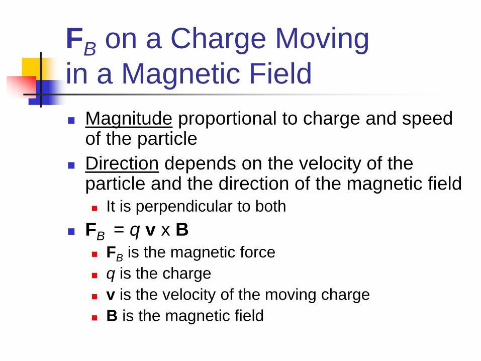
FB on a Charge Moving
in a Magnetic Field
Magnitude proportional to charge and speed of the particle
Direction depends on the velocity of the particle and the direction of the magnetic field It is perpendicular to both
FB = q v x B FB is the magnetic force
q is the charge
v is the velocity of the moving charge
B is the magnetic field
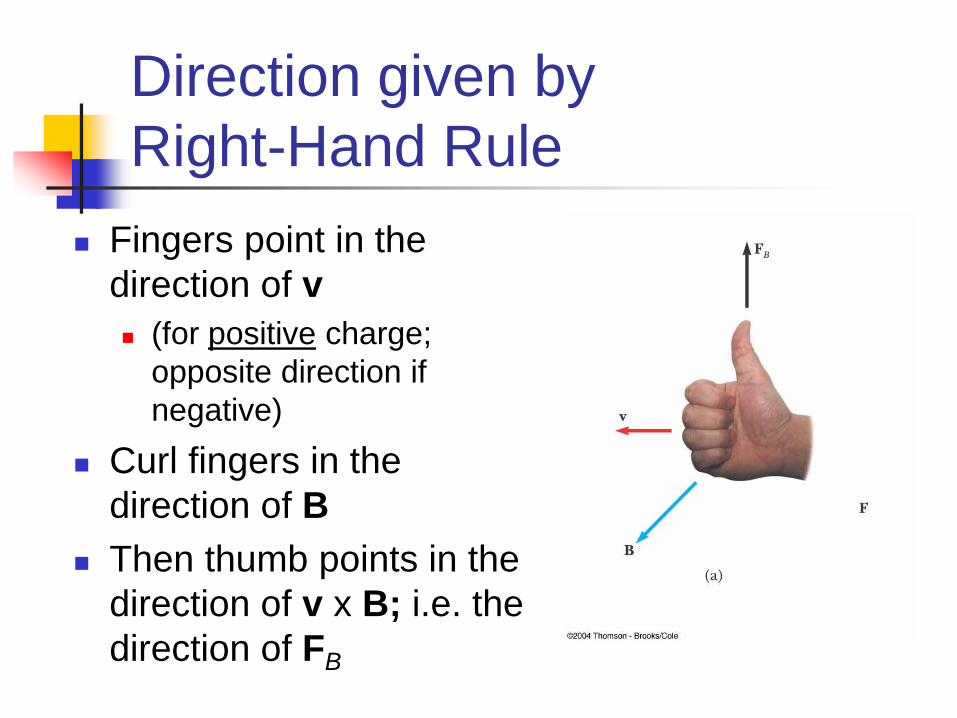
Direction given by
Right-Hand Rule
Fingers point in the
direction of v
(for positive charge;
opposite direction if
negative)
Curl fingers in the
direction of B
Then thumb points in the
direction of v x B; i.e. the
direction of FB

Hall Effect
When the charge carriers are negative, the upper edge of the conductor becomes negatively charged
When the charge carriers are positive, the upper edge becomes positively charged
Sign of Hall voltage, VH, gives the sign of the charges
Biot-Savart Law – Introduction
Biot and Savart conducted experiments
on the force exerted by an electric
current on a nearby magnet
They arrived at a mathematical
expression that gives the magnetic field
at some point in space due to a current

Biot-Savart Law – Set-Up
Measured magnetic field
dB at some point P,
distance r from wire
Wire carrying a steady
current of I
Length element is ds
Biot & Savart found that dB
is proportional to current, I,
length, ds and sin()
is inversely proportional to r2

Observations are summarized in the Biot-Savart law:
Constant o called the permeability of free space o = 4 x 10⁻⁷ T. m / A
The magnetic field is due to the current-carrying conductor
Biot-Savart Law – Equation
d B
0
4
I d s ˆ r
r2
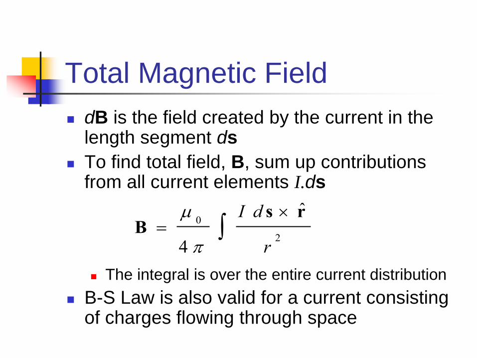
Total Magnetic Field
dB is the field created by the current in the length segment ds
To find total field, B, sum up contributions from all current elements I.ds
The integral is over the entire current distribution
B-S Law is also valid for a current consisting of charges flowing through space
B
0
4
I d s ˆ r
r2

Quick Quiz 30.1
Consider the current in the length of wire shown in the figure
below. Rank the points A, B, and C in terms of magnitude of
the magnetic field due to the current in the length element
shown, from greatest to least.
(a) A, B, C
(b) B, C, A
(c) C, B, A
(d) C, A, B
(e) An equal field applies at all these points.

Answer: (b). Point B is closest to the current element. Point
C is farther away and the field is further reduced by the sin θ
factor in the cross product . The field at A is zero because θ = 0.
Quick Quiz 30.1
d s x ˆ r
B Compared to E, 1
Distance
Magnitude of magnetic field varies as
inverse square of distance from source
Magnitude of electric field due to point
charge also varies as inverse square of
distance from the charge

B Compared to E, 2
Direction
Electric field created by a point charge is
radial in direction
Magnetic field created by a current element
is perpendicular to both the length element
ds and the unit vector
r̂

Source
Electric field is established by an isolated
electric charge
Current element producing a magnetic field
must be part of an extended current
distribution
Need to integrate over entire current
distribution
B Compared to E, 3
B Compared to E, 4
Ends of Field Lines
Magnetic field lines have no beginning and
no end
They form continuous circles
Electric field lines begin on positive
charges and end on negative charges
B for Long, Straight Conductor
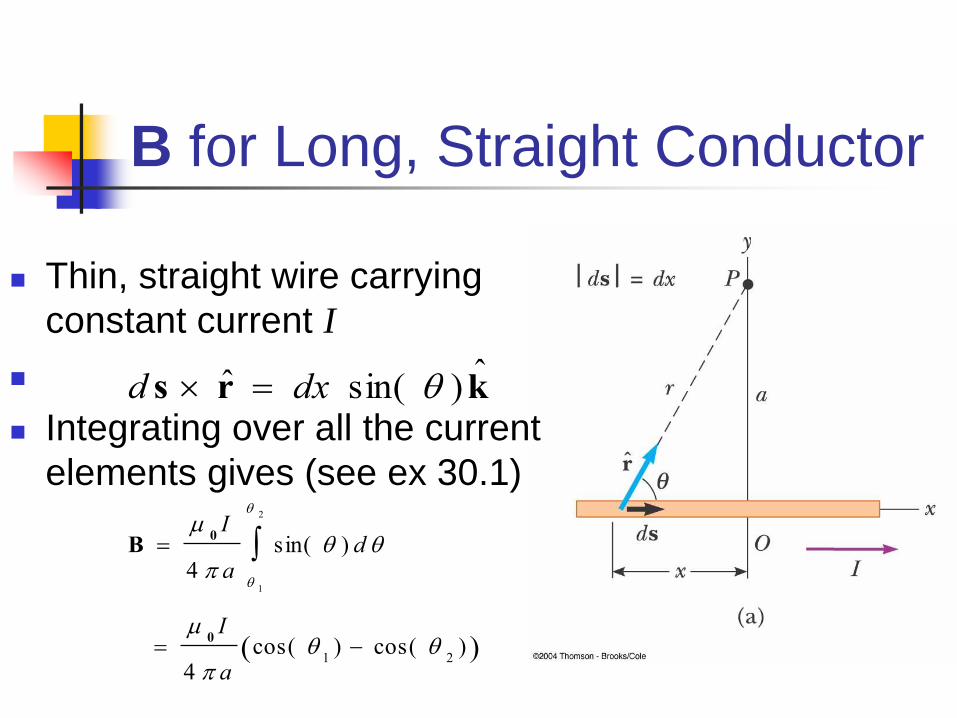
Thin, straight wire carrying
constant current I
Integrating over all the current
elements gives (see ex 30.1)
d s ˆ r dx sin( ) ˆ k
B
0I
4 asin( ) d
1
2
0I
4 acos(
1) cos(
2)

B for a Long, Straight
Conductor, Special Case
For infinitely long,
straight wire
1= 0° and 2= 1
cos(11cos(21
The field becomes
B
0I
2 a
B for a Long, Straight
Conductor, Direction
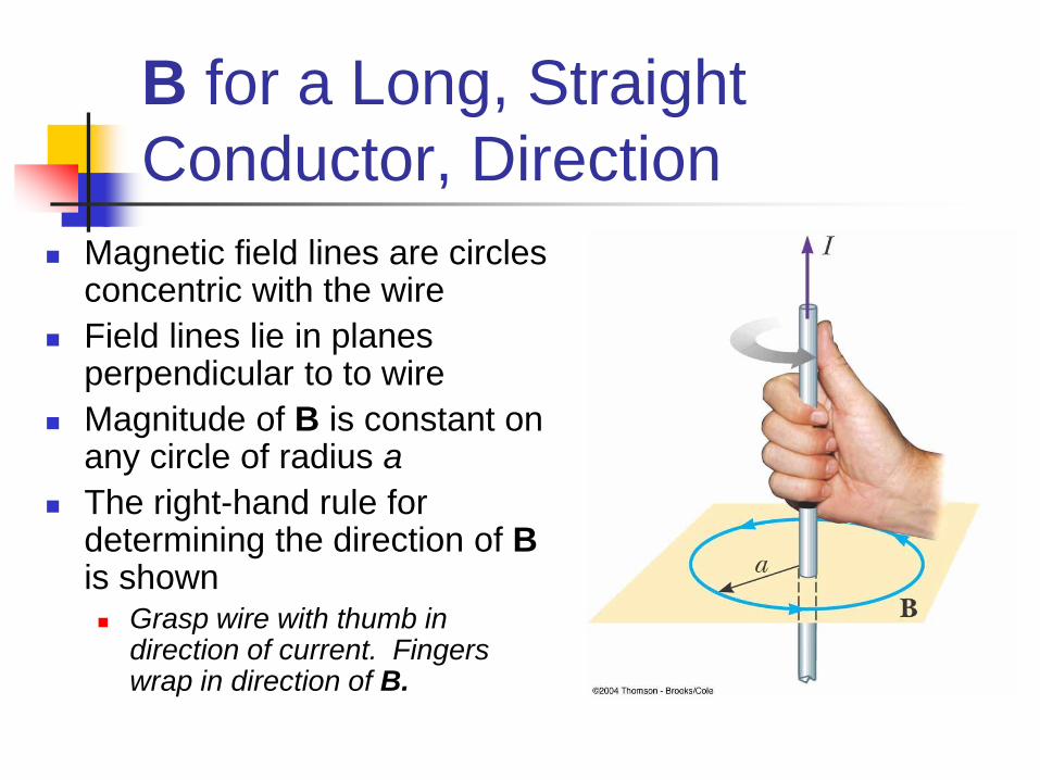
Magnetic field lines are circles concentric with the wire
Field lines lie in planes perpendicular to to wire
Magnitude of B is constant on any circle of radius a
The right-hand rule for determining the direction of B is shown Grasp wire with thumb in
direction of current. Fingers wrap in direction of B.

B for a Curved Wire Segment
What is the field at point O due to the wire segment?
I and R are constants
ds is parallel to r along AA’ and CC’ so we only need to calculate the field from AC.
We find that
in radians
See Example 30.2
B
0I
4 R

B for a Circular Loop of Wire
Put = 2in previous result
This is the field at the centre of the loop
B
0I
4 R2
0I
2 R

Demo Ec10:
Forces between parallel wires
Wires can be made to
attract and repel one
another depending on
the direction of the
current flow through
each wire.

Magnetic Force Between Two
Parallel Conductors
Two parallel wires carrying
steady currents I1 and I2
Field B2 due to the current in
wire 2 exerts a force on wire 1
of F1 = B2 I1 ℓ
However B2 = 0 I2 / 2a, so
F1
0I
1I
2
2 al
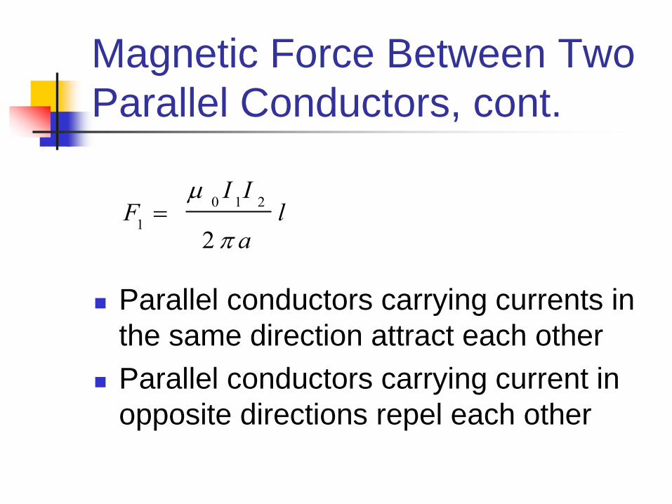
Magnetic Force Between Two
Parallel Conductors, cont.
Parallel conductors carrying currents in
the same direction attract each other
Parallel conductors carrying current in
opposite directions repel each other
F1
0I
1I
2
2 al

Quick Quiz 30.2
For I1 = 2 A and I2 = 6 A in the figure below, which is true:
(a) F1 = 3F2
(b) F1 = F2/3
(c) F1 = F2
Answer: (c). F1 = F2 as required by Newton’s third law.
Another way to arrive at this answer is to realize that
gives the same result whether the multiplication of currents
is (2 A)(6 A) or (6 A)(2 A).
Quick Quiz 30.2
F1
0I
1I
2
2 al

Quick Quiz 30.3
A loose spiral spring is hung from the ceiling, and a large
current is sent through it. The coils move
(a) closer together
(b) farther apart
(c) they do not move at all
Answer: (a). The coils act like wires carrying parallel
currents in the same direction and hence attract one another.
Quick Quiz 30.3
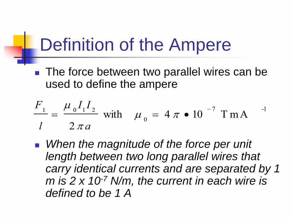
Definition of the Ampere
The force between two parallel wires can be used to define the ampere
When the magnitude of the force per unit length between two long parallel wires that carry identical currents and are separated by 1 m is 2 x 10⁻⁷ N/m, the current in each wire is defined to be 1 A
F1
l
0I
1I
2
2 a with
0 4 10
7 T m A
-1

Definition of the Coulomb
The SI unit of charge, the coulomb, is
defined in terms of the ampere
When a conductor carries a steady
current of 1 A, the quantity of charge
that flows through a cross section of the
conductor in 1 s is 1 C

Magnetic Field of a Wire
Compass can be used to
detect the magnetic field
When there is no current
in the wire, there is no
field due to the current
Needle points towards the
Earth’s north pole
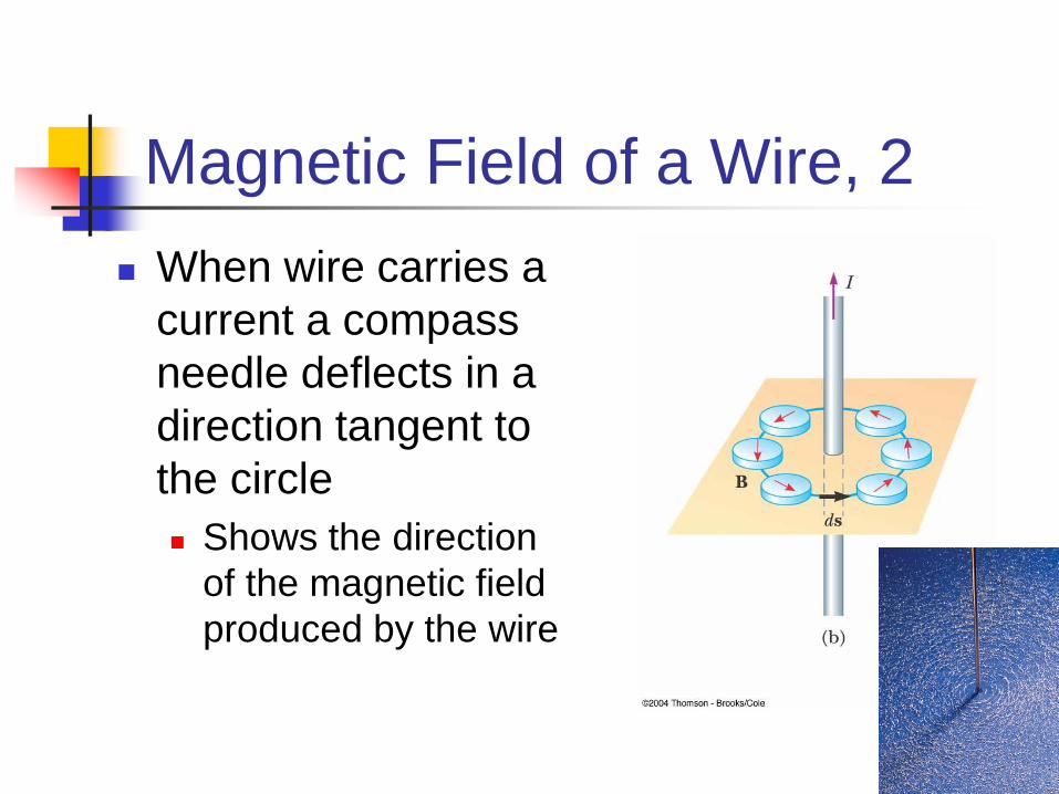
Magnetic Field of a Wire, 2
When wire carries a
current a compass
needle deflects in a
direction tangent to
the circle
Shows the direction
of the magnetic field
produced by the wire

Ampere’s Law
The line integral of B . ds around any
closed path equals µoI, where I is the
total steady current passing through any
surface bounded by the closed path.
B ds 0I
Ampere’s Law, cont.
Ampere’s law describes the creation of
magnetic fields by all continuous current
configurations
Direction: put thumb of right hand in the
direction of the current through loop.
Your fingers curl in the direction you
integrate around the loop.

Quick Quiz 30.4
Rank the magnitudes of for the closed paths in the
figure below, from least to greatest.
(a) a, b, c, d
(b) b, d, a, c
(c) c, d, b, a
(d) c, b, a, d
(e) d, c, a, b
B .d s

Answer: (b). Ampere’s law (above) indicates that the value
of the line integral depends only on the net current through
each closed path. Path b encloses 1 A, path d encloses 3 A,
path a encloses 4 A, and path c encloses 6 A.
Quick Quiz 30.4
B ds 0I

Quick Quiz 30.5
Rank the magnitudes of for the closed paths in the
figure below, from least to greatest.
(a) a, b, c, d
(b) b, c, d, a
(c) b, d, a, c
(d) d, c, a, b
(e) The criteria are
badly chosen in this case.
B .d s
Answer: (e). Ranked from least to greatest, first comes b,
then a = c = d. Paths a, c and d all give the same nonzero
value μ0I because the size and shape of the paths do not
matter. Path b does not enclose the current, and hence its line
integral is zero.
Quick Quiz 30.5
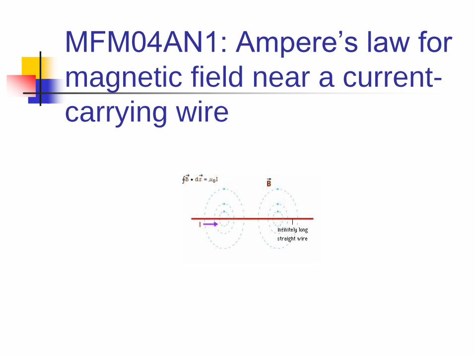
MFM04AN1: Ampere’s law for
magnetic field near a current-
carrying wire

Field Due to a Long Straight
Wire – from Ampere’s Law
Calculate the magnetic
field at a distance r from
the centre of a wire
carrying a steady
current I
The current is uniformly
distributed through the
cross section of the wire

Field Due to Long
Straight Wire
1. Outside of the wire, r > R
2. Inside the wire, current I' at radius r:
B ds B 2 r 0I
B
0I
2 r
I r
2
R2
I , so that
B ds B 2 r 0I
0
r2
R2
I
B
0I
2 R2
r
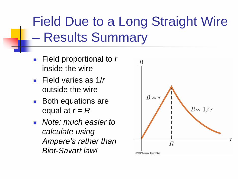
Field Due to a Long Straight Wire
– Results Summary
Field proportional to r
inside the wire
Field varies as 1/r
outside the wire
Both equations are
equal at r = R
Note: much easier to
calculate using
Ampere’s rather than
Biot-Savart law!
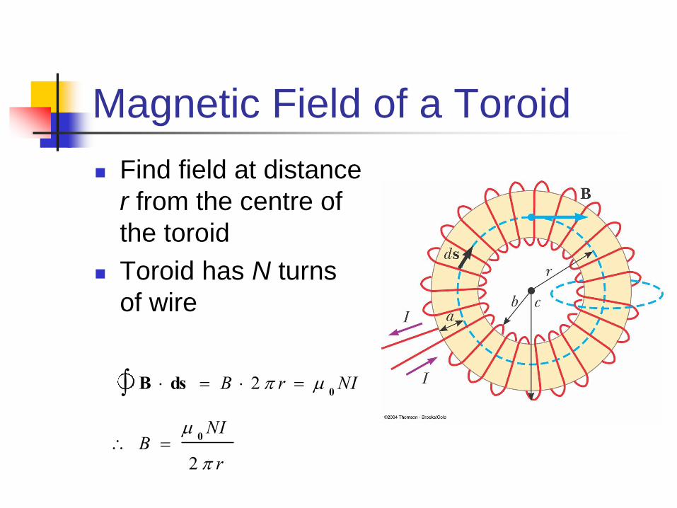
Magnetic Field of a Toroid
Find field at distance
r from the centre of
the toroid
Toroid has N turns
of wire
B ds B 2 r 0NI
B
0NI
2 r

A solenoid is a long wire wound in the form of a helix
Reasonably uniform magnetic field can be produced in its interior.
Here the field lines are approximately parallel
uniformly distributed
close together
Magnetic Field of a Solenoid

Magnetic Field of a Tightly
Wound Solenoid
Field distribution is
similar to a bar magnet
As the length of the
solenoid increases
the interior field becomes
more uniform
the exterior field
becomes weaker
i.e. an “ideal” solenoid

Ideal Solenoid –
Characteristics
An ideal solenoid is
approached when:
turns closely spaced
length much greater
than radius of turns
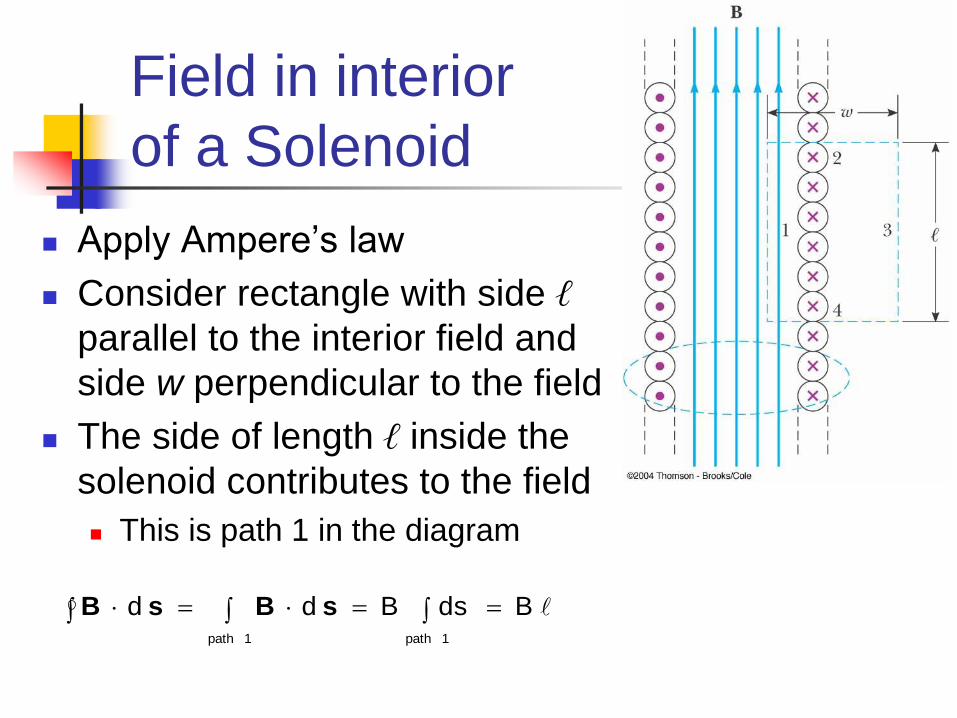
Field in interior
of a Solenoid
Apply Ampere’s law
Consider rectangle with side ℓ
parallel to the interior field and
side w perpendicular to the field
The side of length ℓ inside the
solenoid contributes to the field
This is path 1 in the diagram
BdsBdd
1path 1path
sBsB

Magnetic Field of Solenoid
Total current through the rectangular path equals the current through each turn multiplied by the number of turns
Ampere’s law then gives
n = N / ℓ is the number of turns per unit length
valid only at points near centre of long solenoid
B 0
N
lI
0nI
NIBdo
sB
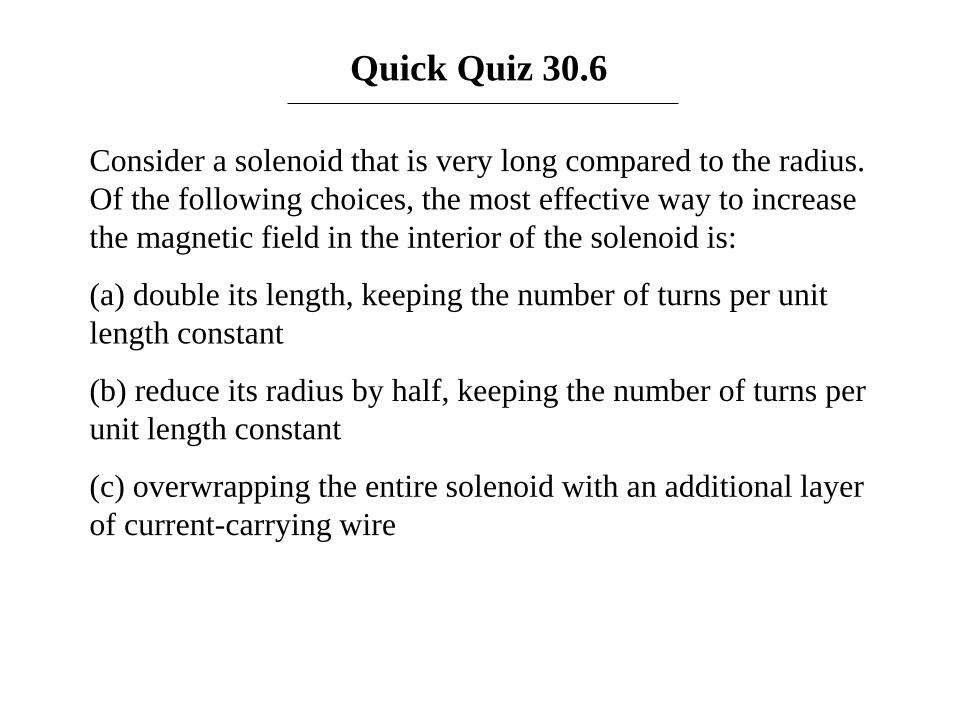
Quick Quiz 30.6
Consider a solenoid that is very long compared to the radius.
Of the following choices, the most effective way to increase
the magnetic field in the interior of the solenoid is:
(a) double its length, keeping the number of turns per unit
length constant
(b) reduce its radius by half, keeping the number of turns per
unit length constant
(c) overwrapping the entire solenoid with an additional layer
of current-carrying wire

Answer: (c). The magnetic field in a very long solenoid is
independent of its length or radius. Overwrapping with an
additional layer of wire increases the number of turns per
unit length.
Quick Quiz 30.6

Ampere’s vs. Gauss’s Law
Integrals around closed path vs. closed surface. i.e. 2D vs. 3D geometrical figures
Integrals related to fundamental constant x source of the field.
Concept of “Flux” – the flow of field lines through a surface.
B ds 0I
E dA q
0

MFM05AN1: Magnetic Flux

Magnetic Flux
Magnetic flux defined in a similar way to electric flux
Consider an area element dA on an arbitrarily shaped surface, and magnetic field B
The magnetic flux FB is
Units T.m2 = Wb Wb is a weber
FB B .d A

Magnetic Flux
through a Plane
Suppose a plane, of area A,
makes an angle with dA
Magnetic flux FB = BA cos
a) When field parallel to plane,
and FB = 0
b) When field perpendicular to
plane, and FB = BA
maximum value

Gauss’ Law in Magnetism
Magnetic fields do not begin or end at any point i.e. they form closed loops, with the number of
lines entering a surface equaling the number of lines leaving that surface
Gauss’ law in magnetism says:
Would not be true if magnetic monopoles were found!
FB B .d A 0
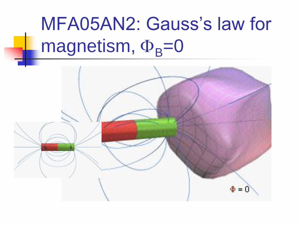
MFA05AN2: Gauss’s law for
magnetism, FB=0
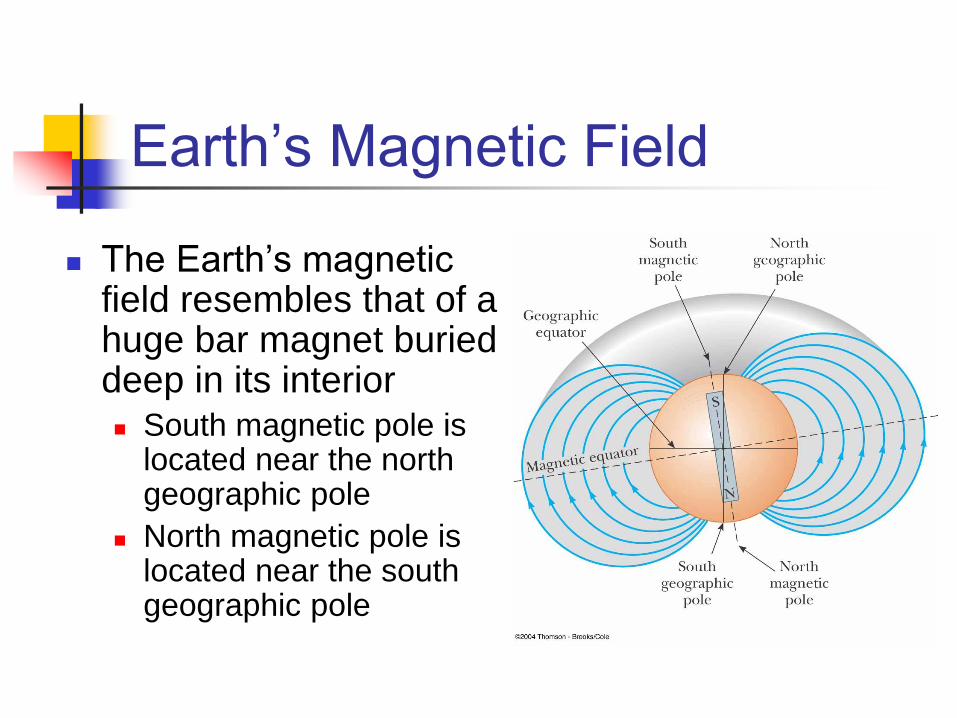
Earth’s Magnetic Field
The Earth’s magnetic field resembles that of a huge bar magnet buried deep in its interior South magnetic pole is
located near the north geographic pole
North magnetic pole is located near the south geographic pole
Dip Angle of
Earth’s Magnetic Field
A compass needle free to rotate vertically as
well as horizontally will point towards the
Earth’s surface
Angle between horizontal and direction of the
magnetic field is called the dip angle
The closer the compass is moved to the magnetic
poles, the farther from horizontal its needle will be
Needle horizontal at equator, with dip angle = 0°
Needle points straight down at south magnetic pole, with dip
angle = 90°

Earth’s Magnetic Poles
Dip angle of 90° near Hudson Bay in Canada
Earth’s south magnetic pole
Dip angle of -90° near Dumont Durville, Antarctica
Earth’s north magnetic pole
The magnetic and geographic poles are not at the
same location
The difference between true north and magnetic north is
called the magnetic declination
Declination varies by location on the Earth’s surface
Source of the Earth’s
Magnetic Field
There cannot be large masses of permanently magnetized materials in Earth’s core since the high temperatures there prevent materials from retaining permanent magnetization
Most likely source of the Earth’s magnetic field is believed to be convection currents in the liquid part of the core It is also likely related to rate of the
Earth’s rotation: dynamo action
QuickTime™ and a
TIFF (Uncompressed) decompressor
are needed to see this picture.

Reversals of the Earth’s
Magnetic Field
The direction of the Earth’s magnetic
field reverses every few million years
Evidence of these reversals are found in
basalts resulting from volcanic activity
The origin of the reversals is not
understood
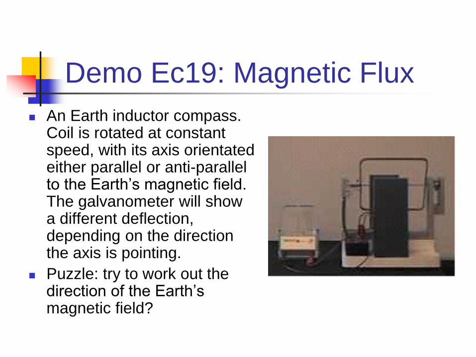
Demo Ec19: Magnetic Flux
An Earth inductor compass. Coil is rotated at constant speed, with its axis orientated either parallel or anti-parallel to the Earth’s magnetic field. The galvanometer will show a different deflection, depending on the direction the axis is pointing.
Puzzle: try to work out the direction of the Earth’s magnetic field?
End of Chapter

Quick Quiz 30.7
In an RC circuit, the capacitor begins to discharge. During
the discharge, in the region of space between the plates of
the capacitor, there is
(a) conduction current but no displacement current
(b) displacement current but no conduction current
(c) both conduction and displacement current
(d) no current of any type

Answer: (b). There can be no conduction current because
there is no conductor between the plates. There is a time-
varying electric field because of the decreasing charge on
the plates, and the time-varying electric flux represents a
displacement current.
Quick Quiz 30.7
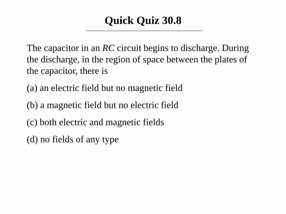
Quick Quiz 30.8
The capacitor in an RC circuit begins to discharge. During
the discharge, in the region of space between the plates of
the capacitor, there is
(a) an electric field but no magnetic field
(b) a magnetic field but no electric field
(c) both electric and magnetic fields
(d) no fields of any type
Answer: (c). There is a time-varying electric field because of
the decreasing charge on the plates. This time-varying
electric field produces a magnetic field.
Quick Quiz 30.8
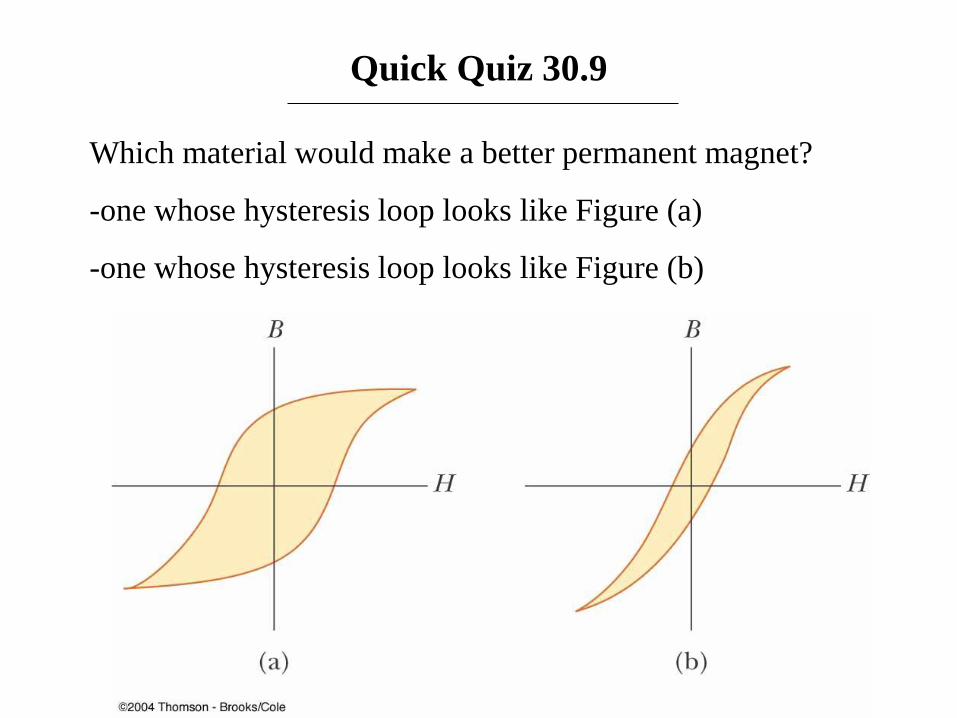
Quick Quiz 30.9
Which material would make a better permanent magnet?
-one whose hysteresis loop looks like Figure (a)
-one whose hysteresis loop looks like Figure (b)

Answer: (a). The loop that looks like Figure 30.32a is better
because the remnant magnetization at the point
corresponding to point b in Figure 30.31 is greater.
Quick Quiz 30.9
Quick Quiz 30.10
If we wanted to cancel the Earth’s magnetic field by running
an enormous current loop around the equator, the current
loop would be directed:
(a) east to west
(b) west to east
Answer: (b). The lines of the Earth’s magnetic field enter the
planet in Hudson Bay and emerge from Antarctica; thus, the
field lines resulting from the current would have to go in the
opposite direction. Compare Figure 30.7a with Figure 30.36.
Quick Quiz 30.10