chapter iii crude oil
TRANSCRIPT

CHAPTER III
Crude Oil
Crude oil is rich in hydrocarbons, mainly paraffins (alkanes), naphthenes (cyclo-alkanes)
and aromatics, with no or very little olefins (alkenes) present. Compounds of the same
skeletal structure, but containing heteroatoms like sulphur, nitrogen, oxygen and metals like
nickel and vanadium, are also present. Sulphur (≤ 5%) and nitrogen (≤ 0.5%) are the
heteroatoms that affect refining the most. In addition to these, corrosion problems may result
from oxygenates in the form of carboxylic acids (≤ 3 mg KOH/g) and salts in the form of
MgCl2 and CaCl2 (≤ 350 μg·g-1). The importance of crude density and distillation
characteristics on refining has also been highlighted.
1. Introduction
Crude oil is a collective term used to describe a hydrocarbon rich mixture of compounds that
is usually found as a subterranean deposit that accumulated over millions of years. The
physical and chemical characteristics of crude oil vary widely from one production field to
another and even within the same field. Colloquially terms like “light”, “heavy”,
“naphthenic”, “paraffinic”, “sweet” and “sour” are used to characterise crude oil in terms of
its boiling range, composition and sulphur content.a These are important properties, because
they have a big impact on the refinery, but it belies the true complexity and diversity of crude
oil. The crude oil composition determines its price and although specific oil types, like Brent
crude, are used as an international measure of oil price, more difficult to refine oils command
a much lower price. The selection and scheduling of crude oil feed to a refinery is a highly
specialised field in its own right,(1) and it directly affects the production economics.
It is important to discuss crude oil properties, because refining technology has been
developed in response to the differences between crude oil properties and final product
specifications. Furthermore, Fischer-Tropsch derived syncrude is different from crude oil in
many respects and it is important to understand these differences, because they relate to the
a The terms “sweet” and “sour” originated as measure of corrosiveness. Crudes with more than 6 μg·g-1 dissolved H2S were considered “sour”, because it led to observable storage tank corrosion. These terms are no longer applicable and it is strictly speaking incorrect to directly relate “sweet” and “sour” to sulphur content.
62

ability of refining technologies to deal with Fischer-Tropsch products. Crude oil will be
discussed in terms of its composition and characterisation in sufficient detail to enable these
objectives to be met.
2. Crude oil composition
The compounds and compound classes present in the lighter fraction of crude, which is
typically the fraction that can be recovered by atmospheric distillation, can be identified by
chromatographic and spectroscopic techniques. The heavier fraction is more difficult to
characterise, because it contains molecular structures with molecular masses that can exceed
10 000 g·mol-1. The heavy fraction is classified based on solubility (Figure 1),(2) with
maltenes being soluble in n-heptane and asphaltenes being soluble in benzene.b The
usefulness of this method of classification is doubtful, since it is unlikely that the chemical
nature of the molecules is adequately captured. The point has aptly been made by Gray(3) that
these heavier fractions are better described as heteroatom species with limited hydrocarbon
character, which tend to associate (almost like Velcro™) making separation by solubility and
precipitation untenable. The popular notion of heavy crude oil molecules being
polycondensed aromatic hydrocarbons (almost like graphite) does not explain the properties
and conversion propensity of heavy crude.
Atmospheric residue
Extract with n-heptane(C7:oil = 30:1)
solubleinsoluble
MaltenesExtract withbenzene
insoluble soluble
AsphaltenesSediment Figure 1. Classification procedure for heavy crude oil fractions (> 360°C boiling fraction).
b The asphaltene content is determined by precipitating the asphaltenes from the benzene solution with a light paraffin. Industrially propane or butane is used, but practice varies and in the USA n-pentane is used. This can lead to differences in the reported asphaltene content and composition of a crude oil. If a light paraffin is used, some heavier paraffins may co-precipitate with the asphaltene fraction, reducing its reported aromatic content.
63

The asphaltene content of crude oil varies from 0.1% to more than 20% depending on
the production field. Asphaltenes contain high concentrations of heteroatoms, like sulphur
and nitrogen, as well as metals, like nickel and vanadium. Due to the heavy nature of the
asphaltenes, their characterisation is mostly done by techniques used in polymer analysis, like
size exclusion chromatography. In refineries equipped with a deasphalting unit, the
asphaltenes are recovered as asphalt and not upgraded to transportation fuel.
Crude oil can be classified by chemical composition, density, viscosity and distillation
characteristics to name a few.(4) The classification system based on composition refers to
only the hydrocarbon nature of oil, namely paraffinic, naphthenic or mixed(5) depending on
the compound class that is dominant.c The other classification systems find utility in giving
an indication of the straight run content of the various distillation ranges, which are important
in determining the product slate that can be expected. This might have been useful in the
past, but it is doubtful whether these classification systems have adequate value for present
refineries, where the true composition of the crude is more important in determining the
refining pathways. The point is aptly made by Speight:(4) “Clearly the use of one physical
parameter, be it API gravity or any other physical property for that matter, is inadequate to
the task of classifying conventional petroleum, heavy oil, and tar sand bitumen.”
2.1. Hydrocarbons
The main hydrocarbon compound classes present are paraffins (alkanes), naphthenes (cyclo-
alkanes) and aromatics, with very little or no olefins (alkenes) present.d The presence of
dienes and alkynes are extremely unlikely.(4) The paraffins found in crude oil tend to have a
high linear hydrocarbon content. This has implications for the fuel quality of straight run
products. Light straight run (LSR) naphtha has a low octane number and can generally not be
included in motor-gasoline without further refining. Conversely, straight run middle
distillates, especially from paraffinic crudes, only needs to be desulphurised (sweetened) to
yield good jet fuel or high cetane diesel.
The naphthenes most frequently encountered in crude oil have 5- or 6-membered
rings and multiple rings may be present. In some cases systems with 4- and 5-membered
c This is ironic, since the point has already been made that crude oil is rich in heteroatom containing compounds. d The presence of olefins in crude oil is a point of dispute. It has been claimed by some that olefins are indeed present, but since such claims generally refer to distilled fractions, cracking cannot be ruled out. There is one exception, however, namely Pennsylvanian crudes, where spectroscopic and chemical methods indicated the presence of olefins (up to 3%). Ref.(4)
64

rings are found, which serve as biochemical markers.e The naphtha range naphthenes make
good reforming feedstock, while middle distillate range naphthenes make good jet fuel.
Mono-, di- and polynuclear aromatics are found in high concentrations in most crude
oils. In the motor-gasoline range, these molecules contribute significantly to the octane
number of straight run products and the gravimetric energy density of jet fuel. However, the
higher homologues are not desirable.
2.2. Sulphur containing compounds
Sulphur is the heteroatom most commonly found in crude oil and the total sulphur is usually
in the range 0.1% to 5% depending on the crudef,(6) and seldom falls outside the range 0.05-
6.0%.(4) It is also the least desirable heteroatom from a transportation fuel perspective. The
distribution of sulphur compounds is not equal over the distillation range and the sulphur
content generally increases with boiling point (Table 1).(7)
Table 1. Distribution of sulphur compounds over the distillation range of a 1.2% sulphur containing crude oil.
Sulphur compound distribution (%) Distillation
range (°C)
Sulphur
content (%) Thiols Sulphides Thiophenes Other †
70-180 0.02 50 50 trace -
160-240 0.2 25 25 35 15
230-350 0.9 15 15 35 35
350-550 1.8 5 5 30 60
>550 2.9 trace trace 10 90 † = Benzothiophenes and heavy sulphides.
The sulphur can be present in an inorganic formg as elemental sulphur, carbonyl
sulphide (COS) or hydrogen sulphide (H2S), or it can be present in an organic form. The
organic classes most often encountered are sulphides, thiols (mercaptans) and thiophenes.
e Hydrocarbons with 4-membered rings give an indication of the crude oil origin, since such compounds are remnants of the structure of the living matter from which it has been derived. f The sulphur content of the crude is related to its origin. For example, on a water-free basis plants contain 0.1-0.4%, molluscs about 0.4% and marine algae percentage levels. There are oil sources with a very high sulphur content, like 14% sulphur crude from Rozel Point in Utah, USA, where it is not clear whether the sulphur only comes from organic material. g Free sulphur is not often present in crude oil, but it can be present as a suspension or it can be dissolved in the oil. H2S is found in the reservoir gas, but the amount dissolved in the oil is typically less than 50 μg·g-1.
65
Thiols have the general formula R-SH and are sulphur equivalents of alcohols. Due to
the presence of the S-H functional group the thiols are acidic in behaviour (much more than
alcohols).(8) They are also extremely malodorous. The thiols are mainly present in the lighter
boiling fractions, but their concentration in crude oil is generally quite low.
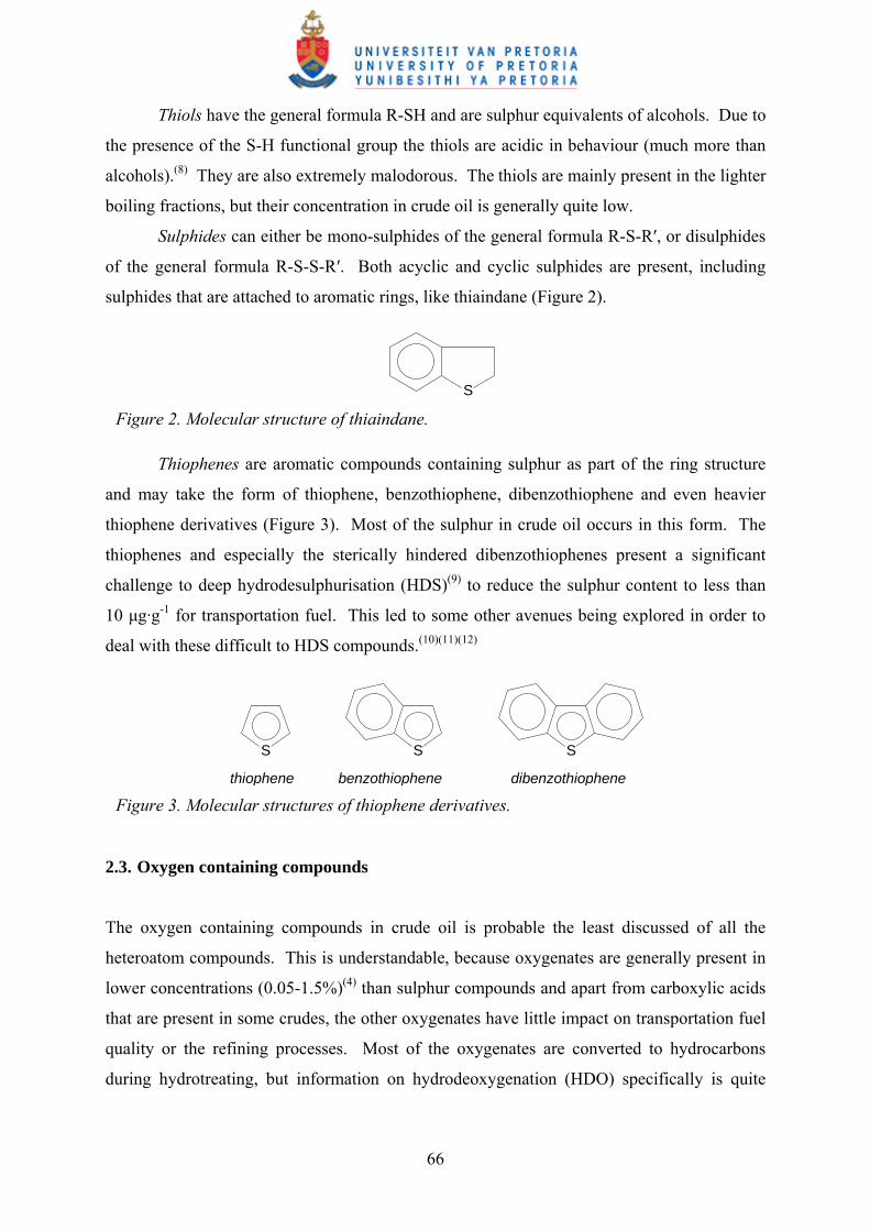
Sulphides can either be mono-sulphides of the general formula R-S-R′, or disulphides
of the general formula R-S-S-R′. Both acyclic and cyclic sulphides are present, including
sulphides that are attached to aromatic rings, like thiaindane (Figure 2).
S Figure 2. Molecular structure of thiaindane.
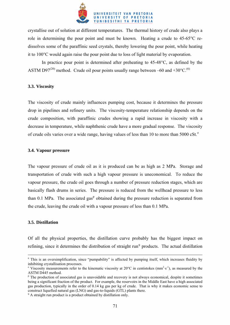
Thiophenes are aromatic compounds containing sulphur as part of the ring structure
and may take the form of thiophene, benzothiophene, dibenzothiophene and even heavier
thiophene derivatives (Figure 3). Most of the sulphur in crude oil occurs in this form. The
thiophenes and especially the sterically hindered dibenzothiophenes present a significant
challenge to deep hydrodesulphurisation (HDS)(9) to reduce the sulphur content to less than
10 μg·g-1 for transportation fuel. This led to some other avenues being explored in order to
deal with these difficult to HDS compounds.(10)(11)(12)
S SS
thiophene benzothiophene dibenzothiophene Figure 3. Molecular structures of thiophene derivatives.
2.3. Oxygen containing compounds
The oxygen containing compounds in crude oil is probable the least discussed of all the
heteroatom compounds. This is understandable, because oxygenates are generally present in
lower concentrations (0.05-1.5%)(4) than sulphur compounds and apart from carboxylic acids
that are present in some crudes, the other oxygenates have little impact on transportation fuel
quality or the refining processes. Most of the oxygenates are converted to hydrocarbons
during hydrotreating, but information on hydrodeoxygenation (HDO) specifically is quite
66

limited.(13) The main oxygenate classes present in crude oil are furanes, phenols, esters and
carboxylic acids.h
Furans are the oxygen equivalent of thiophenes and contains oxygen as part of an
aromatic ring structure (as Figure 3, but with O instead of S).
Phenols are aromatic compounds of the general formula Ph-OH. Although phenol
itself is responsible for transportation fuel elastomer incompatibility, the alkyl derivatives of
phenol are used as oxidation inhibitors(14)(15)(16) in fuel and quite useful at the concentrations
normally present in crude oil.
Esters have the general formula R(CO)OR′ and are considered quite benign in
transportation fuel.i Both aliphatic and aromatic esters can be found in crude.
Carboxylic acids can cause corrosion problems when processing crude at high
temperature.j The acids are not evenly distributed over the whole boiling range, but have a
peak concentration in the 400-450°C range.(6) In lighter cuts some linear aliphatic acids can
be found, but the acids are mostly naphthenic acids (5- and 6-menbered ring cycloalkane
carboxylic acid derivatives) and can include a variety of polycyclic naphthenic acids (Figure
4).(17) The acid number of crudes typically varies from 0 to 3 mg KOH/g.
COOH
R
R
COOH
COOH
R
COOH
R
COOH
R
R
COOH
Figure 4. Some of the naphthenic acids identified in Bohai crude oil.
Although naphthenic acids appear to be the most prevalent type of carboxylic acid,
some crude oil deposits are rich in aliphatic carboxylic acids (>0.1%), such as the crude oil
from the Kutei Basin in Indonesia.(18)
h Amides are also present, which contains the -(C=O)-N< function group. The amides will be discussed with the nitrogen compounds. i The methyl esters of fatty acids in various plant derived oils form the main constituent of biodiesel. j Although crude oil generally does not contain some of the very aggressive short chain aliphatic acids, the heavy naphthenic acids that are present in the crude become quite aggressive at temperatures of 350-400°C, which are often encountered during desalting and lubricating oil production. At such temperatures carbon steel is readily corroded and special alloys are required to deal with acidic crudes.
67

Crude can also contain water, which can be seen as a form of inorganic oxygen. The
water is found partly as dissolved water and partly as emulsions.k The water content can
range from traces to about 2% depending on the crude.
2.4. Nitrogen containing compounds
Nitrogen containing compounds are mostly found in crude oil fractions boiling above 250°C.
The nitrogen content depends on the crude origin, but is generally less than 0.5%, although it
may be as high as 2%.(4) Basic, neutral and acidic nitrogen compounds are present, with the
main nitrogen containing compound classes being amines, amides, pyrroles and pyridines.l,(2)
The basic nitrogen containing compounds reduce the acidity of refining catalysts and are
especially undesirable. Nitrogen compounds may also contribute to gum formation in
products such as domestic fuel oil.(4)
Amines are basic nitrogen compounds and are found as primary (R-NH2), secondary
(R-NH-R′) and tertiary (R-NR′R″) amines.
Amides are acidic nitrogen compounds containing the –(C=O)-N functional group and
are found as both aliphatic and aromatic compounds.
Pyrroles are aromatic compounds containing nitrogen as part of a 5-membered ring
structure and may be present as pyrrole, indole, carbazole and even heavier derivatives of
pyrrole (Figure 5). These are all neutral compounds, despite the presence of the N-H
functionality.m
N
H
N
H
N
H
pyrrole indole carbazole Figure 5. Molecular structures of pyrrole derivatives.
k Such emulsions may be caused by the soaps of the carboxylic acids present in the crude oil, which are known to be surface-active compounds. l Crude oil also contains nitrogen compounds of the porphyrine family, which chelates some metal ions and will be discussed with the metal containing compounds. m This is the result of the lone-pair electrons on nitrogen being delocalised in the aromatic π-cloud and they are consequently not available for sharing with acids. In most of the resonance structures of pyrrole, the nitrogen carries a positive charge.
68

Pyridine and its derivatives like quinoline, isoquinoline and acridine (Figure 6) are
basic nitrogen compounds, with the nitrogen forming part of a 6-membered aromatic ring.
These compounds and their heavier derivatives occur throughout the distillation range.
N N NN
pyridine quinoline isoquinoline acridine Figure 6. Molecular structures of pyridine derivatives.
2.5. Metal containing compounds
The main metal impurities in crude oil are nickel, vanadium and to a lesser extent iron too.(7)
These metals are generally found in the heaviest fractions and end up as deposits in the
residue processing units of a refinery. Some of the metals are trapped in molecules of the
porphyrine family (Figure 7), which act as efficient chelating agents for ions like Ni2+ and
VO+.(2) The metal content is very crude dependent and may vary from less than 1 μg·g-1 to
more than 1000 μg·g-1. However, it should be noted that not all Ni and V are contained in
porphyrine structures.(19)
NN
NN
M
Figure 7. Porphyrine structure for chelating metal ions (M) like nickel and vanadium.
Metals are also introduced in the form of salts of sodium, magnesium and calcium,
usually as the chlorides (NaCl, MgCl2 and CaCl2), but calcium can also be present as the
sulphate or carbonate (CaSO4 and CaCO3).(6) The salt levels vary, with most crudes having a
salt level of between 25-350 μg·g-1 of NaCl equivalent. The major portion of salt is found in
the residues, causing problems in the refinery, like fouling of burners and deterioration of
product quality. Furthermore, magnesium and calcium chlorides start to hydrolyse at 120°C
(Equation 1), a reaction that proceeds quite readily at higher temperatures and that can lead to
severe corrosion in the presence of water.
69

MgCl2 + 2 H2O → Mg(OH)2 + 2 HCl … (1)
There are other metal impurities too, which can be present at low concentrations, like
mercury and arsenic. Impurities like Si, Cu, Pb and P may also be introduced during refining
and recycling of petroleum wastes.(7) Organometallic soaps of Zn, Ti. Ca and Mg may also
be present as surface-active compounds in the oil-water interface.(4)
3. Crude oil physical properties
3.1. Density
The density of crude oil is reservoir dependent and generally falls between 800 and 1000
kg·m-3. It gives an indirect indication of the crude composition, giving rise to the
classification of crude based on density (Table 2),(6) which affects its price. In the oil
industry the density is often expressed in degrees API and the conversion to SI units is given
by Equation 2, where density (ρ) is in units of kg·m-3:
°API = 141.5 / (0.001·ρ) – 131.5 … (2)
Table 2. Crude oil classification based on density at 15°C.
Classification Density range (kg·m-3)
Light crudes < 825
Medium crudes 825-875
Heavy crudes 875-1000
Extra-heavy crudes > 1000
3.2. Pour point
The pour point of crude oil is important from a processing point of view. It essentially
defines the temperature that is required to pump the crude.n Since crude oil is a complex
mixture of compounds, it does not congeal at a specific temperature, but different compounds
70
crystallise out of solution at different temperatures. The thermal history of crude also plays a
role in determining the pour point and must be known. Heating a crude to 45-65°C re-
dissolves some of the paraffinic seed crystals, thereby lowering the pour point, while heating
it to 100°C would again raise the pour point due to loss of light material by evaporation.
In practice pour point is determined after preheating to 45-48°C, as defined by the
ASTM D97(20) method. Crude oil pour points usually range between –60 and +30°C.(6)
3.3. Viscosity
The viscosity of crude mainly influences pumping cost, because it determines the pressure
drop in pipelines and refinery units. The viscosity-temperature relationship depends on the
crude composition, with paraffinic crudes showing a rapid increase in viscosity with a
decrease in temperature, while naphthenic crude have a more gradual response. The viscosity
of crude oils varies over a wide range, having values of less than 10 to more than 5000 cSt.o
3.4. Vapour pressure
The vapour pressure of crude oil as it is produced can be as high as 2 MPa. Storage and
transportation of crude with such a high vapour pressure is uneconomical. To reduce the
vapour pressure, the crude oil goes through a number of pressure reduction stages, which are
basically flash drums in series. The pressure is reduced from the wellhead pressure to less
than 0.1 MPa. The associated gasp obtained during the pressure reduction is separated from
the crude, leaving the crude oil with a vapour pressure of less than 0.1 MPa.
3.5. Distillation
Of all the physical properties, the distillation curve probably has the biggest impact on
refining, since it determines the distribution of straight runq products. The actual distillation
n This is an oversimplification, since “pumpability” is affected by pumping itself, which increases fluidity by inhibiting crystallisation processes. o Viscosity measurements refer to the kinematic viscosity at 20°C in centistokes (mm2·s-1), as measured by the ASTM D445 method. p The production of associated gas is unavoidable and recovery is not always economical, despite it sometimes being a significant fraction of the product. For example, the reservoirs in the Middle East have a high associated gas production, typically in the order of 0.14 kg gas per kg of crude. That is why it makes economic sense to construct liquefied natural gas (LNG) and gas-to-liquids (GTL) plants there. q A straight run product is a product obtained by distillation only.
71

fractions (cuts) that will be produced on the refinery are determined by the refinery design, as
well as the specifications of the fuel types to be produced. Typical cuts are given in Table
3.(6)
Table 3. Typical distillation cuts produced in a refinery.
Description Hydrocarbon range Distillation range (°C)
Gas C3-C4 < 20
Light gasoline C5-C6 20-80
Heavy gasoline C7-C10 80-180
Kerosene C10-C14 160-260
Gas oil C15-C22 260-360
Residue C22+ > 360
Table 4. Distillation characteristics of Arabian Light crude oil, as example to show its relationship to refining requirements.
Property Gas Light
gasoline
Heavy
gasoline
Kerosene Gas oil Residue
Distillation range (°C) < 20 20-80 80-180 180-250 250-370 > 370
Fraction (vol %) 1.7 6.3 17 11.7 21.9 41.4
(mass %) 1.1 4.9 14.8 11 21.9 46.3
Characterisation
Density @ 15°C (kg·m-3) - 659 747 798 854 956
Sulphur content (mass %) - 0.024 0.036 0.16 1.4 3.2
Aromatic content (mass %) - 1.5 14.3 20.7 - -
RON - 60.6 23.5 - - -
Pour point (°C) - - - -48 -6 10
Knowing the volume fractions going to the various distillation columns and refinery
units if a specific crude is to be processed, enables proper scheduling of the crude.r It also
allows an economic analysis of intended crude purchases, by matching the crude oil
r Every refinery unit has a production capacity range, the upper limit set by the maximum operating capacity of the design and the lower limit set by the turndown ratio of the design. The crude oil composition of the feed to the refinery must be such that all refinery units can be operated within their design limitations. The economics of refinery operation is determined by selecting the crude slate in such a way that all units can be operated as close as possible to their maximum capacity given the final product market constraints.
72

characteristics to the market requirements for final products. The cost of processing the
crude oil into transportation fuels has to be factored into these calculations. The straight run
product yield gives an indication of the amount of work that has to be done by the conversion
units in the refinery to produce marketable products (Table 4).(6) This topic will be explored
in much more detail when dealing with crude refinery design in the next chapter.
4. Literature cited
(1) Favennec, J-P. Ed. Petroleum Refining Vol. 5 Refinery Operation and Management;
Editions Technip: Paris, 2001.
(2) Roussel, J-C.; Boulet, R. Composition of crude oils and petroleum products. In
Petroleum Refining Vol. 1 Crude Oil. Petroleum Products. Process flowsheets;
Wauquier, J-P. Ed.; Editions Technip: Paris, 1995, p.1.
(3) Gray, M. R.; Shaw, J. M. Chemical structure of vacuum residue components:
Implications for hydrotreating and hydroconversion; International Symposium for
Advances in Hydroprocessing of Oil Fractions, Morelia, Mexico, June 2007.
(4) Speight, J. G. The chemistry and technology of petroleum, 4ed; CRC Press: Boca Raton,
2007.
(5) Irion, W. W.; Neuwirth, O. S. Oil Refining. In Ullmann’s Encyclopedia of Industrial
Chemistry. 6th Ed; Wiley-VCH: Weinheim, 2001.
(6) Chatila, S. G. Evaluation of crude oils. In Petroleum Refining Vol. 1 Crude Oil.
Petroleum Products. Process flowsheets; Wauquier, J-P. Ed.; Editions Technip: Paris,
1995, p.315.
(7) Heinrich, G.; Kasztelaan, S. Hydrotreating. In Petroleum Refining Vol.3 Conversion
Processes; Leprince, P. Ed.; Editions Technip: Paris, 2001, p.533.
(8) March, J. Advanced Organic Chemistry. 3rd ed; Wiley: New York, 1985, pp.220-222.
(9) Ho, T. C. Deep HDS of diesel fuel: Chemistry and catalysis. Catal. Today 2004, 98, 3.
(10) Shiraishi, Y.; Taki, Y.; Hirai, T.; Komasawa, I. A novel desulfurization process for fuel
oils based on the formation and subsequent precipitation of S-alkylsulfonium salts. 1.
Light oil feedstocks. Ind. Eng. Chem. Res. 2001, 40, 1213.
(11) Shiraishi, Y.; Tachibana, K.; Taki, Y.; Hirai, T.; Komasawa, I. A novel desulfurization
process for fuel oils based on the formation and subsequent precipitation of S-
alkylsulfonium salts. 2. Catalytic-cracked gasoline. Ind. Eng. Chem. Res. 2001, 40, 1225.
73

(12) Takahashi, A.; Yang, F. H.; Yang, R. T. New sorbents for desulfurization by π-
complexation: Thiophene/Benzene adsorption. Ind. Eng. Chem. Res. 2002, 41, 2487.
(13) Furimsky, E. Catalytic hydrodeoxygenation. Appl. Catal. A 2000, 199, 147.
(14) Rosenwald, R. H.; Hoatson, J. R.; Chenicek, J. A. Alkyl phenols as antioxidants. Ind.
Eng. Chem. 1950, 42, 162.
(15) Wasson, J. I.; Smith, W. M. Effect of alkyl substitution on antioxidant properties of
phenols. Ind. Eng. Chem. 1953, 45, 197.
(16) Nixon, A. C.; Minor, H. B.; Calhoun, G. M. Effect of alkyl phenols on storage and
manifold stability of gasolines. Ind. Eng. Chem. 1956, 48, 1874.
(17) Qi, B.; Fei, X.; Wang, S.; Chen, L. Study on distribution and composition of carboxylic
acids of Bohai crude oil in China. Petroleum Sci. Technol. 2004, 22, 463.
(18) Gallup, D. L.; Curiale, J. A.; Smith, P. C. Characterization of sodium emulsion soaps
formed from production fluids of Kutei Basin, Indonesia. Energy Fuels 2007, 21, 1741.
(19) Dunning, H. N.; Moore, J. W.; Bieber, H.; Williams, R. B. Porphyrin, nickel, vanadium,
and nitrogen in petroleum. J. Chem. Eng. Data 1960, 5, 546.
(20) ASTM D97. Standard test method for pour point of petroleum products.
74

CHAPTER IV
Crude Oil Refineries
The history of crude oil refining is used to illustrate how refinery design is influenced by raw
material cost and availability, as well as product specifications and market demand. Four
generations of refinery design are described: Distillation only (1st generation), topping-
reforming (2nd generation), topping-reforming-cracking with vacuum distillation and
optionally visbreaking (3rd generation), and topping-reforming-cracking-visbreaking-
alkylation-isomerisation with vacuum distillation (4th generation). The change drivers,
namely raw materials, profitability and market demands, are resulting in certain trends that
will determine how future crude oil refineries will look. These trends are: Intensification of
residue upgrading, making more hydrogen available, increasing refinery complexity,
addition of renewable fuels and the possibility to produce synthetic fuels. As consequence,
future crude oil refineries will process more olefin intermediates and be more hydrogen rich.
1. Introduction
The purpose of a refinery is to transform a raw material into a more valuable end product that
meets market demands. This is a general definition and holds true for all refineries.a Since
the production of crude oil started in the 1850’s, the market for crude oil derived products
changed dramatically. As a natural consequence, crude oil refineries had to change in design
and complexity to keep up with the changes in the market. As crude became available from
more and more sources, refinery design not only had to cope with changes in products, but
also with changes in feed.
In the middle of the nineteenth century a market was created for kerosene (lamp oil),
when it was realised that it could be used in wick lamps, because it burns with a bright
smokeless flame without leaving a residue.b,(1) The first crude oil refineries consisted of a
a The combination of processes to transform metal bearing ores into metals is also rightly called a refinery. b It is wrong to imply that kerosene was initially made from crude oil, it was not, it was made from coal. In 1850 a process for making “coal oil” was patented in Scotland. This process was developed to augment the dwindling supplies of whale oil. The ability to produce kerosene from oil was demonstrated at Dartmouth college in 1854 and became significant with the increase in oil production in 1859, when Edwin L. Drake started drilling for oil. By 1862 kerosene from oil had completely displaced kerosene from coal.
75

pot-stillc to boil the crude oil so that the middle-boiling fraction (kerosene) could be collected
and sold as lamp oil. Soon afterwards the internal combustion engine was invented,d which
burned gasoline instead of methane (coal gas). This created a market for the light-boiling
fraction of the distillation-only refinery too. These two products, gasoline and lamp oil
(kerosene), were in high demand from 1890 onwards, especially with the boom in the
automobile industry after the introduction of the Ford model T in 1908.e,(2) As a matter of
fact, world consumption of oil doubled every decade since 1880 until the Oil Crisis in 1973
(Figure 1).(3)
10
100
1000
10000
100000
1000000
10000000
1850 1870 1890 1910 1930 1950 1970 1990
Year
Glo
bal o
il co
nsum
ptio
n (k
t/a)
Figure 1. Global oil consumption for the period 1860-1980.
The problem faced by refiners at the beginning of the twentieth century was that the
products obtained from the distillation of crude oil were not in the same ratio as required by
the market. Furthermore, as the automobile manufacturing industry got going and later the
aviation industry too, improvements in engine design required a better quality fuel to deal
c Until 1910 all crude fractionation had been done by batch distillation. Only then did continuous-operating boilers appear. The first true distillation columns were only built in the 1920’s. d Historically it was Germany that played the key part in the development of the automobile, with the invention of the internal combustion engine by August Nikolaus Otto in 1872 and the pioneering work of Gottlieb Daimler and Karl Benz. Both Daimler and Benz realised that gasoline (petrol) would be a better fuel than gas and adapted the Otto-engine for such use. The spark-ignition system and water cooling for automobiles can both be credited to Benz (1885). e Most European automobiles were built for sportsmen and enthusiasts, not for the ordinary man who just needed transport. Henry Ford had the insight to provide transportation for the common man and 15 million Ford model T’s were sold between 1908 and 1927.
76

with the performance requirements of higher compression ratio engines. These two aspects,
namely market requirements and fuel quality, were destined to become a recurring theme in
crude oil refining. Upgrading crude oil by distillation only (a first generation refinery) was
no longer enough and it heralded the start of the second phase in refinery development.
Markets had to be found for the heavier products from crude oil and methods had to
be devised to change the properties of the products to meet the market demands. The second
stage of refinery development is characterised by the introduction of reactive processes to
change the nature of the crude oil. Although the development of refineries, catalysts and the
chemical engineering discipline started off independently, they quickly came together to
create second generation refineries. This period saw the development of many of the key
technologies that are still being used in refineries today (Table 1).(4)(5)(6)(7)(8)(9)(10)(11)
Table 1. Historical development of some key refining technologies.
Year Process Catalyst
1920's Hydrogenation Ni-kieselguhr
1933 Paraffin isomerisation AlCl3
1934 Olefin oligomerisation (CatPoly) Solid phosphoric acid (SPA)
1936 Catalytic cracking (Houdry) Montmorillonite (acidic clay)
1940 Catalytic cracking improved Amorphous silica-alumina (ASA)
1942 Paraffin alkylation HF and H2SO4
1942 Fluid catalytic cracking Amorphous silica-alumina (ASA)
1949 Reforming (Platforming) Pt-Al2O3
1959 Hydrocracking Ni/Mo- Co/Mo- silica-alumina
1964 Zeolite fluid catalytic cracking Faujasite (Y)
1967 Multimetallic reforming Pt/Re- Pt/Ir-Al2O3
1973 Etherification Acidic resin (e.g. Amberlyst 15)
1970's Zeolite based processes ZSM-5, etc.
When the application of compression ignition engines became more widespread,f
markets were found for diesel fuel and fuel oil. Fuel oil started replacing coal as energy
source on ships in the 1900’s.
f Since the development of the compression ignition engine by Rudolf Diesel in 1893, it took some time before its use became widespread. Despite its better thermodynamic efficiency than a spark-ignition engine, a
77

The demand for high-octane aviation gasoline during the Second World War and
transportation fuel in general, also prompted technological advances in crude oil refining.
Yet, crude oil was cheap and despite increasing consumption, prices were low. Many
refineries did not make use of all the technologies that were on offer and the new
technologies that were being developed. Second generation refineries generally used a
simple topping-reforming refinery flowscheme (Figure 2),(12) which sometimes included
visbreakingg too. The refineries that exploited the market for high octane gasoline during the
Second World War, were left long in octane once the demand for aviation gasoline dropped
in the 1950’s.
Naphtha hydrotreaterAtmosphericdistillation
crude oilDistillate hydrotreater
Reforming
Sweetening
naphtha
kerosene
distillate
Acid gas treatmentLPG recovery
residue
gas
propanebutane
gasoline
kerosene
diesel
fuel oil
fuel gas
Figure 2. Topping-reforming flowscheme used by most 2nd generation refineries.
In the early 1970’s crude oil prices were at their lowest, with a barrel of Arabian Light
crude costing only US$ 1.80. This was to change quite dramatically with the Oil Crisis at the
end of 1973,h,(13) when oil prices increased six-fold in a short period of time. In January 1974
compression ignition engine is heavier and more expensive, which initially made its use for automobiles less attractive, but made it very attractive for heavy vehicles and ships. g Visbreaking is a refinery process and the term is used to denote thermal cracking of residues. It is not the same as thermal cracking, which is a process used for the production of short chain olefins. The principle of operation is the same though. h A small number of very large international oil companies informally working together, controlled most of the world’s markets for oil in the 1950’s. By 1959 these companies were under economic pressure from each other and outsiders. They therefore decided to reduce their tax commitments to the producing countries to boost their profits, by posting lower prices for the crude oil on which tax was calculated. The reaction was unexpectedly strong and one of the results was the formation of the Organisation of Petroleum Exporting Countries (OPEC) at the instigation of Venezuela. During the 1960’s internal disagreements amongst member countries failed to result in any coherent collective action, but OPEC survived mostly as a result of the political solidarity felt by the Arab countries. It was this solidarity that caused the production cuts in 1973, since it was seen as a way to get back at the pro-Israel Western world after the Six Day War in 1967 and finally the Yom Kippur War that started on 6 October 1973.
78

a barrel of Arabian Light crude was around US$ 12, with another significant increase that
were to take place at the end of the decade.(3) Since the residue fraction of most crude oils
constitute close to 50% of the total volume of crude oil, the increase in oil price not only
affected the price of white products (motor-gasoline, jet fuel and diesel), but also the price of
fuel oil. This resulted in a drop in the use of fuel oil and a slowdown in the growth of white
product consumption. Refiners now had to produce more white products and less fuel oil,
while light crude oils were becoming scarcer and more costly. This gave rise to third
generation refineries that included significant residue upgrading capacity (Figure 3).(12) Such
refineries typically used topping-reforming-cracking or topping-reforming-cracking-
visbreaking configurations and included a vacuum distillation column for residue
fractionation.
Naphtha hydrotreaterAtmosphericdistillation
crude oilDistillate hydrotreater
Reforming
Sweetening
naphtha
kerosene
distillate
Acid gas treatmentLPG recovery
residue
gas
propanebutane
gasoline
kerosene
diesel
fuel oil
fuel gas
Vacuumdistillation
Fluid catalytic cracking
Visbreaking
Sweetening
Figure 3. Topping-reforming-cracking flowscheme with vacuum distillation and optionally visbreaking of 3rd generation refineries.
79
In the same period, the introduction of unleaded motor-gasoline was lobbied.i This
would remove the 5-7 octane number boost that refiners could rely on by adding tetra-ethyl
lead (TEL) to the motor-gasoline.(14) Just as the Oil Crisis forced refiners to consider crude
as an expensive feedstock from which the production of high value white products had to be
maximised, the need to forgo the use of TEL forced refiners to have a serious look at the
quality of the products being produced. This was not an immediate concern, since lead
phase-out took some time.j Yet, time moved on and in the 1980’s it was realised that taking
out lead was not enough, sulphur content of fuel also had to be reduced.k Deeper
hydrogenation of all cuts not only consumed more hydrogen, but also lowered the octane
number of the motor-gasoline. This set the stage for the development of the next generation
of refineries.
Refinery upgrades and new refineries planned to meet the need for high octane
unleaded, low sulphur motor-gasoline had to modify their naphtha upgrading sections. It was
quickly realised that paraffin quality was the key to meeting the octane demands and that
isomerising C4-C6 paraffins provided a cheap and easy octane boost. It was also realised that
the olefins produced by the high temperature residue upgrading units opened synthetic routesl
for the production of high octane motor-gasoline. Fourth generation refineries (Figure 4),
typical of the 1990’s, used topping-reforming-cracking-visbreaking-alkylation-isomerisation
schemes.(3) These schemes frequently include etherification too. The number and severity of
the hydrotreating operations in a fourth generation refinery are also increased, especially with
respect to the refining of heavier material that is rich in sulphur.
Not all refineries have opted to change with the times and intermediate product
exchange agreements are often used to balance product properties with market demands. For
example, of the 99 refineries in Europe there are still 16 refineries that have not added residue
upgrading capacity(15) and are essentially still 2nd generation refineries.
i The president of General Motors (GM), Mr. Cole, lobbied the introduction of unleaded gasoline. It started with a public announcement at the Society of Automotive Engineers (SAE) on 14 January 1970, which indirectly led to the Clean Air Act Amendments of 1970, signed by Pres. Nixon in November 1970. The distribution network and vehicles requiring unleaded gasoline were ready by end 1974. j The phase-out of lead was a gradual process and in a country like the USA that prefers motor-gasoline to diesel powered vehicles, it took 20 years to complete. By the end of the 1980’s leaded gasoline was essentially gone and by 1996 its use on highways became illegal in the USA. k Ironically the reduction in sulphur was called for in parallel with the phasing out of lead, but to make the introduction of unleaded gasoline a success, its impact was downplayed. l The three main synthetic motor-gasoline technologies based on olefins are alkylation, etherification and oligomerisation. Of these the alkylation of iso-butane with olefins is most often used. Etherification went through a boom-and-bust cycle in the USA for political reasons, but is still widely used in Europe. The use of oligomerisation is less widespread, mainly because it uses two moles of olefin per one mole of product, unlike alkylation and etherification that requires only one mole of olefin per one mole of product.
80

Naphtha hydrotreaterAtmosphericdistillation
crude oilDistillate hydrotreater
Reformingnaphtha
kerosene
distillate
Acid gas treatmentLPG recovery
residue
gas
propanebutane
gasoline
kerosene
diesel
fuel oil
fuel gas
Vacuumdistillation
Fluid catalytic cracking
Visbreaking
Sweetening
C5/C6 isomerisation
Etherification
Alkylation
Residue hydroconversion
Figure 4. Topping-reforming-cracking-visbreaking-alkylation-isomerisation flowscheme, 4th generation refineries.
It will be appreciated that refineries are constantly changing and that they are subject
to the same pressures that shape transportation fuel specifications. Oil refining will therefore
be discussed in general terms, referring to the main separation and conversion processes
needed to produce transportation fuels. This will serve as an introduction to crude oil
refinery design and what factors need to be considered for grassroots refineries, including
some future trends in refinery design.
2. Separation processes
Separation processes are associated with all refining units, but in the present context it refers
to the primary crude oil separation that takes place at the front-end of a refinery (Figure 5).(12)
The first step is desalting, which is mainly a corrosion and fouling prevention measure.
During desalting the crude oil is washed with water and caustic (NaOH) to remove dissolved
salts and to convert acid chlorides, such as MgCl2 and CaCl2, to NaCl (Equation 1) that is a
neutral chloride. This prevents the formation of hydrochloric acid when residual chlorides
enter the refinery.
81

DesaltingCrude oil
Light naphtha (20-80°C)
Liquid petroleum gas (C3-C4)
Heavy naphtha (80-180°C)
Kerosene (180-250°C)
Distillate (250-360°C)
Atmosphericdistillation
Atmosphericresidue
(>360°C)
DeasphaltingDeasphalted oil
Asphalt
(>550°C)
Vacuumdistillation
Vacuum residue
Light vacuum gas oil
Medium vacuum gas oil
Heavy vacuum gas oil
(360-550°C)
Acid gas treatment
Gas recovery section
Fuel gas
Sulphur
Figure 5. Generic separation scheme in crude oil refinery.
MgCl2 (aq) + 2 NaOH (aq) → Mg(OH)2 (aq) + 2 NaCl (aq) … (1)
During this process some naphthenic acids are also converted to their respective
carboxylate salts (Equation 2) and are removed as part of the aqueous effluent.
RCOOH + NaOH (aq) → RCOONa (aq) + H2O … (2)
This can sometimes be problematic though, because the carboxylate salts are surface
active and can form stable emulsions. This hazard is reduced by coalescing and decanting the
water droplets under the influence of an electric field.m,(16)
The main separation step in any crude oil refinery is atmospheric distillation unit
(ADU).n This column fractionates the crude into straight run naphtha, kerosene, distillate
and atmospheric residue. This is a crucial refining step, since it routes the molecules to the
m A field strength in the order of 700-1000 V·cm-1 is typically used. n This is also referred to as the crude distillation unit (CDU).
82

appropriate conversion units in the refinery. The cut point of the atmospheric residue
depends on the prevailing fuel specifications and crude slate used. It is typically set to satisfy
the T90 specification of diesel fuel from the refinery and is usually in the range 360-375°C.
The atmospheric residue is further processed in the vacuum distillation unit.
The cut points of the product fractions from the vacuum distillation unit (VDU)
depend on the refinery configuration. The gas oil or vacuum distillate cuts range from 360-
550°C and are typically used for lubricating oil production, but may also be converted to
lighter cuts in the refinery. The heavy product from the VDU that has a boiling point above
550°C is called the vacuum residue. The vacuum residue contains most of the crude oil
contaminants like metals, salts, heteroatom rich compounds and high molecular weight
polycondensed aromatic structures. The vacuum residue may be further processed in the
refinery, or serve as feed for the last separation process at the front-end of the refinery,
namely deasphalting.
Deasphalting is a liquid-liquid extraction whereby the last of the molecules that can
be refined to white products are extracted from the vacuum residue. Light hydrocarbons, like
propane, butane and pentane are typically used as solvents. The yield of deasphalted oil
increases with increasing molecular weight of the solvent, but its quality decreases, while the
fluidity of the asphalt is likewise decreased with increasing molecular weight of the solvent
(Table 2).(12)
Table 2. Effect of solvent on the quality and yield of deasphalted oil, as illustrated by deasphalting of the vacuum residue (>538°C) of a Heavy Arabian crude.
Type of solvent used for deasphalting Properties
Propane Butane Pentane
Yield (mass %) 32 50 66
Density (kg·m-3) 945 963 985
Sulphur content (mass %) 3.8 4.5 4.9
Nitrogen content (mass %) 0.1 0.2 0.21
Ni+V content (µg·g-1) 6 24 67
Viscosity @ 100°C (cSt) 60 100 250
Dissolved gases and volatile hydrocarbons can be recovered after desalting or
atmospheric distillation. The gas is typically separated into fuel gas, liquid petroleum gas
(LPG) and light naphtha. The gas recovery section is used not only for the straight run gas,
83

but also the gas produced during conversion processes. An important component of the gas
recovery section is acid gas treatment, which entails the removal of hydrogen sulphide (H2S)
from the gas. The H2S is typically dissolved in a solvent from which it can be recovered and
converted to elemental sulphur in a Claus or similar type of unit.(17)
3. Conversion processes
Conversion processes are required to bridge the gap between feed properties and desired
product properties. Numerous refining technologies exist, but for the most part the
conversion processes can be classified under the following headings:
a) Carbon number growth. These are technologies that increase the average
molecular mass of the carbon backbone of the molecule, such as oligomerisation. Due to the
heavy nature of crude oil, there is seldom use for this class of technologies in processing
straight run products, but it is used in upgrading gas from cracking units by processes like
alkylation.
b) Carbon number reduction. These are technologies that decrease the average
molecular mass of the carbon backbone of the molecule, such as cracking. Many residue
upgrading technologieso fall into this category, because they transform molecules with a high
boiling point to lower boiling products.
c) Functionalisation. Technologies that change the functional group to which a
molecule belongs, fall in this category, like hydrodesulphurisation (HDS), reforming and
etherification. One could say that hydrotreating technologies result in defunctionalisation,
but the removal of heteroatom-based functional groups effectively changes the class of
compounds to which a molecule belongs.
d) Rearrangement. This is a special class of technologies that can modify the
structure of a molecule, without changing the carbon number or functional group of the
molecule, like hydroisomerisation and double bond isomerisation.
Some technologies perform more than one function and can be classified into more
than one of these categories. This form of process intensification(18) does not invalidate the
o Residue upgrading technologies are also sub-divided into the classes “hydrogen addition” and “carbon rejection”. A secondary aim of residue upgrading is to enrich the hydrogen content of the lower boiling products. If this can be done by adding hydrogen, like in hydrocracking, which makes it a “hydrogen addition” technology, but hydrogen is a scarce commodity in a crude oil refinery. More often some of the carbon mass of the residue is sacrificed as coke or some other form of carbonaceous product to comparatively enrich the lighter products in hydrogen. Examples of such technologies are fluid catalytic cracking and coking, which make them “carbon rejection” technologies.
84

classification and in such cases the technology is classified according to its main aim. For
example, hydrocracking is mainly a carbon number reduction technology, although it also
results in heteroatom removal. This classification is important, because it describes the
function of the conversion. It comes in handy to describe the type of conversion processes
needed to deal with the various crude oil fractions, without immediately delving into the
details associated with technology selection linked to the specifics of each refinery design.
3.1. Residue upgrading
It is appropriate to start with residue upgrading, since it is a source of lighter boiling fractions
that need to be upgraded with the other straight run products. The upgrading can take two
basic forms, either it aims to reduce the average carbon number of the molecules to be
upgraded as transportation fuels, or it modifies the properties of the products to be used in
non-fuel applications.
3.1.1. Conversion of residue to fuels
Residue upgrading technologies that have carbon number reduction as main objective are
normally high temperature (>350°C) processes:
a) Fluid catalytic cracking (FCC). Typical products from FCC are gas (15-20%),
naphtha in the 20-220°C boiling range (40-50%), light cycle oil in the 220-350°C boiling
range (15-20%), heavy cycle oil and slurry in the >350°C boiling range (15-20%) and coke
(5%).(8)
b) Visbreaking. Typical products from visbreaking are gas (1-5%), naphtha in the 20-
165°C boiling range (5-10%), gas oil in the 165-350°C boiling range (10-25%) and residue in
the >350°C boiling range (60-85%).(19)
c) Coking. Typical products from delayed coking are gas (5-10%), naphtha in the 20-
195°C boiling range (10-25%), gas oil in the >195°C boiling range (30-65%) and coke (10-
35%).(20)
d) Hydrocracking. Typical products from hydrocracking are gas (5%), naphtha in the
20-180°C boiling range (15-20%), kerosene in the 180-250°C boiling range (30-40%), gas oil
in the 250-360°C boiling range (25-45%) and residue in the >360°C boiling range (0-20%).(7)
85

With the exception of hydrocracking, all the other technologies are carbon rejection
processes. They also produce olefins, which is one of the main hydrocarbon classes required
in naphtha upgrading, but that is not present in crude oil.
3.1.2. Non-fuels application of residues
Residues are not necessarily upgraded by conversion technologies. Some of the main non-
fuel related applications of residues rely mostly on separation processes to achieve the
desired product characteristics:(21)
a) Lubricants. There are numerous special lubricant types and applications, but most
lubricants can be classified as either oil or grease. Lubricating oil is generally aliphatic in
nature, with solvent extraction of the aromatics being used to improve the viscosity index and
solvent dewaxing being used to remove linear paraffins to improve the cold flow properties.
Lubricating grease is a semi-solid material that is obtained by dispersing a gelling agent in a
lubricating oil.
b) White oils. This is a term used for highly refined lubricating oils, principally where
the oil has been significantly dearomatised. These white oils were previously made from
light oil cuts treated with oleum to remove the aromatics, but presently deep catalytic
hydrodearomatisation (HDA) is more often used.
c) Paraffins and waxes. These are by-products from solvent dewaxing and are used in
numerous applications ranging from food packaging to polishes and cosmetics.
d) Bitumen. There are many grades of bitumen that differ in hardness and flow
properties. It can be produced as vacuum residue or by deasphalting of vacuum residue. Air
oxidation, typically at temperatures higher than 200°C, is often employed to modify the
structure and to produce hard grades of bitumen. By increasing the oxidation temperature, air
contact time or air pressure the hardness can be increased.(22) Applications of bitumen
include waterproofing, fillers, insulation materials and road binders. Cracked residue does
not make a good feed material for bitumen production.(23)
e) Coke. Although coking has been discussed as a conversion process to produce
fuels, it also produces coke. The quality of the coke determines its application possibilities,
for example graphite, pigments, electrodes or reducing agents in the metallurgical industry.
3.2. Diesel and jet fuel upgrading
86

Diesel and jet fuel have many specification characteristics in common and will therefore be
treated together. The straight run kerosene and distillate have the right carbon number
distribution and mainly requires a reduction in sulphur content and aromatic content
(functionalisation) to meet fuel specifications. This can be achieved by hydrotreating.p
Depending on the crude oil, the product might still contain linear paraffins, which is
good for diesel cetane, but could be detrimental to diesel cold flow properties and cause the
jet fuel to fail the freezing point specification. The linear paraffins can either be modified by
hydroisomerisation (rearrangement), or the linear paraffins can be removed by solvent
dewaxing. The other fuel properties that may be lacking can be fixed by fuel additives.
It is clear that the upgrading of crude oil derived straight run kerosene and distillate is
not complicated. Since the requirements for jet fuel and diesel are almost the opposite of that
required for motor-gasoline, it is anticipated that naphtha upgrading will be much more
involved.q
3.3. Naphtha and gas upgrading
The upgrading of naphtha and gas to motor-gasoline is unit-wise by far the most intensive
refining operation. The main adjustments that have to be made to the properties of the fuel
are related to the sulphur content and octane number (functionalisation and rearrangement),
as well as the average molecular mass when dealing with gas (carbon number growth).
Getting rid of the sulphur is not difficult, since naphtha range material contains mostly
mercaptans and other easy to remove sulphur containing compounds, which can be removed
by mild hydrotreating or sweetening. Meeting the octane number specification is more
difficult. Crude oil derived straight run naphtha typically has a low octane number (LSR
from Arabian Light crude has a RON of about 60 and the heavy naphtha has a RON of less
than 25)(16) and increasing the octane number requires a complex refinery scheme.
The main sources of octane are aromatics and oxygenates (ethers and alcohols), but
the volume of these compounds are limited by motor-gasoline specifications. Roughly half
p Hydrotreating to meet diesel fuel specifications will automatically ensure that the mercaptan specification of jet fuel is met. Previously this would not necessarily have been the case and the kerosene cut would have to go through a sweetening process. q It may seem that the increased refining complexity required for motor-gasoline production compared to diesel fuel production is another reason to nudge the market in the direction of increased diesel fuel use. Surprisingly, from a refining perspective this is not true. Catalytic reforming is the main source of refinery hydrogen and is linked to motor-gasoline production. Furthermore, since transportation fuels are sold by volume, motor-gasoline effectively commands a higher price than diesel fuel on account of its lower density.
87

of the motor-gasoline has to be paraffinic and it is the quality of the paraffins in the fuel pool
that determines the refining needs (as discussed in Chapter II). As a rule of thumb, the
required minimum octane number of the paraffins can be calculated by a simple formula
(Equation 3) based on the octane specification (RONspec) and the volume fractions (Vi) and
octane numbers (RONi) of the various compound classes:
RONparaffin ≥ [RONspec – (RON·V)aromatic – (RON·V)oxygenate – (RON·V)olefin]/Vparaffin ... (3)
Most modern crude oil refineries use catalytic reforming.r The reformer is not only
the main source of aromatics for the motor-gasoline, but also the main source of hydrogen in
the refinery. The octane number of aromatic rich reformate can be manipulated by varying
the severity of the operating conditions of the reforming unit, but in practise reformate
generally has a RON of 96-102, with an aromatic content of around 70%.(9)
Not all refineries have etherification units and with present pressure on fuel ethers in
the USA, many refiners are forced to use ethanol instead. Nevertheless, ethanol has a RON
of 120,(24) while the typical fuel ethers have a slightly lower octane number. Olefin
oligomerisation, which typically yields a RON of about 96, is practised in some refineries,
but FCC derived olefins are more often used for etherification and aliphatic alkylation.
Using Euro-4 specifications as reference, aromatics can be blended to 35%, olefins to
18% and ethers and alcohols to 10-15%. If typical, realistic refinery values are substituted
into Equation 3,s the paraffin RON required to make 95 octane motor-gasoline can be
calculated for scenarios with and without oxygenates and olefins (Equations 4-7):
RONparaffin ≥ [95 – (98·0.5)aromatic – (120·0.1)oxygenate – (96·0.15)olefin]/(0.25)paraffin ≥ 79 ... (4)
RONparaffin ≥ [95 – (98·0.5)aromatic – (120·0.1)oxygenate – (0)olefin]/(0.4)paraffin ≥ 85 ... (5)
RONparaffin ≥ [95 – (98·0.5)aromatic – (0)oxygenate – (96·0.15)olefin]/(0.35)paraffin ≥ 91 ... (6)
RONparaffin ≥ [95 – (98·0.5)aromatic – (0)oxygenate – (0)olefin]/(0.5)paraffin ≥ 92 ... (7)
It is clear that even when oxygenates and olefins are added to the fuel, some paraffin
upgrading is required to increase the octane number of the straight run naphtha. The
r A catalytic reformer will typically not be found in refineries that do not produce on-specification motor-gasoline as a final product. In such refineries hydrogen is produced by other means, for example steam reforming of methane. s Since reformate is not a pure aromatic stream, but contains about 70% aromatics at a RON of 98, 50% of the motor-gasoline can be made up of reformate without violating the 35% maximum aromatic specification.
88

following upgrading pathways can be considered, assuming that a source of olefins is
available from residue conversion units in the refinery:
a) Etherification. Depending on the branched olefins being available and the
preferred alcohol, the typical fuel ethers produced are 2-methoxy-2-methylpropane (MTBE,
methyl tertiary butyl ether), 2-ethoxy-2-methylpropane (ETBE, ethyl tertiary butyl ether) and
2-methoxy-2-methylbutane (TAME, tertiary amyl methyl ether). These ethers all have a
RON in the range 115-118.(24) It is also possible to directly etherify light FCC gasoline,(25)(26)
yielding a product with a calculated blending RON of 110.(27) However, it has been shown
that most C6 and heavier ethers have poor octane numbers, unless the source olefin is highly
branched.(28)
b) Olefin oligomerisation. There are various technologies available for olefin
oligomerisation,(29) but when the focus is on unhydrogenated motor-gasoline, the octane
values from many processes fall in a narrow band around RON 92-97 and MON 79-82.
Olefinic motor-gasoline is therefore close to octane neutral, albeit somewhat MON
constrained.
c) Aliphatic alkylation. The alkylation of iso-butane with olefins to produce alkylate,
is often used as a source of high octane paraffins; RON 92-97 and MON 90-94.(30)(31)(32)
Although the product is highly desirable, current commercial processes are all based on either
sulphuric acid (H2SO4), or hydrofluoric acid (HF). Much effort has been spent on the
development of more environmentally friendly solid acid catalysed processes, but with
limited success.(33) It can be argued that aliphatic alkylation is essential to meet the
requirements for high octane paraffins, but environmental concerns keep looming in the
background.
d) Hydroisomerisation. The skeletal isomerisation of paraffins in the C4-C6 range is
often practised. Butane isomerisation typically provides a source of iso-butane for aliphatic
alkylation when it is used in the refinery, while hydroisomerisation of LSR (C5-C6) is
routinely employed to produce an isomerate with RON 78-92, depending of the recycle
configuration of the technology.(10) The hydroisomerisation of C7 and heavier fractions is
actively researched, but has met with little success.(34)(35)
It can therefore be said that all naphtha and gas upgrading sections of a crude oil
refinery has a hydrotreater to remove sulphur and reformer to produce aromatics. In addition
to these units, one or more paraffin upgrading units needs to be present, namely aliphatic
alkylation and hydroisomerisation, with optionally etherification and olefin oligomerisation.
89

An external source of alcohols is required to produce motor-gasoline blends that require
oxygenates.
4. Future crude oil refineries
4.1. Change drivers in crude oil refining
Based on the historical development of crude oil refineries, it does not take a huge leap of
faith to predict that crude oil refineries will continue to change. The drivers for change are
inherent to the purpose of a refinery, namely to transform a raw material into a more valuable
end product that meets market demands. These are:
a) Crude oil availability and cost. Although it is unlikely that crude oil will run out in
the short term, it is a finite resource and some of the more sought after types of crude oil may
become scarcer more quickly. This underpins two threats to a refinery, namely the
availability and the cost of the raw material.
b) Refinery capital and operating cost. To turn the raw material into a more valuable
product, the market must be willing to buy the product at a higher price than the cost of
upgrading it. To process cheaper more readily available raw materials (lower quality heavy
crudes), will require capital to be invested in residue upgrading units and result in an increase
in the operating cost. Refiners are also under pressure to keep their environmental footprint
small and processing heavier crudes is environmentally speaking a move in the wrong
direction. The decision to modify a refinery to deal with cheaper difficult crudes, is therefore
not such a clear-cut investment decision.(36) Furthermore, there is a rising cost associated
with environmental conservation and the refinery upgrades needed to keep within legislated
emission levels.t,(37) The underlying threat is that more efficient, more environmentally
friendly or even alternative technologies for the production of transportation fuel may come
along to undermine the profitability of investments in refining infrastructure. Conversely
there is the threat that in times of high profit, governments might impose a “windfall” tax on
refiners, as has indeed happened in the past.(38)(39)
c) Market demands. To sell transportation fuel, the fuel must comply with the fuel
specifications that have been changing to require increasingly refined products. This places
strain on the refiner, because the environmental concerns giving rise to more stringent fuel
90

specifications, translate into a larger environmental footprint of the refinery. This reality is
not always appreciated by the politicians and the lawmakers. Furthermore, the market for
refined products is not homogeneous and grows at different rates in different regions. In
general market demand for fuel oil is decreasing and market demand for white products are
increasing,(3) but this says nothing about the substructure of white product demand. Product
price also affects the overall market demand and may selectively suppress the use of some
fuel types when the price is too high, or stimulate their demand when the price is low. This
gives rise to fears about over-investment in refining capacity, as well as under-investment in
refinery flexibility to deal with market swings.
4.2. Changes in crude oil refining
The impact of the change drivers will be seen both in refinery design, as well as in the
transportation fuel industry. In refineries, effects will most likely be seen in the following
areas:(40)
a) Residue upgrading. More efficient residue upgrading is key to refining economics.
This is driven by the lower demand for heavy products like fuel oil and the price differential
between expensive light crude oils and cheap heavy crude oils.(3)(12)(41) The need for
molecules from residue upgrading units, especially olefins,(42) is also becoming more
apparent with the need for high octane paraffinic blending components for motor-gasoline
production. This further emphasises the importance of residue upgrading in future. The
nature of the residue upgrading capacity that is added has one natural side-effect, namely that
it influences the motor-gasoline to distillate ratio produced by the refinery. In Europe this is
a serious concern and may cause the significant swing from motor-gasoline to diesel to slow
down and reach a natural refinery driven equilibrium.u,(15) Any technology breakthrough in
residue upgrading technology, for example novel technology to improve or supersede FCC,
will have a tremendous impact on future crude oil refinery flowschemes.
b) Hydrogen production. The drive to produce more ultra low sulphur transportation
fuels will increase the need for hydrogen in the refinery. The increase in hydrogen demand is
exacerbated by the lowering of the maximum aromatics content in fuel, which decreases the
t In many European countries the cost of compliance to environmental legislation increased between 400-2500% from 1985 to 1993. u In Europe many refiners are already having difficulty meeting diesel fuel demand and quality. This problem is most acute in refineries having FCC’s (57 refineries), which represent 76% of the European refining capacity. It is not clear to what extent the political landscape will change to cope with this challenge.
91

hydrogen production in the refinery. Additional hydrogen will also be required if residue
upgrading increasingly employs hydrogen addition, rather than carbon rejection.(12)(43) This
may necessitate investment in on-purpose hydrogen production units.(3) At this stage
hydrogen production is costly and chances of a “hydrogen economy” bleak,(44) but advances
in technology may make refineries more hydrogen rich in future.
c) Refinery complexity and cost. As fuel specifications drive the fuel composition
further away from the crude oil composition, more units will be required to make final
products. This has implications for refinery complexity and cost, increasing the minimum
refinery size that makes economic sense. To offset the cost, refineries may increasingly opt
for co-generation of power,(3) as well as to co-produce chemicals. With increasing focus on
residue upgrading and hydrogen production, chemicals like propylene from FCC(45) and
aromatics from reforming(46) are natural choices for co-production.
d) Renewable fuel. If the inclusion of bio-derived components in transportation fuel
becomes mandatory, it will be impossible for a crude oil refinery to produce on-specification
fuel with only crude oil as raw material. At present, most fuels that include a bio-derived
component are only blends, but there are already investigations dealing with possible co-
processing.v
e) Synthetic fuel. The need for hydrogen in a refinery can be addressed by investing
in on-purpose hydrogen production, which may entail gas reforming (water-gas shift). This
would not only make hydrogen available, but could potentially also make synthesis gas (H2 +
CO) available to the refinery. If this happens, crude oil refineries may in future become
integrated with synthesis gas based synthetic fuel technologies, such as Fischer-Tropsch(48)
and Syngas-to-methanol.(49) The benefit of CO2 capture to enhance oil production(50) in
addition to the use of Fischer-Tropsch technology to produce fuels, have also been
advocated.(51) Although it should be noted that the possibility of using CO2 for enhanced oil
recovery, is very location specific. Furthermore, gasification technology could be a
convenient sink for excess coke production from residue upgrading by delayed coking, since
the coke can be employed as gasifier feedstock. This approach has previously been explored
in the Exxon Donor Solvent (EDS) process for direct coal liquefaction.(52) The EDS process
v It is interesting to speculate on the political ramifications of this situation. Big oil companies may want to buy into agriculture, which is arguably then an essential part of their business. Since bio-fuels are subsidised, the oil companies would be subsidised, an issue that is already boiling up with the 2007 Tyson-ConocoPhillips deal. According to this deal, a “renewable” diesel fuel will be produced from animal fat by co-processing the animal fat with crude oil derived hydrocarbons in a thermal depolymerisation (cracking) unit.
92

was combined with the gasifier section from an Exxon Flexicoker(20) to convert the coal
residue into hydrogen, which is needed for coal liquefaction.
4.3. Future crude oil refineries
Translating trends in crude oil refining into a futuristic flowscheme is fraught with the same
obstacles encountered in devising any generic refinery flowscheme. Views on future crude
oil refineries should therefore not be seen as a concrete entity, but rather as an expression of
philosophy, with very different pictures emerging.
Figure 6. Future crude oil refinery concept developed along traditional lines. (This figure has been reproduced directly from Ref.(12) and is copyright protected).
A fairly traditional approach is presented by Heinrich from the Institut Français du
Pétrole (Figure 6).(12) The intensity of residue upgrading and the need for additional
hydrogen in the refinery is reflected in the addition of a hydrocracker and partial oxidation
unit. Although it is not explicitly indicated, the partial oxidation unit is coupled with some
form of syngas-to-methanol technology, making the refinery self-sufficient in terms of
methanol for etherification. A lot of emphasis has been placed on etherification for the
production of high octane oxygenates, a view that is questionable in USA context, but
probably still valid for Europe. The appearance of an olefin oligomerisation unit is
93

interesting, since it implies a much more olefin rich refinery. The increase of olefins is a
consequence of the intensification of residue upgrading, but also a means to reduce the
hydrogen requirements.w Of the five trends identified in the previous section, only the
inclusion of renewable fuel is not reflected and it can be argued that it shouldn’t be, since it
does not require co-refining, only blending.
Figure 7. Future crude oil refinery concept based on environmental friendliness of the refining units. (This figure has been reproduced directly from Ref.(42) and is copyright protected).
A much more radical approach, focussing on the environmental impact of the refining
units, is presented by Chen from ExxonMobil (Figure 7).(42) The flowscheme is not always
technology specific, with technology classes being grouped together, like olefin upgrading
and deep hydroprocessing. This hides the increased complexity of the refinery. The intensity
of residue upgrading and hydrogen production is reflected by the use of a thermal cracker,
fluid coker, high temperature FCC and gasifier. The gasifier also enables the production of
synthetic fuels by other means, like Fischer-Tropsch. In general there is a clear fuel synthesis
focus and “the heart of this new scheme resides in olefin upgrading technologies”. The
w If C8 is taken as a representative carbon number for motor-gasoline, the ability to include octenes (C8H16) from olefin oligomerisation, rather than octanes (C8H18) in the fuel pool, saves about 10% hydrogen for that fraction.
94

exclusion of aliphatic alkylation and hydrocracking is interesting. The exclusion of the
former is understandable from an environmental perspective and the latter is excluded purely
as result of the proposed configuration. Again four of the five refining trends are embodied
in the flowscheme, with only renewable fuel not being shown.
The consequence of the trends in crude oil refining is that future crude oil refineries
will become more hydrogen and olefin rich and have the capacity to integrate synthesis gas
based synthetic fuel. It is also expected that peak oil production, that is likely to be reached
soon,(53)(54) will have a significant impact on transportation fuel production. The emergence
of hybrid crude oil refineries that co-process alternative materials like tar sands or coal might
fundamentally change the way in which crude oil refining is approached in future.
5. Literature cited
(1) Tugendhat, C.; Hamilton, A. Oil. The biggest business; Eyre Methuen: London, 1975.
(2) Larsen, E. A history of invention; J. M. Dent & Sons: London, 1969.
(3) Edern, Y. Introduction. In Petroleum Refining Vol.3 Conversion Processes; Leprince, P.
Ed.; Editions Technip: Paris, 2001, p.1.
(4) Ipatieff, V. N.; Corson, B. B.; Egloff, G. Polymerization, a new source of gasoline. Ind.
Eng. Chem. 1935, 27, 1077.
(5) Thomas, J. M.; Thomas, W. J. Principles and practice of heterogeneous catalysis; VCH:
Weinheim, 1997.
(6) Ancillotti, F.; Fattore, V. Oxygenate fuels: Market expansion and catalytic aspect of
synthesis. Fuel Process. Technol. 1998, 57, 163.
(7) Billon, A.; Bigeard, P.-H. Hydrocracking. In Petroleum Refining Vol.3 Conversion
Processes; Leprince, P. Ed.; Editions Technip: Paris, 2001, p.333.
(8) Bonifay, R.; Marcilly, C. Catalytic cracking. In Petroleum Refining Vol.3 Conversion
Processes; Leprince, P. Ed.; Editions Technip: Paris, 2001, p.169.
(9) Martino, G. Catalytic reforming. In Petroleum Refining Vol.3 Conversion Processes;
Leprince, P. Ed.; Editions Technip: Paris, 2001, p.101.
(10) Travers, C. Isomerization of light paraffins. In Petroleum Refining Vol.3 Conversion
Processes; Leprince, P. Ed.; Editions Technip: Paris, 2001, p.229.
(11) Bartholomew, C. H.; Farrauto, R. J. Fundamentals of industrial catalytic processes, 2nd
ed.; Wiley: Hoboken, 2005.
95

(12) Heinrich, G. Introduction to refining. In Petroleum Refining Vol. 1 Crude Oil. Petroleum
Products. Process flowsheets; Wauquier, J-P. Ed.; Editions Technip: Paris, 1995, p.365.
(13) Odell, P. R. Oil and world power. Background to the Oil Crisis, 3rd ed.; Taplinger: New
York, 1975.
(14) Colucci, J. M. Fuel quality – an essential element in vehicle emission control; Proc.
ASME Internal Combustion Engine Division Technical Conference: Long Beach, CA,
2004.
(15) Hutcheson, R. Refining transportation fuels; Gasoline and diesel fuel technology:
Oxford Princeton programme 8793, 2006.
(16) Chatila, S. G. Evaluation of crude oils. In Petroleum Refining Vol. 1 Crude Oil.
Petroleum Products. Process flowsheets; Wauquier, J-P. Ed.; Editions Technip: Paris,
1995, p.315.
(17) Legrand, C.; Castel, J. Acid gas treatment. In Petroleum Refining Vol.3 Conversion
Processes; Leprince, P. Ed.; Editions Technip: Paris, 2001, p.575.
(18) Stankiewicz, A.; Moulijn, J. A. Process intensification. Ind. Eng. Chem. Res. 2002, 41,
1920.
(19) Leprince, P. Visbreaking of residues. In Petroleum Refining Vol.3 Conversion
Processes; Leprince, P. Ed.; Editions Technip: Paris, 2001, p.365.
(20) Swindell, R. Coking. In Petroleum Refining Vol.3 Conversion Processes; Leprince, P.
Ed.; Editions Technip: Paris, 2001, p.381.
(21) Thiault, B. Characteristics of non-fuel petroleum products. In Petroleum Refining Vol. 1
Crude Oil. Petroleum Products. Process flowsheets; Wauquier, J-P. Ed.; Editions
Technip: Paris, 1995, p.271.
(22) Chelton, H. M.; Traxler, R. N.; Romberg, J. W. Oxidized asphalts in a vertical pilot
plant. Ind. Eng. Chem. 1959, 51, 1353.
(23) Jones, D. S. J. The non-energy refineries. In Handbook of petroleum processing; Jones,
D. S. J., Pujadó, P. R. Eds.; Springer: Dordrecht, 2006, p.483.
(24) Travers, P. Olefin etherification. In Petroleum Refining Vol.3 Conversion Processes;
Leprince, P. Ed.; Editions Technip: Paris, 2001, p.291.
(25) Wyczesany, A. Chemical equilibria in the process of etherification of light FCC gasoline
with methanol. Ind. Eng. Chem. Res. 1995, 34, 1320.
(26) Rihko, L. K.; Krause, A. O. I. Etherification of FCC light gasoline with methanol. Ind.
Eng. Chem. Res. 1996, 35, 2500.
96

(27) Torck, B.; Convers, A.; Chauvel, A. Methanol for motor fuel via the ethers route. Chem.
Eng. Progress 1982, 78:8, 36.
(28) Marais, Z-M. Sintese en evaluering van ‘n reeks petrolmengkomponente. (Engl. Trans.
“Synthesis and evaluation of a series of petrol blending components.”); MSc dissertation,
University of the Orange Free State, 1991.
(29) Leprince, P. Oligomerization. In Petroleum Refining Vol.3 Conversion Processes;
Leprince, P. Ed.; Editions Technip: Paris, 2001, p.321.
(30) Corma, A.; Martínez, A. Chemistry, catalysts, and processes for isoparaffin-olefin
alkylation. Actual situation and future trends. Catal. Rev.-Sci. Eng. 1993, 35, 483.
(31) Joly, J.-F. Aliphatic alkylation. In Petroleum Refining Vol.3 Conversion Processes;
Leprince, P. Ed.; Editions Technip: Paris, 2001, p.257.
(32) Nielsen, R. H. Alkylation for motor fuels. Process Economic Program report 88B; SRI:
Menlo Park, 2001.
(33) Weitkamp, J.; Traa, Y. Isobutane/butene alkylation on solid catalysts. Where do we
stand? Catal. Today 1999, 49, 193.
(34) Chica, A.; Corma, A. Hydroisomerization of pentane, hexane, and heptane for improving
the octane number of gasoline. J. Catal. 1999, 187, 167.
(35) Okuhara, T. Skeletal isomerization of n-heptane to clean gasoline. J. Jpn. Petrol. Inst.
2004, 47:1, 1.
(36) Snow, N. Are upgrades to process lower-quality crudes worth the investment? World
Refining 2004, 14:8, 52.
(37) Irion, W. W.; Neuwirth, O. S. Oil Refining. In Ullmann’s Encyclopedia of Industrial
Chemistry, 6th Ed; Wiley-VCH: Weinheim, 2001.
(38) Anon. Windfall folly costs. Oil Gas J. 2005, 103:45, 21.
(39) Gavin, J. Big oil battles the taxman. Petroleum Economist 2006, 73:1, 18.
(40) De Klerk, A. Fuels Refining in the Future; Sasol Technology, Technology Conference:
Sasolburg, South Africa, 2005 (13 Oct).
(41) Higgins, T. Residual fuel will continue to drive refining needs. World Refining 2004,
41:2, 4.
(42) Chen, N. Y. An environmentally friendly oil industry? Chem. Innov. 2001, 31:4, 10.
(43) Ancheyta, J.; Speight, J. G. Eds. Hydroprocessing of heavy oils and residua; CRC: Boca
Raton, 2007.
(44) Wald, M. L. Questions about a hydrogen economy. Sci. Am. 2004, 290:5, 40.
97

(45) Walther, M. Refinery sources will fill the future 'propylene gap'. Oil Gas J. 2003, 101:4,
52.
(46) Bjacek, P. Petchem producers must adopt proactive strategies to improve profits. Oil Gas
J. 2002, 100:32, 52.
(47) Sarma, A. K.; Konwer, D. Feasibility studies for conventional refinery distillation with a
(1:1) w/w of a biocrude blend with petroleum crude oil. Energy Fuels 2005, 19, 1755.
(48) Steynberg, A. P.; Dry, M. E. Fischer-Tropsch technology; Elsevier: Amsterdam, 2004.
(49) Tijm, P. J. A.; Waller, F. J.; Brown, D. M. Methanol technology developments for the
new millennium. Appl. Catal. A 2001, 221, 275.
(50) Moritis, G. CO2 injection gains momentum. Oil Gas J. 2006, 104:15, 37.
(51) Peckham, J. Gasification looking like strong contender for clean fuels, power. World
Refining 2004, 14:8, 54.
(52) Mitchell, W. N.; Trachte, K. L.; Zaczepinski, S. Performance of low rank coals in the
Exxon Donor Solvent Process. Ind. Eng. Chem. Prod. Res. Dev. 1979, 18, 311.
(53) Daya, A. Cassandra of the energy industry. Petroleum Economist 2006, 73:3, 48.
(54) Petzet, A. World oil production to peak in 15-25 years, AAPG told. Oil Gas J. 2007,
105:16, 50.
98