chapter-ii literature review -...
TRANSCRIPT

28
CHAPTER-II
LITERATURE REVIEW
The growing complexities of radar and communication systems have created a need
for antennas capable of forming multiple simultaneous beams. The main component
of this antenna is a BFN, capable of generating multiple, independent and highly
directional beam patterns, using a single linear antenna array. Developed in 1963 by
Rotman and Turner, the Rotman lens is a passive structure capable of driving arrays
containing hundreds of broadband elements. Rotman lens was the name given after its
invention by an American scientist Sir Walter Rotman who contributed a lot in the
field of Radar and antenna design. His inventions were Rotman lens, sandwich wire
antenna and trough wave guide.
In this chapter the overall detailed literature survey and review of research and
technical papers regarding the design and development of the Rotman lens antenna
from time to time has been carried out. The observations and the proposals given by
the contributors in the area to improve the performance of the lens along with the
concluding remarks have been summarized.
2.1 INTRODUCTION
Due to the rapid advancement in wireless communication system the need for
efficient antenna design with good radiation capability, multiple simultaneous beams
and small size is required (FCC, 2002). Research work to improve the antenna design
for obtaining desired goals has been carried out by various researchers in the last few
decades. Smart antennas with wide scanning angle capabilities have emerged as a
result of continuous effort in making an efficient antenna design. Modern day cutting
edge applications like Radar and Satellite communication require antennas with wide
scanning angle capabilities and better performance over a broad frequency range
(Archer, 1984). Antennas used in various applications should satisfy some common
criteria, i.e. small size, light weight and good radiation properties.
To appreciate the significance of the most popular of the constrained lens
architectures, the Rotman lens antenna, it is necessary to provide a review of the
constrained lens development. To fully understand the concept of these complicated

29
and complex lenses, the basic history behind the development of the microwave must
be dealt with. The constrained lens arrays are special groups of BFN’s. They share
some similarities with the dielectric lenses and reflector antennas on one hand and
with the antenna arrays on the other. Their function is to form beams in multiple
directions which correspond to the location of the feed antennas at the focal surface.
The name constrained comes from the fact that a wave incident on one face of the
array does not necessarily obey Snell’s law when passing through the lens array; it is
instead constrained to follow the transmission line paths (Gagnon, 1989). Unlike
dielectric lenses or reflector antennas, lens arrays do their collimation (transmission)
and focusing (reception) discretely, using antenna arrays.
The design procedure of a microwave lens demonstrates how a lens model can be
simulated. A significant number of studies include the overall development in the
design of the lens. In 1950s, J. Ruze came with the concept of wide angle metal plate.
Eventually, after gradual development the microwave lens emerged as a BFN and was
used in many evolving applications (Smith, 1983; Dong and Zaghloul, 2010). Due to
the advancement in the materials science and several fabrication technologies, new
implementations of the microwave lenses using waveguide, striplines and microstrip
came into subsistence (Tao and Delisle, 1997; Hall et al.2000; Zayed et al.2004).
Multiple beam arrays for mm wave indoor communication also picked up when the
concept was presented by Delisle et al. Many important advancements have been
made to reduce the overall phase error of the lens. New design parameters as well as
the shape of the lens have been analyzed to see the overall performance of the lens
(Sinjjari and Chowdhury, 2008). Due to the overall development in the antenna
pattern; a maximum radiation could be displayed in the direction of the influencing
signal. This was the basis of microwave beamforming.
To understand the significance of the most popular of constrained lens architectures,
the Rotman lens, it is necessary to provide a review of the same. The history and
development of the microwave lens acquaints with various designs that researchers
presented to improvise the working. The review of the past development and
emerging applications of microwave lens forms the basis of newly proposed designs.
The Rotman lens is of the bootlace lens type, a constrained optical scanner as given
by Hansen in 1998. In this chapter, the origins of the bootlace lens along with the

30
brief history of its design and development have been dealt. Beam forming was
achieved by designing a lens for equal path-lengths between a point source and the
desired EM wave front. These lens antennas have been the true-time delay devices.
The beam forming operation is entirely mechanical. Because of its features they are
inherently frequency independent. However, a limitation on the achievable frequency
bandwidth depends on the components used to fabricate the lens antenna, such as the
feed port. Contour integral analysis of planar components was given by Mittal et al. in
2003.
Development of the bootlace lens, work done in the improvisation of side lobes
developed in the main beam of the lens, Microwave BFN, reduction of the phase
error, insertion of the dielectric material, mutual coupling between the ports, the shape
of the lens and general trends in the design of the Rotman lens have been surveyed.
The evolution of constrained lenses from dielectric lenses and reflector antennas have
been presented in the following sections.
2.2 THE BOOTLACE LENS
In 1957, H. Gent presented an extra degree of freedom to the constrained lens of Ruze
developed in 1950. The Gent's lens did not require the waveguide plates to meet the
antenna aperture at the same height. For this reason, these parallel conducting plates
were replaced by flexible transmission line, such as coaxial cable. As these flexible
lines of transmission resembled the laces of the boots, Gent’s lens was named as
bootlace lens. This new way of connecting a lens device has many advantages. The
size and space of the array element is no longer confined to the parallel plate
waveguides of the lens. Initially, the lens and the radiating aperture were the part of
the same structure but now they have been split into two different components,
namely the lens and the antenna array. For this reason, the bootlace lens is not
categorized as a metal-lens antenna, although it has been adapted from it. In 1946,
W. E. Kock, introduced the concept of metal-lens antennas. In the 1960's there had
been a large demand for the bootlace lens due to its true-time delay and simultaneous
beam forming capability. It was cheaper and more robust over its counter-part; the
Butler matrix. The concept of multibeam antenna array was given in 1973 by Archer
et al. and was further improvised in 1984. In 1986, J. A. Kong developed the lens

31
design by making use of the optical ray theorem which stated that the optical path-
lengths between two constant phase fronts were equal. As the technology progressed,
the main advantage of the bootlace lens remained its simplicity as provided in 2005
by Archer and Maybell. The popular bootlace lenses and its implementation have
been discussed below.
2.2.1 Popular Bootlace Lens Types and Implementations
The earliest constrained lens was the R-2R lens, as given by Brown in 1950 and 1969,
where the inner and outer surface of the lens and the outer radius was twice the inner
radius. The R-2R lens concept originated during wartime. The shape provided perfect
collimation for the feed points on the focal arc. However, due to the amplitude
asymmetry between beams, the side lobe level increased. The problem was overcome
by W. Rotman and R.F. Turner in 1963. They shared design equations for the trifocal
bootlace lens. The lens designed by Rotman and Turner applied refocusing of the
focal arc as derived by Ruze in 1950. Rotman and Turner introduced Rotman lens
phenomena. The Rotman lens is the most popularly implemented bootlace lens
device. This gave a “near optimum" design for a least phase error distribution.
Trifocal lenses are generally called as Rotman lenses, whether they use the concept of
refocusing or no. The path in the metal lens configuration is formed using parallel
metal plates. The formation of the lens contour depends on the thickness of the lens
and the desired refractive index. The focal arc is a circle, centered on the origin that
passes through the two focal points. A correction to wide angle microwave for line
source applications was developed by Leonakis in 1986. The aberrations due to the
path length associated with a metal lens can be large and are dependent on the design
of the lens. To combat aberrations, a refocusing of the lens is carried out. The lenses
take different forms depending on how the equations describing the Ruze lens have
been applied.

32
The Figure 2.1 shown below represents four types of Ruze lens designs based on the
lens requirement. The choice of lens configuration has a significant effect on the
refocused focal arc, size of the lens and the weight. The Figure 2.1 (a) represents a
constant thickness but requires significant refocusing to achieve optimal performance.
Figure 2.1(b) shows variable thickness and does not require refocusing, but results in
a very heavy lens. This weight is reduced using zoning as shown in Figure 2.1 (c) by
stepping the lens using multiples of the wavelengths. Figure 2.1 (d) uses a flat front
face and requires limited refocusing.
Figure 2.1 Ruze lens configuration (Ruze J., 1950)
Until the bootlace lens was reported by Gent in 1957, constrained lenses were treated
merely as a convenient refractive medium. The bootlace lens changed this perception
by considering constrained lenses as arrays of antennas connected by lengths of
transmission line. The first antenna array forms the input contour and the second is
referred to as the lens contour. The lens is then driven by individual antennas placed
along the focal arc.

33
The bootlace aerial demonstrated that constrained lenses could be implemented using
a wide variety of transmission line types connecting several types of radiators. The
use of non-dispersive transmission lines, coaxial or parallel wire cable, for example,
makes very broadband lens systems practical. Microstrip or Stripline
implementations, combined with a high dielectric substrate, allow very compact
constrained lens designs as given by Maybell et al. in 2005. An LTCC based folded
Rotman lens antenna for phased array applications was designed by Tudosie and
Vahldieck in 2006.
The bootlace lens is similar to the Ruze lens. The three degrees of freedom available
in the metal lens was supplemented by a fourth in the bootlace lens given by Gent.
The four degrees of freedoms were:
1. The shape of the input contour or antenna array.
2. The shape of the output contour or lens contour.
3. The length of the transmission line connecting corresponding antenna elements and
the ports.
4. The relative positions of the antenna elements and ports on the antenna array and
the lens contour respectively.
In contrast to the lens topologies described so far, the R-2R and R-KR lens makes use
of a uniformly spaced circular antenna array instead of a linear antenna array. The R-
2R geometry is unique because it is perfectly focused for all beam angles; however, it
is limited by a maximum field-of-view of 180 degrees. The R-KR lens is able to scan
through 360 degrees, but has no perfect focal points (Clapp, 1984).
2.3 THE SIDE LOBES OF ANTENNA ARRAYS FED BY MULTIPLE BEAM
FORMERS
For the reception of the signal, the role of the beam former is to combine the received
signals of the antenna elements and deliver it to the single output port. These signals
are added with phase shifts that increases from one element to the next and results in

34
an antenna radiation pattern with single beam pointing in a certain direction in the
space. In 1997 Rausch and Peterson designed a millimeter wave Rotman lens. This
was based on the contour integral. A mm wave Rotman lens that operated between the
frequencies of 33-37 GHz was designed. Various parameters were analyzed.
Maximum side lobe levels ≤ - 30 dB was obtained. In 1998, Rausch designed a
conventional antenna array using Rotman lens similar to a linear array which
consisted of a large number of array ports. The frequency of operation was 30-40
GHz and lower side lobes were achieved. To achieve lower side lobes, attenuator was
used between the array ports and antenna elements to produce a Taylor amplitude
taper across the array. But the use of an attenuator reduced the gain of the whole
antenna system. Tekkouk et al., in 2012 gave the concept of folded Rotman lens
antenna which had multibeam capability in SIW technology at 24 GHz to improve the
side lobes. Broadband beam forming was given by Jafari et al. 2013, which intended
to reduce side lobes.
2.4 SIDE WALL ABSORPTION ON THE PRINTED ROTMAN LENS
Microstrip Rotman lens is the multiple beam forming device for antenna arrays. The
research investigated factors limiting the performance of microstrip lens compared to
parallel plate lenses. New techniques for sidewall absorption and lens port pointing
were identified and demonstrated. In 1983, Smith presented a new design approach
for reduction of side wall absorption, which was one of the performances limiting
parameter. Smith emphasized the flexibility of designing large scan angle Rotman
lens by applying small subtended beam regions. The proposal of the effect of side
wall absorption was given by Musa and Smith in 1989. They proposed the design of
microstrip Rotman lens port design, which had a parallel plate region of height <λ/2
filled with dielectric material, r =10.5. Large numbers of array ports were connected
to the array elements via micro-strip and coaxial lines. They proposed that if the lens
line lengths were equal, as that of the Ruze Lens then only two foci were available
and if the line lengths varied as that of the Rotman design, then three foci would be
available, which considerably reduced the side wall absorption. Numerical techniques
were provided in 1999 by Peterson and Rausch for the analysis of various lenses.
Investigations and measurements of termination of sidewalls of microstrip lens
antenna was given by Dong and Zaghloul in 2009. The traditional design equations do

35
not enumerate the purview of the sidewall that connects the lens focal port to array
port. They specify the port location but do not specify port width. The parameters,
especially side lobe level, side wall absorption, phase error and insertion loss affects
the overall performance of the lens.
2.5 PHASE ERROR IMPROVEMENT
In 1984 an upgraded design method for Rotman lens antenna was proposed by
Takashi Katagi et al. They used a new design parameter to design the Rotman lens.
The use of this variable reduced the phase error for large array length. This method
made it possible to design small and low loss Rotman lens antenna. Katagi also
suggested that the shape of the beam contour is not necessarily a circular arc. By
varying the original design equations, the shape of the lens and the radiation angle
resulted in the low phase error. In 2005, Rappaport and Zaghloul carried out a review
of the concept of design of multifocal bootlace lens. It was observed that the Rotman
or bootlace offers more degree of freedom that helped in realizing multiple focal
points. The lens has three radiating structures which are the feed array on one side of
the lens and radiating array on the other side of the lens. The degree of freedom can
be achieved with the location of the feed element and the lengths of the transmission
lines between the receiving and the radiating ports. A modified approach to design
Rotman (1963) type multiple beam forming lens was proposed by Singhal et al., in
2003. The path length error at the wavefront was calculated. The error obtained was
compared to the conventional approach. 2D EM field analysis of the lens obtained by
the modified approach and by the conventional approach lens was carried out using
the contour integral method. The results obtained for both the lenses were
comparable. In 2009 Uyguroglu et al. introduced a new concept of feed curves such
that the phase error reduced. The method was based on having almost zero error
positions on the radiating array for each feed curve point and eventually he made use
of the PSO optimization technique to reduce the phase error.
2.6 DEVELOPMENT OF BEAM FORMING TECHNIQUES
Multiple beam antennas allow a number of beams to be simultaneously transmitted
and received from a single array aperture. The multiple-beam systems are used in
many applications such as in electronic counter measures, satellite communications,

36
multiple-target radars, and in adaptive nulling (Skolnik and Meads, 2001). Lens beam
formers have fixed beam angles, while beam-widths change with frequency. The
simplest BFN is simply N fixed phase or time delay feeds connected to each element
by an N-way power divider. The power divider causes a 1/N signal reduction making
preamplifiers necessary to maintain the signal to noise ratio. This type of network is
practical, only for small numbers of beams and elements. A Butler network is a
simple network using components which can be easily implemented in strip-line or
microstrip; however the layout is difficult due to conductor crossovers. The ideal
Butler matrix is the analogue circuit equivalent of the Fast Fourier transforms
(Uyguroglu et al., 2014). The Rotman lens (Rotman and Turner 1963) is one of the
most functional linear array feed networks because of its excellent aberration
characteristics and frequency-invariant beam pointing. The Rotman lens achieves path
length errors in an order of magnitude smaller than that of dual focal point lens
(Smith, 1982). The excellent aberration characteristics is a product of an additional
focal point made possible by the extra degree of freedom offered by the bootlace lens.
This improvement in performance satisfies the low phase error requirements of wide
apertures forming narrow beams. For this reason the Rotman lens has become the
accepted standard when driving linear antenna arrays. In 1995, Peik and Heinstadt
designed the multiple beam microstrip array fed by Rotman Lens. In 1996 Lee and
Valentine applied the heterodyne technique to the Rotman lens to reduce the size of
the BFN for airborne antenna operating at L- band (1.4 GHz). An alternative to the
above is the use of the RF heterodyne method. This was accomplished by mixing two
higher frequencies in Rotman without dielectric loading. Tao and Delisle, in 1997
designed the lens for indoor communications. They suggested that multi beam
antenna has the potential to produce numerous beams in distinctive directions from
the same aperture, which is different from electronically scanned array which has one
port for each beam. The capability of the system can be increased by reducing
interference.
Further, in 2002, Chan suggested a Rotman lens feed network to generate a hexagonal
lattice of multiple beams. A rectangular lattice with identical row of column boards of
Rotman lenses to feed a hexagonal array of radiating elements was developed. Very
little work has been done on 2D stack of Rotman lens to produce multiple overlapping
beams that are scanned in both Azimuthal and elevation directions (Dong et al.,
37
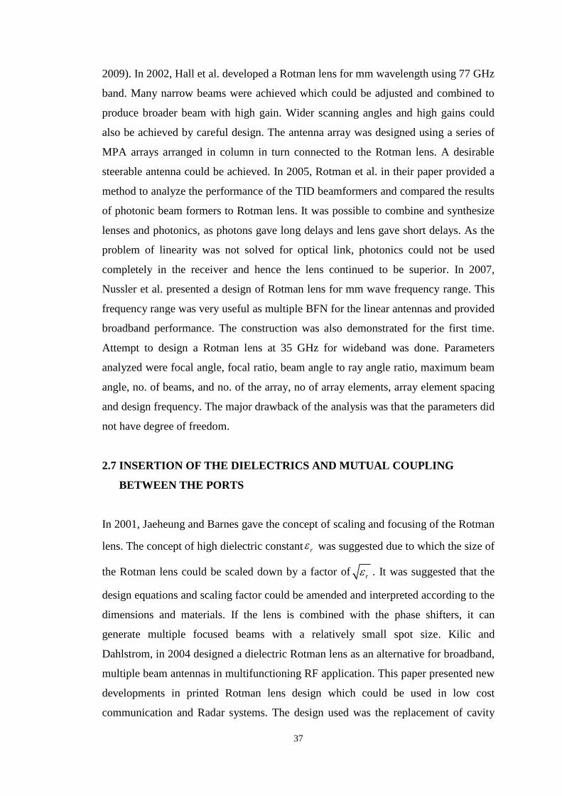
2009). In 2002, Hall et al. developed a Rotman lens for mm wavelength using 77 GHz
band. Many narrow beams were achieved which could be adjusted and combined to
produce broader beam with high gain. Wider scanning angles and high gains could
also be achieved by careful design. The antenna array was designed using a series of
MPA arrays arranged in column in turn connected to the Rotman lens. A desirable
steerable antenna could be achieved. In 2005, Rotman et al. in their paper provided a
method to analyze the performance of the TID beamformers and compared the results
of photonic beam formers to Rotman lens. It was possible to combine and synthesize
lenses and photonics, as photons gave long delays and lens gave short delays. As the
problem of linearity was not solved for optical link, photonics could not be used
completely in the receiver and hence the lens continued to be superior. In 2007,
Nussler et al. presented a design of Rotman lens for mm wave frequency range. This
frequency range was very useful as multiple BFN for the linear antennas and provided
broadband performance. The construction was also demonstrated for the first time.
Attempt to design a Rotman lens at 35 GHz for wideband was done. Parameters
analyzed were focal angle, focal ratio, beam angle to ray angle ratio, maximum beam
angle, no. of beams, and no. of the array, no of array elements, array element spacing
and design frequency. The major drawback of the analysis was that the parameters did
not have degree of freedom.
2.7 INSERTION OF THE DIELECTRICS AND MUTUAL COUPLING
BETWEEN THE PORTS
In 2001, Jaeheung and Barnes gave the concept of scaling and focusing of the Rotman
lens. The concept of high dielectric constant r was suggested due to which the size of
the Rotman lens could be scaled down by a factor ofr . It was suggested that the
design equations and scaling factor could be amended and interpreted according to the
dimensions and materials. If the lens is combined with the phase shifters, it can
generate multiple focused beams with a relatively small spot size. Kilic and
Dahlstrom, in 2004 designed a dielectric Rotman lens as an alternative for broadband,
multiple beam antennas in multifunctioning RF application. This paper presented new
developments in printed Rotman lens design which could be used in low cost
communication and Radar systems. The design used was the replacement of cavity

38
Rotman lens with a dielectric Rotman lens to minimize the overall size of the lens. By
miniaturization of Rotman lens, stacking them at the output port made elevation
scanning possible. In this paper use of surface wave Rotman lens design was used
instead of Microstrip design, which eliminated the need of ground plane at back of the
lens and reduced the use of copper for parallel plate region. Ultimately the copper
losses were reduced. Gagnon introduced refocusing procedure for dielectric-filled
Rotman lens according to Snell’s law. Therefore, applying Snell’s law yields a ratio
of r between the sine’s of the scan angle and the subtended angle of the beam
contour. This approach provided beam and array port positions which gave improved
coupling to the outermost beam ports, especially for printed lenses used with small
arrays.
In 1981, Maybell introduced a structured method for coupling co-efficient analysis of
the 2D Rotman lens. The design view of low side lobe Rotman lens requires
consideration of mutual coupling between feed port and array port. The coupling and
internal reflection affect the amplitude and the phase distribution of the radiating array
element. The model was the basis for improved accuracy of array port coupling
coefficient calculations. In 1991, Hansen developed the design trades for Rotman
lens. The design of Lens involved both geometric trades and mutual coupling effects
between the lens ports. This paper described the geometric design trades. Calculation
of lens gain was presented with lens connected to an array of isotropic elements. In
1999, Peterson and Rausch developed and designed a scattering matrix integral
equation for the design of waveguide Rotman lens. The design equations don’t
specify the shape of a sidewall that joins the lens focal port to lens ray port, which
affect side lobe level and insertion loss.
2.8 OTHER DESIGN TRADES USED FOR THE DEVELOPMENT OF THE
ROTMAN LENS ANTENNA
Besides the extensive survey related to the work done in improvisation of side lobes,
reduction of the phase error, effect of insertion of the dielectric material and mutual
coupling between the ports, few other design trades in the development of the
Rotman lens antenna have been surveyed. In 1989, Chan worked on the concept of
phased array antennas fed by Rotman lens to improve the radar system performance
in a number of areas. In this paper the analysis of stripline and microstrip lens was

39
done. In 1992, Hansen designed the pattern control synthesis in which the antenna
array distribution and its associated patterns were designed for physical principals
based on the placement of zeros of the array polynomial. The control of side lobe
topology in pencil beam patterns, and the synthesis of various shapes of beamed
patterns were discussed. The main emphasis of linear and planar broadside apertures
and arrays using Dolph, Chebyshev and Tailor distributions. The design allowed
adjustable side lobes. In 2005, Weiss and Dahlstrom did the analysis of Rotman lens
at the Army Research Lab. They discussed the development of Rotman lens beam
formers over last 10 years. One successful version was cavity Rotman lens that served
as Azimuthal beam former for ESA, which supported multiple operations in Ka band.
Many patents related to Electronic warfare were developed at Raytheon.
At Raytheon, work was done on reducing the size of the lens by loading the parallel
plate region by dielectric material and the result can be seen in Figure 2.2. In 1970,
Two-dimensional Rotman lens stack was demonstrated. In 1973, Archer et al.,
proposed the idea of implementing Rotman lens using printed technologies to have a
low profile lens. The studies on microstrip/stripline Rotman lens increased.
Figure 2.2 The Gent Bootlace Configuration (Gent, 1957)
a. Lens deign by Rotman and Turner
The Rotman lens design approach by Rotman and Turner started way back in 1963.
This work starts with the review of the conventional Rotman lens antenna design. The
conventional design consisted of a parallel conducting plate, beam port, array port and
array of radiating elements. The transmission lines connect the inner lens contour and
40
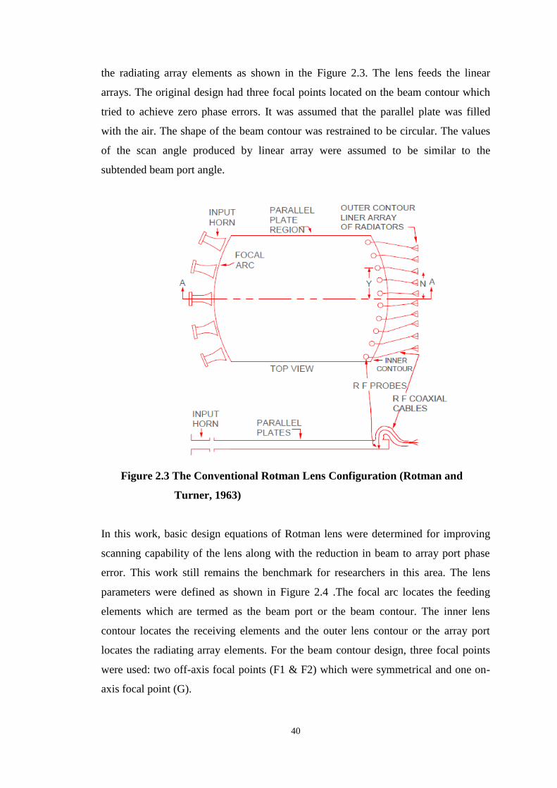
the radiating array elements as shown in the Figure 2.3. The lens feeds the linear
arrays. The original design had three focal points located on the beam contour which
tried to achieve zero phase errors. It was assumed that the parallel plate was filled
with the air. The shape of the beam contour was restrained to be circular. The values
of the scan angle produced by linear array were assumed to be similar to the
subtended beam port angle.
Figure 2.3 The Conventional Rotman Lens Configuration (Rotman and
Turner, 1963)
In this work, basic design equations of Rotman lens were determined for improving
scanning capability of the lens along with the reduction in beam to array port phase
error. This work still remains the benchmark for researchers in this area. The lens
parameters were defined as shown in Figure 2.4 .The focal arc locates the feeding
elements which are termed as the beam port or the beam contour. The inner lens
contour locates the receiving elements and the outer lens contour or the array port
locates the radiating array elements. For the beam contour design, three focal points
were used: two off-axis focal points (F1 & F2) which were symmetrical and one on-
axis focal point (G).

41
Figure 2.4 Rotman lens geometry (Rotman and Turner, 1963)
The shape of the focal arc was chosen as a circle. In order to derive design equations
for the lens contour, optical path-length equality and the lens geometry was used.
Still, there is scope to further reduce the path length error.
b. Symmetrical Lens approach by Shelton
Figure 2.5 Symmetrical Lens by Shelton (Shelton, 1978)
Shelton, in 1978 developed a symmetrical lens configuration as a modification to the
Rotman lens. The beam and the inner lens contours are identical and symmetrical with
respect to a symmetry plane as shown in Figure 2.5. The design equations of this type
of lens were more complicated than that of Rotman’s.

42
c. Lens design approach by Katagi
In 1984, Katagi improvised the design equations given by Rotman and Turner by
adding a new variable which reduced the phase error on the aperture of the linear
array antenna as shown in Figure 2.6 below. This design parameter helped in reducing
the size of the lens. Katagi defined a subtended angle (α) corresponding to one of the
off-axis focal points as defined in Rotman’s model. However, the scan angle (β)
corresponding to the excitation from F1 is assumed to be different from the subtended
angle (α) though scan angles were assumed to be equal to the corresponding
Figure 2.6 Katagi’s design of the lens (Katagi et al., 1984)
subtended angles in Rotman’s design model. The new design variable provided a new
degree of freedom compared to the conventional design. Katagi also suggested that it
was not necessary to keep the shape of the beam contour as circular.
d. Design trades by Hansen
In 1991, Hansen used few basic design parameters like, focal angle, focal ratio, beam
angle to ray angle ratio, maximum beam angle, focal length and array element
spacing. One more parameter of ellipticity was introduced which assumed the beam

43
contour to be elliptical instead of circular. The parameter beam angle (subtended
angle) to ray angle (scan angle) ratio and ellipticity were additions to the parameters
of the conventional design. Hansen explained the effects of these design parameters
on the shape, phase and amplitude errors of a Rotman lens.
e. Other design approaches
The quadrufocal bootlace lens was first proposed to design three dimensional lens
BFN’s by Rao in 1982 and modification in the design was presented in 1983. In 2009,
non-focal lens design for reduction of phase error and improvement of scanning lens
was presented by Zaghloul and Dong. It evolved that the phase error in case of a
conventional Rotman lens could be reduced by adopting a non- focal design strategy
as proposed by Dong, Zaghloul and Rotman. In 2009, Uyguroglu et al. introduced a
new concept of feed curves such that the phase error was reduced. The method was
based on having three zero error positions on the radiating array for each feed curve
point. In the same year, Zalevsky et al., proposed improved design of photonic
Rotman lens which was capable of realizing a linear phase profile with a variable
slope, which could be obtained at the output of the lens for any possible position at
the input to the lens.
After 2009 various researchers are still trying to improve the design of the lens so as
to achieve a wide angle scanning with low loss and minimum phase error. Use of
various existing optimization techniques, namely GA, PSO, simulated annealing, etc.
can come handy in improving the performance of the lens (Weile and Michielssen,
1997; Goldberg, 1989; Liang et. al., 2005; Venkatraman and Yen, 2005).
In 2012, Christie et al. proposed a new type of broadband retro directive array, which
had been constructed using a microstrip Rotman lens. Automatic tracking of targets
was obtained by exploiting the conjugate phase response of the BFN, which was
exhibited when the input ports were terminated with either open or short circuits.
Singhal et al. designed Rotman lens for wide area scanning and compared the lens
with the various other existing designs. He also proposed the fact that the height of the
array and feed contours must be same for maximum power transfer and better lens

44
performance. Effect on shape of beam and array contour by variation in scanning
angle, focal ratio and element spacing were prime issues of his work.
In 2012, Rajabalian and Zakeri presented the concept of non-focal microwave lens
design with optimization of phase errors and amplitude performance. In the same year
Hung-I Lin and Wen proposed the array antenna which consisted of a Rotman lens
and four element antennas. In 2013, Zongxin et al. developed a compact printable
multibeam antenna array. The antenna system was composed of a printed Rotman
lens and an antipodal dual elliptically tapered slot antenna array; both the components
were studied, respectively, at first, and then integrated on a single printed circuit
board to make up the integrated unit of the multibeam antenna array. In the same year
Yunhua Zhang et al. came up with the concept of side lobe modulation scrambling
transmitter using Fourier Rotman lens, wherein they developed a means for
scrambling the digital modulation content in the side lobes of a radio transmission
from a steerable antenna array. In 2013; Fonseca developed an improved design
method for two-dimensional Rotman lens with reduced phase-aberrations. This paper
introduced an improved design method supported by analytical formulas defining the
focal curve of a Rotman lens with reduced worst-case phase-aberrations. In the same
year, Joo-Rae Park and Dong Chung Park proposed a refocusing method for
minimizing the phase errors of Rotman lenses. The method was based on finding the
optimal α, F, and γ minimizing the phase errors by moving off-axis focal points along
a beam curve. It ensured the additional phase error reduction without significant
changes of beam and array curve shapes. In 2014; Jaeheung Kim et al. presented their
work on asymmetric ground Rotman lens. A new design of a Rotman lens was
proposed to accommodate a whole beamforming system by providing separate ground
layers for antennas and circuits. The lens had three dielectric layers and four metallic
layers. In the same year he presented a new approach to analyze a Rotman lens for
imaging applications. The Optical Transfer Function (OTF) was used to analyze the
imaging capability of a Rotman lens. As a result, it was found that the cutoff
frequency corresponds to the array size in λ. In 2014; Rusch Christian et al. designed
the 2D-beam-forming device consisting of a Rotman-lens and a holographic antenna.
A lot of design performances get affected by varying different lens parameters. In
view of all the above mentioned facts by various researchers it is quite clear that still

45
there was a scope of improvement in the performance of the lens by applying
optimization techniques in electromagnetics.
2.9 GAP IN THE STUDY
The growing complexity of the overall communication system has motivated the
need for the antenna which is capable of forming multiple simultaneous beams with
reduced path length error. The performance of the system could be limited due to
inefficient lens design. It is based on true time delay (TTD) which means that it is
not dependent on the frequency. This ultimately removes the need of phase shifters,
which are used to steer the beam over wide range angles. After thorough literature
survey it emerged that still lot of work can be done to improve the design of the lens
so as to achieve a wide angle scanning and minimum phase error. The determination
of the main optical parameters of the lens geometry i.e. the positions of the beam
port, the receiving ports and the length of the transmission line has been very
complex. These parameters are the results of many other interdependent design
parameters that affect the phase error performance. These are some of the issues
which can be investigated and simplified further. It has been perceived that still
there is a lot of scope to analyze the effects of various design parameters i.e. the
focal ratio and the element spacing on the performance parameters of the lens like
path length error, array factor, return loss, and insertion loss. To further ameliorate
the scanning angle and the path length error or the phase error of the lens antenna,
few new design parameters such as beam to array phase error and beam to array
coupling amplitude may be introduced and investigated along with the existing
parameters such as return loss, insertion loss and array factor to enhance the overall
performance of the lens. The effect of these new design variables have been rarely
reported in the literature earlier.
From the literature survey, it transpired that, by introducing a new design variable
and by using PSO technique, maximum scanning of 450
could be achieved with
reduced phase error. It appeared that by applying GA and PSO techniques, the
scanning angle can be further improved by reducing phase error and without
distorting the shape of the lens. It emerged from the study that the change of shape

46
and substrate of the lens could also affect various performance parameters of the lens
like array factor, beam to array port phase error, beam to array coupling amplitude
and insertion loss. The work related to the same has been rarely reported in the
survey.
2.10 CONCLUSIONS
Rotman lens has proved to be a popular multiple beam-forming technologies, due to
its simplicity and good performance. The above chapter gives the details of the
various developmental stages in the microwave lens and various BFN. From the
literature survey, it has been concluded that a lot of work has been done in the
designing of the lens and enhancing its performance by working on various
parameters. Different design techniques have been used to attain the desired
performance of the lens.
It has been perceived that the individual contribution of main design parameters of the
lens like path length error or the phase error, return loss, insertion loss, side lobes
levels and focal length on the performance of the lens has been reported earlier, but
the combined effect of all the parameters taken together on the performance of the
lens is rarely available in the literature. Moreover, it has also been observed that the
effect of many important lens parameters like beam to array coupling amplitude and
beam to array phase error have been hardly considered for the design of the Rotman
lens. The effect of design parameters such as element spacing and focal ratio on the
performance of the lens has been rarely considered. Earlier, PSO technique had been
used as the optimization tool for achieving maximum scanning angle and reducing
phase error. There are other optimization mechanisms available such as GA which
can be utilized to further improve the parameters of the lens for better performance.
The effect of change of shape of the lens and the substrate in the cavity may also
affect the performance of the lens. This needs to be further investigated.
The next chapter describes the conventional Rotman lens. It covers the development
and investigation of the basic design equations of the lens and determination of phase
error.