chapter-6svbitce2010.weebly.com/uploads/8/4/4/5/8445046/ppt_chapter_6...similarly by reading from...
TRANSCRIPT

SUBJECT:- Operating System
Chapter-6
SUBJECT:- Operating SystemTOPICS:- I/O Management
Created by : - Sanjay Patel

Disk Scheduling Algorithm1) First-In-First-Out (FIFO)2) Shortest Service Time First (SSTF)3) SCAN4) Circular-SCAN (C-SCAN)
Created by : - Sanjay Patel2
4) Circular-SCAN (C-SCAN)5) LOOK
Disk Scheduling Algorithm
ØIn this algorithm, the vertical axis corresponds to thetracks on the disk.
ØThe horizontal access corresponds to time or,equivalently, the number tracks traversed.
Created by : - Sanjay Patel3
equivalently, the number tracks traversed.

FIFOFIFOFIFOFIFOvProcess requests as they comevFair (no starvation)vGood for a few processes with clustered requests vDeteriorates to random if there are many processes.
Created by : - Sanjay Patel 4
ØWe also assume that a disk with 200 tracks, in orderreceived by the disk scheduler, are 55, 58, 39, 18, 90, 160,150, 38, 184
ØWe assume that the disk head is initially located tracks100.

Created by : - Sanjay Patel 5

Next track accessed Numbers of trackstraversed
55 45
58 3
39 19
18 21
FIFO (Starting at track 100)
Created by : - Sanjay Patel6
18 21
90 72
160 70
150 10
38 112
184 146
Average Seek Length 55.3

SSTFSSTFSSTFSSTFvThe SSTF policy is to select the disk I/O request thatrequires the least movement of the disk arm from itscurrent position.
vThus, we always choose to incur the minimum seek time.
Created by : - Sanjay Patel 7
vOf course, always choosing the minimum seek time doesnot guarantee that the average seek time over a number ofarm movements will be minimum.vHowever, this should provide better performance thanFIFO. Because arm can move in two direction, a random tie-breaking algorithm may be used to resolve cases of equaldistances,

Created by : - Sanjay Patel 8

Next track accessed Numbers of trackstraversed
90 10
58 32
55 3
39 16
SSTF (Starting at track 100)
Created by : - Sanjay Patel 9
39 16
38 1
18 20
150 132
160 10
184 24
Average Seek Length 27.5
SCAN (Elevator Algorithm)SCAN (Elevator Algorithm)SCAN (Elevator Algorithm)SCAN (Elevator Algorithm)
üWith exception FIFO, all of the polices described so farcan leave some request unfulfilled until the entire queue isemptied.
üThat is, there may always be new requests arriving that
Created by : - Sanjay Patel 10
üThat is, there may always be new requests arriving thatwill be chosen before an existing request.
üA simple alternative that prevents this sort of starvation isthe SCAN algorithm, also known as elevator algorithmbecause it operates much the way an elevator does.

Created by : - Sanjay Patel 11

Next track accessed Numbers of trackstraversed
150 50
160 10
184 24
90 94
SCAN (Starting at track 100, In the direction of increasing track number)
Created by : - Sanjay Patel12
90 94
58 32
55 3
39 16
38 1
18 20
Average Seek Length 27.8

Circular SCAN (CCircular SCAN (CCircular SCAN (CCircular SCAN (C----SCAN)SCAN)SCAN)SCAN)
üThe C-SCAN policy restricts scanning to one directiononly. Thus, when the last track has been visited in onedirection, the arm is returned to the opposite end of thedisk and the scan begins again.
üThis reduces the maximum delay experienced by new
Created by : - Sanjay Patel 13
üThis reduces the maximum delay experienced by newrequests.
üLike elevator, but reads sectors in only one direction;When reaching last track, go back to first track non-stop
üBetter locality on sequential readsüBetter use of read ahead cache on controllerüReduces max delay to read a particular sector

Created by : - Sanjay Patel14

Next track accessed Numbers of trackstraversed
150 50
160 10
184 24
18 166
C-SCAN (Starting at track 100, In the direction of increasing track number)
Created by : - Sanjay Patel 15
18 166
38 20
39 1
55 16
58 3
90 32
Average Seek Length 35.8

Look Scheduling Algorithm� Both SCAN and C-SCAN move the disk arm across the full width of the disk.
� In practice, neither algorithm is implemented in this way.More commonly, the arm goes only as far � More commonly, the arm goes only as far as the final request in each direction.
� Then ,it direction immediately ,without going all the way to the end of the disk.
� These version of SCAN and C-SCAN are called LOOK and C-LOOK scheduling.
Created by : - Sanjay Patel 16

Disk Scheduling AlgorithmName Description Remarks
SSTF Shortest service time first(#)
High utilization, small queues
SCAN Back and forth Better service
Created by : - Sanjay Patel17
SCAN Back and forth over disk(#)
Better service distribution
C-SCAN One way with fast return(#)
Lower service variability
FIFO First in first out(*) Fairest of them all
*: - Selection according to requestor# : - Selection according to request item

ExampleExample
� The disk request queue contains a set of reference for blocks on tracks 98, 183, 37, 122, 14, 124, 65, 67. And head pointer at 53, draw and count head pointer at 53, draw and count average seek length for FIFO, STF, SCAN, C-SCAN
Created by : - Sanjay Patel 18

ExampleExample
� The disk request queue contains a set of reference for blocks on tracks 76, 124, 17, 269, 201, 29, 137, 12. And head pointer at 76, draw and count head pointer at 76, draw and count average seek length for FIFO, STF, SCAN, C-SCAN
Created by : - Sanjay Patel 19

I/O SYSTEMI/O SYSTEM--OVERVIEWOVERVIEW
There are mainly two jobs for computer those are
üI/O ü processingü processingqFor example if we are making sum of twonumbers process then first we have toread two number and then afterprocessing result should be displayed onthe screen which involves the I/O.
Created by : - Sanjay Patel 20

Principles of Input Output Principles of Input Output HardwareHardware
� I/O devices can be roughly divided into two categories:
üBlock Devices:- A Block Device is one that stores information in fixed-size blocks. Commonly the block size in block device is Commonly the block size in block device is 512 bytes to 32,768 bytes. Disk is most common block device.
üCharacter Devices :-A Character Device read or writes a stream of character. Network interface, mouse, keyboard, etc. are character device.
Created by : - Sanjay Patel 21

Device ControllerDevice ControllervInput output units typically consists of a
mechanical component and an electronic component. The electronic component is called the device controller or adapter. The mechanical component is the device itself.mechanical component is the device itself.
vThe interface between the controllers and the device is often a very low level interface. The controller job is to convert the serial bit stream into a block of bytes and perform any error correction necessary.
Created by : - Sanjay Patel 22

Created by : - Sanjay Patel 23

MemoryMemory--Mapped I/OMapped I/O� An input output device is managed by having software read/ write information from/to controller’s registers. The computer designers must decide what instructions will be included in the machine repertoire to manipulate each controller’s registers.
� Traditionally, the machine instruction set includes special input output instruction to accomplish this task.input output instruction to accomplish this task.
� Each I/O controller has a few registers that are used for communicating with the CPU. By writing into these registers, the operating system can send command or data to device.
� Similarly by reading from these registers, the operating system can accept the request, status or data from the device.
Created by : - Sanjay Patel 24

How CPU can communicate with How CPU can communicate with these control registers?these control registers?
� Each control register has assigned an I/O port number. During reading or writing from these controls registers CPU uses the port number.
� But in this scheme the address given by the � But in this scheme the address given by the CPU and the address of I/O control register is different so we have to map the memory address given by CPU with control register address.
� To solve this mapping problem we have to use memory-mapped I/O technique
Created by : - Sanjay Patel 25

MemoryMemory--Mapped I/OMapped I/O� In this technique control register has assigned unique memory address inside the computer memory. For these purpose some upper memory region is reserved.
� In Pentium system approximately 640 KB to � In Pentium system approximately 640 KB to 1 MB memory reserved for this purpose.
� In other words, Each control register is assigned a unique memory address to which no memory is assigned. This system is called memory mapped input output
Created by : - Sanjay Patel 26

Advantages Of memory Advantages Of memory mapped I/Omapped I/O
vThere is no special protection mechanism required for the memory because of each control register has assigned fixed memory location.
v Every instruction that can referencev Every instruction that can referencememory can also reference controlregisters.
v Device control registers are just variablesin memory and can be addressed innormal way
Created by : - Sanjay Patel 27

Disadvantages Of memory Disadvantages Of memory mapped I/Omapped I/O
� If there is only one address space, then all memory modules and all input output devices must examine all memory references.
� Caching a device control register would be disastrous. So solution to this problem is that we have to disable the caching.
Created by : - Sanjay Patel 28

Direct Memory Access (DMA)Direct Memory Access (DMA)� A special control unit may be provided to
allow transfer of a block of data directly between an external device and the main memory, without continuous intervention by the processor. This approach is called Direct Memory Access (DMA).Memory Access (DMA).
� DMA can be used with either interrupt software Figure shows the typical DMA block diagram. DMA is particularly useful on devices like disks, where many bytes of information can be transferred in single I/O operations
Created by : - Sanjay Patel 29

Block diagram of DMABlock diagram of DMA
Created by : - Sanjay Patel 30

DMADMA� DMA mechanism can be configured in a variety of ways
1) Single bus, detached DMA2) I/O BusWhen used in conjunction with an interrupt, � When used in conjunction with an interrupt, the CPU is notified only after the entire block of data has been transferred. For each byte or word transferred, it must provide the memory address and all the bus signals that control the data transfer
Created by : - Sanjay Patel 31

Single bus, detached DMASingle bus, detached DMA
� All the modules use same system bus.� This configuration is inefficient but
inexpensive.� It uses programmed I/O to exchange data � It uses programmed I/O to exchange data
between memory and an I/O module through the DMA module.
Created by : - Sanjay Patel 32

I/O BusI/O Bus� I/O Bus provide easily expandable configuration.� It reduces number of I/O interface in the DMA module.
� Exchange of data between the DMA and I/O module takes place off the system busmodule takes place off the system bus
Created by : - Sanjay Patel 33

DMA Data Transfer operation…….DMA Data Transfer operation…….Program => PDevice => D1) Program makes a DMA setup request.2) Program deposits the address value A and
the data count (d).3) Program also indicates the virtual memory 3) Program also indicates the virtual memory
address of the data on disk.4) DMA controller records the receipt of
relevant information and acknowledges the DMA complete.
5) Device communicates the data to the controller buffer.
Created by : - Sanjay Patel 34

DMA Data Transfer operationDMA Data Transfer operation
6) The controller grabs the address bus and data bus to store the data, one word at a time. 7) Data count is decremented.7) Data count is decremented.8). The above cycle is repeated till the desired data transfer is accomplished
Created by : - Sanjay Patel 35

TermsTerms� Interrupt: A suspension of process, such as theexecution of a computer program, caused by anevent external to that process and performed insuch a way that the process can be resumed.
� Device Driver : - an operating system module(usually in the kernel) that deals with directly with(usually in the kernel) that deals with directly witha device or I/O module.
� Interrupt Handler : - a routine, generally part ofOS. When an interrupt occurs, control istransferred to the corresponding interrupthandler, which take some action in response tothe condition that caused the interrupt.
Created by : - Sanjay Patel 36

Principles of I/O softwarePrinciples of I/O software� A key concept in the design of I/O
software is known as device independence. What it means is that is should be possible to write programs that can access any I/O device without having can access any I/O device without having to specify the device in advance.
üuniform naming:- The name of a file or a device should simply be a string or an integer not depend on the device in any way.
Created by : - Sanjay Patel 37

� Error handling:- Errors should be handled as close to the hardware as possible.
� synchronous (blocking) or Asynchronous (interrupt-driven) :- Most physical I/O is asynchronous- the CPU starts the transfer and goes off to do something else until the interrupt arrives.
� Buffering:- Often data come off a device can � Buffering:- Often data come off a device can not be stored directly in its final destination. Buffering involves considerable copying.
ü For example, when a packet comes in off the network, the operating system does not know where to put it until it has stored the packet and examined it.
Created by : - Sanjay Patel 38

Interrupt Driven I/O….Interrupt Driven I/O….� Whenever a data transfer to or from themanaged hardware might be delayed for anyreason, the driver writer should implementbuffering. Data buffers help to detach datatransmission and reception from the write andread system calls, and overall system performancebenefits.read system calls, and overall system performancebenefits.
� A good buffering mechanism leads to interrupt-driven I/O, in which an input buffer is filled atinterrupt time and is emptied by processes thatread the device; an output buffer is filled byprocesses that write to the device and is emptiedat interrupt time.
Created by : - Sanjay Patel 39

Interrupt Driven I/OInterrupt Driven I/O� For interrupt-driven data transfer to happensuccessfully, the hardware should be able togenerate interrupts with the following semantics:◦ For input, the device interrupts the processor whennew data has arrived and is ready to be retrieved bythe system processor. The actual actions to performdepend on whether the device uses I/O ports,the system processor. The actual actions to performdepend on whether the device uses I/O ports,memory mapping, or DMA.◦ For output, the device delivers an interrupt eitherwhen it is ready to accept new data or toacknowledge a successful data transfer. Memory-mapped and DMA-capable devices usually generateinterrupts to tell the system they are done with thebuffer.
Created by : - Sanjay Patel 40

Interrupt HandlersInterrupt HandlersØ The address of the interrupt handlers is stored as anindirect address in memory when the machine is started.
Ø The interrupt handler is a part of the OS that will beexecuted when any device completes its operations. Sothe application software need not continuously poll thedevice to detect when it has completed.
Ø When then interrupt handler begins execution, the CPUØ When then interrupt handler begins execution, the CPUregister will obtain values being used by the interruptedprocess.
Ø The interrupted handler must immediately perform acontext switch to save all the general and statusregisters of the interrupted process and to install itsown values for every CPU registers so that it canhandle the completion of the input output operation.
Created by : - Sanjay Patel 41

Steps are performed in software after the Steps are performed in software after the hardware interrupt has completed.hardware interrupt has completed.
1) Save any registers that have not already been saved by the interrupt handler.
2) Set up a context for the interrupt service procedure.
3) Set up a stack for the interrupt service procedure.4) Acknowledge the interrupt controller. If there is
no centralized interrupt controller.no centralized interrupt controller.5) Copy the registers from where they were saved to
the process table.6) Run the interrupt service procedure.7) Choose which process to run next.8) Set the MMU context for the process to run next.9) Load the new process registers.10) Start running the new process.
Created by : - Sanjay Patel 42

Device DriversDevice Drivers� Each input output device attached to a computerneeds some device specific code for controlling it.This code, called the device driver, is generallywritten by the device’s manufacture and deliveredalong with the device.Each device driver normally handles one device� Each device driver normally handles one devicetype, or at most, one class of closely relateddevices. Device drivers are normally positionedbelow the rest of the operating system
� Drivers are not allowed to make system calls, butthey often need to interact with the rest of thekernel.
Created by : - Sanjay Patel 43

Created by : - Sanjay Patel 44

BufferingBuffering� Buffering is a technique by which the device manager can keep slower I/O devices busy during times when a process is not requiring I/O operations.
� Types of I/O buffering schemes1) Single buffering2) Double buffering3) Circular buffering4) No buffering
Created by : - Sanjay Patel 45

Single BufferSingle Buffer� Operating system assigns a buffer in the system portion of main memory.
Block oriented deviceü Input transfers are made to the system buffer.ü After transferring, the process moves the block ü After transferring, the process moves the block into user space and request for another block.
ü User process can be processing one block of data while the next block is being read in.
ü OS is able to swap the process out.ü OS must keep track of the assignment of system buffers to user processes.
Created by : - Sanjay Patel 46

Double BufferDouble Buffer� There are two buffers in the systemü One buffer is for the driver or controller to store data while waiting for it to be retrieved by higher level of the hierarchy.
ü Other buffer is to store data from the lower level module.
ü Double buffer is also called buffer ü Double buffer is also called buffer swapping.
ü Double buffering improvement comes at the cost of increased complexity.
ü Double buffering may be inadequate if the process performs rapid burst of I/O.
Created by : - Sanjay Patel 47

Circular BufferCircular Buffer
ØWhen more than two buffers are used,the collection of buffers is itself referredto as a circular buffer.
ØIn this, the procedure can not pass theØIn this, the procedure can not pass theconsumer because it would overwritebuffers before they had been consumed
Created by : - Sanjay Patel 48

RAIDRAID� Redundant array of independent disks may be used toincrease disk reliability.
� RAID is a storage technology that combines multipledisk drive components into a logical unit. Data isdistributed across the drives in one of several wayscalled "RAID levels", depending on what level ofredundancy and performanceIn a RAID system, a single large file is stored in� In a RAID system, a single large file is stored inseveral separated disk units by breaking the file up tointo a number of smaller pieces and storing thesepiece on different disks.
� When a file is accessed for a read, all disks delivertheir data in parallel.
� RAID may be implemented in hardware or in theoperating system.
Created by : - Sanjay Patel 49

RAID level 0RAID level 0
Created by : - Sanjay Patel 50
It creates one large virtual disk from a number of smaller disks.Storage is grouped into logical unit called strips.The strips are mapped round-robin to consecutive array members.The virtual storage is a sequence of strips interleaved among the disksin the array.RAID level 0 architecture achieves the parallism but it does not includeredundancy to improve reliability.

RAID level 0RAID level 0
� Benefit: - create a large disks.� Limitation: - files tend to get scattered over a number of disks, even after a disk over a number of disks, even after a disk failure, some file data may be retrievable.
Created by : - Sanjay Patel 51

RAID level 1RAID level 1(mirrored)(mirrored)
� Redundancy is achieved by just duplicating all the data.
� The data stripping is used, same as RAID level 0.� RAID level 1 stores duplicate copies of each strip, with each copy on a different disks.strip, with each copy on a different disks.
Created by : - Sanjay Patel 52

RAID level 2RAID level 2(Error correcting code)(Error correcting code)
� Single copies of each strip are maintained.� Error correcting code such as hamming code is calculated for the corresponding bits on each data disk.
� The bits of code are stored in the corresponding bit positions on multiple parity disks.positions on multiple parity disks.
� The strips are very small , so when a block is read, all disks are accessed in parallel.
Created by : - Sanjay Patel 53

RAID level 3RAID level 3(Bit parity)(Bit parity)
� In RAID level 3, single parity bit is used instead of an error correcting code.
� A parity bit is a bit that is added to ensure that the number of bits with the value one in a set of bits is evenor odd. Parity bits are used as the simplest form of error detecting code. It requires just one extra disk.error detecting code. It requires just one extra disk.
� The data stripping is used, similar to the other RAID levels.
� If any disk in the array fails, its data can be determined from the data on the remaining disks.
Created by : - Sanjay Patel 54

RAID levelRAID level--44(Block Level Parity)(Block Level Parity)
� RAID level 4 is similar to RAID level 3, except strips are larger.
� Operation to read a block involves only a single disk.� Parity bits are stored in corresponding strip on the parity disk.
� A bit by bit parity strip is calculated across � A bit by bit parity strip is calculated across corresponding data blocks on each data disk.
Created by : - Sanjay Patel 55

RAID level 5RAID level 5(Block level Distributed Parity)(Block level Distributed Parity)� It eliminates the potential bottleneck found in RAID-4.� RAID-4 distributes the parity strips across all disks.
Created by : - Sanjay Patel 56
Disk FormattingDisk Formatting� Computers must be able to access needed information on command; however, even the smallest hard disk can store millions and millions of bits. How does the computer know where to look for the information it needs? To solve this problem, The most basic form of disk organization is called � The most basic form of disk organization is called formatting. Formatting prepares the hard disk so that files can be written to the platters and then quickly retrieved when needed. Hard disks must be formatted in two ways:
� Physical disk formatting� Logical disk formatting
Created by : - Sanjay Patel 57
Created by : - Sanjay Patel 58

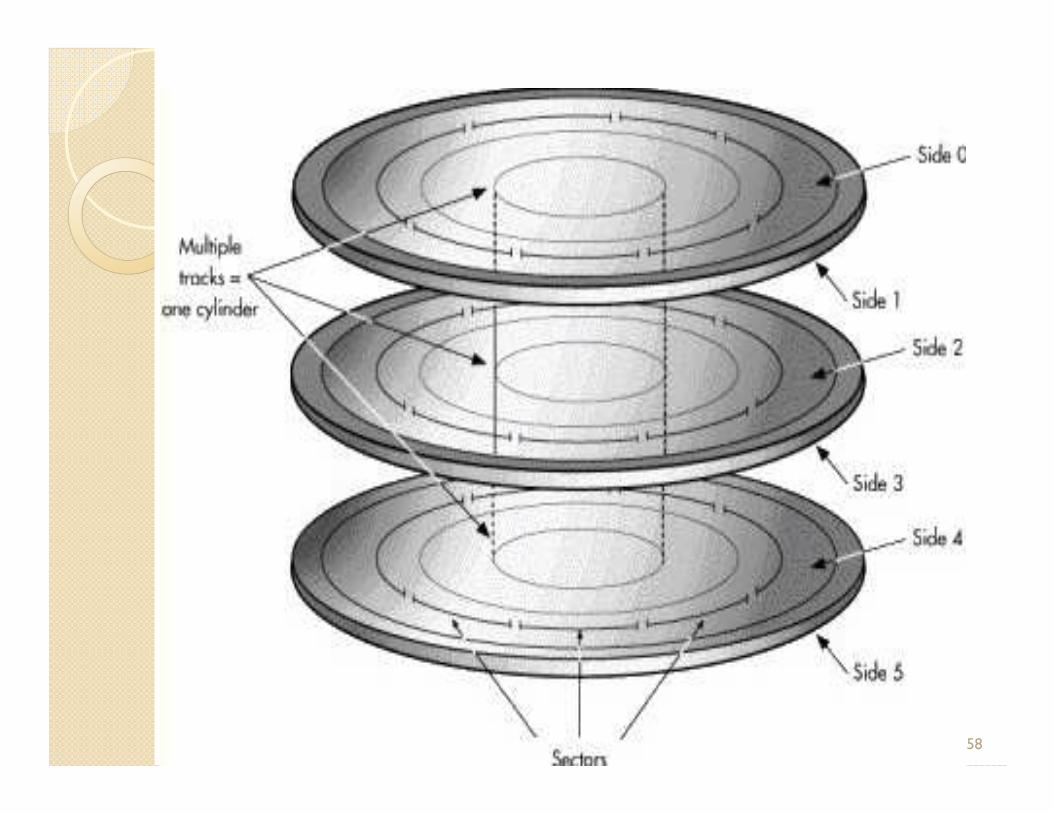
Physical FormattingPhysical FormattingØA hard disk must be physically formatted before it can be logically formatted. A hard disk's physical formatting (also called low-level formatting) is usually performed by the manufacturer.
ØDisk must be formatted before storing a data.Ø Physical formatting (as per picture) divides the Ø Physical formatting (as per picture) divides the hard disk's platters into their basic physical elements: tracks, sectors, and cylinders. These elements define the way in which data is physically recorded on and read from the disk.
ØDisk must be divided into sectors that the disk controller can read/write
Created by : - Sanjay Patel 59

Logical FormattingLogical Formatting� After a hard disk has been physically formatted, it must also be logically formatted.
� Logical formatting places a file system on the disk, allowing an operating system the disk, allowing an operating system (such as DOS, Windows, or Linux) to use the available disk space to store and retrieve files.
� After disk is partitioned, logical formatting is used.
Created by : - Sanjay Patel 60

SpoolSpool� A Spool is a buffer that holds output for a device, such as a printer, that cannot accept interleaved data streams.
� Although a printer can serve only one job at a time, several applications may wish to print their output concurrently, without having their output mixed together.
� The operating system solves this problem by � The operating system solves this problem by intercepting all output to the printer.
� Each application’s output is spooled to a separate disk file. When an application finishes printing, the spooling system queues the corresponding spool file to the printer one a time.
� In some operating system, spooling is managed by a system daemon process, in other operating systems, spooling is managed by in-kernel thread.
Created by : - Sanjay Patel 61

Disk SchedulingDisk Scheduling
�What is disk scheduling?üServicing the disk I/O requests�Why disk Scheduling?ü Use hardware efficientlyü Use hardware efficientlyIncludesØFast access time (seek time+ rotational latency)
ØLarge disk bandwidth
Created by : - Sanjay Patel 62

Created by : - Sanjay Patel 63

ExampleExample
� Ex: a disk queue with requests for I/O toblocks on cylinders
�23, 89, 132, 42, 187With disk head initially at 100�With disk head initially at 100
Created by : - Sanjay Patel 64

FIFO(23, 89, 132, 42, 187)
Created by : - Sanjay Patel 65Total Distance Traversed 77+66+43+90+145=421

SSTF(23, 89, 132, 42, 187)SSTF(23, 89, 132, 42, 187)
Created by : - Sanjay Patel 66Total Distance Traversed 11+43+55+145+19=273

Scan (Head Move to decreasing Position or towards 0) Scan (Head Move to decreasing Position or towards 0) 23, 89, 132, 42, 18723, 89, 132, 42, 187
Created by : - Sanjay Patel 67
Total Distance Traversed 11+47+19+23+132+55=287

CC--Scan Head Move to decreasing PositionScan Head Move to decreasing Position
Created by : - Sanjay Patel 68
Total Distance Traversed 11+47+19+23+199+12+55=366
Head movement can be reduced if the request for cylinder 187 is serviced directly after request at 23 without going to the disk 0

LOOK(23, 89, 132, 42, 187)LOOK(23, 89, 132, 42, 187)
Created by : - Sanjay Patel 69
Total Distance Traversed 11+47+19+109+55=241
Compared to Scan, LOOK saves going from 23 to 0 and then back.Most efficient for this sequence o SCAN, of requests

Thank You !
Created by :Created by :Created by :Created by :----
S A N J A Y P A T E LS A N J A Y P A T E LS A N J A Y P A T E LS A N J A Y P A T E LAssistant Professor (I.T.)
Shankersinh Vaghela Bapu
Institute of Technology, Gandhinagar