chapter 8: ventilation
TRANSCRIPT

WSEC Builder’s Field Guide, 7th Edition, 2006 • Washington State University Extension Energy Program 8-�
Definitionsoftermsusedinthischapter:
ACHstands for "air changes per hour." It is a measure of the ventilation rate of a room or whole structure. If half the volume of air in a room is exchanged for fresh air in one hour, then the room is being ventilated at the rate of 0.5 ACH.
CFM(orcfm) stands for "cubic feet per minute" and is used to measure the volume of ventilation air required or the capacity of a fan to move air.
Fancapacityratings are given in terms of the volume of air (in cfm) that the fan can move against a given static pressure (in inches of water gauge). For prescriptive com-pliance, the VIAQ Code requires that all fan capacities be rated at .25 inches of water gauge.
Fan Capacity Rating Example
Static Pressure; Inches of Water 0.0 0.� 0.�25 0.250 0.375
CFM 98 94 93 84 52
Staticpressureis a measure of the resistance of air move-ment through a duct system. Often used as a basis for the design and sizing of duct systems. The static pressure of duct system is essentially a back pressure the fan must overcome to achieve air movement through the duct.
Watergauge(or water column)is a scale used to show pres-sure differences. When you suck on a straw in a glass of water, the water rises in the straw because the pressure in the straw is reduced. The height that the water rises is a measure of the pressure difference inside and outside the straw. The height of a 1 inch diameter column of water is frequently used to describe the static pressure in a duct system. The static pressure of a residential ventilation duct system might typically be .15 inches of water.
Chapter 8: Ventilation

8-2 WSEC Builder’s Field Guide, 7th Edition, 2006 • Washington State University Extension Energy Program
Mechanical Ventilation Systems Required
The Washington State Ventilation and Indoor Air Quality Code (VIAQ) requires new residential structures be provided with both source-specific and whole-house ventilation systems. There are two methods for meeting this code. Section 302 provides requirements for residen-tial ventilation systems using performance or design qualification methods. Section 302 will most likely be used by mechanical engineers on complex projects and systems designed for continuous operation. Section 303 provides prescriptive direction for spot ventilation and four prescriptive options for intermittent operation whole house ventilation systems. This guide will only cover the Section 303 prescriptive paths.
Prescriptive Paths Include:
• Source Specific Ventilation (all prescriptive paths)• Whole House Ventilation Using Exhaust Fans• Whole House Ventilation Integrated with a Forced
Air Heating System• Whole House Ventilation Using a Supply Fan• Whole House Ventilation Using a Heat Recovery
Ventilation System
[V303.3]
[V303.4.�]
[V303.4.2][V303.4.4]

WSEC Builder’s Field Guide, 7th Edition, 2006 • Washington State University Extension Energy Program 8-3
VIAQ Table 3-1
Source Specific Ventilation Capacity Requirements
Source-Specific Ventilation
[V303.3] Source-specific or spot ventilation (see Figure 8-1) is required in specific rooms of the house, including:
• Kitchens• Bathrooms• Water closets• Laundry room• Indoor swimming pools or spas• Other rooms where excess water vapors or cooking
odors are produced
VIAQ Table 3-1 lists minimum ventilation rates for source-specific fans according to their location.
[V303.3.2] VIAQ Table 3-1 shows two exhaust rates, expressed in Cubic Feet per Minute (CFM). A lower CFM rate is required for continuously operating systems than for intermittently operated systems. Fan CFM are to be rated at 0.25 inches water gauge. This rating is included on the manufacturers fan curve. The CFM rating on the fan carton is usually the rating at the lower pressure of 0.10 and does not necessar-ily meet the requirements of the VIAQ.
SourceSpecificFanControls
[V303.3.3] Switches, dehumidistats, or timers that are readily accessi-ble to the occupant are required.
ModeofOperation Bathrooms Kitchens
Intermittently Operating 50 cfm �00 cfm
Continuous Operation 20 cfm 25 cfm

8-4 WSEC Builder’s Field Guide, 7th Edition, 2006 • Washington State University Extension Energy Program
SourceSpecificVentilationDucts
[V303.3.4]• Must be sized as per VIAQ Table 3-3.• Must terminate outside the structure.• Must be insulated to at least R-4 outside the
heated space.• Terminal elements must be screened and sized to be
greater than or equal to the net free area of the duct.
Source Specific Ventilation
Figure 8-1

WSEC Builder’s Field Guide, 7th Edition, 2006 • Washington State University Extension Energy Program 8-5
VIAQ Table 3-2
Ventilation Rates (CFM) for all Group R Occupancies Four Stories
Whole-House Ventilation Systems
[V303.4] VIAQ requires that in addition to source-specific venti-lation fans, a whole-house ventilation system must be installed. Prescriptive whole-house ventilation system provides fresh air for the occupants on a timed basis. For continuously operating systems you must comply with section 302.
All Whole house ventilation systems must be capable of providing the minimum ventilation rate specified in VIAQ Table 3-2. The maximum CFM is the maximum rate allowed without a heat recovery ventilation system. Heat recovery ventilation systems do not need to comply with the maximum values.
VIAQ Table 3-2 lists prescriptive whole-house fan sizes based on conditioned floor area and number of bedrooms. The prescriptive approach requires no calculations.
Floor Bedrooms Area,ft2 2orless 345678* Min. Max. Min. Max. Min. Max. Min. Max. Min. Max. Min. Max. Min. Max.
*For residences that exceed 8 bedrooms, increase the minimum requirement listed for 8 bedrooms by an additional 15 CFM per bedroom. The maximum CFM is equal to 1.5 times the minimum.
<500 50 75 65 98 80 120 95 143 110 165 125 188 140 210
501-1000 55 83 70 105 85 128 100 150 115 173 130 195 145 218
1001-1500 60 90 75 113 90 135 105 158 120 180 135 203 150 225
1501-2000 65 98 80 120 95 143 110 165 125 188 140 210 155 233
2001-2500 70 105 85 128 100 150 115 173 130 195 145 218 160 240
2501-3000 75 113 90 135 105 158 120 180 135 203 150 225 165 248
3001-3500 80 120 95 143 110 165 125 188 140 210 155 233 170 255
3501-4000 85 128 100 150 115 173 130 195 145 218 160 240 175 263
4001-5000 95 143 110 165 125 188 140 210 155 233 170 255 185 278
5001-6000 105 158 120 180 135 203 150 225 165 248 180 270 195 293
6001-7000 115 173 130 195 145 218 160 240 175 263 190 285 205 308
7001-8000 125 188 140 210 155 233 170 255 185 278 200 300 215 323
8001-9000 135 203 150 225 165 248 180 270 195 293 210 315 225 338
>9000 145 218 160 240 175 263 190 285 205 308 220 330 235 353

8-6 WSEC Builder’s Field Guide, 7th Edition, 2006 • Washington State University Extension Energy Program
FanControls
All whole-house ventilation systems must have a control with the capability of continuous operation, manual and automatic control. Twenty-four hour timers with a manual switch are the most common control.
At the time of the final inspection, the ventilation system is required to be set for a minimum of 8 hours per day. It is recommended that the fan control setting alternate between 10 minutes on and 20 minutes off.
Fan controls must have a label that reads:
Whole-HouseVentilation
(SeeOperatinginstructions)
OperatingInstructions
[V�0�.4] Installers shall provide operating instructions. Sample operating instructions are posted at
www.energy.wsu.edu/code/
[V302.3.2]

WSEC Builder’s Field Guide, 7th Edition, 2006 • Washington State University Extension Energy Program 8-7
Whole-House Ventilation Using Exhaust Fans
[V303.4.�] In addition to the requirements listed above, whole- house ventilation using exhaust fans must comply with requirements for fan ratings, sound control, duct sizing, insulation, and outdoor air inlets (see Figure 8-2).
FanRating
[V303.4.�.�] VIAQ Table 3-2 shows two exhaust rates, expressed in Cubic Feet per Minute (CFM). Fan CFM must be rated at 0.25 inches water gauge. This rating is included on the manufacturers fan curve. The CFM rating on the fan carton is usually the rating at the lower pressure of 0.10 and does not meet the requirements of the VIAQ.
To identify products that meet the VIAQ standards, use the Home Ventilating Institute’s Directory of Certified Products. The directory is certified monthly, and can be obtained from www.hvi.org
FanNoise
[V303.4.�.2] The whole-house fan must be quiet when operating. Fan noise is rated in “sones.” The VIAQ allows a 1.5 sone maximum when the fan motor is installed within 4 feet of the interior pick-up grille. Remote-mounted fans (more than 4 feet from the pick-up grille) are exempt from the sound rating requirement (see Figures 8-3 and 8-4).

8-8 WSEC Builder’s Field Guide, 7th Edition, 2006 • Washington State University Extension Energy Program
Whole-House Exhaust Ventilation
Figure 8-2

WSEC Builder’s Field Guide, 7th Edition, 2006 • Washington State University Extension Energy Program 8-9
Sound Attenuation for Surface Mounted Fans
Note: Remember, the noise rating applies to whole-house ventilation fans, not source-specific fans.
Figure 8-3

8-�0 WSEC Builder’s Field Guide, 7th Edition, 2006 • Washington State University Extension Energy Program
Exhaust Fans
Figure 8-4

WSEC Builder’s Field Guide, 7th Edition, 2006 • Washington State University Extension Energy Program 8-��
VIAQ Table 3-3
Prescriptive Exhaust Duct Sizing
1. For each additional elbow subtract 10 feet from length.2. Flex ducts of this diameter are not permitted with fans of this size.
Exhaust Ducts
[V303.4.�.4] Prescriptively installed ventilation systems have specific ductwork requirements to ensure adequate air flow, mini-mize condensation, and exhaust moisture and pollutants to the outside. Exhaust ducts must:
• Be sized and installed according to VIAQ Table 3-3.• Have a backdraft damper.• Be insulated to R-4, if run in an unheated space.• Terminate outside the building.
VIAQ Table 3-3 gives minimum duct sizes, length of run, and number of elbows (90° bends) based on the size of the fan. The table applies to smooth wall and flexible ducts.
FanTestedCFM MinimumFlex Maximum Minimum Maximum Maximum @0.25”W.G. Diameter LengthFeet SmoothDiameter LengthFeet Elbows1
50 4inch 25 4inch 70 3
50 5inch 90 5inch 100 3
50 6inch NoLimit 6inch NoLimit 3
80 4inch2 NA 4inch 20 3
80 5inch 15 5inch 100 3
80 6inch 90 6inch NoLimit 3
100 5inch2 NA 5inch 50 3

8-�2 WSEC Builder’s Field Guide, 7th Edition, 2006 • Washington State University Extension Energy Program
Outdoor Air Inlets
[V303.4.�.5] Each habitable space of the building must be provided with outdoor air. Outdoor air distribution is accomplished through the use of outdoor air inlets (see Figure 8-5). These openings must:
• Have controllable and secure openings.• Be sleeved when installed through a wall or window
frame.• Have a minimum of 4 square inches of net free area
or provide a minimum of 10 CFM @ 10 pascals tested by HVI.
If a door separates a fresh air inlet from an exhaust point, airflow can be ensured by either:
• Undercutting doors a minimum of 1/2-inch above the finish floor material.
• Or installing distribution ducts, grilles, or transoms.
Exception:Exhaust only ventilation systems do not require outdoor air inlets if the home has a ducted forced air heating system that communicates with all habitable rooms and the interior doors are undercut to a minimum of 1/2 inch above the surface of the finish floor covering.

WSEC Builder’s Field Guide, 7th Edition, 2006 • Washington State University Extension Energy Program 8-�3
(See Figure 3-15 for installation detail.)
Double duty spot/whole-house ventilation system.
Figure 8-5
Types of Whole-House Ventilation Using Exhaust Fans
Double-DutySpot/Whole-House:A common whole-house ventilation strategy is to combine a source-specific and whole-house ventilation fan. If possible, choose a bath-room or laundry room with a centrally located spot fan for the double-duty system. To prescriptively size the fan, use VIAQ Table 3-2. Don’t add both spot CFM rates and whole-house rates together to determine the fan size. Use the larger of the two rates (see Figure 8-2 for a typical spot/whole-house system set-up).
This type of ventilation system includes:
• A 1.5 sone (or less) rated fan.• Automatic and manual controls.
Outdoor Air Inlets

8-�4 WSEC Builder’s Field Guide, 7th Edition, 2006 • Washington State University Extension Energy Program
• Undercut doors (or other means) for air distribution.• Proper duct sizing, length, and insulation (when
outside the conditioned space).• Fresh air supplied to habitable spaces.
SeparateSpot/Whole-House: Another ventilation strategy is installing a dedicated whole-house fan in addition to the spot ventilation fans. An advantage to this system is the ability to centrally locate the whole-house fan and have it operate independently of the spot ventilators. This system may be a good choice in large houses where there are no centrally located spot fans. CFM rates, controls, air distri-bution, and duct requirements for the double-duty system also apply to this system.
CentralDuctedWhole-House:A central ducted system is typically installed in the attic and ducted to individual areas of the house, bathrooms, kitchen, laundry room, or any room where ventilation is required or desired. Advan-tages to this system include: replacement of individual spot ventilation fans, quiet operation, and better overall ventilation of the structure. This system can also be oper-ated continuously, which eliminates the need for controls.
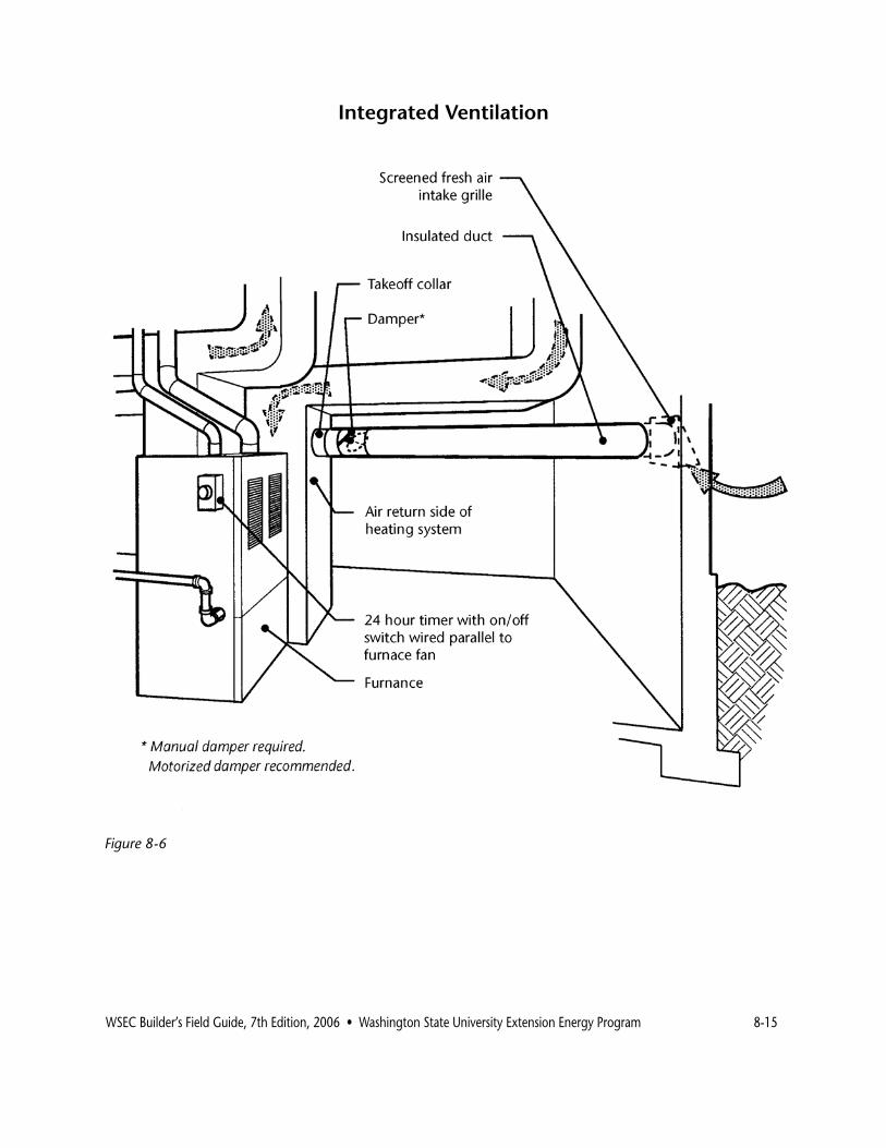
[V303.4.2] IntegratedVentilationSystem:If a forced air heating system is installed, fresh air may be ducted into the system to meet ventilation requirements (see Figure 8-6). An integrated system consists of:
• A fresh air duct, connected to the furnace return plenum, sized per VIAQ Table 3-5.
• A damper allowing the proper amount of outside air to the system.
• A clock timer set to appropriate ventilation periods.
WSEC Builder’s Field Guide, 7th Edition, 2006 • Washington State University Extension Energy Program 8-�5
IntegratedVentilation
Figure 8-6

8-�6 WSEC Builder’s Field Guide, 7th Edition, 2006 • Washington State University Extension Energy Program
[V303.4.2.�] The Code requires that the fresh air duct be connected to a terminal element outside the building and run to the return plenum within 4 feet of the air handler (see Figure 8-7). Terminal elements must be screened and sized to be greater or equal to the net free area of the duct.
VIAQ Table 3-5
Prescriptive Integrated Forced Air Supply Duct Sizing
RequiredFlow Minimum Minimum Maximum Maximum (CFM) SmoothDuct Flexible Lenght1 Numberof PerTable3-2 Diameter DuctDiameter Elbows2
50-80 6inches 7inches 20feet 3
80-125 7inches 8inches 20feet 3
115-175 8inches 10inches 20feet 3
170-240 9inches 11inches 20feet 3
1. For lenghts over 20 feet, increase duct diameter 1 inch.2. For elbows numbering more than 3, increase duct diameter 1 inch.
Terminal Element
Figure 8-7

WSEC Builder’s Field Guide, 7th Edition, 2006 • Washington State University Extension Energy Program 8-�7
[V303.4.2.�] The duct must also be equipped with a damper and three choices are given:
• A motorized damper connected to the automatic ventilation control (see Figure 8-8).
• A manual damper installed and set to meet measured flow rates in VIAQ Table 3-2.
• Or an automatic or flow-regulated device.
MotorizedDamper.When this damper is used, no testing of ventilation flow rates is required, as long as the pre-scriptive duct sizing VIAQ Table 3-5 requirements are met. Operation should be described in the required instruction manual.
DamperMeetingVIAQTable3-2FlowRates.This is a manual or volume type damper set to a certain CFM at the site. This system must either be tested or installed accord-ing to manufacturer’s installation instructions based on site conditions. Operation should be described in the required instruction manual.
AutomaticorFlow-RegulatedDevice.This type of damper refers to a constant airflow regulator, which limits airflow to a specified CFM. This device may be used when it is demonstrated, by field testing or calculation, that there is at least .07" water gauge negative pressure at the connec-tion of the outside air duct and the return air plenum must be the same size as the connecting duct work or 8 inches in diameter, whichever is larger (see Figure 8-8).

8-�8 WSEC Builder’s Field Guide, 7th Edition, 2006 • Washington State University Extension Energy Program
Types of Dampers
Figure 8-8

WSEC Builder’s Field Guide, 7th Edition, 2006 • Washington State University Extension Energy Program 8-�9
Prescriptive Requirements for Ventilation Using a Supply Fan
[V303.4.3.�] This option provides fresh air to all habitable spaces through the use of a dedicated supply fan. This system can be installed in conjunction with a forced air heating system, or as a stand alone supply air system. In both cases, duct runs are required to each habitable room.
This system provides fresh air with a smaller and quieter fan than systems integrated with forced air heating/cooling fan. This reduces ventilation energy cost.
A Ventilation System Using a Supply Fan includes:
• A Dedicated Supply Fan.• A fresh air duct, connected to the furnace supply
plenum or a dedicated whole house ventilation duct. The duct shall be sized according to VIAQ Table 3-6.
• A clock timer set to operate only the dedicated supply fan for appropriate ventilation periods.
• A filter located in fresh air supply duct, fan housing or in the case of connection to the return duct, in the furnace.
VIAQ Table 3-6
Prescriptive Supply Fan Duct Sizing
[V303.4.3]
SupplyFanTestedCFMat0.40”WG
SpecifiedVolume MinimumSmooth MinimumFlexible fromTable3-2 DuctDiameter DuctDiameter
50–90CFM 4inch 5inch
90-150CFM 5inch 6inch
150-250CFM 6inch 7inch
250-400CFM 7inch 8inch

8-20 WSEC Builder’s Field Guide, 7th Edition, 2006 • Washington State University Extension Energy Program
The supply duct must also be equipped with a damper and three choices are given:
• A motorized damper connected to the automatic ventilation control (see Figure 8-8).
• A manual damper installed and set to meet measured flow rates in VIAQ Table 3-2. (see Figure 8-8).
• An automatic or flow-regulated device. (see Figure 8-8).
MotorizedDamper.When this damper is used, no testing of ventilation flow rates is required, as long as the pre-scriptive duct sizing VIAQ Table 3-5 requirements are met. Operation should be described in the required instruction manual.
DamperMeetingVIAQTable3-2FlowRates. This is a manual or volume type damper set to a certain CFM at the site. This system must either be tested or installed accord-ing to manufacturer’s installation instructions based on site conditions. Operation of this system is required as described in the instruction manual.
AutomaticorFlow-RegulatedDevice. This type of damper refers to a constant airflow regulator, which limits airflow to a specified CFM. This device may be used when it is demonstrated, by field testing or calculation, that there is at least .07" water gauge negative pressure at the connec-tion of the outside air duct and the return air plenum must be sized using VIAQ Table 3-6. Manufacturer's instructions should be part of the required instruction manual.

WSEC Builder’s Field Guide, 7th Edition, 2006 • Washington State University Extension Energy Program 8-2�
Example of Ventilation Using a Supply Fan
Figure 8-9
Heat Recovery Ventilation
[V303.4.4] Heat recovery systems are exempt from maximum flow rates and sound rating requirements. Either air-to-air heat exchangers or exhaust air heat pumps may be used.
Air-to-air heat exchangers must meet the following requirements:
• Minimum 6 inch ducts. • Balancing dampers on the inlet and exhaust ducts.• Flow grids installed on both supply and return ducts
(for balancing).