chapter 8 { solidsunit cells must be six-sided polygons that completely ll space (no space between...
TRANSCRIPT
Chapter 8 – Solids
Introduction
Solids are characterized by an orderly arrangement of their particles. If the order is over short distances only (localorder), the solid is an amorphous solid . Charcoal and glass are amorphous solids. If the order exists throughoutthe entire solid (long range order), the solid is said to be a crystalline solid . Table salt and sugar are two commonexamples of crystalline solids. This chapter is devoted to the study of crystalline solids. Even a small crystal containsmillions and millions of particles. Thus, studying the solid state could be a formidable task.
8.1 Unit CellsIntroduction
However, the long range order that characterizes crystalline solids means that there is a small repeat unit, calledthe unit cell, that can be used to generate the entire crystal. Our study is simplified because, instead of studyingthe positions of the enormous number of particles that constitute the entire crystal, we need study only the smallnumber of particles that comprise a unit cell. In this section, we define the unit cell and discuss how it is packedwith atoms.
Objectives• Define unit cell and lattice.
8.1-1. Definition
The unit cell is the smallest repeat unit of the crystalline lattice that generates the entire lattice with translation.
Crystalline solids are orderly, repeating, 3-D arrays of particles, which can be atoms, ions, or groups of atoms,such as polyatomic ions or molecules. The pattern of the array is called the crystal lattice , and the individualpositions are called lattice sites. The simplest portion of the lattice that makes up the repeating unit is called theunit cell . When the unit cell is repeated in all three directions, it generates the entire crystalline lattice.
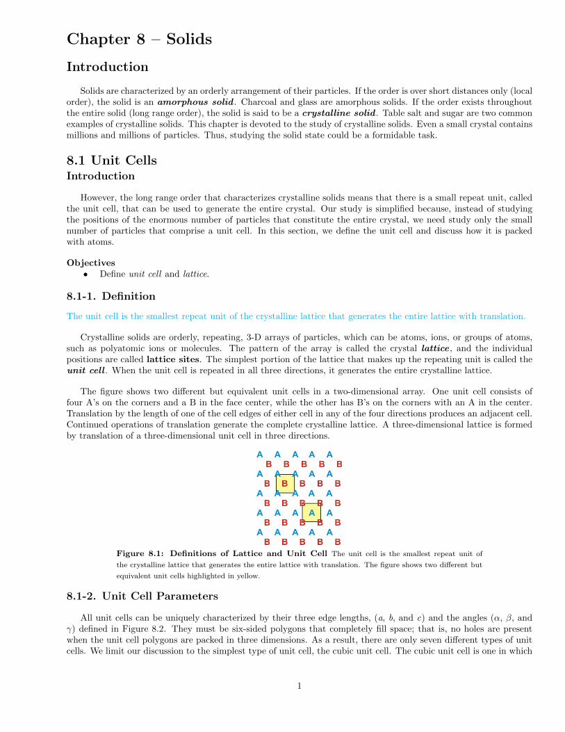
The figure shows two different but equivalent unit cells in a two-dimensional array. One unit cell consists offour A’s on the corners and a B in the face center, while the other has B’s on the corners with an A in the center.Translation by the length of one of the cell edges of either cell in any of the four directions produces an adjacent cell.Continued operations of translation generate the complete crystalline lattice. A three-dimensional lattice is formedby translation of a three-dimensional unit cell in three directions.
Figure 8.1: Definitions of Lattice and Unit Cell The unit cell is the smallest repeat unit of
the crystalline lattice that generates the entire lattice with translation. The figure shows two different but
equivalent unit cells highlighted in yellow.
8.1-2. Unit Cell Parameters
All unit cells can be uniquely characterized by their three edge lengths, (a, b, and c) and the angles (α, β, andγ) defined in Figure 8.2. They must be six-sided polygons that completely fill space; that is, no holes are presentwhen the unit cell polygons are packed in three dimensions. As a result, there are only seven different types of unitcells. We limit our discussion to the simplest type of unit cell, the cubic unit cell. The cubic unit cell is one in which
1

a = b = c and α = β = γ = 90◦. There are three types of cubic unit cells that differ only in the manner in which theparticles fill the cell.
• simple cubic (sc)• body-centered cubic (bcc)• face-centered cubic (fcc)
Figure 8.2: Parameters that Define the Unit Cell Type
8.2 Cubic Unit Cells and Metallic RadiiIntroduction
Unit cells must be six-sided polygons that completely fill space (no space between unit cells), and there are onlyseven types of unit cells that fulfill this requirement. However, our discussion is limited to only one type, the cubicunit cell.
Objectives• Distinguish between simple, body-centered, face-centered cubic unit cells.• Determine atomic radii from the unit cell edge length or the edge length from the atomic radii.
8.2-1. The Cubic Unit Cells
There are three cubic unit cells that differ in how the particles fill the cube. In each cubic unit cell, the sameatom-type occupies each of the eight corners of the cube. The unit cell type is then dictated by where else in theunit cell that atom-type is found. Note that in the images below, all spheres represent the same atom type—thecolor differences are used only to distinguish different positions in the cell. There are three different types of cubicunit cells.
Type of Cubic Unit Cell Location of Identical Particles Image
simple cubic (sc) on the corners but nowhere else in the cell
body-centered cubic (bcc) on the corners and in the center of the cell
face-centered cubic (fcc)on the corners and in the centers of thesix faces of the cell
Table 8.1: Cubic Unit Cells
2 c©2014 Advanced Instructional Systems, Inc. and NC State College of Sciences Foundation

8.2-2. Metallic or Atomic Radii
Atoms are not hard spheres with distinct boundaries, so their sizes are not determined directly. However, thepositions of the atoms in a solid can be determined by x-ray diffraction, and the sizes of the atoms are inferred fromthose distances. In this method, the radius of an atom is determined from the unit cell edge length (a), which isdetermined from the location of the atoms, and the assumption that the atoms touch as shown in Figures 8.3a, 8.3b,and 8.3c.
Figure 8.3a: Atom Contact in Simple Cubic Unit Cells
2r = a sc
Figure 8.3b: Atom Contact in Face-Centered Cubic Unit Cells
fd = 4r
fd2 = a2 + a2
(4r)2 = 2a2
fcc
Figure 8.3c: Atom Contact in Body-Centered Cubic Unit Cells
bd = 4r
bd2 = fd2 + a2
(4r)2 = 2a2 + a2 = 3a2
bcc
Setting the edge length equal to 2r in the sc unit cell, and applying the Pythagorean theorem to the trianglesshown in Figures 8.3a, 8.3b, 8.3c, we obtain the relationships between the atomic radius (r) of the atom and theedge length of the unit cell (a) given in Equation 8.1.
r =a
2(sc)
r =
√2a
4(fcc)
r =
√3a
4(bcc)
Relationship of Atomic Radii and Unit Cell Edge Lengths (8.1)
The radius obtained from the structure of a metallic solid is referred to as either the metallic radius or theatomic radius.
c©2014 Advanced Instructional Systems, Inc. and NC State College of Sciences Foundation 3
8.2-3. Determining an Atomic Radius Exercise
EXERCISE 8.1:
γ-Iron adopts a fcc crystal structure with an edge length of 3.56 A. What is the atomic radius of iron inferredfrom this structure?
r = A
8.3 Unit Cell StoichiometryIntroduction
The number of atoms or ions in a unit cell of a compound does not have to be the same as the number of atomsin the formula of the compound, but the stoichiometry of the unit cell must be the same as the stoichiometry of thecompound. Thus, a unit cell of NaCl may have many sodium and chloride ions, but the number of each ion mustbe the same because their stoichiometric ratio is 1:1 in the compound. However, when determining the unit cellstoichiometry, you cannot simply count all of the atoms or ions that form the unit because many of the particles maybe part of more than one unit cell. In this section, we explain how to determine the stoichiometry of a unit cell.
Objectives• Determine the fraction of an atom that lies in a unit cell given the lattice site occupied by the atom.• Determine the number of atoms, molecules, or ions in a unit cell.
8.3-1. Unit Cells Share Particles
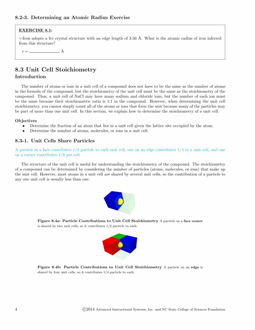
A particle in a face contributes 1/2 particle to each unit cell, one on an edge contributes 1/4 to a unit cell, and oneon a corner contributes 1/8 per cell.
The structure of the unit cell is useful for understanding the stoichiometry of the compound. The stoichiometryof a compound can be determined by considering the number of particles (atoms, molecules, or ions) that make upthe unit cell. However, most atoms in a unit cell are shared by several unit cells, so the contribution of a particle toany one unit cell is usually less than one.
Figure 8.4a: Particle Contributions to Unit Cell Stoichiometry A particle on a face center
is shared by two unit cells, so it contributes 1/2 particle to each.
Figure 8.4b: Particle Contributions to Unit Cell Stoichiometry A particle on an edge is
shared by four unit cells, so it contributes 1/4 particle to each.
4 c©2014 Advanced Instructional Systems, Inc. and NC State College of Sciences Foundation
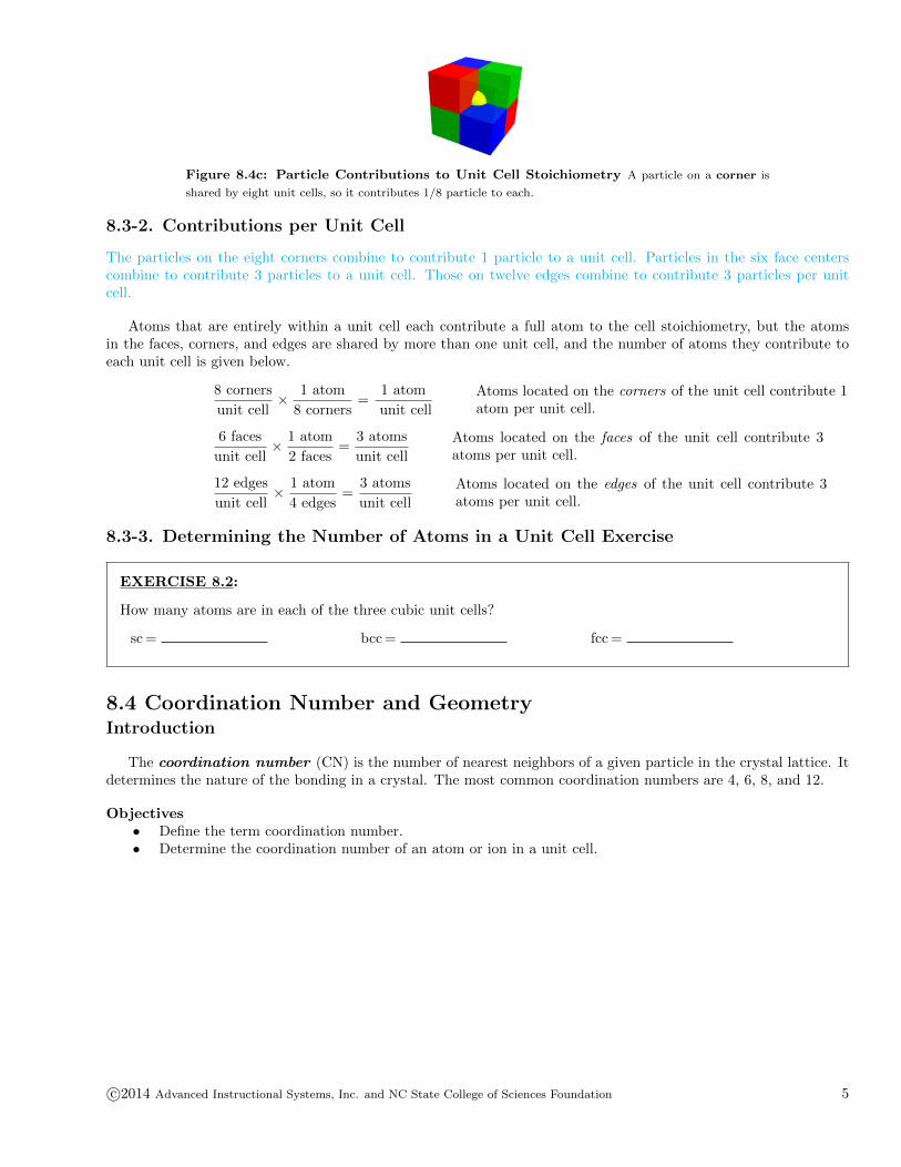
Figure 8.4c: Particle Contributions to Unit Cell Stoichiometry A particle on a corner is
shared by eight unit cells, so it contributes 1/8 particle to each.
8.3-2. Contributions per Unit Cell
The particles on the eight corners combine to contribute 1 particle to a unit cell. Particles in the six face centerscombine to contribute 3 particles to a unit cell. Those on twelve edges combine to contribute 3 particles per unitcell.
Atoms that are entirely within a unit cell each contribute a full atom to the cell stoichiometry, but the atomsin the faces, corners, and edges are shared by more than one unit cell, and the number of atoms they contribute toeach unit cell is given below.
8 corners
unit cell× 1 atom
8 corners=
1 atom
unit cell
Atoms located on the corners of the unit cell contribute 1atom per unit cell.
6 faces
unit cell× 1 atom
2 faces=
3 atoms
unit cell
Atoms located on the faces of the unit cell contribute 3atoms per unit cell.
12 edges
unit cell× 1 atom
4 edges=
3 atoms
unit cell
Atoms located on the edges of the unit cell contribute 3atoms per unit cell.
8.3-3. Determining the Number of Atoms in a Unit Cell Exercise
EXERCISE 8.2:
How many atoms are in each of the three cubic unit cells?
sc = bcc = fcc =
8.4 Coordination Number and GeometryIntroduction
The coordination number (CN) is the number of nearest neighbors of a given particle in the crystal lattice. Itdetermines the nature of the bonding in a crystal. The most common coordination numbers are 4, 6, 8, and 12.
Objectives• Define the term coordination number.• Determine the coordination number of an atom or ion in a unit cell.
c©2014 Advanced Instructional Systems, Inc. and NC State College of Sciences Foundation 5
8.4-1. Common Coordination Numbers and their Geometries
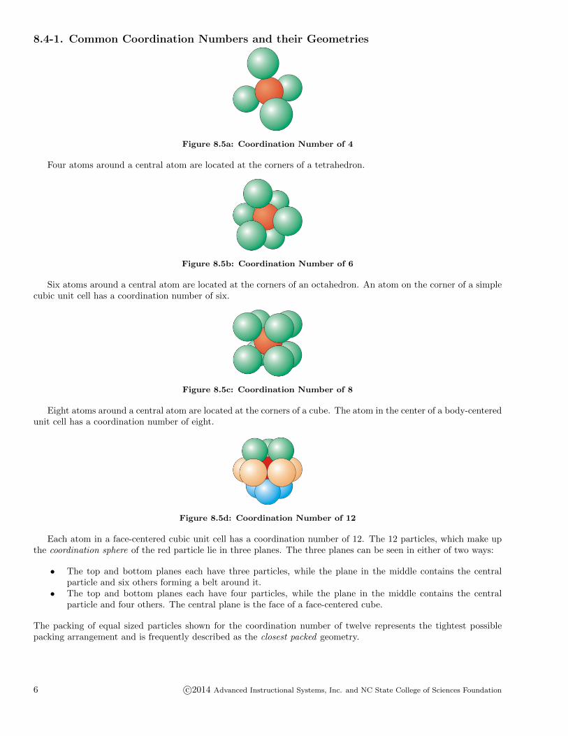
Figure 8.5a: Coordination Number of 4
Four atoms around a central atom are located at the corners of a tetrahedron.
Figure 8.5b: Coordination Number of 6
Six atoms around a central atom are located at the corners of an octahedron. An atom on the corner of a simplecubic unit cell has a coordination number of six.
Figure 8.5c: Coordination Number of 8
Eight atoms around a central atom are located at the corners of a cube. The atom in the center of a body-centeredunit cell has a coordination number of eight.
Figure 8.5d: Coordination Number of 12
Each atom in a face-centered cubic unit cell has a coordination number of 12. The 12 particles, which make upthe coordination sphere of the red particle lie in three planes. The three planes can be seen in either of two ways:
• The top and bottom planes each have three particles, while the plane in the middle contains the centralparticle and six others forming a belt around it.
• The top and bottom planes each have four particles, while the plane in the middle contains the centralparticle and four others. The central plane is the face of a face-centered cube.
The packing of equal sized particles shown for the coordination number of twelve represents the tightest possiblepacking arrangement and is frequently described as the closest packed geometry.
6 c©2014 Advanced Instructional Systems, Inc. and NC State College of Sciences Foundation
8.4-2. Coordination Number Exercise
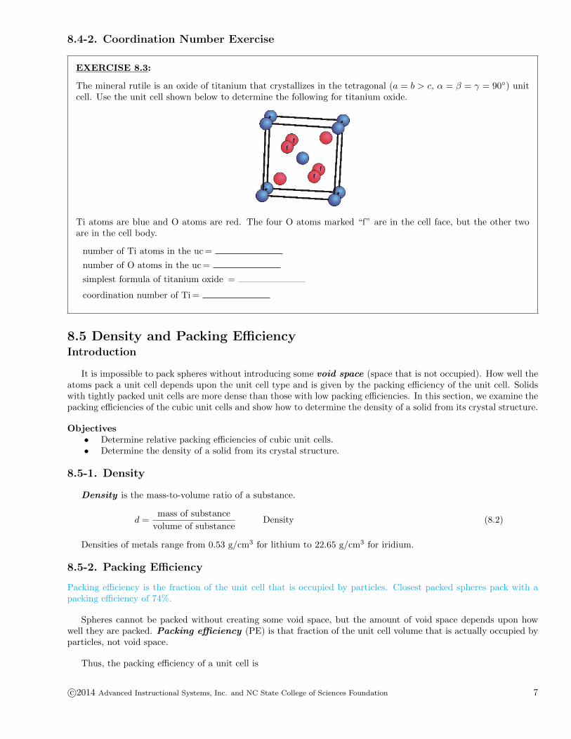
EXERCISE 8.3:
The mineral rutile is an oxide of titanium that crystallizes in the tetragonal (a = b > c, α = β = γ = 90◦) unitcell. Use the unit cell shown below to determine the following for titanium oxide.
Ti atoms are blue and O atoms are red. The four O atoms marked “f” are in the cell face, but the other twoare in the cell body.
number of Ti atoms in the uc =
number of O atoms in the uc =
simplest formula of titanium oxide =
coordination number of Ti =
8.5 Density and Packing EfficiencyIntroduction
It is impossible to pack spheres without introducing some void space (space that is not occupied). How well theatoms pack a unit cell depends upon the unit cell type and is given by the packing efficiency of the unit cell. Solidswith tightly packed unit cells are more dense than those with low packing efficiencies. In this section, we examine thepacking efficiencies of the cubic unit cells and show how to determine the density of a solid from its crystal structure.
Objectives• Determine relative packing efficiencies of cubic unit cells.• Determine the density of a solid from its crystal structure.
8.5-1. Density
Density is the mass-to-volume ratio of a substance.
d =mass of substance
volume of substanceDensity (8.2)
Densities of metals range from 0.53 g/cm3 for lithium to 22.65 g/cm3 for iridium.
8.5-2. Packing Efficiency
Packing efficiency is the fraction of the unit cell that is occupied by particles. Closest packed spheres pack with apacking efficiency of 74%.
Spheres cannot be packed without creating some void space, but the amount of void space depends upon howwell they are packed. Packing efficiency (PE) is that fraction of the unit cell volume that is actually occupied byparticles, not void space.
Thus, the packing efficiency of a unit cell is
c©2014 Advanced Instructional Systems, Inc. and NC State College of Sciences Foundation 7
Packing Efficiency =volume of atoms
volume of unit cell× 100%
PE =N × (4/3)πr3
a3× 100%
(8.3)
• a = the length of a side of the unit cell, so a3 is the volume of the unit cell.• r = the radius of the atoms that occupy the unit cell, so (4/3)πr3 is the volume of a single atom in the unit
cell.• N = the number of atoms in the unit cell, so N (4/3)πr3 is the volume occupied by all of the atoms in the
unit cell.
The unit cell size (a) is directly proportional to the atom size (r), so one can be defined in terms of the other andthen canceled in the above expression. Consequently, the packing efficiency depends only upon the cell type, not itssize. As shown in the next sections, the relationship between a and r depends only upon the unit cell type.
8.5-3. Packing in Simple Cubes
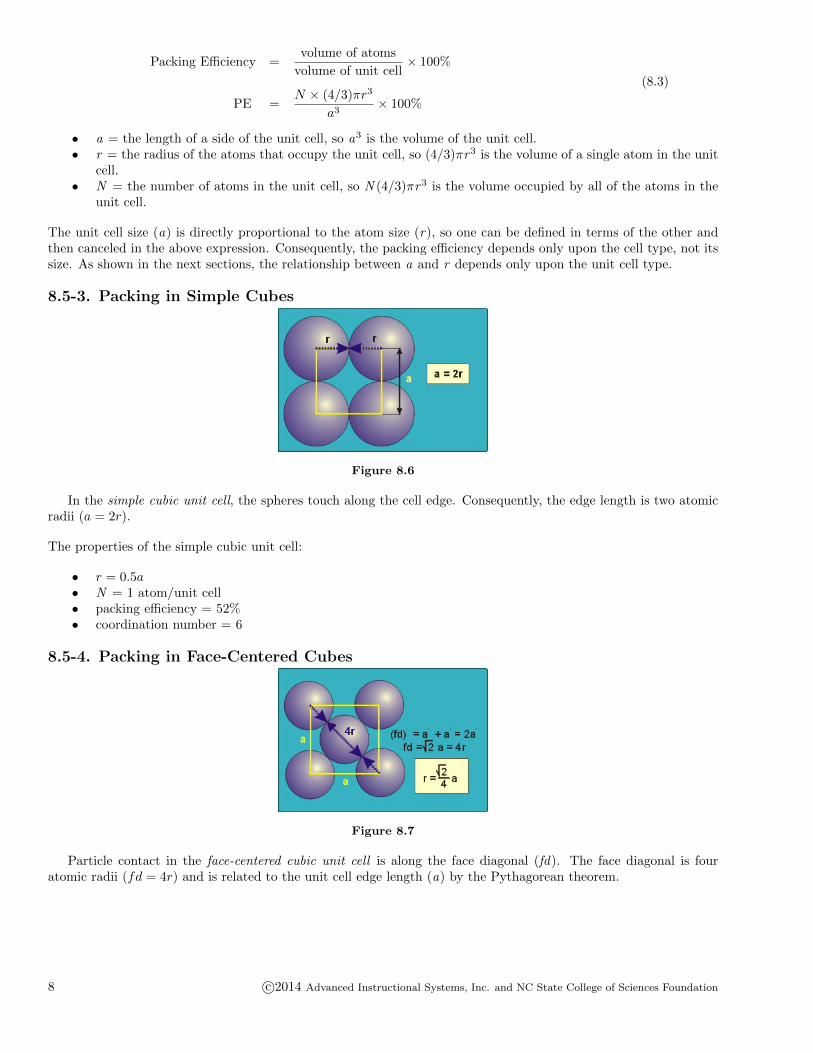
Figure 8.6
In the simple cubic unit cell, the spheres touch along the cell edge. Consequently, the edge length is two atomicradii (a = 2r).
The properties of the simple cubic unit cell:
• r = 0.5a• N = 1 atom/unit cell• packing efficiency = 52%• coordination number = 6
8.5-4. Packing in Face-Centered Cubes
Figure 8.7
Particle contact in the face-centered cubic unit cell is along the face diagonal (fd). The face diagonal is fouratomic radii (fd = 4r) and is related to the unit cell edge length (a) by the Pythagorean theorem.
8 c©2014 Advanced Instructional Systems, Inc. and NC State College of Sciences Foundation
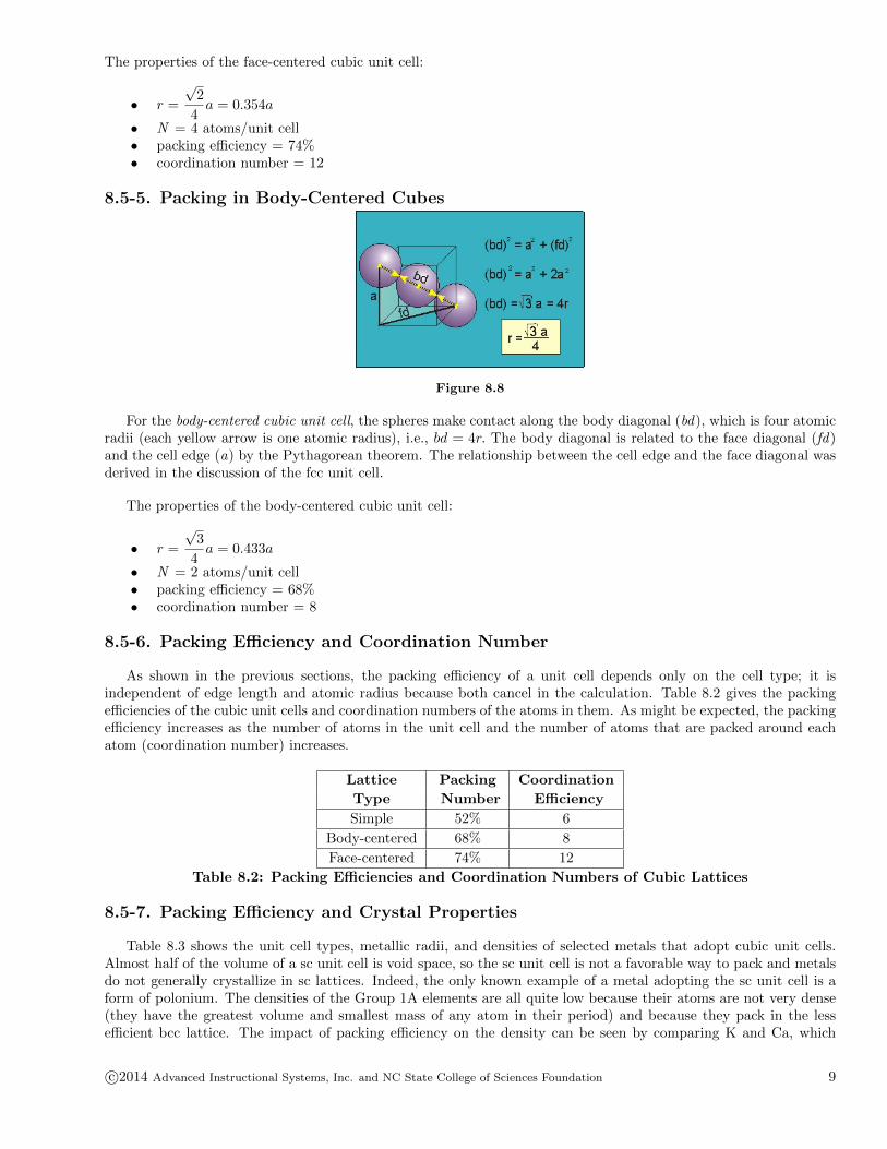
The properties of the face-centered cubic unit cell:
• r =
√2
4a = 0.354a
• N = 4 atoms/unit cell• packing efficiency = 74%• coordination number = 12
8.5-5. Packing in Body-Centered Cubes
Figure 8.8
For the body-centered cubic unit cell, the spheres make contact along the body diagonal (bd), which is four atomicradii (each yellow arrow is one atomic radius), i.e., bd = 4r. The body diagonal is related to the face diagonal (fd)and the cell edge (a) by the Pythagorean theorem. The relationship between the cell edge and the face diagonal wasderived in the discussion of the fcc unit cell.
The properties of the body-centered cubic unit cell:
• r =
√3
4a = 0.433a
• N = 2 atoms/unit cell• packing efficiency = 68%• coordination number = 8
8.5-6. Packing Efficiency and Coordination Number
As shown in the previous sections, the packing efficiency of a unit cell depends only on the cell type; it isindependent of edge length and atomic radius because both cancel in the calculation. Table 8.2 gives the packingefficiencies of the cubic unit cells and coordination numbers of the atoms in them. As might be expected, the packingefficiency increases as the number of atoms in the unit cell and the number of atoms that are packed around eachatom (coordination number) increases.
Lattice Packing Coordination
Type Number Efficiency
Simple 52% 6
Body-centered 68% 8
Face-centered 74% 12
Table 8.2: Packing Efficiencies and Coordination Numbers of Cubic Lattices
8.5-7. Packing Efficiency and Crystal Properties
Table 8.3 shows the unit cell types, metallic radii, and densities of selected metals that adopt cubic unit cells.Almost half of the volume of a sc unit cell is void space, so the sc unit cell is not a favorable way to pack and metalsdo not generally crystallize in sc lattices. Indeed, the only known example of a metal adopting the sc unit cell is aform of polonium. The densities of the Group 1A elements are all quite low because their atoms are not very dense(they have the greatest volume and smallest mass of any atom in their period) and because they pack in the lessefficient bcc lattice. The impact of packing efficiency on the density can be seen by comparing K and Ca, which
c©2014 Advanced Instructional Systems, Inc. and NC State College of Sciences Foundation 9
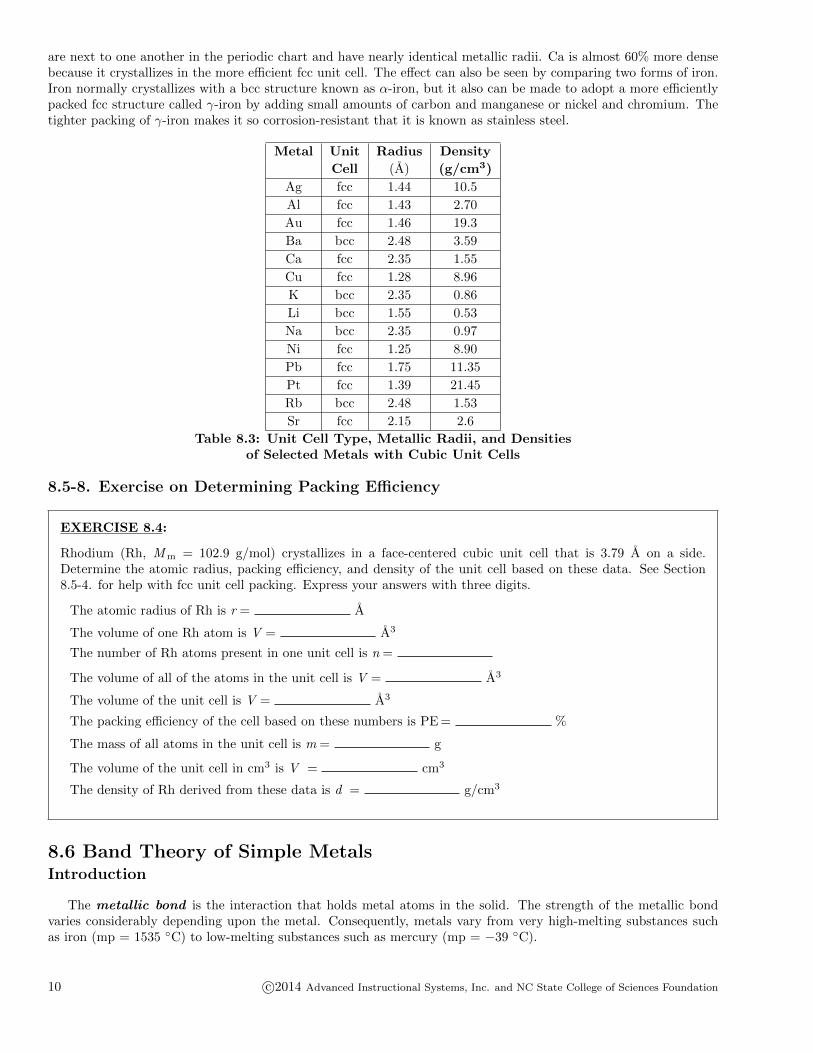
are next to one another in the periodic chart and have nearly identical metallic radii. Ca is almost 60% more densebecause it crystallizes in the more efficient fcc unit cell. The effect can also be seen by comparing two forms of iron.Iron normally crystallizes with a bcc structure known as α-iron, but it also can be made to adopt a more efficientlypacked fcc structure called γ-iron by adding small amounts of carbon and manganese or nickel and chromium. Thetighter packing of γ-iron makes it so corrosion-resistant that it is known as stainless steel.
Metal Unit Radius Density
Cell (A) (g/cm3)
Ag fcc 1.44 10.5
Al fcc 1.43 2.70
Au fcc 1.46 19.3
Ba bcc 2.48 3.59
Ca fcc 2.35 1.55
Cu fcc 1.28 8.96
K bcc 2.35 0.86
Li bcc 1.55 0.53
Na bcc 2.35 0.97
Ni fcc 1.25 8.90
Pb fcc 1.75 11.35
Pt fcc 1.39 21.45
Rb bcc 2.48 1.53
Sr fcc 2.15 2.6
Table 8.3: Unit Cell Type, Metallic Radii, and Densitiesof Selected Metals with Cubic Unit Cells
8.5-8. Exercise on Determining Packing Efficiency
EXERCISE 8.4:
Rhodium (Rh, Mm = 102.9 g/mol) crystallizes in a face-centered cubic unit cell that is 3.79 A on a side.Determine the atomic radius, packing efficiency, and density of the unit cell based on these data. See Section8.5-4. for help with fcc unit cell packing. Express your answers with three digits.
The atomic radius of Rh is r = A
The volume of one Rh atom is V = A3
The number of Rh atoms present in one unit cell is n =
The volume of all of the atoms in the unit cell is V = A3
The volume of the unit cell is V = A3
The packing efficiency of the cell based on these numbers is PE = %
The mass of all atoms in the unit cell is m = g
The volume of the unit cell in cm3 is V = cm3
The density of Rh derived from these data is d = g/cm3
8.6 Band Theory of Simple MetalsIntroduction
The metallic bond is the interaction that holds metal atoms in the solid. The strength of the metallic bondvaries considerably depending upon the metal. Consequently, metals vary from very high-melting substances suchas iron (mp = 1535 ◦C) to low-melting substances such as mercury (mp = −39 ◦C).
10 c©2014 Advanced Instructional Systems, Inc. and NC State College of Sciences Foundation
Metals have low ionization energies and readily lose their valence electrons to become positively charged ions. Ina metallic bond, valence electrons from all of the metal atoms in the solid are delocalized over the entire metal. Themetal cations are immersed in the sea of valence electrons, and the electrostatic force exerted between the cationsand the surrounding electrons holds the positively charged metal ions in place.
Bonding and electrical conduction in metals is best understood in terms of band theory , which is the extensionof molecular orbital theory (Section 6.5) to the very large number of atoms found in a metal.
Objectives• Describe a metallic bond.• Explain what is meant by an energy band.• Define the Fermi level and identify it in a band diagram.• Explain how a metal can be a conductor even when all of its valence orbitals are full.• Define the band gap.• Distinguish between a valence band and a conduction band.• Distinguish between a metallic conductor, a semiconductor, and an insulator based on their band structures.
8.6-1. Introduction to Band Theory
The molecular orbital description of the delocalized electrons in metallic bonds provides a more complete pictureof metallic bonding as well as an explanation for the electrical conductivity of metals. The explanation, which iscalled band theory, applies the concepts presented in the molecular orbital discussion in Chapter 6 to a very largenumber of orbitals. The orbitals in the solid are constructed in the same way as those in a molecule, but they applyto a crystal rather than a molecule, so they are called crystal orbitals rather than molecular orbitals. As the numberof orbitals increases, the adjacent orbitals become more similar, and the resulting energy levels get closer together.In a piece of metal, the number of atoms and atomic orbitals in each crystal orbital is enormous (on the order ofAvogadro’s number), so the energy levels are so close that they can no longer be distinguished and the system isdescribed in terms of energy bands rather than energy levels. The formation and properties of bands is the topic ofthis section.
8.6-2. Properties of Multi-Orbital Systems
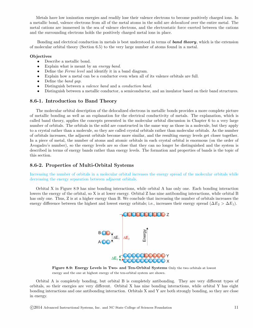
Increasing the number of orbitals in a molecular orbital increases the energy spread of the molecular orbitals whiledecreasing the energy separation between adjacent orbitals.
Orbital X in Figure 8.9 has nine bonding interactions, while orbital A has only one. Each bonding interactionlowers the energy of the orbital, so X is at lower energy. Orbital Z has nine antibonding interactions, while orbital Bhas only one. Thus, Z is at a higher energy than B. We conclude that increasing the number of orbitals increases theenergy difference between the highest and lowest energy orbitals; i.e., increases their energy spread (∆E 2 > ∆E 1).
Figure 8.9: Energy Levels in Two- and Ten-Orbital Systems Only the two orbitals at lowest
energy and the one at highest energy of the ten-orbital system are shown.
Orbital A is completely bonding, but orbital B is completely antibonding. They are very different types oforbitals, so their energies are very different. Orbital X has nine bonding interactions, while orbital Y has eightbonding interactions and one antibonding interaction. Orbitals X and Y are both strongly bonding, so they are closein energy.
c©2014 Advanced Instructional Systems, Inc. and NC State College of Sciences Foundation 11
8.6-3. The Definition of a Band
The energy levels in a metal are so close that they are represented by a band of energy.
As the number of orbitals increases, the energy spread of the molecular orbitals continues to increase, while theenergy separation between adjacent levels continues to decrease. In a piece of metal, the number of atoms andorbitals is so large (on the order of Avogadro’s number) that the energy levels are so close that they can no longer bedistinguished. At this point, the energy levels are said to form an energy band . Energy bands are represented byrectangles that show the spread in energy between the lowest and highest energy orbitals. Although the separationbetween levels is so small that discreet levels are not shown, they do exist and the electrons fill the levels in a bandwith the same rules as they do the levels in an atom (lowest energy, Pauli Exclusion Principle).
Figure 8.10: Band Formation The dotted lines represent the energy spread and show that the top
and bottom energies begin to level off as the number of orbitals gets large.
8.6-4. Fermi Level
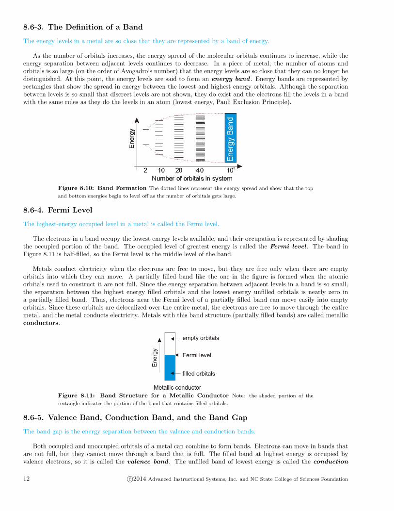
The highest-energy occupied level in a metal is called the Fermi level.
The electrons in a band occupy the lowest energy levels available, and their occupation is represented by shadingthe occupied portion of the band. The occupied level of greatest energy is called the Fermi level . The band inFigure 8.11 is half-filled, so the Fermi level is the middle level of the band.
Metals conduct electricity when the electrons are free to move, but they are free only when there are emptyorbitals into which they can move. A partially filled band like the one in the figure is formed when the atomicorbitals used to construct it are not full. Since the energy separation between adjacent levels in a band is so small,the separation between the highest energy filled orbitals and the lowest energy unfilled orbitals is nearly zero ina partially filled band. Thus, electrons near the Fermi level of a partially filled band can move easily into emptyorbitals. Since these orbitals are delocalized over the entire metal, the electrons are free to move through the entiremetal, and the metal conducts electricity. Metals with this band structure (partially filled bands) are called metallicconductors.
Figure 8.11: Band Structure for a Metallic Conductor Note: the shaded portion of the
rectangle indicates the portion of the band that contains filled orbitals.
8.6-5. Valence Band, Conduction Band, and the Band Gap
The band gap is the energy separation between the valence and conduction bands.
Both occupied and unoccupied orbitals of a metal can combine to form bands. Electrons can move in bands thatare not full, but they cannot move through a band that is full. The filled band at highest energy is occupied byvalence electrons, so it is called the valence band . The unfilled band of lowest energy is called the conduction
12 c©2014 Advanced Instructional Systems, Inc. and NC State College of Sciences Foundation

band because it is the band in which electrons are free to move. The energy separation between the valence andconduction band is called the band gap. As we show in the next section, the conductivity properties of the metalare determined by the magnitude of the band gap.
Figure 8.12: The Band Gap
8.6-6. Conductivity
Conductors have no band gap, semiconductors have moderate band gaps, and insulators have large band gaps.
The electrical conductivity properties of a metal depend upon its band gap.
Figure 8.13
Metallic conductors have partially filled bands, so they have no band gap. Bands at higher energy are irrelevantto their conductivity.
c©2014 Advanced Instructional Systems, Inc. and NC State College of Sciences Foundation 13

Figure 8.14
Semiconductors have band gaps that are not zero but are small enough that the conduction band can bepopulated at reasonable temperatures. The conductivity of semiconductors increases as the temperature is increasedbecause the number of electrons in the conduction band increases as their thermal energy increases.
Figure 8.15
Insulators have band gaps that are so large that no electrons can occupy the conduction band at reasonabletemperatures.
8.6-7. Band Overlap
A metal with filled orbitals can be a conductor if the bottom of a band formed from empty orbitals overlaps the topof the band formed from filled orbitals.
Metals with no unfilled orbitals can contain partially filled bands if the band formed from the filled atomic orbitalsoverlaps with a band formed from empty orbitals. This is the reason that metallic elements, such as zinc, that haveno partially filled orbitals in their atoms can still be conductors. For example, Figure 8.16 shows the band structureof zinc. The filled 4s band and the unoccupied 4p band overlap, so the highest energy electrons in the 4s bandmove to lower energy in the 4p band to produce two partially filled bands. The partially filled bands make zinc aconductor.
14 c©2014 Advanced Instructional Systems, Inc. and NC State College of Sciences Foundation
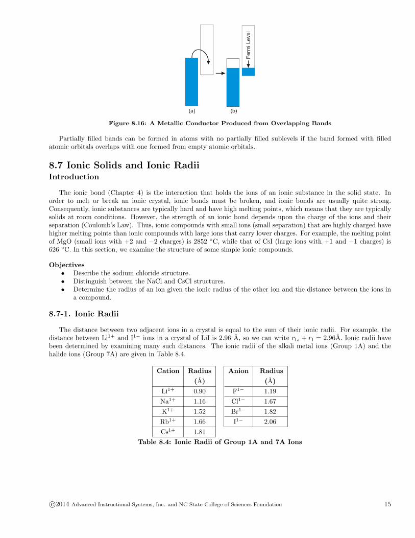
Figure 8.16: A Metallic Conductor Produced from Overlapping Bands
Partially filled bands can be formed in atoms with no partially filled sublevels if the band formed with filledatomic orbitals overlaps with one formed from empty atomic orbitals.
8.7 Ionic Solids and Ionic RadiiIntroduction
The ionic bond (Chapter 4) is the interaction that holds the ions of an ionic substance in the solid state. Inorder to melt or break an ionic crystal, ionic bonds must be broken, and ionic bonds are usually quite strong.Consequently, ionic substances are typically hard and have high melting points, which means that they are typicallysolids at room conditions. However, the strength of an ionic bond depends upon the charge of the ions and theirseparation (Coulomb’s Law). Thus, ionic compounds with small ions (small separation) that are highly charged havehigher melting points than ionic compounds with large ions that carry lower charges. For example, the melting pointof MgO (small ions with +2 and −2 charges) is 2852 ◦C, while that of CsI (large ions with +1 and −1 charges) is626 ◦C. In this section, we examine the structure of some simple ionic compounds.
Objectives• Describe the sodium chloride structure.• Distinguish between the NaCl and CsCl structures.• Determine the radius of an ion given the ionic radius of the other ion and the distance between the ions in
a compound.
8.7-1. Ionic Radii
The distance between two adjacent ions in a crystal is equal to the sum of their ionic radii. For example, thedistance between Li1+ and I1− ions in a crystal of LiI is 2.96 A, so we can write rLi + rI = 2.96A. Ionic radii havebeen determined by examining many such distances. The ionic radii of the alkali metal ions (Group 1A) and thehalide ions (Group 7A) are given in Table 8.4.
Cation Radius Anion Radius
(A) (A)
Li1+ 0.90 F1− 1.19
Na1+ 1.16 Cl1− 1.67
K1+ 1.52 Br1− 1.82
Rb1+ 1.66 I1− 2.06
Cs1+ 1.81
Table 8.4: Ionic Radii of Group 1A and 7A Ions
c©2014 Advanced Instructional Systems, Inc. and NC State College of Sciences Foundation 15

8.7-2. Ionic Radii Exercise
EXERCISE 8.5:
What is the ionic radius of Mg2+, if the Mg–Cl distance in MgCl2 is 2.53 A?
the ionic radius of Cl1− from Table 8.4 = A
rMg = A
8.7-3. LiI
Not all of the particles in an ionic solid are identical, but the same structural descriptions that are applied tometallic solids can be used to understand the crystal structure of many ionic compounds. For example, most of thealkali halides have a preference for a structure in which the anions pack in a face-centered cubic unit cell, as shownin Figure 8.17a, with the cations filling the void space as in Figure 8.17b.
Figure 8.17
The three anions along a diagonal of a face touch in a fcc unit cell, but there is void space along each of thecell edges and in the body center and much smaller cations fill the space. Using geometry, we can calculate thatto fill the void space perfectly, the radius of the cation should be a little less than half the radius of the anion(rcation = 0.414ranion).
LiI nearly adopts the ideal structure (rLi/r I = 0.44) and has a very high packing efficiency. However, the Li1+
ions are slightly too large to fit into the holes, so the I1− ions are pushed apart slightly, so they no longer makecontact.
8.7-4. LiCl
Figure 8.18: LiCl Unit Cell
Chloride ions are smaller than iodide ions, so their fcc arrangement has even smaller holes along the edge.Consequently, they must be pushed apart even farther to accommodate the Li1+ ions (Figure 8.18). The distanceby which the chloride ions are separated is determined in the following exercise.
16 c©2014 Advanced Instructional Systems, Inc. and NC State College of Sciences Foundation
8.7-5. Packing Exercise
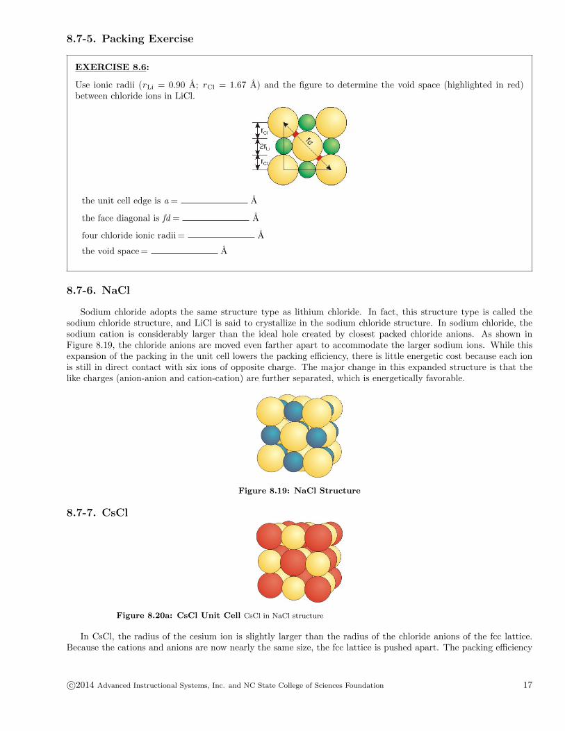
EXERCISE 8.6:
Use ionic radii (rLi = 0.90 A; rCl = 1.67 A) and the figure to determine the void space (highlighted in red)between chloride ions in LiCl.
the unit cell edge is a = A
the face diagonal is fd = A
four chloride ionic radii = A
the void space = A
8.7-6. NaCl
Sodium chloride adopts the same structure type as lithium chloride. In fact, this structure type is called thesodium chloride structure, and LiCl is said to crystallize in the sodium chloride structure. In sodium chloride, thesodium cation is considerably larger than the ideal hole created by closest packed chloride anions. As shown inFigure 8.19, the chloride anions are moved even farther apart to accommodate the larger sodium ions. While thisexpansion of the packing in the unit cell lowers the packing efficiency, there is little energetic cost because each ionis still in direct contact with six ions of opposite charge. The major change in this expanded structure is that thelike charges (anion-anion and cation-cation) are further separated, which is energetically favorable.
Figure 8.19: NaCl Structure
8.7-7. CsCl
Figure 8.20a: CsCl Unit Cell CsCl in NaCl structure
In CsCl, the radius of the cesium ion is slightly larger than the radius of the chloride anions of the fcc lattice.Because the cations and anions are now nearly the same size, the fcc lattice is pushed apart. The packing efficiency
c©2014 Advanced Instructional Systems, Inc. and NC State College of Sciences Foundation 17
drops down to that of a simple cube in which four of the corners are occupied by cations and four are occupied byanions. CsCl can be made to crystallize with the sodium chloride only under certain conditions.
Figure 8.20b: CsCl Unit Cell The CsCl structure
Under normal conditions, the packing efficiency of these nearly equally sized ions is optimized in the arrangement,as shown in the figure. This structure, known as the cesium chloride structure, can be described as having chlorideanions forming a simple cube with a cesium cation in the body center. Alternatively, it can be described as a simplecube of cesium cations with a chloride anion in the body center.
8.8 Network Covalent SolidsIntroduction
Covalent solids are like ionic solids in that they are very large networks of particles rather than discrete molecules.They differ from ionic solids in that the particles are atoms, not ions, and they are held in their lattice sites by covalentbonds rather than ionic bonds. Because the atoms in the lattice are attached by strong covalent bonds, the materialshave very high melting points and are very hard. In this section, we examine the structures of several commonnetwork covalent solids.
Objectives• Describe the structure of graphite and explain why graphite is a lubricant.• Describe the structures of diamond and the semiconductors Si and Ge.• Describe the similarity between the structure of diamond and the semiconductors ZnS, GaAs, and IP.
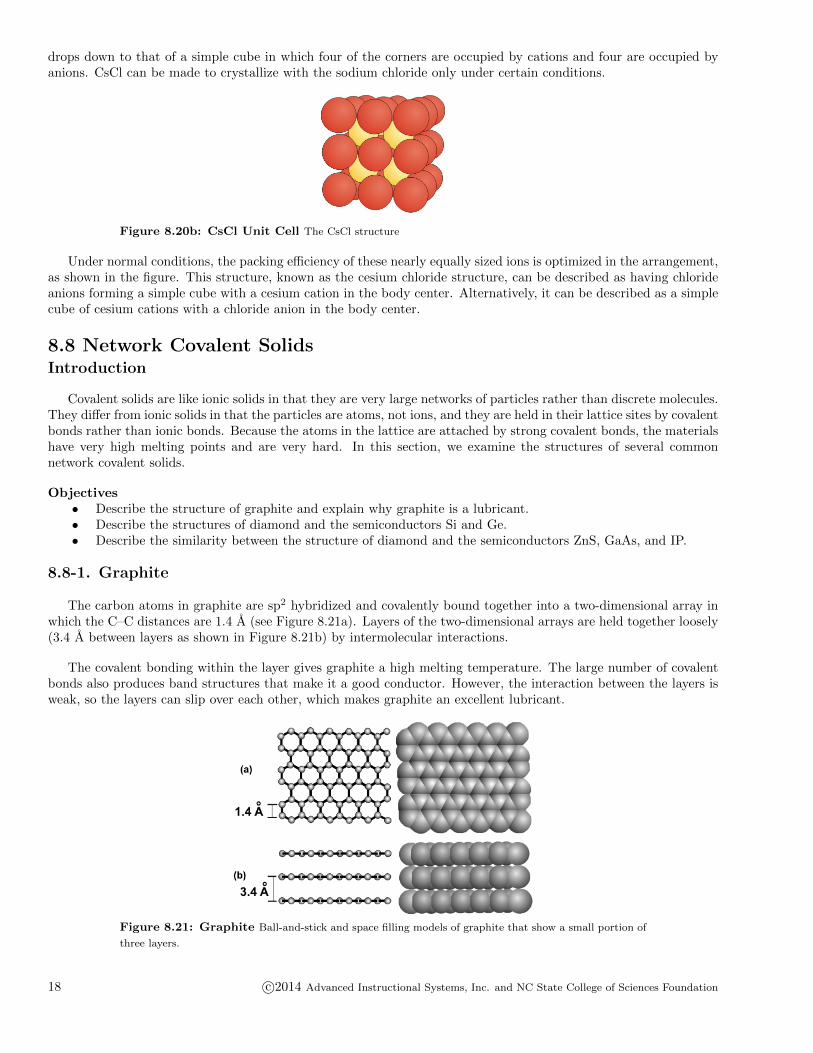
8.8-1. Graphite
The carbon atoms in graphite are sp2 hybridized and covalently bound together into a two-dimensional array inwhich the C–C distances are 1.4 A (see Figure 8.21a). Layers of the two-dimensional arrays are held together loosely(3.4 A between layers as shown in Figure 8.21b) by intermolecular interactions.
The covalent bonding within the layer gives graphite a high melting temperature. The large number of covalentbonds also produces band structures that make it a good conductor. However, the interaction between the layers isweak, so the layers can slip over each other, which makes graphite an excellent lubricant.
Figure 8.21: Graphite Ball-and-stick and space filling models of graphite that show a small portion of
three layers.
18 c©2014 Advanced Instructional Systems, Inc. and NC State College of Sciences Foundation

8.8-2. Buckyball
Fullerenes are carbon compounds with structures based on the graphite structure. The most common fullereneis C60, which is called buckminster-fullerene (or buckyball) after the architect of the geodesic dome. Buckyball wasdiscovered in the early 1980’s. It contains 20 hexagons and 12 pentagons and is the shape of a soccer ball. Thehexagons are the same units that form the basis of graphite, but the pentagons are required for closure. A greatdeal of research was done on fullerenes to develop new technologies. For example, efforts were made to use it as amolecular ball-bearing lubricant, and to encapsulate drugs in its cavity, so they could be released slowly in the body.Buckyball is also a superconductor, so efforts were made to take advantage of this property as well. However, nopractical uses of buckyball have yet been developed.
Figure 8.22: Buckyball Figure (a) shows the stick model of Buckyball that includes only the bonds
to emphasize the hexagons and pentagons. Figure (b) is the ball-and-stick model that includes the carbon
atoms.
8.8-3. Nanotubes
Nanotubes are based on the graphite structure. They are basic building blocks in molecular electronics.
A carbon nanotube is a rolled-up sheet of graphite that is only nanometers wide but up to a centimeter long.Nanotubes are very strong, and, depending on how the graphite sheets are rolled (straight across or at a diagonal),they are conductors or semiconductors. Single nanotubes have been used to make molecular wires, diodes, andtransistors, and groups of nanotubes have been integrated into logic circuits, fundamental computer components.These devices are a hundred times smaller than those on present-day computer chips. Nanotubes are a basic buildingblock in the new field of molecular electronics. Indeed, a new technology, one based on devices that measure lessthan 1000 nanometers, is currently being developed. This new technology is referred to as nanotechnology.
Figure 8.23: Nanotube The tube is viewed down its axis in a and along its side in b.
8.8-4. Diamond
Its strong bonds and structure make diamond the strongest substance known.
Directional sp3 hybridized orbitals are used to create the three-dimensional framework of diamond. The directionalbonds result in a much lower packing efficiency than in metals or ionic compounds where the spherical nature of theatoms and ions allows for much tighter packing. The figure shows one unit cell.
c©2014 Advanced Instructional Systems, Inc. and NC State College of Sciences Foundation 19
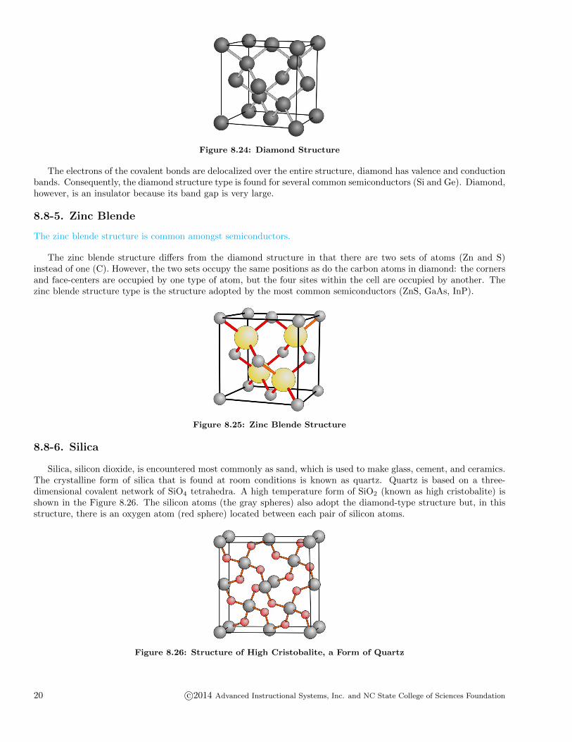
Figure 8.24: Diamond Structure
The electrons of the covalent bonds are delocalized over the entire structure, diamond has valence and conductionbands. Consequently, the diamond structure type is found for several common semiconductors (Si and Ge). Diamond,however, is an insulator because its band gap is very large.
8.8-5. Zinc Blende
The zinc blende structure is common amongst semiconductors.
The zinc blende structure differs from the diamond structure in that there are two sets of atoms (Zn and S)instead of one (C). However, the two sets occupy the same positions as do the carbon atoms in diamond: the cornersand face-centers are occupied by one type of atom, but the four sites within the cell are occupied by another. Thezinc blende structure type is the structure adopted by the most common semiconductors (ZnS, GaAs, InP).
Figure 8.25: Zinc Blende Structure
8.8-6. Silica
Silica, silicon dioxide, is encountered most commonly as sand, which is used to make glass, cement, and ceramics.The crystalline form of silica that is found at room conditions is known as quartz. Quartz is based on a three-dimensional covalent network of SiO4 tetrahedra. A high temperature form of SiO2 (known as high cristobalite) isshown in the Figure 8.26. The silicon atoms (the gray spheres) also adopt the diamond-type structure but, in thisstructure, there is an oxygen atom (red sphere) located between each pair of silicon atoms.
Figure 8.26: Structure of High Cristobalite, a Form of Quartz
20 c©2014 Advanced Instructional Systems, Inc. and NC State College of Sciences Foundation

8.8-7. Zeolite Structure
Zeolites are characterized by molecular scale channels.
Natural zeolites are aluminosilicates, extended networks that are built from tetrahedral AlO4 and SiO4 units thatare bridged by oxygen atoms (each oxygen atom is part of two units). The structure of zeolites is filled with cavities(pores) and channels that are only a few angstroms wide (1 angstrom = 10 nm). The aluminosilicate framework isanionic, so natural zeolites are commonly found as their sodium salts. The cations sit inside the cavities. Smallmolecules can also get into the channels and interact with the oxygen atoms in the aluminosilicate framework, whichleads to many uses for zeolites.
Figure 8.27: Zeolite (a) A section of a zeolite showing a series of channels. Al or Si atoms sit at the
end of each line with O atoms bridging them. The openings in the structure that are too small for other
molecules to enter are shown as closed surfaces. (b) The pore of this zeolite is formed by a ring that contains
12 atoms (Si and Al) and is 7 A in diameter. A benzene molecule, which is about 4 A across, is shown for
comparison.
8.8-8. Zeolite Function
Molecular sieves
• The interaction between small molecules in the cavities and the oxygen atoms in the framework keeps thesmall molecules from leaving, so zeolites are used as molecular sieves. One common use is as a drying agentbecause water is small and interacts very strongly with the walls via hydrogen bonding. Consequently, whenzeolite is added to a wet liquid, the water molecules enter the cavities but do not exit. The molecular sievesare then filtered out of the liquid to leave a dry liquid behind. The sieves can be restored by placing themin a hot oven where the thermal energy is sufficient for the water molecules to break their interactions withthe framework.
Ion exchange
• The sodium ions are only loosely bound in the cavities, so they are easily displaced by other ions. Thus,zeolites can also be used for ion-exchange. Perhaps the most common ion-exchanger is the water softener.Water hardness is due to Ca2+ and Mg2+. When “hard water” is passed through a zeolite column, the Ca2+
and Mg2+ displace Na1+ because the more highly charged ions interact more strongly. Thus, the water thatleaves the column contains Na1+ rather than Ca2+ and Mg2+, so it is “soft water.”
Catalysts
• Chemistry can take place inside the pores. Indeed, some reactions that occur with difficulty on their ownoccur with relative ease within the cavities of a zeolite. The enhanced reactivity results because interactionswith the aluminosilicate framework can make substances more reactive, i.e., zeolites can function as catalysts.The pore size dictates the size of both the reactants and the products, so chemists can select to react onlycertain molecules in a mixture by selecting a zeolite with the appropriate pore size to exclude larger molecules.Chemists also create zeolites with chemical groups attached to them that enhance certain reactions; i.e., theyfunctionalize zeolites.
c©2014 Advanced Instructional Systems, Inc. and NC State College of Sciences Foundation 21

Molecular confinement
• Confinement and transportation of large amounts of gases presently requires a combination of very largevolumes, very high pressures, and/or very low temperatures. However, storing the gases in the cavitiesof zeolites is presently being pursued by chemists and engineers. The process would involve synthesizing azeolite with the cavity size appropriate for the gas and mixing the gas with the zeolite to get the gas moleculesinto the pores. Once the zeolite is saturated with the gas, the conditions (temperature, pressure, cation,or other method) would be changed to cause a structural change in the zeolite that would trap the gas.Restoring the original conditions would restore the original zeolite structure, so the gas would be released.
8.8-9. Clays
Clays are the most abundant minerals found in soils, rocks, and waters. Like zeolites, they are usually alumi-nosilicates. However, Mg is substituted for Al in many clays, and Fe fills certain of the Al sites in some clays togive them a red color. All clays exhibit a two-dimensional layered lattice structure rather than the porous networkstructure of zeolites. As shown in the following figures, the two major types of clays, kaolinite and smectite clays,differ in the organization of tetrahedral (SiO4) and octahedral (AlO6 or MgO6) building blocks. The differences intheir structure in turn result in dramatically different properties for these two types of clays.
Figure 8.28a: Kaolinite Clay
Kaolinite clays consist of aluminosilicate sheets composed of a silicate layer (SiO4 tetrahedra shown in blue)and an aluminate layer (AlO6 octahedra shown in green). In their sedimentary formation, kaolinite clays may havewater between the aluminosilicate layers. However, upon heating (firing) the water is driven out from between thelayers, leaving only OH bonds on the surface formed by the aluminate layers. These terminal OH groups from stronghydrogen bonds to the oxygen atoms of the silicate portion of the neighboring layer providing a rigid material, whichis why kaolinite clay is the main component of china clay.
Figure 8.28b: Smectite Clay
Smectite (or swelling) clays consist of sheets composed of a layer of aluminate octahedra sandwiched betweentwo layers of silicate tetrahedra. Other cations surrounded by water (hydrated metal ions), represented by the largergray spheres in Figure 8.28b, often fill the space between these layers. There are fewer OH groups in this type ofstructure, and those that are present are “buried” on the aluminate layer between the two silicate layers, whicheffectively shields them from forming inter-layer hydrogen bonds. As a result, the layers in a smectite clay are nottightly held together, and other ions and molecules can penetrate in between these layers and force the sheets apart.
22 c©2014 Advanced Instructional Systems, Inc. and NC State College of Sciences Foundation
This property makes them chemically important for the same reasons as zeolites. The major difference being thatthe 3-D network of zeolites provides greater size and shape selectivity than the 2-D structure of clays. Interestingly,when a smectite clay is fired, the water can also be driven out of the crystal lattice. However without strong hydrogenbonding between the layers, the fired materials result in the flaky material mica, rather than the more robust chinaor porcelain.
8.9 Molecular Solids and Atomic RadiiIntroduction
Molecular compounds form molecular solids. The molecules are held in the condensed states by relatively weakintermolecular forces (Table 7.2: Relative Strengths of Interaction). Because these forces are usually much weakerthan those responsible for ionic or covalent solids, molecular solids tend to have lower melting points and are usuallysofter than the other solids. However, their properties can be quite diverse, as evidenced by the fact that hydrogen,water, table sugar (C12H22O11), dry ice, and iodine form molecular solids that have melting points that range from−259 ◦C for H2 to 186 ◦C for sugar, a range of over 400 ◦C. In addition, the intermolecular forces are typically tensof kilojoules, while covalent bond strengths are hundreds of kilojoules. Thus, covalent bonds are not broken when asubstance melts, so molecules retain their identity in the liquid state.
8.9-1. Van der Waals Distance and Bond Length
Atoms that are closer than the sum of their van der Waals radii are interacting.
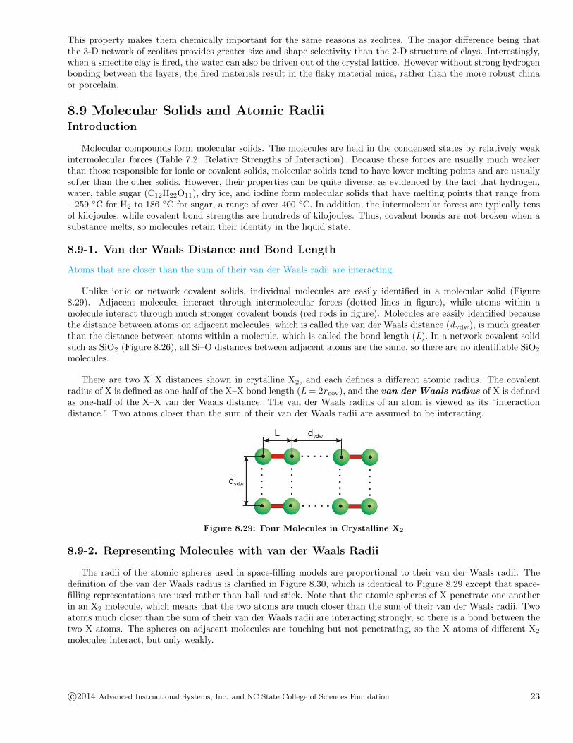
Unlike ionic or network covalent solids, individual molecules are easily identified in a molecular solid (Figure8.29). Adjacent molecules interact through intermolecular forces (dotted lines in figure), while atoms within amolecule interact through much stronger covalent bonds (red rods in figure). Molecules are easily identified becausethe distance between atoms on adjacent molecules, which is called the van der Waals distance (dvdw), is much greaterthan the distance between atoms within a molecule, which is called the bond length (L). In a network covalent solidsuch as SiO2 (Figure 8.26), all Si–O distances between adjacent atoms are the same, so there are no identifiable SiO2
molecules.
There are two X–X distances shown in crytalline X2, and each defines a different atomic radius. The covalentradius of X is defined as one-half of the X–X bond length (L = 2r cov), and the van der Waals radius of X is definedas one-half of the X–X van der Waals distance. The van der Waals radius of an atom is viewed as its “interactiondistance.” Two atoms closer than the sum of their van der Waals radii are assumed to be interacting.
Figure 8.29: Four Molecules in Crystalline X2
8.9-2. Representing Molecules with van der Waals Radii
The radii of the atomic spheres used in space-filling models are proportional to their van der Waals radii. Thedefinition of the van der Waals radius is clarified in Figure 8.30, which is identical to Figure 8.29 except that space-filling representations are used rather than ball-and-stick. Note that the atomic spheres of X penetrate one anotherin an X2 molecule, which means that the two atoms are much closer than the sum of their van der Waals radii. Twoatoms much closer than the sum of their van der Waals radii are interacting strongly, so there is a bond between thetwo X atoms. The spheres on adjacent molecules are touching but not penetrating, so the X atoms of different X2
molecules interact, but only weakly.
c©2014 Advanced Instructional Systems, Inc. and NC State College of Sciences Foundation 23
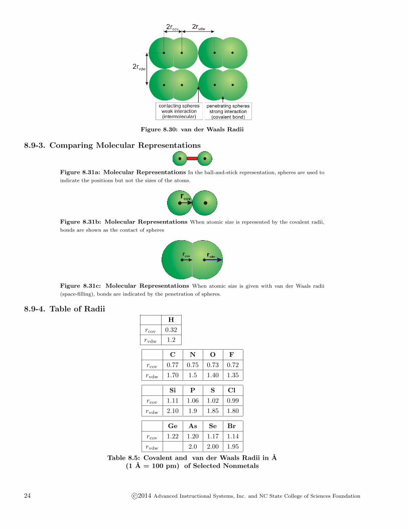
Figure 8.30: van der Waals Radii
8.9-3. Comparing Molecular Representations
Figure 8.31a: Molecular Representations In the ball-and-stick representation, spheres are used to
indicate the positions but not the sizes of the atoms.
Figure 8.31b: Molecular Representations When atomic size is represented by the covalent radii,
bonds are shown as the contact of spheres
Figure 8.31c: Molecular Representations When atomic size is given with van der Waals radii
(space-filling), bonds are indicated by the penetration of spheres.
8.9-4. Table of Radii
H
rcov 0.32
rvdw 1.2
C N O F
rcov 0.77 0.75 0.73 0.72
rvdw 1.70 1.5 1.40 1.35
Si P S Cl
rcov 1.11 1.06 1.02 0.99
rvdw 2.10 1.9 1.85 1.80
Ge As Se Br
rcov 1.22 1.20 1.17 1.14
rvdw 2.0 2.00 1.95
Table 8.5: Covalent and van der Waals Radii in A(1 A = 100 pm) of Selected Nonmetals
24 c©2014 Advanced Instructional Systems, Inc. and NC State College of Sciences Foundation
8.9-5. Radii Exercise
EXERCISE 8.7:What is the van der Waals distance in graphite as shown in Figure 8.21?dvdw = A
What is the van der Waals radius of carbon as determined from this distance?rvdw = A
8.9-6. Bond Length Exercise
EXERCISE 8.8:
Use the covalent radii in Table 8.5 to determine the Ge–Cl bond length.
r = A
8.10 Comparison of Solid TypesIntroductionObjectives• Determine the relative melting points of two substances based on the type of solid they form.
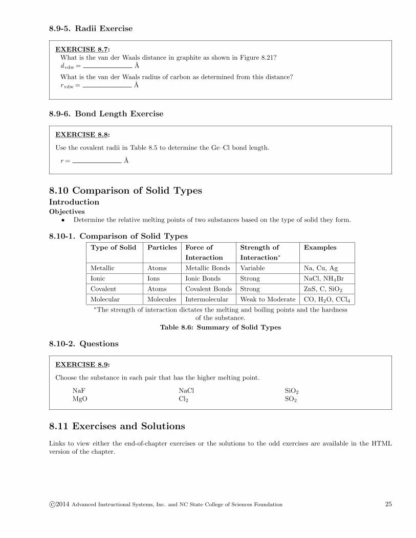
8.10-1. Comparison of Solid Types
Type of Solid Particles Force of Strength of Examples
Interaction Interaction∗
Metallic Atoms Metallic Bonds Variable Na, Cu, Ag
Ionic Ions Ionic Bonds Strong NaCl, NH4Br
Covalent Atoms Covalent Bonds Strong ZnS, C, SiO2
Molecular Molecules Intermolecular Weak to Moderate CO, H2O, CCl4∗The strength of interaction dictates the melting and boiling points and the hardness
of the substance.
Table 8.6: Summary of Solid Types
8.10-2. Questions
EXERCISE 8.9:
Choose the substance in each pair that has the higher melting point.
NaFMgO
NaClCl2
SiO2
SO2
8.11 Exercises and Solutions
Links to view either the end-of-chapter exercises or the solutions to the odd exercises are available in the HTMLversion of the chapter.
c©2014 Advanced Instructional Systems, Inc. and NC State College of Sciences Foundation 25