chapter 8: standby power systems - kazus.rukazus.ru/nuke/ebookss/230/chap08.pdf · most choose to...
TRANSCRIPT

Whitaker, Jerry C. “Standby Power Systems”AC Power Systems Handbook, 2nd Edition.Jerry C. WhitakerBoca Raton: CRC Press LLC, 1999

© 1999 CRC Press LLC
Chapter
8Standby Power Systems
8.1 Introduction
When utility company power problems are discussed, most people immediatelythink of blackouts. The lights go out, and everything stops. With the facility downand in the dark, there is nothing to do but sit and wait until the utility company findsthe problem and corrects it. This process generally takes only a few minutes. Thereare times, however, when it can take hours. In some remote locations, it can eventake days.
Blackouts are, without a doubt, the most troublesome utility company problemthat a facility will have to deal with. Statistics show that power failures are, gener-ally speaking, a rare occurrence in most areas of the country. They are also short induration. Studies have shown that 50 percent of blackouts last 6 s or less, and 35percent are less than 11 min long. These failure rates usually are not cause for con-cern to commercial users, except where computer-based operations, transportationcontrol systems, medical facilities, and communications sites are concerned.
When continuity of operation is critical, redundancy must be carried throughoutthe system. The site never should depend upon one critical path for ac power. Forexample, if the facility is fed by a single step-down transformer, a lightning flash orother catastrophic event could result in a transformer failure that would bring downthe entire site. A replacement could take days or even weeks.
8.1.1 Blackout Effects
A facility that is down for even 5 min can suffer a significant loss of productivity ordata that may take hours or days to rebuild. A blackout affecting a transportation ormedical center could be life-threatening. Coupled with this threat is the possibilityof extended power-service loss due to severe storm conditions. Many broadcast and
© 1999 CRC Press LLC
communications relay sites are located in remote, rural areas or on mountaintops.Neither of these kinds of locations are well-known for their power reliability. It isnot uncommon in mountainous areas for utility company service to be out forextended periods after a major storm. Few operators are willing to take such riskswith their business. Most choose to install standby power systems at appropriatepoints in the equipment chain.
The cost of standby power for a facility can be substantial, and an examination ofthe possible alternatives should be conducted before any decision on equipment ismade. Management must clearly define the direct and indirect costs and weigh themappropriately. Include the following items in the cost-vs.-risk analysis:
• Standby power-system equipment purchase and installation cost.
• Exposure of the system to utility company power failure.
• Alternative operating methods available to the facility.
• Direct and indirect costs of lost uptime because of blackout conditions.
A distinction must be made between emergency and standby power sources.Strictly speaking, emergency systems supply circuits legally designated as beingessential for safety to life and property. Standby power systems are used to protect afacility against the loss of productivity resulting from a utility company power out-age.
8.2 Standby Power Options
To ensure the continuity of ac power, many commercial/industrial facilities dependupon either two separate utility services or one utility service plus on-site genera-tion. Because of the growing complexity of electrical systems, attention must begiven to power-supply reliability.
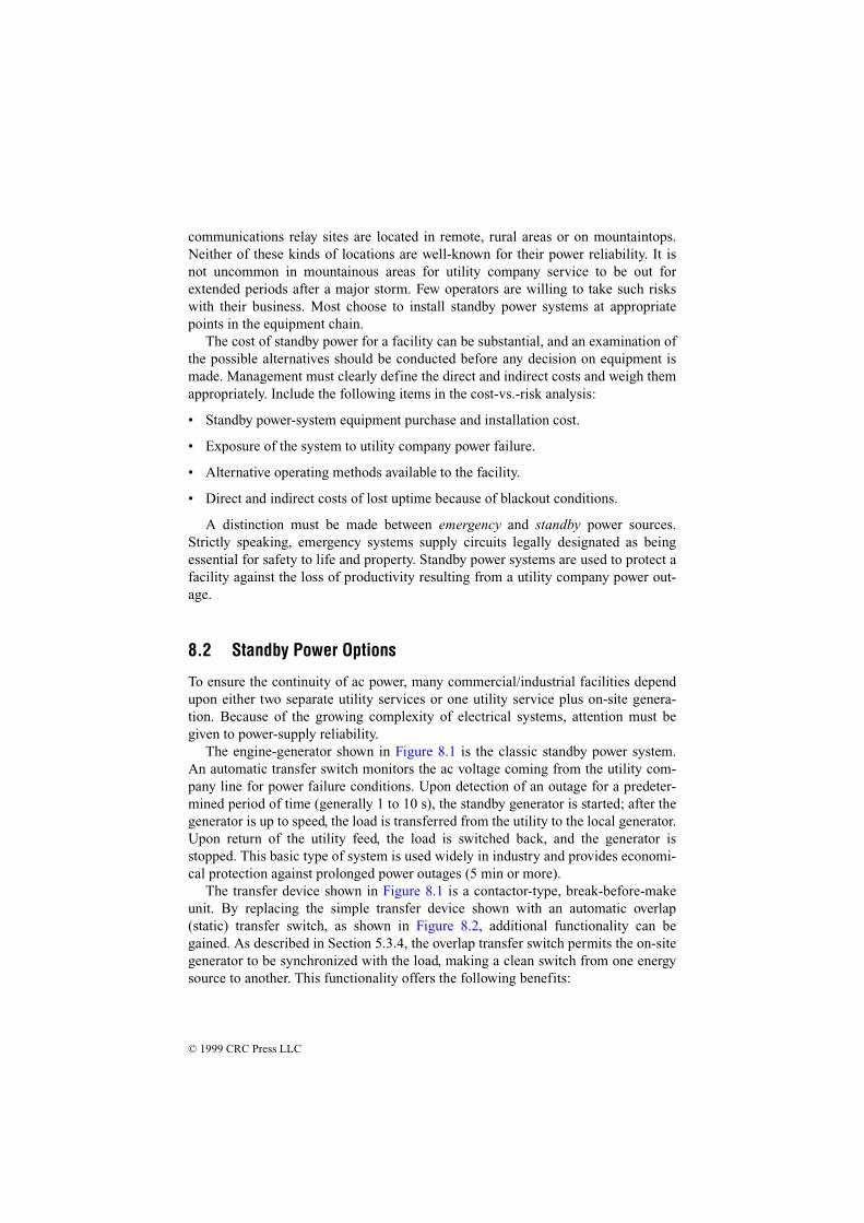
The engine-generator shown in Figure 8.1 is the classic standby power system.An automatic transfer switch monitors the ac voltage coming from the utility com-pany line for power failure conditions. Upon detection of an outage for a predeter-mined period of time (generally 1 to 10 s), the standby generator is started; after thegenerator is up to speed, the load is transferred from the utility to the local generator.Upon return of the utility feed, the load is switched back, and the generator isstopped. This basic type of system is used widely in industry and provides economi-cal protection against prolonged power outages (5 min or more).
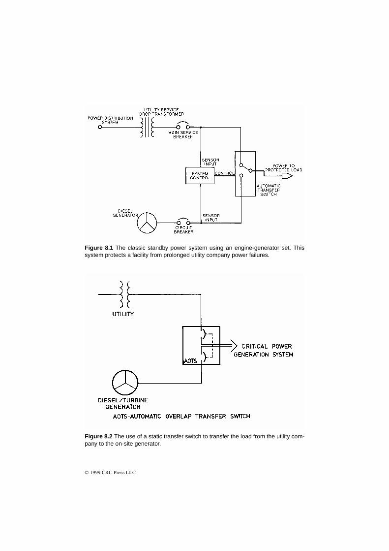
The transfer device shown in Figure 8.1 is a contactor-type, break-before-makeunit. By replacing the simple transfer device shown with an automatic overlap(static) transfer switch, as shown in Figure 8.2, additional functionality can begained. As described in Section 5.3.4, the overlap transfer switch permits the on-sitegenerator to be synchronized with the load, making a clean switch from one energysource to another. This functionality offers the following benefits:
© 1999 CRC Press LLC
Figure 8.1 The classic standby power system using an engine-generator set. Thissystem protects a facility from prolonged utility company power failures.
Figure 8.2 The use of a static transfer switch to transfer the load from the utility com-pany to the on-site generator.
© 1999 CRC Press LLC
• Switching back to the utility feed from the generator can be accomplished with-out interruption in service.
• The load can be cleanly switched from the utility to the generator in anticipationof utility line problems (such as an approaching severe storm).
• The load can be switched to and from the generator to accomplish load sheddingobjectives (discussed later in this chapter).
Dual Feeder System
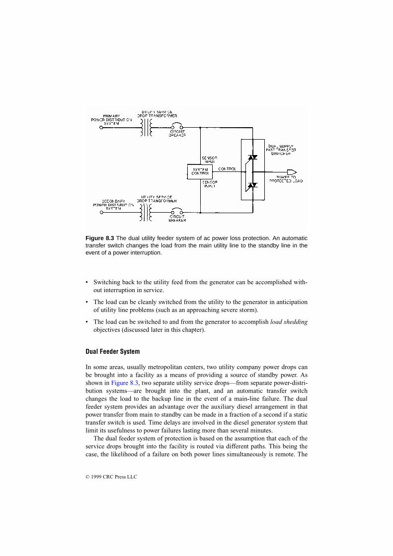
In some areas, usually metropolitan centers, two utility company power drops canbe brought into a facility as a means of providing a source of standby power. Asshown in Figure 8.3, two separate utility service drops—from separate power-distri-bution systems—are brought into the plant, and an automatic transfer switchchanges the load to the backup line in the event of a main-line failure. The dualfeeder system provides an advantage over the auxiliary diesel arrangement in thatpower transfer from main to standby can be made in a fraction of a second if a statictransfer switch is used. Time delays are involved in the diesel generator system thatlimit its usefulness to power failures lasting more than several minutes.
The dual feeder system of protection is based on the assumption that each of theservice drops brought into the facility is routed via different paths. This being thecase, the likelihood of a failure on both power lines simultaneously is remote. The
Figure 8.3 The dual utility feeder system of ac power loss protection. An automatictransfer switch changes the load from the main utility line to the standby line in theevent of a power interruption.

© 1999 CRC Press LLC
dual feeder system will not, however, protect against area-wide power failures,which can occur from time to time.
The dual feeder system is limited primarily to urban areas. Rural or mountainousregions generally are not equipped for dual redundant utility company operation.Even in urban areas, the cost of bringing a second power line into a facility can behigh, particularly if special lines must be installed for the feed. If two separate utilityservices are available at or near the site, redundant feeds generally will be lessexpensive than engine-driven generators of equivalent capacity.
Figure 8.4 illustrates a dual feeder system that utilizes both utility inputs simulta-neously at the facility. Notice that during normal operation, both ac lines feed loads,and the “tie” circuit breaker is open. In the event of a loss of either line, the circuit-breaker switches reconfigure the load to place the entire facility on the singleremaining ac feed. Switching is performed automatically; manual control is pro-vided in the event of a planned shutdown on one of the lines.
Figure 8.4 A dual utility feeder system with interlocked circuit breakers.
© 1999 CRC Press LLC
8.2.1 Peak Power Shaving
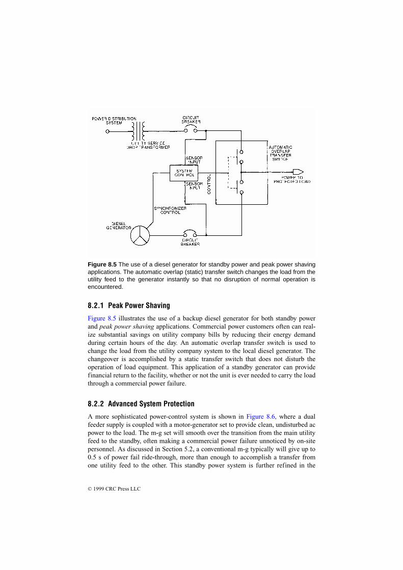
Figure 8.5 illustrates the use of a backup diesel generator for both standby powerand peak power shaving applications. Commercial power customers often can real-ize substantial savings on utility company bills by reducing their energy demandduring certain hours of the day. An automatic overlap transfer switch is used tochange the load from the utility company system to the local diesel generator. Thechangeover is accomplished by a static transfer switch that does not disturb theoperation of load equipment. This application of a standby generator can providefinancial return to the facility, whether or not the unit is ever needed to carry the loadthrough a commercial power failure.
8.2.2 Advanced System Protection
A more sophisticated power-control system is shown in Figure 8.6, where a dualfeeder supply is coupled with a motor-generator set to provide clean, undisturbed acpower to the load. The m-g set will smooth over the transition from the main utilityfeed to the standby, often making a commercial power failure unnoticed by on-sitepersonnel. As discussed in Section 5.2, a conventional m-g typically will give up to0.5 s of power fail ride-through, more than enough to accomplish a transfer fromone utility feed to the other. This standby power system is further refined in the
Figure 8.5 The use of a diesel generator for standby power and peak power shavingapplications. The automatic overlap (static) transfer switch changes the load from theutility feed to the generator instantly so that no disruption of normal operation isencountered.

© 1999 CRC Press LLC
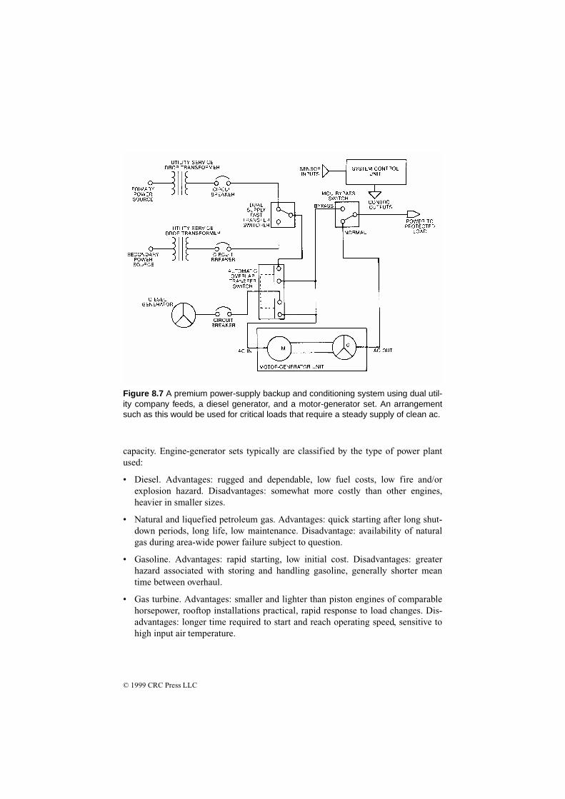
application illustrated in Figure 8.7, where a diesel generator has been added to thesystem. With the automatic overlap transfer switch shown at the generator output,this arrangement also can be used for peak demand power shaving.
Figure 8.8 shows a simplified schematic diagram of a 220 kW UPS system utiliz-ing dual utility company feed lines, a 750 kVA gas-engine generator, and five dc-driven motor-generator sets with a 20-min battery supply at full load. The five m-gsets operate in parallel. Each is rated for 100 kW output. Only three are needed topower the load, but four are on-line at any given time. The fifth machine providesredundancy in the event of a failure or for scheduled maintenance work. The batter-ies are always on-line under a slight charge across the 270 V dc bus. Two separatenatural-gas lines, buried along different land routes, supply the gas engine. Localgas storage capacity also is provided.
8.2.3 Choosing a Generator
Engine-generator sets are available for power levels ranging from less than 1 kVA toseveral thousand kVA or more. Machines also can be paralleled to provide greater
Figure 8.6 A dual feeder standby power system using a motor-generator set to pro-vide power fail ride-through and transient-disturbance protection. Switching circuitsallow the m-g set to be bypassed, if necessary.
© 1999 CRC Press LLC
capacity. Engine-generator sets typically are classified by the type of power plantused:
• Diesel. Advantages: rugged and dependable, low fuel costs, low fire and/orexplosion hazard. Disadvantages: somewhat more costly than other engines,heavier in smaller sizes.
• Natural and liquefied petroleum gas. Advantages: quick starting after long shut-down periods, long life, low maintenance. Disadvantage: availability of naturalgas during area-wide power failure subject to question.
• Gasoline. Advantages: rapid starting, low initial cost. Disadvantages: greaterhazard associated with storing and handling gasoline, generally shorter meantime between overhaul.
• Gas turbine. Advantages: smaller and lighter than piston engines of comparablehorsepower, rooftop installations practical, rapid response to load changes. Dis-advantages: longer time required to start and reach operating speed, sensitive tohigh input air temperature.
Figure 8.7 A premium power-supply backup and conditioning system using dual util-ity company feeds, a diesel generator, and a motor-generator set. An arrangementsuch as this would be used for critical loads that require a steady supply of clean ac.

© 1999 CRC Press LLC
The type of power plant chosen usually is determined primarily by the environmentin which the system will be operated and by the cost of ownership. For example, astandby generator located in an urban area office complex may be best suited to theuse of an engine powered by natural gas, because of the problems inherent in storinglarge amounts of fuel. State or local building codes can place expensive restrictionson fuel-storage tanks and make the use of a gasoline- or diesel-powered engine
Figure 8.8 Simplified installation diagram of a high-reliability power system incorpo-rating dual utility feeds, a standby gas-engine generator, and five battery-backed dcm-g sets. (After [1].)

© 1999 CRC Press LLC
impractical. The use of propane usually is restricted to rural areas. The availabilityof propane during periods of bad weather (when most power failures occur) alsomust be considered.
The generator rating for a standby power system should be chosen carefully andshould take into consideration the anticipated future growth of the plant. It is goodpractice to install a standby power system rated for at least 25 percent greater outputthan the current peak facility load. This headroom gives a margin of safety for thestandby equipment and allows for future expansion of the facility without overload-ing the system.
An engine-driven standby generator typically incorporates automatic startingcontrols, a battery charger, and automatic transfer switch. (See Figure 8.9.) Controlcircuits monitor the utility supply and start the engine when there is a failure or asustained voltage drop on the ac supply. The switch transfers the load as soon as thegenerator reaches operating voltage and frequency. Upon restoration of the utilitysupply, the switch returns the load and initiates engine shutdown. The automatictransfer switch must meet demanding requirements, including:
• Carrying the full rated current continuously
• Withstanding fault currents without contact separation
• Handling high inrush currents
• Withstanding many interruptions at full load without damage
The nature of most power outages requires a sophisticated monitoring system forthe engine-generator set. Most power failures occur during periods of bad weather.Most standby generators are unattended. More often than not, the standby systemwill start, run, and shut down without any human intervention or supervision. Forreliable operation, the monitoring system must check the status of the machine con-tinually to ensure that all parameters are within normal limits. Time-delay periodsusually are provided by the controller that require an outage to last from 5 to 10 sbefore the generator is started and the load is transferred. This prevents false startsthat needlessly exercise the system. A time delay of 5 to 30 min usually is allowedbetween the restoration of utility power and return of the load. This delay permitsthe utility ac lines to stabilize before the load is reapplied.
The transfer of motor loads may require special consideration, depending uponthe size and type of motors used at a plant. If the residual voltage of the motor is outof phase with the power source to which the motor is being transferred, serious dam-age can result to the motor. Excessive current draw also may trip overcurrent protec-tive devices. Motors above 50 hp with relatively high load inertia in relation totorque requirements, such as flywheels and fans, may require special controls.Restart time delays are a common solution.
Automatic starting and synchronizing controls are used for multiple-engine-gen-erator installations. The output of two or three smaller units can be combined to feedthe load. This capability offers additional protection for the facility in the event of a

© 1999 CRC Press LLC
failure in any one machine. As the load at the facility increases, additional engine-generator systems can be installed on the standby power bus.
8.2.3.1 Generator Types
Generators for standby power applications can be induction or synchronousmachines. Most engine-generator systems in use today are of the synchronous typebecause of the versatility, reliability, and capability of operating independently thatthis approach provides [2]. Most modern synchronous generators are of the revolv-ing field alternator design. Essentially, this means that the armature windings areheld stationary and the field is rotated. Therefore, generated power can be takendirectly from the stationary armature windings. Revolving armature alternators areless popular because the generated output power must be derived via slip rings andbrushes.
The exact value of the ac voltage produced by a synchronous machine is con-trolled by varying the current in the dc field windings, while frequency is controlledby the speed of rotation. Power output is controlled by the torque applied to the gen-
Figure 8.9 Typical configuration of an engine-generator set. (From [2]. Used withpermission.)
© 1999 CRC Press LLC
erator shaft by the driving engine. In this manner, the synchronous generator offersprecise control over the power it can produce.
Practically all modern synchronous generators use a brushless exciter. Theexciter is a small ac generator on the main shaft; the ac voltage produced is rectifiedby a 3-phase rotating rectifier assembly also on the shaft. The dc voltage thusobtained is applied to the main generator field, which is also on the main shaft. Avoltage regulator is provided to control the exciter field current, and in this manner,the field voltage can be precisely controlled, resulting in a stable output voltage.
The frequency of the ac current produced is dependent on two factors: the num-ber of poles built into the machine, and the speed of rotation (rpm). Because the out-put frequency must normally be maintained within strict limits (60 Hz or 50 Hz),control of the generator speed is essential. This is accomplished by providing pre-cise rpm control of the prime mover, which is performed by a governor.
There are many types of governors; however, for auxiliary power applications,the isochronous governor is normally selected. The isochronous governor controlsthe speed of the engine so that it remains constant from no-load to full load, assuringa constant ac power output frequency from the generator. A modern system consistsof two primary components: an electronic speed control and an actuator that adjuststhe speed of the engine. The electronic speed control senses the speed of themachine and provides a feedback signal to the mechanical/hydraulic actuator, whichin turn positions the engine throttle or fuel control to maintain accurate engine rpm.
The National Electrical Code provides guidance for safe and proper installationof on-site engine-generator systems. Local codes may vary and must be reviewedduring early design stages
8.2.4 UPS Systems
An uninterruptible power system is an elegant solution to power outage concerns.The output of the UPS inverter can be a sine wave or pseudo sine wave. (See Sec-tion 5.3.2.) When shopping for a UPS system, consider the following:
• Power reserve capacity for future growth of the facility.
• Inverter current surge capability (if the system will be driving inductive loads,such as motors).
• Output voltage and frequency stability over time and with varying loads.
• Required battery supply voltage and current. Battery costs vary greatly, depend-ing upon the type of units needed.
• Type of UPS system (forward-transfer type or reverse-transfer type) required bythe particular application. Some sensitive loads may not tolerate even brief inter-ruptions of the ac power source.
© 1999 CRC Press LLC
• Inverter efficiency at typical load levels. Some inverters have good efficiency rat-ings when loaded at 90 percent of capacity, but poor efficiency when lightlyloaded.
• Size and environmental requirements of the UPS system. High-power UPSequipment requires a large amount of space for the inverter/control equipmentand batteries. Battery banks often require special ventilation and ambient temper-ature control.
8.2.5 Standby Power-System Noise
Noise produced by backup power systems can be a serious problem if not addressedproperly. Standby generators, motor-generator sets, and UPS systems produce noisethat can disturb building occupants and irritate neighbors and/or landlords.
The noise associated with electrical generation usually is related to the drivemechanism, most commonly an internal combustion engine. The amplitude of thenoise produced is directly related to the size of the engine-generator set. First con-sider whether noise reduction is a necessity. Many building owners have elected totolerate the noise produced by a standby power generator because its use is limitedto emergency situations. During a crisis, when the normal source of power isunavailable, most people will tolerate noise associated with a standby generator.
If the decision is made that building occupants can live with the noise of the gen-erator, care must be taken in scheduling the required testing and exercising of theunit. Whether testing occurs monthly or weekly, it should be done on a regularschedule.
If it has been determined that the noise should be controlled, or at least mini-mized, the easiest way to achieve this objective is to physically separate the machinefrom occupied areas. This may be easier said than done. Because engine noise ispredominantly low-frequency in character, walls and floor/ceiling construction usedto contain the noise must be massive. Lightweight construction, even though it mayinvolve several layers of resiliently mounted drywall, is ineffective in reducing low-frequency noise. Exhaust noise is a major component of engine noise but, fortu-nately, it is easier to control. When selecting an engine-generator set, select the high-est-quality exhaust muffler available. Such units often are identified as “hospital-grade” mufflers.
Engine-generator sets also produce significant vibration. The machine should bemounted securely to a slab-on-grade or an isolated basement floor, or it should beinstalled on vibration isolation mounts. Such mounts usually are specified by themanufacturer.
Because a UPS system or motor-generator set is a source of continuous power, itmust run continuously. Noise must be adequately controlled. Physical separation isthe easiest and most effective method of shielding occupied areas from noise. Enclo-sure of UPS equipment usually is required, but noise control is significantly easierthan for an engine-generator because of the lower noise levels involved. Neverthe-less, the low-frequency 120 Hz fundamental of a UPS system is difficult to contain

© 1999 CRC Press LLC
adequately; massive constructions may be necessary. Vibration control also isrequired for most UPS and m-g gear.
8.2.6 Batteries
Batteries are the lifeblood of most UPS systems. Important characteristics includethe following:
• Charge capacity—how long the battery will operate the UPS.
• Weight.
• Charging characteristics.
• Durability/ruggedness.
Additional features that add to the utility of the battery include:
• Built-in status/temperature/charge indicator and/or data output port.
• Built-in over-temperature/over-current protection with auto-reset capabilities.
• Environmental friendliness.
The last point deserves some attention. Many battery types must be recycled or dis-posed of through some prescribed means. Proper disposal of a battery at the end ofits useful life is, thus, an important consideration. Be sure to check the original pack-aging for disposal instructions. Failure to follow the proper procedures could haveserious consequences.
Research has brought about a number of different battery chemistries, each offer-ing distinct advantages. Today’s most common and promising rechargeable chemis-tries include the following:
• Nickel cadmium (NiCd)—used for portable radios, cellular phones, video cam-eras, laptop computers, and power tools. NiCds have good load characteristics,are economically priced, and are simple to use.
• Lithium ion (Li-Ion)—now commonly available and typically used for videocameras. This battery promises to replace some NiCds for high energy-densityapplications.
• Sealed lead acid (SLA)—used for uninterruptible power systems, video cameras,and other demanding applications where the energy-to-weight ratio is not criticaland low battery cost is desirable.
• Nickel metal hydride (NiMH)—used for cellular phones, video cameras, and lap-top computers where high energy is of importance and cost is secondary.
• Lithium polymer (Li-Polymer)—when commercially available, this battery willhave the highest energy density and lowest self-discharge of common batterytypes, but its load characteristics will likely only suit low current applications.
© 1999 CRC Press LLC
• Reusable alkaline—used for light duty applications. Because of its low self-dis-charge, this battery is suitable for portable entertainment devices and other non-critical appliances that are used occasionally.
No single battery offers all the answers; rather, each chemistry is based on a numberof compromises.
A battery, of course, is only as good as its charger. Common attributes for thecurrent generation of charging systems include quick-charge capability and auto-matic battery condition analysis and subsequent intelligent charging.
8.2.6.1 Terms
The following terms are commonly used to specify and characterize batteries:
• Energy density. The storage capacity of a battery measured in watt-hours perkilogram (Wh/kg).
• Cycle life. The typical number of charge-discharge cycles for a given batterybefore the capacity decreases from the nominal 100 percent to approximately 80percent, depending upon the application.
• Fast-charge time. The time required to fully charge an empty battery.
• Self-discharge. The discharge rate when the battery is not in use.
• Cell voltage. The output voltage of the basic battery element. The cell voltagemultiplied by the number of cells provides the battery terminal voltage
• Load current. The maximum recommended current the battery can provide.
• Current rate. The C-rate is a unit by which charge and discharge times arescaled. If discharged at 1C, a 100 Ah battery provides a current of 100 A; if dis-charged at 0.5C, the available current is 50 A.
• Exercise requirement. This parameter indicates the frequency that the batteryneeds to be exercised to achieve maximum service life.
8.2.6.2 Sealed Lead-Acid Battery
The lead-acid battery is a commonly used chemistry. The flooded version is found inautomobiles and large UPS battery banks. Most smaller, portable systems use thesealed version, also referred to as gelcell or SLA.
The lead-acid chemistry is commonly used when high power is required, weightis not critical, and cost must be kept low [3]. The typical current range of a medium-sized SLA device is 2 Ah to 50 Ah. Because of its minimal maintenance require-ments and predictable storage characteristics, the SLA has found wide acceptance inthe UPS industry, especially for point-of-application systems.
The SLA is not subject to memory. No harm is done by leaving the battery onfloat charge for a prolonged time. On the negative side, the SLA does not lend itselfwell to fast charging. Typical charge times are 8 to 16 hours. The SLA must always
© 1999 CRC Press LLC
be stored in a charged state because a discharged SLA will sulphate. If left dis-charged, a recharge may be difficult or even impossible.
Unlike the common NiCd, the SLA prefers a shallow discharge. A full dischargereduces the number of times the battery can be recharged, similar to a mechanicaldevice that wears down when placed under stress. In fact, each discharge-chargecycle reduces (slightly) the storage capacity of the battery. This wear-down charac-teristic also applies to other chemistries, including the NiMH.
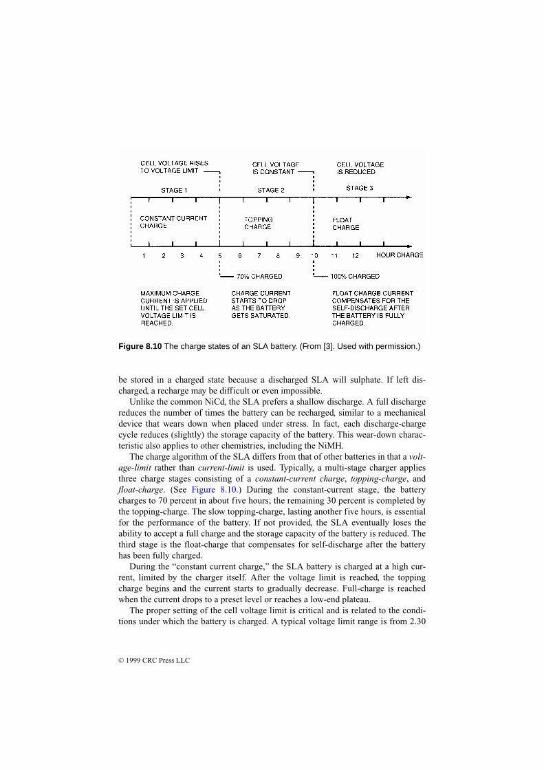
The charge algorithm of the SLA differs from that of other batteries in that a volt-age-limit rather than current-limit is used. Typically, a multi-stage charger appliesthree charge stages consisting of a constant-current charge, topping-charge, andfloat-charge. (See Figure 8.10.) During the constant-current stage, the batterycharges to 70 percent in about five hours; the remaining 30 percent is completed bythe topping-charge. The slow topping-charge, lasting another five hours, is essentialfor the performance of the battery. If not provided, the SLA eventually loses theability to accept a full charge and the storage capacity of the battery is reduced. Thethird stage is the float-charge that compensates for self-discharge after the batteryhas been fully charged.
During the “constant current charge,” the SLA battery is charged at a high cur-rent, limited by the charger itself. After the voltage limit is reached, the toppingcharge begins and the current starts to gradually decrease. Full-charge is reachedwhen the current drops to a preset level or reaches a low-end plateau.
The proper setting of the cell voltage limit is critical and is related to the condi-tions under which the battery is charged. A typical voltage limit range is from 2.30
Figure 8.10 The charge states of an SLA battery. (From [3]. Used with permission.)

© 1999 CRC Press LLC
V to 2.45 V. If a slow charge is acceptable, or if the room temperature can exceed30°C (86°F), the recommended voltage limit is 2.35 V/cell. If a faster charge isrequired and the room temperature remains below 30°C, 2.40 or 2.45 V/cell can beused. Table 8.1 compares the advantages and disadvantages of the different voltagesettings.
8.3 Fault Tolerance as a Design Objective
To achieve high levels of power system reliability—with the ultimate goal being 24-hour-per-day availability, 365 days per year—some form of power system redun-dancy is required, regardless of how reliable the individual power system compo-nents may be [4]. Redundancy, if properly implemented, also provides powerdistribution flexibility. By providing more than one path for power flow to the load,the key elements of a system can be shifted from one device or branch to another asrequired for load balancing, system renovations or alterations, or equipment failureisolation. Redundancy also provides a level of fault tolerance. Fault tolerance can bedivided into three basic categories:
• Rapid recovery from failures
• Protection against “slow” power system failures, where there is enough warningof the condition to allow intervention
• Protection against “fast” power system failures, where no warning of the powerfailure is given
As with many corrective and preventive measures, the increasing costs must beweighed against the benefits.
For example, recent developments in large UPS system technologies have pro-vided the capability to operate two independent UPS systems in parallel, either
Table 8.1 Recommended Charge Voltage Limit for the SLA Battery (After [3].)
2.30 V to 2.35 V/cell 2.40 V to 2.45 V/cell
Advantage Maximum service life; battery remains cool on charge; battery can be charged at ambient temperature exceeding 30°C (86°F).
Faster charge times; higher and more consistent capacity readings; less subject to damage because of under-charge condition.
Disadvan-tage
Slow charge time; capacity readings may be low and inconsistent. Produces under-charge condition that can cause sulphation and capacity loss if the bat-tery is not periodically cycled.
Battery life may be reduced because of elevated battery temperature while charging. A hot battery may fail to reach the cell voltage limit, causing harmful over-charge.

© 1999 CRC Press LLC
momentarily or continuously. The ability to momentarily connect two UPS systemsallows critical loads to be transferred from one UPS system to the other withoutplacing the UPS systems in bypass, thereby maintaining continuous UPS protectionof the loads. Continuous paralleling of the two UPS systems, on the other hand, canbe used to create a single redundant UPS system from two otherwise nonredundantsystems when multiple UPS modules are out of service (because of failures or main-tenance). Figure 8.11 illustrates one such implementation.
8.3.1 Critical System Bus
Many facilities do not require the operation of all equipment during a power outage.Rather than use one large standby power system, key pieces of equipment can beprotected with small, dedicated, uninterruptible power systems. Small UPS units areavailable with built-in battery supplies for computer systems and other hardware. Ifcost prohibits the installation of a system-wide standby power supply (using genera-tor or solid-state UPS technologies), consider establishing a critical load bus that isconnected to a UPS system or generator via an automatic transfer switch. This sepa-rate power supply is used to provide ac to critical loads, thus keeping the protectedsystems up and running. The concept is illustrated in Figure 8.12. Unnecessary loadsare dropped in the event of a power failure.
A standby system built on the critical load principle can be a cost-effectiveanswer to the power-failure threat. The first step in implementing a critical load busis to accurately determine the power requirements for the most important equip-ment. Typical power consumption figures can be found in most equipment instruc-tion manuals. If the data is not listed or available from the manufacturer, it can bemeasured using a wattmeter.
When planning a critical load bus, be certain to identify accurately which loadsare critical, and which can be dropped in the event of a commercial power failure. Ifair conditioning is interrupted but the computer equipment at a large data processingcenter continues to run, temperatures will rise quickly to the point at which systemcomponents may be damaged or the hardware automatically shuts down. It may notbe necessary to require cooling fans, chillers, and heat-exchange pumps to run with-out interruption. However, any outage should be less than 1 to 2 min in duration.Air-cooled computer systems can usually tolerate 5 to 10 min of cooling interrup-tion.
8.3.2 Power Distribution Options
There are essentially 12 building blocks that form what can be described as anassured, reliable, clean power source for computer systems, peripherals, and othercritical loads [5]. They are:
• Utility and service entry (step-down transformer, main disconnect, and panel-board, switchboard, or switchgear)

© 1999 CRC Press LLC
• Lightning protection
• Power bus
• Facility power distribution
• Grounding
Figure 8.11 Power distribution system featuring redundancy and high reliability. Ofparticular interest is the ability to parallel UPS systems as required by operationalconditions. (After [4].)

© 1999 CRC Press LLC
• Power conditioning equipment
• Critical load air-conditioning
• Frequency converter (if required)
Figure 8.12 An application of the critical-load power bus concept. In the event of apower failure, all equipment necessary for continued operation is powered by theUPS equipment. Noncritical loads are dropped until commercial ac returns.

© 1999 CRC Press LLC
• Batteries for dc backup power
• Emergency engine-generator
• Critical load power distribution network
• Emergency readiness planning
A power system to support a critical load cannot be said to be reliable unless allthese components are operating as intended, not only during normal operation, butespecially during an emergency.
It is easy to become complacent during periods when everything is functioningproperly, because this is the usual mode of operation. An absence of contingencyplans for dealing with an emergency situation, and a lack of understanding of howthe entire system works, thus, can lead to catastrophic shutdowns when an emer-gency situation arises. Proper training, and periodic reinforcing, is an essential com-ponent of a reliable system.
8.3.3 Plant Configuration
There are any number of hardware configurations that will provide redundancy andreliability for a critical load. Each situation is unique and requires an individualassessment of the options and—more importantly—the risks. The realities of eco-nomics dictate that cost is always a factor. Through proper design, however, theexpense usually can be held within an acceptable range.
Design for reliability begins at the utility service entrance [5]. The commonarrangement shown in Figure 8.13 is vulnerable to interruptions from faults at thetransformer and associated switching devices in the circuit. Furthermore, serviceentrance maintenance would require a plant shutdown. In Figure 8.14, redundancyhas been provided that will prevent the loss of power should one of the devices inthe line fail. Because the two transformers are located in separate physical enclo-sures, maintenance can be performed on one leg without dropping power to thefacility.
Of equal importance is the method of distributing power within a facility toachieve maximum reliability. This task is more difficult when dealing with a cam-pus-type facility or a process or manufacturing plant, where—instead of being con-centrated in a single room or floor—the critical loads may be in a number of distantlocations. Figure 8.15 illustrates power distribution through the facility using a sim-ple radial system. An incoming line supplies the main and line feeders via a serviceentrance transformer. This system is suitable for a single building or a small processplant. It is simple, reliable, and lowest in cost. However, such a system must be shutdown for routine maintenance, and it is vulnerable to single-point failure. Figure8.16 illustrates a distributed and redundant power distribution system that permitstransferring loads as required to patch around a fault condition. This configurationalso allows portions of the system to be de-energized for maintenance or upgradeswithout dropping the entire facility. Note the loop arrangement and associated

© 1999 CRC Press LLC
switches that permit optimum flexibility during normal and fault operating condi-tions.
Figure 8.14 Fault-tolerant serviceentrance system. (From [5]. Usedwith permission.)
Figure 8.13 Simplified serviceentrance system. (From [5]. Usedwith permission.)

© 1999 CRC Press LLC
8.4 The Efficient Use of Energy
Utility company power bills are usually a large part of the operating expenses of afacility. To reduce the amount of money spent each month on electricity, engineersmust understand the billing methods used by the utility. Saving energy is more com-plicated than simply turning off unnecessary lights. The amount of money that canbe saved through a well-planned energy conservation effort is often substantial.Reductions of 20 percent are not uncommon, depending upon the facility layout andthe extent of energy conservation efforts already under way. Regardless of any mon-etary savings that might be realized from a power-use-reduction program, the itemsdiscussed here should be considered for any well-run facility.
Figure 8.15 Secondary plant distri-bution using a simple radial configu-ration. (From [5]. Used withpermission.)

© 1999 CRC Press LLC
The rate structures of utility companies vary widely from one area of the countryto another. Some generalizations can be made, however, with respect to the basicrate-determining factors. The four primary parameters used to determine a cus-tomer's bill are:
• Energy usage
• Peak demand
• Load factor
• Power factor
These items often can be controlled, to some extent, by the customer.
8.4.1 Energy Usage
The kilowatthour (kWh) usage of a facility can be reduced by turning off loads suchas heating and air conditioning systems, lights, and office equipment when they arenot needed. The installation of timers, photocells, or sophisticated computer-con-trolled energy-management systems can make substantial reductions in facility kWhdemand each month. Common sense will dictate the conservation measures applica-ble to a particular situation. Obvious items include reducing the length of time high-power equipment is in operation, setting heating and cooling thermostats for reason-
Figure 8.16 A redundant, fault-tolerant secondary plant distribution system. (From[5]. Used with permission.)

© 1999 CRC Press LLC
able levels, keeping office equipment turned off during the night, and avoidingexcessive amounts of indoor or outdoor lighting.
Although energy conservation measures should be taken in every area of facilityoperation, the greatest savings generally can be found where the largest energy usersare located. Transmitter plants, large machinery, and process drying equipment con-sume a huge amount of power, so particular attention should be given to such hard-ware. Consider the following:
• Use the waste heat from equipment at the site for other purposes, if practical. Inthe case of high-power RF generators or transmitters, room heating can beaccomplished with a logic-controlled power amplifier exhaust-air recycling sys-tem.
• Have a knowledgeable consultant plan the air conditioning and heating system atthe facility for efficient operation.
• Check thermostat settings on a regular basis, and consider installing time-con-trolled thermostats.
• Inspect outdoor-lighting photocells regularly for proper operation.
• Examine carefully the efficiency of high-power equipment used at the facility.New designs may offer substantial savings in energy costs.
The efficiency of large power loads, such as mainframe computers, transmitters, orindustrial RF heaters, is an item of critical importance to energy conservationefforts. Most systems available today are significantly more efficient than theircounterparts of just 10 years ago. Plant management often can find economic justifi-cation for updating or replacing an older system on the power savings alone. In vir-tually any facility, energy conservation can best be accomplished through carefulselection of equipment, thoughtful system design, and conscientious maintenancepractices.
8.4.1.1 Peak Demand
Conserving energy is a big part of the power bill reduction equation, but it is not thewhole story. The peak demand of the customer load is an important criterion in theutility company's calculation of rate structures. The peak demand figure is a mea-sure of the maximum load placed on the utility company system by a customer dur-ing a predetermined billing cycle. The measured quantities may be kilowatts,kilovolt-amperes, or both. Time intervals used for this measurement range from 15to 60 min. Billing cycles may be annual or semiannual. Figure 8.17 shows an exam-ple of varying peak demand.
If a facility operated at basically the same power consumption level from onehour to the next and one day to the next, the utility company could predict accu-rately the demand of the load, and then size its equipment (including the allocationof energy reserves) for only the amount of power actually needed. For the exampleshown in the figure, however, the utility company must size its equipment (includ-

© 1999 CRC Press LLC
ing allocated energy reserves) for the peak demand. The area between the peakdemand and the actual usage is the margin of inefficiency that the customer forcesupon the utility. The peak demand factor is a method used by utility companies toassess penalties for such operation, thereby encouraging the customer to approach amore efficient state of operation (from the utility's viewpoint).
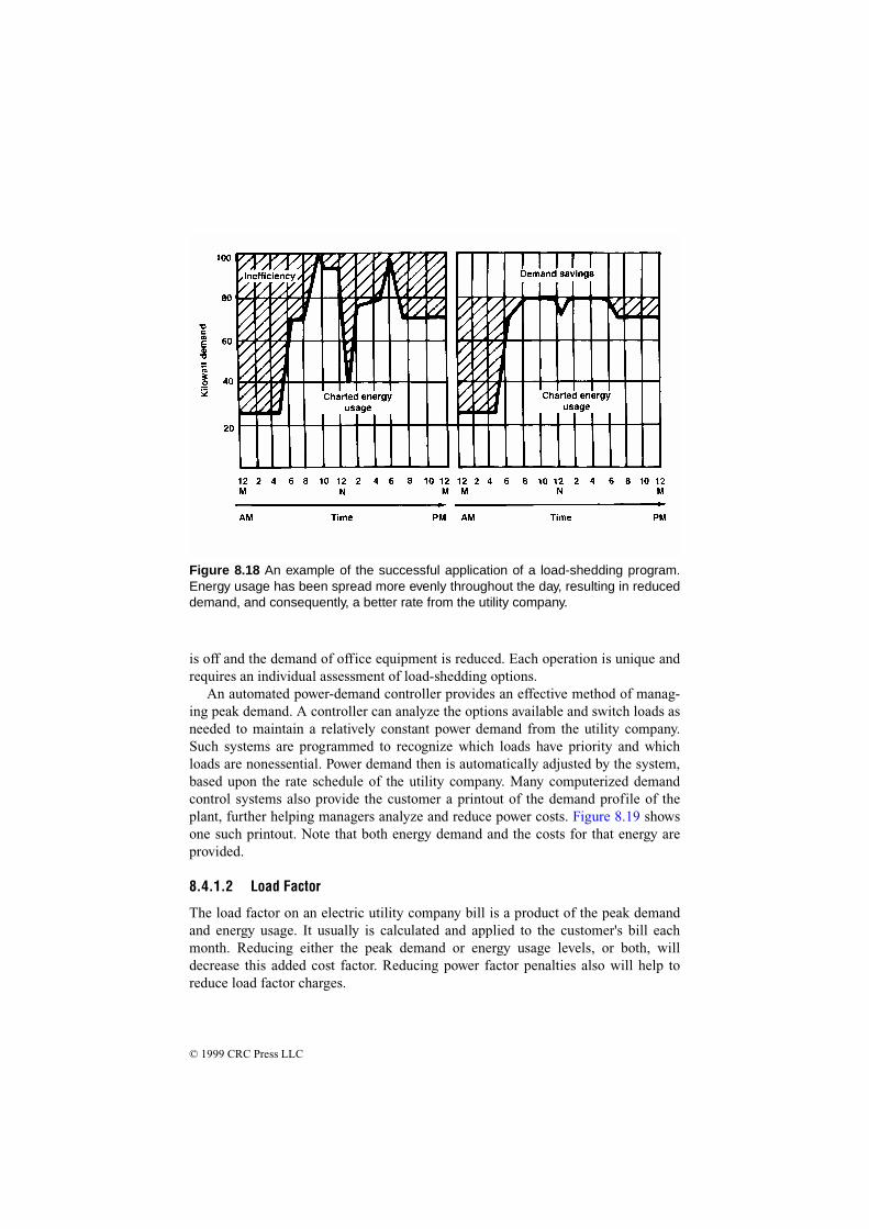
Load shedding is a term used to describe the practice of trimming peak powerdemand to reduce high-demand penalties. The goal of load shedding is to schedulethe operation of nonessential equipment so as to provide a uniform power load to theutility company, and thereby a better kWh rate. Nearly any operation has certainelectric loads that can be rescheduled on a permanent basis or deferred as powerdemand increases during the day. Figure 8.18 illustrates the results of a load-shed-ding program. This more efficient operation has a lower overall peak demand and ahigher average demand.
Peak demand reduction efforts can cover a wide range of possibilities. It wouldbe unwise from an energy standpoint, for example, to test high-power standbyequipment on a summer afternoon, when air conditioning units may be in full opera-tion. Morning or evening hours would be a better choice, when the air conditioning
Figure 8.17 The charted power consumption of a facility not practicing energy-man-agement techniques. Note the inefficiency that the utility company must absorb whenfaced with a load such as this.
© 1999 CRC Press LLC
is off and the demand of office equipment is reduced. Each operation is unique andrequires an individual assessment of load-shedding options.
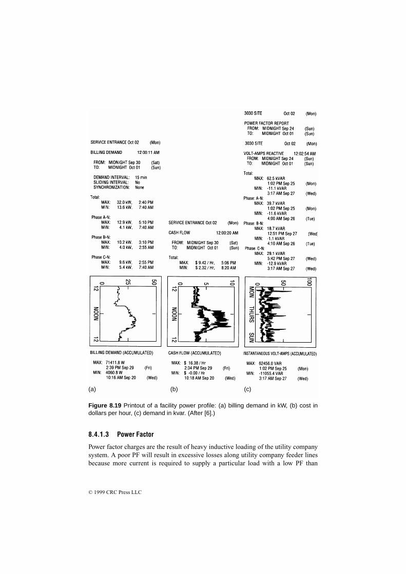
An automated power-demand controller provides an effective method of manag-ing peak demand. A controller can analyze the options available and switch loads asneeded to maintain a relatively constant power demand from the utility company.Such systems are programmed to recognize which loads have priority and whichloads are nonessential. Power demand then is automatically adjusted by the system,based upon the rate schedule of the utility company. Many computerized demandcontrol systems also provide the customer a printout of the demand profile of theplant, further helping managers analyze and reduce power costs. Figure 8.19 showsone such printout. Note that both energy demand and the costs for that energy areprovided.
8.4.1.2 Load Factor
The load factor on an electric utility company bill is a product of the peak demandand energy usage. It usually is calculated and applied to the customer's bill eachmonth. Reducing either the peak demand or energy usage levels, or both, willdecrease this added cost factor. Reducing power factor penalties also will help toreduce load factor charges.
Figure 8.18 An example of the successful application of a load-shedding program.Energy usage has been spread more evenly throughout the day, resulting in reduceddemand, and consequently, a better rate from the utility company.
© 1999 CRC Press LLC
8.4.1.3 Power Factor
Power factor charges are the result of heavy inductive loading of the utility companysystem. A poor PF will result in excessive losses along utility company feeder linesbecause more current is required to supply a particular load with a low PF than
(a) (b) (c)
Figure 8.19 Printout of a facility power profile: (a) billing demand in kW, (b) cost indollars per hour, (c) demand in kvar. (After [6].)
© 1999 CRC Press LLC
would be demanded if the load had a PF close to unity. (The technical aspects ofpower factor are discussed in Section 1.9.) The power factor charge is a penalty thatcustomers pay for the extra current needed to magnetize motors and other inductiveloads. This magnetizing current does not show up on the service drop wattmeter. Itis, instead, measured separately or prorated as an additional charge to the customer.The power factor penalty sometimes can be reduced through the addition of on-sitePF correction capacitors.
Power factor meters are available for measurement of a given load. It is usuallyless expensive in the long run, however, to hire a local electrical contractor to con-duct a PF survey and recommend correction methods. Possible sources of PF prob-lems include transmitters, blowers, air conditioners, heating equipment, andfluorescent and high-intensity discharge lighting-fixture ballasts.
In this section, we have only touched the surface of the power conservation issue.Interested readers are referred to [6] for a detailed discussion of energy-savingoptions and case histories.
8.5 Plant Maintenance
Maintenance of the facility electrical system is a key part of any serious energy-management effort. Perform the following steps on a regular basis:
• Measure the current drawn on distribution cables. Document the measurementsso that a history of power demand can be compiled.
• Check terminal and splice connections to make sure they are tight.
• Check power-system cables for excessive heating.
• Check cables for insulation problems.
• Clean switchboard and circuit-breaker panels.
• Measure the phase-to-phase load balance at the utility service entrance. Loadimbalance can result in inefficient use of ac power.
• Measure and chart the power factor of the load.
Develop and post a simplified one-line schematic of the entire power network aswell as other building systems, including heating, air conditioning, security, andalarm functions. A mimic board is helpful in this process. Construct the mimic boardcontrol panel so that it depicts the entire ac power-distribution system. The boardshould have active indicators that show what loads or circuit breakers are turned onor off, what functions have been disabled, and key operating parameters, includinginput voltage, load current, and total kVA demand. Safety considerations requirethat machinery not be activated from the mimic board. Permit machinery to be ener-gized only at the apparatus. As an alternative, remote control of machines can beprovided, if a remote/local control switch is provided at the apparatus.

© 1999 CRC Press LLC
Environmental control systems should be monitored closely. Air conditioning,heating, and ventilation systems often represent a significant portion of the powerload of a facility. Computer-based data-logging equipment with process controlcapability can be of considerable help in monitoring the condition of the equipment.The logger can be programmed to record all pertinent values periodically, and toreport abnormal conditions.
8.5.1 Switchgear Maintenance
All too often, ac power switchgear is installed at a facility and forgotten—until aproblem occurs. A careless approach to regular inspection and cleaning of switch-gear has resulted in numerous failures, including destructive fires. The most seriousfault in any switchgear assembly is arcing involving the main power bus. Protectivedevices often fail to open, or open only after a considerable delay. The arcing dam-age to busbars and enclosures can be significant. Fire often ensues, compoundingthe damage.
Moisture, combined with dust and dirt, is the greatest deteriorating factor insofaras insulation is concerned. Dust and/or moisture are thought to account for as muchas half of switchgear failures. Initial leakage paths across the surface of bus supportsresult in flashover and sustained arcing. Contact overheating is another commoncause of switchgear failure. Improper circuit-breaker installation or loose connec-tions can result in localized overheating and arcing.
An arcing fault is destructive because of the high temperatures present (morethan 6000°F). An arc is not a stationary event. Because of the ionization of gasesand the presence of vaporized metal, an arc can travel along bare busbars, spreadingthe damage and sometimes bypassing open circuit breakers. It has been observedthat most faults in three-phase systems involve all phases. The initial fault that trig-gers the event may involve only one phase, but because of the traveling nature of anarc, damage quickly spreads to the other lines.
Preventing switchgear failure is a complicated discipline, but consider the fol-lowing general guidelines:
• Install insulated busbars for both medium-voltage and low-voltage switchgear.Each phase of the bus and all connections should be enclosed completely byinsulation with electrical, mechanical, thermal, and flame-retardant characteris-tics suitable for the application.
• Establish a comprehensive preventive maintenance program for the facility. Keepall switchboard hardware clean from dust and dirt. Periodically check connectionpoints for physical integrity.
• Maintain control over environmental conditions. Switchgear exposed to contami-nants, corrosive gases, moist air, or high ambient temperatures may be subject tocatastrophic failure. Conditions favorable to moisture condensation are particu-larly perilous, especially when dust and dirt are present.

© 1999 CRC Press LLC
• Accurately select overcurrent trip settings, and check them on a regular basis.Adjust the trip points of protection devices to be as low as possible, consistentwith reliable operation.
• Divide switchgear into compartments that isolate different circuit elements. Con-sider adding vertical barriers to bus compartments to prevent the spread of arcingand fire.
• Install ground-fault protection devices at appropriate points in the power-distri-bution system
• Adhere to all applicable building codes.
8.5.2 Ground-System Maintenance
Out of sight, out of mind does not—or, at least, should not—apply to a facilityground system. Grounding is a crucial element in achieving reliable operation ofelectronic equipment. If a ground system has been buried for 10 years or more, it isdue for a complete inspection. If the system has been in place longer than 15 years,it is probably due for replacement. Soil conditions vary widely across the country,but few areas have soil that permits a ground system to last more than 15 years.
The method of construction and bonding of the ground network also can play asignificant role in the ultimate life expectancy of the system. For example, groundconductors secured only by mechanical means (screws and bolts, crimping, and riv-ets) can quickly break down when exposed to even mild soil conditions. Unless sil-ver-soldered or bonded using an exothermic method, such connections soon will beuseless for all practical purposes.
The inspection process involves uncovering portions of the ground system tocheck for evidence of failure. Pay particular attention to interconnection points,where the greatest potential for problems exists. In some cases, a good metal detec-tor will help identify portions of the ground system. It will not, however, identifybreaks in the system. Portions of the ground system still will need to be uncoveredto complete the inspection. Accurate documentation of the placement of ground-sys-tem components will aid the inspection effort greatly.
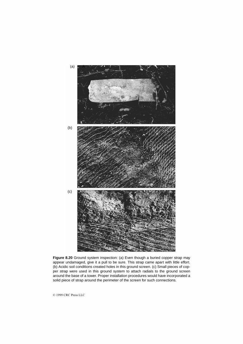
Check any buried mechanical connections carefully. Bolts that have been buriedfor many years may be severely deteriorated. Carefully remove several bolts, andinspect their condition. If a bolt is severely oxidized, it may twist off as it isremoved. After uncovering representative portions of the ground system, documentthe condition of the ground through notes and photographs. These will serve as areference point for future observation. The photos in Figure 8.20 illustrate some ofthe problems that can occur with an aging ground system. Note that many of theproblems experienced with the system shown in the photographs resulted fromimproper installation of components in the first place.
© 1999 CRC Press LLC
(b)
(c)
(a)
Figure 8.20 Ground system inspection: (a) Even though a buried copper strap mayappear undamaged, give it a pull to be sure. This strap came apart with little effort.(b) Acidic soil conditions created holes in this ground screen. (c) Small pieces of cop-per strap were used in this ground system to attach radials to the ground screenaround the base of a tower. Proper installation procedures would have incorporated asolid piece of strap around the perimeter of the screen for such connections.
A

© 1999 CRC Press LLC
8.6 References
1. Lawrie, Robert, Electrical Systems for Computer Installations, McGraw-Hill,New York, 1988.
2. DeDad, John A., “Auxiliary Power,” in Practical Guide to Power Distributionfor Information Technology Equipment, PRIMEDIA Intertec, Overland Park,KS, pp. 31–39, 1997.
3. Buchmann, Isidor, “Batteries,” in The Electronics Handbook, Jerry C. Whitaker(ed.), pg. 1058, CRC Press, Boca Raton, FL, 1996.
4. Gruzs, Thomas M., “High Availability, Fault-Tolerant AC Power DistributionSystems for Critical Loads, Proceedings, Power Quality Solutions/AlternativeEnergy, Intertec International, Ventura, CA, pp. 20–22, September, 1996.
5. DeDad, John A., “Considerations in Designing a Reliable Power DistributionSystem,” in Practical Guide to Power Distribution for Information TechnologyEquipment, PRIMEDIA Intertec, Overland Park, KS, pp. 4–8, 1997.
6. Lawrie, Robert H., Practical Guide to Electrical Energy Efficiency andReduced Costs, PRIMEDIA Intertec, Overland Park, KS, 1994.
8.7 Bibliography
Angevine, Eric, “Controlling Generator and UPS Noise,” Broadcast Engineering,PRIMEDIA Intertec, Overland Park, KS, March 1989.
Baietto, Ron, “How to Calculate the Proper Size of UPS Devices,” MicroserviceManagement, PRIMEDIA Intertec, Overland Park, KS, March 1989.
Federal Information Processing Standards Publication No. 94, Guideline on Electri-cal Power for ADP Installations, U.S. Department of Commerce, NationalBureau of Standards, Washington, D.C., 1983.
Highnote, Ronnie L., The IFM Handbook of Practical Energy Management, Insti-tute for Management, Old Saybrook, CT, 1979.
Smith, Morgan, “Planning for Standby AC Power,” Broadcast Engineering, PRI-MEDIA Intertec, Overland Park, KS, March 1989.
Stuart, Bud, “Maintaining an Antenna Ground System,” Broadcast Engineering,PRIMEDIA Intertec, Overland Park, KS, October 1986.