chapter 8 roof-ceiling construction - … 8 roof-ceiling construction section r801 ... the name of...
TRANSCRIPT

CHAPTER 8
ROOF-CEILING CONSTRUCTION
SECTION R801GENERAL
R801.1 Application. The provisions of this chapter shall con-trol the design and construction of the roof-ceiling system forall buildings.
R801.2 Requirements. Roof and ceiling construction shall becapable of accommodating all loads imposed according to Sec-tion R301 and of transmitting the resulting loads to the support-ing structural elements.
R801.3 Roof drainage. In areas where expansive or collaps-ible soils are known to exist, all dwellings shall have a con-trolled method of water disposal from roofs that will collectand discharge roof drainage to the ground surface at least 5 feet(1524 mm) from foundation walls or to an approved drainagesystem.
SECTION R802WOOD ROOF FRAMING
R802.1 Identification. Load-bearing dimension lumber forrafters, trusses and ceiling joists shall be identified by a grademark of a lumber grading or inspection agency that has beenapproved by an accreditation body that complies with DOC PS20. In lieu of a grade mark, a certificate of inspection issued bya lumber grading or inspection agency meeting the require-ments of this section shall be accepted.
R802.1.1 Blocking. Blocking shall be a minimum of utilitygrade lumber.
R802.1.2 End-jointed lumber. Approved end-jointed lum-ber identified by a grade mark conforming to SectionR802.1 may be used interchangeably with solid-sawn mem-bers of the same species and grade.
R802.1.3 Fire-retardant-treated wood. Fire-retardant-treated wood (FRTW) is any wood product which, whenimpregnated with chemicals by a pressure process or othermeans during manufacture, shall have, when tested inaccordance with ASTM E 84, a listed flame spread index of25 or less and shows no evidence of significant progressivecombustion when the test is continued for an additional20-minute period. In addition, the flame front shall notprogress more than 10.5 feet (3200 mm) beyond the centerline of the burners at any time during the test.
R802.1.3.1 Labeling. Fire-retardant-treated lumber andwood structural panels shall be labeled. The label shallcontain:
1. The identification mark of an approved agency inaccordance with Section 1703.5 of the Interna-tional Building Code.
2. Identification of the treating manufacturer.
3. The name of the fire-retardant treatment.
4. The species of wood treated.
5. Flame spread and smoke-developed rating.
6. Method of drying after treatment.
7. Conformance to appropriate standards in accor-dance with Sections R802.1.3.2 throughR802.1.3.5.
8. For FRTW exposed to weather, or a damp or wetlocation, the words “No increase in the listed clas-sification when subjected to the Standard RainTest” (ASTM D 2898).
R802.1.3.2 Strength adjustments. Design values foruntreated lumber and wood structural panels as specifiedin Section R802.1 shall be adjusted for fire-retardant-treated wood. Adjustments to design values shall bebased upon an approved method of investigation whichtakes into consideration the effects of the anticipatedtemperature and humidity to which the fire-retar-dant-treated wood will be subjected, the type of treat-ment and redrying procedures.
R802.1.3.2.1 Wood structural panels. The effect oftreatment and the method of redrying after treatment,and exposure to high temperatures and highhumidities on the flexure properties of fire-retar-dant-treated softwood plywood shall be determinedin accordance with ASTM D 5516. The test datadeveloped by ASTM D 5516 shall be used to developadjustment factors, maximum loads and spans, orboth for untreated plywood design values in accor-dance with ASTM D 6305. Each manufacturer shallpublish the allowable maximum loads and spans forservice as floor and roof sheathing for their treatment.
R802.1.3.2.2 Lumber. For each species of woodtreated, the effect of the treatment and the method ofredrying after treatment and exposure to high tempera-tures and high humidities on the allowable designproperties of fire-retardant-treated lumber shall bedetermined in accordance with ASTM D 5664. Thetest data developed by ASTM D 5664 shall be used todevelop modification factors for use at or near roomtemperature and at elevated temperatures and humidityin accordance with ASTM D 6841. Each manufacturershall publish the modification factors for service attemperatures of not less than 80°F (27°C) and for roofframing. The roof framing modification factors shalltake into consideration the climatological location.
R802.1.3.3 Exposure to weather. Where fire-retar-dant-treated wood is exposed to weather or damp or wetlocations, it shall be identified as “Exterior” to indicatethere is no increase in the listed flame spread index asdefined in Section R802.1.3 when subjected to ASTM D2898.
INTERNATIONAL RESIDENTIAL CODE 2006, NEW JERSEY EDITION 235
108_NJ_Res_2006.prnM:\data\CODES\STATE CODES\New Jersey\2006\NJ_Res_2006\Final VP_Chgo\08_NJ_Res_2006.vpTuesday, April 17, 2007 11:32:25 AM
Color profile: Generic CMYK printer profileComposite Default screen

R802.1.3.4 Interior applications. Interior fire-retar-dant-treated wood shall have a moisture content of notover 28 percent when tested in accordance with ASTM D3201 procedures at 92 percent relative humidity. Interiorfire-retardant-treated wood shall be tested in accordancewith Section R802.1.3.2.1 or R802.1.3.2.2. Interiorfire-retardant-treated wood designated as Type A shallbe tested in accordance with the provisions of this sec-tion.
R802.1.3.5 Moisture content. Fire-retardant-treatedwood shall be dried to a moisture content of 19 percent orless for lumber and 15 percent or less for wood structuralpanels before use. For wood kiln dried after treatment(KDAT) the kiln temperatures shall not exceed thoseused in kiln drying the lumber and plywood submittedfor the tests described in Section R802.1.3.2.1 for ply-wood and R802.1.3.2.2 for lumber.
R802.1.4 Structural glued laminated timbers. Gluedlaminated timbers shall be manufactured and identified asrequired in AITC A190.1 and ASTM D 3737.
R802.1.5 Structural log members. Stress grading of struc-tural log members of nonrectangular shape, as typicallyused in log buildings, shall be in accordance with ASTM D3957. Such structural log members shall be identified by thegrade mark of an approved lumber grading or inspectionagency. In lieu of a grade mark on the material, a certificateof inspection as to species and grade issued by a lum-ber-grading or inspection agency meeting the requirementsof this section shall be permitted to be accepted.
R802.2 Design and construction. The framing detailsrequired in Section R802 apply to roofs having a minimumslope of three units vertical in 12 units horizontal (25-percentslope) or greater. Roof-ceilings shall be designed and con-structed in accordance with the provisions of this chapter andFigures R606.11(1), R606.11(2) and R606.11(3) or in accor-dance with AFPA/NDS. Components of roof-ceilings shall befastened in accordance with Table R602.3(1).
R802.3 Framing details. Rafters shall be framed to ridgeboard or to each other with a gusset plate as a tie. Ridge boardshall be at least 1-inch (25 mm) nominal thickness and not lessin depth than the cut end of the rafter. At all valleys and hipsthere shall be a valley or hip rafter not less than 2-inch (51 mm)nominal thickness and not less in depth than the cut end of therafter. Hip and valley rafters shall be supported at the ridge by abrace to a bearing partition or be designed to carry and distrib-ute the specific load at that point. Where the roof pitch is lessthan three units vertical in 12 units horizontal (25-percentslope), structural members that support rafters and ceilingjoists, such as ridge beams, hips and valleys, shall be designedas beams.
R802.3.1 Ceiling joist and rafter connections. Ceilingjoists and rafters shall be nailed to each other in accordancewith Table R802.5.1(9), and the rafter shall be nailed to thetop wall plate in accordance with Table R602.3(1). Ceilingjoists shall be continuous or securely joined in accordancewith Table R802.5.1(9) where they meet over interior parti-tions and are nailed to adjacent rafters to provide a continu-
ous tie across the building when such joists are parallel tothe rafters.
Where ceiling joists are not connected to the rafters at thetop wall plate, joists connected higher in the attic shall beinstalled as rafter ties, or rafter ties shall be installed to pro-vide a continuous tie. Where ceiling joists are not parallel torafters, rafter ties shall be installed. Rafter ties shall be aminimum of 2-inch by 4-inch (51 mm by 102 mm) (nomi-nal), installed in accordance with the connection require-ments in Table R802.5.1(9), or connections of equivalentcapacities shall be provided. Where ceiling joists or rafterties are not provided, the ridge formed by these rafters shallbe supported by a wall or girder designed in accordancewith accepted engineering practice.
Collar ties or ridge straps to resist wind uplift shall beconnected in the upper third of the attic space in accordancewith Table R602.3(1).
Collar ties shall be a minimum of 1-inch by 4-inch (25mm by 102 mm) (nominal), spaced not more than 4 feet(1219 mm) on center.
R802.3.2 Ceiling joists lapped. Ends of ceiling joists shallbe lapped a minimum of 3 inches (76 mm) or butted overbearing partitions or beams and toenailed to the bearingmember. When ceiling joists are used to provide resistanceto rafter thrust, lapped joists shall be nailed together inaccordance with Table R602.3(1) and butted joists shall betied together in a manner to resist such thrust.
R802.4 Allowable ceiling joist spans. Spans for ceiling joistsshall be in accordance with Tables R802.4(1) and R802.4(2).For other grades and species and for other loading conditions,refer to the AF&PA Span Tables for Joists and Rafters.
R802.5 Allowable rafter spans. Spans for rafters shall be inaccordance with Tables R802.5.1(1) through R802.5.1(8). Forother grades and species and for other loading conditions, referto the AF&PA Span Tables for Joists and Rafters. The span ofeach rafter shall be measured along the horizontal projection ofthe rafter.
R802.5.1 Purlins. Installation of purlins to reduce the spanof rafters is permitted as shown in Figure R802.5.1. Purlinsshall be sized no less than the required size of the rafters thatthey support. Purlins shall be continuous and shall be sup-ported by 2-inch by 4-inch (51 mm by 102 mm) bracesinstalled to bearing walls at a slope not less than 45 degreesfrom the horizontal. The braces shall be spaced not morethan 4 feet (1219 mm) on center and the unbraced length ofbraces shall not exceed 8 feet (2438 mm).
R802.6 Bearing. The ends of each rafter or ceiling joist shallhave not less than 11/2 inches (38 mm) of bearing on wood ormetal and not less than 3 inches (76 mm) on masonry or con-crete.
R802.6.1 Finished ceiling material. If the finished ceilingmaterial is installed on the ceiling prior to the attachment ofthe ceiling to the walls, such as in construction at a factory, acompression strip of the same thickness as the finish ceilingmaterial shall be installed directly above the top plate ofbearing walls if the compressive strength of the finish ceil-ing material is less than the loads it will be required to with-
236 INTERNATIONAL RESIDENTIAL CODE 2006, NEW JERSEY EDITION
ROOF-CEILING CONSTRUCTION
208_NJ_Res_2006.prnM:\data\CODES\STATE CODES\New Jersey\2006\NJ_Res_2006\Final VP_Chgo\08_NJ_Res_2006.vpTuesday, April 17, 2007 11:32:25 AM
Color profile: Generic CMYK printer profileComposite Default screen

stand. The compression strip shall cover the entire length ofsuch top plate and shall be at least one-half the width of thetop plate. It shall be of material capable of transmitting theloads transferred through it.
R802.7 Cutting and notching. Structural roof members shallnot be cut, bored or notched in excess of the limitations speci-fied in this section.
R802.7.1 Sawn lumber. Notches in solid lumber joists, raf-ters and beams shall not exceed one-sixth of the depth of themember, shall not be longer than one-third of the depth ofthe member and shall not be located in the middle one-thirdof the span. Notches at the ends of the member shall notexceed one-fourth the depth of the member. The tensionside of members 4 inches (102 mm) or greater in nominalthickness shall not be notched except at the ends of themembers. The diameter of the holes bored or cut into mem-bers shall not exceed one-third the depth of the member.Holes shall not be closer than 2 inches (51 mm) to the top orbottom of the member, or to any other hole located in themember. Where the member is also notched, the hole shallnot be closer than 2 inches (51 mm) to the notch.
Exception: Notches on cantilevered portions of raftersare permitted provided the dimension of the remainingportion of the rafter is not less than 4-inch nominal (102mm) and the length of the cantilever does not exceed 24inches (610 mm).
R802.7.2 Engineered wood products. Cuts, notches andholes bored in trusses, structural composite lumber, struc-tural glue-laminated members or I-joists are prohibitedexcept where permitted by the manufacturer’s recommen-dations or where the effects of such alterations are specifi-cally considered in the design of the member by a registereddesign professional.
R802.8 Lateral support. Rafters and ceiling joists having adepth-to-thickness ratio exceeding 5 to 1 based on nominaldimensions shall be provided with lateral support at points ofbearing to prevent rotation.
R802.8.1 Bridging. Rafters and ceiling joists having a depth-to-thickness ratio exceeding 6 to 1 based on nominal dimen-sions shall be supported laterally by solid blocking, diagonalbridging (wood or metal) or a continuous 1-inch by 3-inch(25 mm by 76 mm) wood strip nailed across the rafters orceiling joists at intervals not exceeding 8 feet (2438 mm).
R802.9 Framing of openings. Openings in roof and ceilingframing shall be framed with header and trimmer joists. Whenthe header joist span does not exceed 4 feet (1219 mm), theheader joist may be a single member the same size as the ceilingjoist or rafter. Single trimmer joists may be used to carry a sin-gle header joist that is located within 3 feet (914 mm) of thetrimmer joist bearing. When the header joist span exceeds 4feet (1219 mm), the trimmer joists and the header joist shall bedoubled and of sufficient cross section to support the ceilingjoists or rafter framing into the header. Approved hangers shallbe used for the header joist to trimmer joist connections whenthe header joist span exceeds 6 feet (1829 mm). Tail joists over12 feet (3658 mm) long shall be supported at the header by
framing anchors or on ledger strips not less than 2 inches by 2inches (51 mm by 51 mm).
R802.10 Wood trusses.
R802.10.1 Truss design drawings. Truss design drawings,prepared in conformance to Section R802.10.1, shall beprovided to the building official and approved prior toinstallation. Truss design drawings shall include, at a mini-mum, the information specified below. Truss design draw-ing and truss layout drawings shall be provided with theshipment of trusses delivered to the jobsite.
1. Slope or depth, span and spacing.
2. Location of all joints.
3. Required bearing widths.
4. Design loads as applicable.
4.1. Top chord live load (as determined from Sec-tion R301.6).
4.2. Top chord dead load.
4.3. Bottom chord live load.
4.4. Bottom chord dead load.
4.5. Concentrated loads and their points of appli-cation.
4.6. Controlling wind and earthquake loads.
5. Adjustments to lumber and joint connector designvalues for conditions of use.
6. Each reaction force and direction.
7. Joint connector type and description (e.g., size,thickness or gage) and the dimensioned location ofeach joint connector except where symmetricallylocated relative to the joint interface.
8. Lumber size, species and grade for each member.
9. Connection requirements for:
9.1. Truss to girder-truss.
9.2. Truss ply to ply.
9.3. Field splices.
10. Calculated deflection ratio and/or maximumdescription for live and total load.
11. Maximum axial compression forces in the trussmembers to enable the building designer to designthe size, connections and anchorage of the perma-nent continuous lateral bracing. Forces shall beshown on the truss design drawing or on supplemen-tal documents.
12. Required permanent truss member bracing location.
R802.10.2 Design. Wood trusses shall be designed in accor-dance with accepted engineering practice. The design andmanufacture of metal-plate-connected wood trusses shallcomply with ANSI/TPI 1. The truss design drawings shallbe prepared by a registered professional where required bythe statutes of the jurisdiction in which the project is to beconstructed in accordance with Section R106.1.
INTERNATIONAL RESIDENTIAL CODE 2006, NEW JERSEY EDITION 237
ROOF-CEILING CONSTRUCTION
308_NJ_Res_2006.prnM:\data\CODES\STATE CODES\New Jersey\2006\NJ_Res_2006\Final VP_Chgo\08_NJ_Res_2006.vpTuesday, April 17, 2007 11:32:25 AM
Color profile: Generic CMYK printer profileComposite Default screen

238 INTERNATIONAL RESIDENTIAL CODE 2006, NEW JERSEY EDITION
ROOF-CEILING CONSTRUCTION
TABLE R802.4(1)CEILING JOIST SPANS FOR COMMON LUMBER SPECIES
(Uninhabitable attics without storage, live load = 10 psf, L/Δ = 240)
CEILING JOISTSPACING(inches) SPECIES AND GRADE
DEAD LOAD = 5 psf
2 × 4 2 × 6 2 × 8 2 × 10
Maximum ceiling joist spans
(feet - inches) (feet - inches) (feet - inches) (feet - inches)
12
Douglas fir-larch SSDouglas fir-larch #1Douglas fir-larch #2Douglas fir-larch #3Hem-fir SSHem-fir #1Hem-fir #2Hem-fir #3Southern pine SSSouthern pine #1Southern pine #2Southern pine #3Spruce-pine-fir SSSpruce-pine-fir #1Spruce-pine-fir #2Spruce-pine-fir #3
13-212-812-510-1012-512-211-710-1012-1112-812-511-612-211-1011-1010-10
20-819-1119-615-1019-619-118-215-1020-319-1119-617-019-118-818-815-10
Note aNote a25-820-125-825-224-020-1
Note aNote a25-821-825-224-724-720-1
Note aNote aNote a24-6
Note aNote aNote a24-6
Note aNote aNote a25-7
Note aNote aNote a24-6
16
Douglas fir-larch SSDouglas fir-larch #1Douglas fir-larch #2Douglas fir-larch #3Hem-fir SSHem-fir #1Hem-fir #2Hem-fir #3Southern pine SSSouthern pine #1Southern pine #2Southern pine #3Spruce-pine-fir SSSpruce-pine-fir #1Spruce-pine-fir #2Spruce-pine-fir #3
11-1111-611-39-511-311-010-69-511-911-611-310-011-010-910-99-5
18-918-117-813-917-817-416-613-918-518-117-814-917-416-1116-1113-9
24-823-1023-017-523-422-1021-917-524-323-123-418-922-1022-422-417-5
Note aNote aNote a21-3
Note aNote aNote a21-3
Note aNote aNote a22-2
Note aNote aNote a21-3
19.2
Douglas fir-larch SSDouglas fir-larch #1Douglas fir-larch #2Douglas fir-larch #3Hem-fir SSHem-fir #1Hem-fir #2Hem-fir #3Southern -pine SSSouthern pine #1Southern pine #2Southern pine #3Spruce-pine-fir SSSpruce-pine-fir #1Spruce-pine-fir #2Spruce-pine-fir #3
11-310-1010-78-710-710-49-118-711-010-1010-79-110-410-210-28-7
17-817-016-712-616-816-415-712-617-417-016-813-616-415-1115-1112-6
23-322-521-015-1021-1121-620-615-1022-1022-521-1117-221-621-021-015-10
Note aNote a25-819-5
Note aNote a25-319-5
Note aNote aNote a20-3
Note a25-825-819-5
(continued)
408_NJ_Res_2006.prnM:\data\CODES\STATE CODES\New Jersey\2006\NJ_Res_2006\Final VP_Chgo\08_NJ_Res_2006.vpTuesday, April 17, 2007 11:32:26 AM
Color profile: Generic CMYK printer profileComposite Default screen

INTERNATIONAL RESIDENTIAL CODE 2006, NEW JERSEY EDITION 239
ROOF-CEILING CONSTRUCTION
TABLE R802.4(1)—continuedCEILING JOIST SPANS FOR COMMON LUMBER SPECIES
(Uninhabitable attics without storage, live load = 10 psf, L/Δ = 240)
CEILING JOISTSPACING(inches) SPECIES AND GRADE
DEAD LOAD = 5 psf
2 × 4 2 × 6 2 × 8 2 × 10
Maximum ceiling joist spans
(feet - inches) (feet - inches) (feet - inches) (feet - inches)
24
Douglas fir-larch SSDouglas fir-larch #1Douglas fir-larch #2Douglas fir-larch #3Hem-fir SSHem-fir #1Hem-fir #2Hem-fir #3Southern pine SSSouthern pine #1Southern pine #2Southern pine #3Spruce-pine-fir SSSpruce-pine-fir #1Spruce-pine-fir #2Spruce-pine-fir #3
10-510-09-107-89-109-89-27-810-310-09-108-29-89-59-57-8
16-415-914-1011-215-615-214-511-216-115-915-612-015-214-914-911-2
21-720-118-914-220-519-718-614-221-220-1020-115-419-1118-918-914-2
Note a24-6
22-1117-4
Note a23-1122-717-4
Note aNote a23-1118-125-5
22-1122-1117-4
Check sources for availability of lumber in lengths greater than 20 feet.For SI: 1 inch = 25.4 mm, 1 foot = 304.8 mm, 1 pound per square foot = 0.0479kPa.a. Span exceeds 26 feet in length.
508_NJ_Res_2006.prnM:\data\CODES\STATE CODES\New Jersey\2006\NJ_Res_2006\Final VP_Chgo\08_NJ_Res_2006.vpTuesday, April 17, 2007 11:32:26 AM
Color profile: Generic CMYK printer profileComposite Default screen

240 INTERNATIONAL RESIDENTIAL CODE 2006, NEW JERSEY EDITION
ROOF-CEILING CONSTRUCTION
TABLE R802.4(2)CEILING JOIST SPANS FOR COMMON LUMBER SPECIES
(Uninhabitable attics with limited storage, live load = 20 psf, L/Δ = 240)
CEILING JOISTSPACING(inches) SPECIES AND GRADE
DEAD LOAD = 10 psf
2 × 4 2 × 6 2 × 8 2 × 10
Maximum ceiling joist spans
(feet - inches) (feet - inches) (feet - inches) (feet - inches)
12
Douglas fir-larch SSDouglas fir-larch #1Douglas fir-larch #2Douglas fir-larch #3Hem-fir SSHem-fir #1Hem-fir #2Hem-fir #3Southern pine SSSouthern pine #1Southern pine #2Southern pine #3Spruce-pine-fir SSSpruce-pine-fir #1Spruce-pine-fir #2Spruce-pine-fir #3
10-510-09-107-89-109-89-27-810-310-09-108-29-89-59-57-8
16-415-914-1011-215-615-214-511-216-115-915-612-015-214-914-911-2
21-720-118-914-220-519-718-614-221-220-1020-115-419-1118-918-914-2
Note a24-6
22-1117-4
Note a23-1122-717-4
Note aNote a23-1118-125-5
22-1122-1117-4
16
Douglas fir-larch SSDouglas fir-larch #1Douglas fir-larch #2Douglas fir-larch #3Hem-fir SSHem-fir #1Hem-fir #2Hem-fir #3Southern pine SSSouthern pine #1Southern pine #2Southern pine #3Spruce-pine-fir SSSpruce-pine-fir #1Spruce-pine-fir #2Spruce-pine-fir #3
9-69-18-96-88-118-98-46-89-49-18-117-18-98-78-76-8
14-1113-912-109-814-113-512-89-814-714-413-610-513-912-1012-109-8
19-717-516-312-418-616-1016-012-419-318-1117-513-318-116-316-312-4
25-021-3
19-1015-023-820-819-715-024-723-120-915-823-1
19-1019-1015-0
19.2
Douglas fir-larch SSDouglas fir-larch #1Douglas fir-larch #2Douglas fir-larch #3Hem-fir SSHem-fir #1Hem-fir #2Hem-fir #3Southern pine SSSouthern pine #1Southern pine #2Southern pine #3Spruce-pine-fir SSSpruce-pine-fir #1Spruce-pine-fir #2Spruce-pine-fir #3
8-118-78-06-18-58-37-106-18-98-78-56-58-38-08-06-1
14-012-611-98-1013-312-311-78-1013-913-612-39-6
12-1111-911-98-10
18-515-1014-1011-317-515-614-811-318-117-915-1012-117-114-1014-1011-3
23-419-518-213-822-3
18-1117-1013-823-121-1
18-1114-421-818-218-213-8
(continued)
608_NJ_Res_2006.prnM:\data\CODES\STATE CODES\New Jersey\2006\NJ_Res_2006\Final VP_Chgo\08_NJ_Res_2006.vpTuesday, April 17, 2007 11:32:26 AM
Color profile: Generic CMYK printer profileComposite Default screen

INTERNATIONAL RESIDENTIAL CODE 2006, NEW JERSEY EDITION 241
ROOF-CEILING CONSTRUCTION
TABLE R802.4(2)—continuedCEILING JOIST SPANS FOR COMMON LUMBER SPECIES
(Uninhabitable attics with limited storage, live load = 20 psf, L/Δ = 240)
CEILING JOISTSPACING(inches) SPECIES AND GRADE
DEAD LOAD = 10 psf
2 × 4 2 × 6 2 × 8 2 × 10
Maximum Ceiling Joist Spans
(feet - inches) (feet - inches) (feet - inches) (feet - inches)
24
Douglas fir-larch SSDouglas fir-larch #1Douglas fir-larch #2Douglas fir-larch #3Hem-fir SSHem-fir #1Hem-fir #2Hem-fir #3Southern pine SSSouthern pine #1Southern pine #2Southern pine #3Spruce-pine-fir SSSpruce-pine-fir #1Spruce-pine-fir #2Spruce-pine-fir #3
8-37-87-25-57-107-67-15-58-18-07-85-97-87-27-25-5
13-011-210-67-1112-310-1110-47-1112-912-611-08-612-010-610-67-11
17-114-213-310-016-213-1013-110-016-1015-1014-210-1015-1013-313-310-0
20-1117-416-312-320-6
16-1116-012-321-6
18-1016-1112-1019-516-316-312-3
Check sources for availability of lumber in lengths greater than 20 feet.For SI: 1 inch = 25.4 mm, 1 foot = 304.8 mm, 1 pound per square foot = 0.0479kPa.a. Span exceeds 26 feet in length.
708_NJ_Res_2006.prnM:\data\CODES\STATE CODES\New Jersey\2006\NJ_Res_2006\Final VP_Chgo\08_NJ_Res_2006.vpTuesday, April 17, 2007 11:32:26 AM
Color profile: Generic CMYK printer profileComposite Default screen

242 INTERNATIONAL RESIDENTIAL CODE 2006, NEW JERSEY EDITION
ROOF-CEILING CONSTRUCTION
TABLE R802.5.1(1)RAFTER SPANS FOR COMMON LUMBER SPECIES
(Roof live load=20 psf, ceiling not attached to rafters, L/Δ = 180)
RAFTERSPACING(inches) SPECIES AND GRADE
DEAD LOAD = 10 psf DEAD LOAD = 20 psf
2 × 4 2 × 6 2 × 8 2 × 10 2 × 12 2 × 4 2 × 6 2 × 8 2 × 10 2 × 12
Maximum rafter spansa
(feet -inches)
(feet -inches)
(feet -inches)
(feet -inches)
(feet -inches)
(feet -inches)
(feet -inches)
(feet -inches)
(feet -inches)
(feet -inches)
12
Douglas fir-larch SSDouglas fir-larch #1Douglas fir-larch #2Douglas fir-larch #3Hem-fir SSHem-fir #1Hem-fir #2Hem-fir #3Southern pine SSSouthern pine #1Southern pine #2Southern pine #3Spruce-pine-fir SSSpruce-pine-fir #1Spruce-pine-fir #2Spruce-pine-fir #3
11-61-11-108-7
10-1010 -710-18-711-311-110-109-110-710-410-48-7
18-017-416-712-617-016-815-1112-617-817-417-013-616-816-316-312-6
23-922-521-015-1022-521-1020-815-1023-422-1122-517-221-1121-021-015-10
Note bNote b25-819-5
Note bNote b25-319-5
Note bNote bNote b20-3
Note b25-825-819-5
Note bNote bNote b22-6
Note bNote bNote b22-6
Note bNote bNote b24-1
Note bNote bNote b22-6
11-610-69-107-5
10-1010-39-87-511-311-110-67-1110-79-109-107-5
18-015-414-410-1017-014-1114-210-1017-817-315-111-816-814-414-410-10
23-519-518-213-922-518-1117-1113-923-421-919-514-1021-918-218-213-9
Note b23-922-316-9
Note b23-2
21-1116-9
Note b25-1023-217-6
Note b22-322-316-9
Note bNote b25-919-6
Note bNote b25-519-6
Note bNote bNote b20-11Note b25-925-919-6
16
Douglas fir-larch SSDouglas fir-larch #1Douglas fir-larch #2Douglas fir-larch #3Hem-fir SSHem-fir #1Hem-fir #2Hem-fir #3Southern pine SSSouthern pine #1Southern pine #2Southern pine #3Spruce-pine-fir SSSpruce-pine-fir #1Spruce-pine-fir #2Spruce-pine-fir #3
10-510-09-107-59-109-89-27-510-310-09-107-119-89-59-57-5
16-415-414-410-1015-614-1114-210-1016-115-915-111-815-214-414-410-10
21-719-518-213-920-518-1117-1113-921-220-1019-514-1019-1118-218-213-9
Note b23-922-316-9
Note b23-221-1116-9
Note b25-1023-217-625-522-322-316-9
Note bNote b25-919-6
Note bNote b25-519-6
Note bNote bNote b20-11Note b25-925-919-6
10-59-18-66-59-108-108-56-510-310-09-16-109-88-68-66-5
16-013-312-59-515-612-1112-39-516-115-013-010-114-1012-512-59-5
20-316-1015-911-1119-1116-515-611-1121-218-1016-1012-1018-1015-915-911-11
24-920-719-314-624-420-0
18-1114-6
Note b22-420-115-223-019-319-314-6
Note b23-1022-4
16-10Note b23-322-0
16-10Note bNote b23-718-1
Note b22-422-4
16-10
19.2
Douglas fir-larch SSDouglas fir-larch #1Douglas fir-larch #2Douglas fir-larch #3Hem-fir SSHem-fir #1Hem-fir #2Hem-fir #3Southern pine SSSouthern pine #1Southern pine #2Southern pine #3Spruce-pine-fir SSSpruce-pine-fir #1Spruce-pine-fir #2Spruce-pine-fir #3
9-109-58-116-99-39-18-86-99-89-59-37-39-18-108-106-9
15-514-013-19-1114-713-812-119-1115-214-1013-910-814-313-113-19-11
20-417-916-712-719-217-416-412-719-1119-717-913-718-916-716-712-7
25-1121-820-315-424-621-120-015-425-523-721-216-023-1120-320-315-4
Note b25-223-617-9
Note b24-623-217-9
Note bNote b24-1019-1
Note b23-623-617-9
9-108-47-95-109-38-17-85-109-89-38-46-39-17-97-95-10
14-712-211-48-714-411-1011-28-715-213-811-119-313-711-411-48-7
18-615-414-410-1018-215-014-210-1019-1117-215-411-917-214-414-410-10
22-718-917-713-322-318-417-413-325-520-518-4
13-1021-017-717-713-3
Note b21-920-415-525-921-320-115-5
Note b24-421-616-624-420-420-415-5
(continued)
808_NJ_Res_2006.prnM:\data\CODES\STATE CODES\New Jersey\2006\NJ_Res_2006\Final VP_Chgo\08_NJ_Res_2006.vpTuesday, April 17, 2007 11:32:26 AM
Color profile: Generic CMYK printer profileComposite Default screen

INTERNATIONAL RESIDENTIAL CODE 2006, NEW JERSEY EDITION 243
ROOF-CEILING CONSTRUCTION
TABLE R802.5.1(1)—continuedRAFTER SPANS FOR COMMON LUMBER SPECIES
(Roof live load=20 psf, ceiling not attached to rafters, L/Δ = 180)
RAFTERSPACING(inches) SPECIES AND GRADE
DEAD LOAD = 10 psf DEAD LOAD = 20 psf
2 × 4 2 × 6 2 × 8 2 × 10 2 × 12 2 × 4 2 × 6 2 × 8 2 × 10 2 × 12
Maximum rafter spansa
(feet -inches)
(feet -inches)
(feet -inches)
(feet -inches)
(feet -inches)
(feet -inches)
(feet -inches)
(feet -inches)
(feet -inches)
(feet -inches)
24
Douglas fir-larch SSDouglas fir-larch #1Douglas fir-larch #2Douglas fir-larch #3Hem-fir SSHem-fir #1Hem-fir #2Hem-fir #3Southern pine SSSouthern pine #1Southern pine #2Southern pine #3Spruce-pine-fir SSSpruce-pine-fir #1Spruce-pine-fir #2Spruce-pine-fir #3
9-18-78-06-18-78-47-116-18-118-98-76-58-58-08-06-1
14-412-611-98-1013-612-311-78-1014-113-912-39-613-311-911-98-10
18-1015-1014-1011-317-1015-614-811-318-617-915-1012-117-514-1014-1011-3
23-419-518-213-822-918-1117-1013-823-821-118-1114-421-818-218-213-8
Note b22-621-015-11Note b21-1120-915-11Note b25-222-217-125-221-021-015-11
8-117-56-115-38-77-36-105-38-118-37-55-78-46-116-115-3
13-110-1010-27-8
12-1010-710-07-814-112-310-88-312-210-210-27-8
16-713-912-109-9
16-313-512-89-9
18-615-413-910-615-412-1012-109-9
20-316-915-8
11-1019-1016-415-6
11-1022-1118-316-512-518-915-815-8
11-10
23-519-618-313-923-019-0
17-1113-9
Note b21-919-314-921-918-318-313-9
Check sources for availability of lumber in lengths greater than 20 feet.For SI: 1 inch = 25.4 mm, 1 foot = 304.8 mm, 1 pound per square foot = 0.0479kPa.a. The tabulated rafter spans assume that ceiling joists are located at the bottom of the attic space or that some other method of resisting the outward push of the rafters
on the bearing walls, such as rafter ties, is provided at that location. When ceiling joists or rafter ties are located higher in the attic space, the rafter spans shall bemultiplied by the factors given below:
HC/HR Rafter Span Adjustment Factor
1/3 0.67
1/4 0.76
1/5 0.83
1/6 0.90
1/7.5 or less 1.00
where:HC = Height of ceiling joists or rafter ties measured vertically above the top of the rafter support walls.HR = Height of roof ridge measured vertically above the top of the rafter support walls.
b. Span exceeds 26 feet in length.
908_NJ_Res_2006.prnM:\data\CODES\STATE CODES\New Jersey\2006\NJ_Res_2006\Final VP_Chgo\08_NJ_Res_2006.vpTuesday, April 17, 2007 11:32:26 AM
Color profile: Generic CMYK printer profileComposite Default screen

244 INTERNATIONAL RESIDENTIAL CODE 2006, NEW JERSEY EDITION
ROOF-CEILING CONSTRUCTION
TABLE R802.5.1(2)RAFTER SPANS FOR COMMON LUMBER SPECIES
(Roof live load=20 psf, ceiling attached to rafters, L/Δ = 240)
RAFTERSPACING(inches) SPECIES AND GRADE
DEAD LOAD = 10 psf DEAD LOAD = 20 psf
2 × 4 2 × 6 2 × 8 2 × 10 2 × 12 2 × 4 2 × 6 2 × 8 2 × 10 2 × 12
Maximum rafter spansa
(feet -inches)
(feet -inches)
(feet -inches)
(feet -inches)
(feet -inches)
(feet -inches)
(feet -inches)
(feet -inches)
(feet -inches)
(feet -inches)
12
Douglas fir-larch SSDouglas fir-larch #1Douglas fir-larch #2Douglas fir-larch #3Hem-fir SSHem-fir #1Hem-fir #2Hem-fir #3Southern pine SSSouthern pine #1Southern pine #2Southern pine #3Spruce-pine-fir SSSpruce-pine-fir #1Spruce-pine-fir #2Spruce-pine-fir #3
10-510-09-108-79-109-89-28-710-310-09-109-19-89-59-58-7
16-415-915-612-615-615-214-512-616-115-915-613-615-214-914-912-6
21-720-1020-515-1020-519-1119-015-1021-220-1020-517-219-1119-619-615-10
Note bNote b25-819-5
Note b25-524-319-5
Note bNote bNote b20-325-524-1024-1019-5
Note bNote bNote b22-6
Note bNote bNote b22-6
Note bNote bNote b24-1
Note bNote bNote b22-6
10-510-09-107-59-109-89-27-510-310-09-107-119-89-59-57-5
16-415-414-410-1015-614-1114-210-1016-115-915-111-815-214-414-410-10
21-719-518-213-920-518-1117-1113-921-220-1019-514-1019-1118-218-213-9
Note b23-922-316-9
Note b23-2
21-1116-9
Note b25-1023-217-625-522-322-316-9
Note bNote b25-919-6
Note bNote b25-519-6
Note bNote bNote b20-11Note b25-925-919-6
16
Douglas fir-larch SSDouglas fir-larch #1Douglas fir-larch #2Douglas fir-larch #3Hem-fir SSHem-fir #1Hem-fir #2Hem-fir #3Southern pine SSSouthern pine #1Southern pine #2Southern pine #3Spruce-pine-fir SSSpruce-pine-fir #1Spruce-pine-fir #2Spruce-pine-fir #3
9-69-18-117-58-118-98-47-59-49-18-117-118-98-78-77-5
14-1114-414-110-1014-113-913-110-1014-714-414-111-813-913-513-510-10
19-718-1118-213-918-618-117-313-919-318-1118-614-1018-117-917-913-9
25-023-922-316-923-823-121-1116-924-724-123-217-623-122-322-316-9
Note bNote b25-919-6
Note bNote b25-519-6
Note bNote bNote b20-11Note b25-925-919-6
9-69-18-66-58-118-98-46-59-49-18-116-108-98-68-66-5
14-1113-312-59-514-112-1112-39-514-714-413-010-113-912-512-59-5
19-716-1015-911-1118-616-515-611-1119-318-1016-1012-1018-115-915-911-11
24-920-719-314-623-820-0
18-1114-624-722-420-115-223-019-319-314-6
Note b23-1022-4
16-10Note b23-322-0
16-10Note bNote b23-718-1
Note b22-422-4
16-10
19.2
Douglas fir-larch SSDouglas fir-larch #1Douglas fir-larch #2Douglas fir-larch #3Hem-fir SSHem-fir #1Hem-fir #2Hem-fir #3Southern pine SSSouthern pine #1Southern pine #2Southern pine #3Spruce-pine-fir SSSpruce-pine-fir #1Spruce-pine-fir #2Spruce-pine-fir #3
8-118-78-56-98-58-37-106-98-98-78-57-38-38-18-16-9
14-013-613-19-1113-312-1112-49-1113-913-613-310-812-1112-812-89-11
18-517-916-712-717-517-116-312-718-117-917-513-717-116-716-712-7
23-721-820-315-422-321-120-015-423-122-821-216-021-920-320-315-4
Note b25-223-617-9
Note b24-623-217-9
Note bNote b24-1019-1
Note b23-623-617-9
8-118-47-95-108-58-17-85-108-98-78-46-38-37-97-95-10
14-012-211-48-7
13-311-1011-28-713-913-611-119-3
12-1111-411-48-7
18-515-414-410-1017-515-014-210-1018-117-215-411-917-114-414-410-10
22-718-917-713-322-318-417-413-323-120-518-4
13-1021-017-717-713-3
Note b21-920-415-525-921-320-115-5
Note b24-421-616-624-420-420-415-5
(continued)
1008_NJ_Res_2006.prnM:\data\CODES\STATE CODES\New Jersey\2006\NJ_Res_2006\Final VP_Chgo\08_NJ_Res_2006.vpTuesday, April 17, 2007 11:32:27 AM
Color profile: Generic CMYK printer profileComposite Default screen

INTERNATIONAL RESIDENTIAL CODE 2006, NEW JERSEY EDITION 245
ROOF-CEILING CONSTRUCTION
TABLE R802.5.1(2)—continuedRAFTER SPANS FOR COMMON LUMBER SPECIES
(Roof live load=20 psf, ceiling attached to rafters, L/Δ = 240)
RAFTERSPACING(inches) SPECIES AND GRADE
DEAD LOAD = 10 psf DEAD LOAD = 20 psf
2 × 4 2 × 6 2 × 8 2 × 10 2 × 12 2 × 4 2 × 6 2 × 8 2 × 10 2 × 12
Maximum rafter spansa
(feet -inches)
(feet -inches)
(feet -inches)
(feet -inches)
(feet -inches)
(feet -inches)
(feet -inches)
(feet -inches)
(feet -inches)
(feet -inches)
24
Douglas fir-larch SSDouglas fir-larch #1Douglas fir-larch #2Douglas fir-larch #3Hem-fir SSHem-fir #1Hem-fir #2Hem-fir #3Southern pine SSSouthern pine #1Southern pine #2Southern pine #3Spruce-pine-fir SSSpruce-pine-fir #1Spruce-pine-fir #2Spruce-pine-fir #3
8-38-07-106-17-107-87-36-18-18-07-106-57-87-67-66-1
13-012-611-98-1012-312-011-58-1012-912-612-39-612-011-911-98-10
17-215-1014-1011-316-215-614-811-316-1016-615-1012-115-1014-1014-1011-3
21-1019-518-213-820-818-1117-1013-821-621-118-1114-420-218-218-213-8
Note b22-621-015-1125-121-1120-915-11Note b25-222-217-124-721-021-015-11
8-37-56-115-37-107-36-105-38-18-07-55-77-86-116-115-3
13-010-1010-27-812-310-710-07-812-912-310-88-312-010-210-27-8
16-713-912-109-9
16-213-512-89-9
16-1015-413-910-615-412-1012-109-9
20-316-915-8
11-1019-1016-415-6
11-1021-618-316-512-518-915-815-8
11-10
23-519-618-313-923-019-0
17-1113-9
Note b21-919-314-921-918-318-313-9
Check sources for availability of lumber in lengths greater than 20 feet.For SI: 1 inch = 25.4 mm, 1 foot = 304.8 mm, 1 pound per square foot = 0.0479kPa.a. The tabulated rafter spans assume that ceiling joists are located at the bottom of the attic space or that some other method of resisting the outward push of the rafters
on the bearing walls, such as rafter ties, is provided at that location. When ceiling joists or rafter ties are located higher in the attic space, the rafter spans shall bemultiplied by the factors given below:
HC/HR Rafter Span Adjustment Factor
1/3 0.67
1/4 0.76
1/5 0.83
1/6 0.90
1/7.5 or less 1.00
where:HC = Height of ceiling joists or rafter ties measured vertically above the top of the rafter support walls.HR = Height of roof ridge measured vertically above the top of the rafter support walls.
b. Span exceeds 26 feet in length.
1108_NJ_Res_2006.prnM:\data\CODES\STATE CODES\New Jersey\2006\NJ_Res_2006\Final VP_Chgo\08_NJ_Res_2006.vpTuesday, April 17, 2007 11:32:27 AM
Color profile: Generic CMYK printer profileComposite Default screen
246 INTERNATIONAL RESIDENTIAL CODE 2006, NEW JERSEY EDITION
ROOF-CEILING CONSTRUCTION
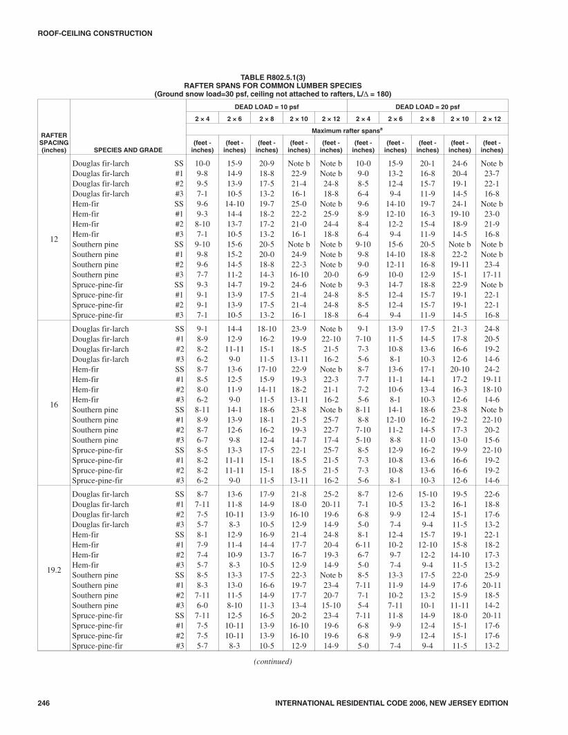
TABLE R802.5.1(3)RAFTER SPANS FOR COMMON LUMBER SPECIES
(Ground snow load=30 psf, ceiling not attached to rafters, L/Δ = 180)
RAFTERSPACING(inches) SPECIES AND GRADE
DEAD LOAD = 10 psf DEAD LOAD = 20 psf
2 × 4 2 × 6 2 × 8 2 × 10 2 × 12 2 × 4 2 × 6 2 × 8 2 × 10 2 × 12
Maximum rafter spansa
(feet -inches)
(feet -inches)
(feet -inches)
(feet -inches)
(feet -inches)
(feet -inches)
(feet -inches)
(feet -inches)
(feet -inches)
(feet -inches)
12
Douglas fir-larch SSDouglas fir-larch #1Douglas fir-larch #2Douglas fir-larch #3Hem-fir SSHem-fir #1Hem-fir #2Hem-fir #3Southern pine SSSouthern pine #1Southern pine #2Southern pine #3Spruce-pine-fir SSSpruce-pine-fir #1Spruce-pine-fir #2Spruce-pine-fir #3
10-09-89-57-19-69-38-107-19-109-89-67-79-39-19-17-1
15-914-913-910-514-1014-413-710-515-615-214-511-214-713-913-910-5
20-918-817-513-219-718-217-213-220-520-018-814-319-217-517-513-2
Note b22-921-416-125-022-221-016-1
Note b24-922-316-1024-621-421-416-1
Note bNote b24-818-8
Note b25-924-418-8
Note bNote bNote b20-0
Note b24-824-818-8
10-09-08-56-49-68-98-46-49-109-89-06-99-38-58-56-4
15-913-212-49-4
14-1012-1012-29-415-614-1012-1110-014-712-412-49-4
20-116-815-711-919-716-315-411-920-518-816-812-918-815-715-711-9
24-620-419-114-524-1
19-1018-914-5
Note b22-2
19-1115-122-919-119-114-5
Note b23-722-116-8
Note b23-021-916-8
Note bNote b23-4
17-11Note b22-122-116-8
16
Douglas fir-larch SSDouglas fir-larch #1Douglas fir-larch #2Douglas fir-larch #3Hem-fir SSHem-fir #1Hem-fir #2Hem-fir #3Southern pine SSSouthern pine #1Southern pine #2Southern pine #3Spruce-pine-fir SSSpruce-pine-fir #1Spruce-pine-fir #2Spruce-pine-fir #3
9-18-98-26-28-78-58-06-28-118-98-76-78-58-28-26-2
14-412-911-119-013-612-511-99-014-113-912-69-813-311-1111-119-0
18-1016-215-111-517-1015-914-1111-518-618-116-212-417-515-115-111-5
23-919-918-513-1122-919-318-213-1123-821-519-314-722-118-518-513-11
Note b22-1021-516-2
Note b22-321-116-2
Note b25-722-717-425-721-521-516-2
9-17-107-35-68-77-77-25-68-118-87-105-108-57-37-35-6
13-911-510-88-113-611-110-68-114-112-1011-28-812-910-810-88-1
17-514-513-610-317-114-113-410-318-616-214-511-016-213-613-610-3
21-317-816-612-6
20-1017-216-312-623-819-217-313-019-916-616-612-6
24-820-519-214-624-2
19-1118-1014-6
Note b22-1020-215-6
22-1019-219-214-6
19.2
Douglas fir-larch SSDouglas fir-larch #1Douglas fir-larch #2Douglas fir-larch #3Hem-fir SSHem-fir #1Hem-fir #2Hem-fir #3Southern pine SSSouthern pine #1Southern pine #2Southern pine #3Spruce-pine-fir SSSpruce-pine-fir #1Spruce-pine-fir #2Spruce-pine-fir #3
8-77-117-55-78-17-97-45-78-58-37-116-07-117-57-55-7
13-611-810-118-312-911-410-98-313-313-011-58-1012-510-1110-118-3
17-914-913-910-516-914-413-710-517-516-614-911-316-513-913-910-5
21-818-016-1012-921-417-716-712-922-319-717-713-420-216-1016-1012-9
25-220-1119-614-924-820-419-314-9
Note b23-420-715-1023-419-619-614-9
8-77-16-85-08-16-116-75-08-57-117-15-47-116-86-85-0
12-610-59-97-412-410-29-77-413-311-910-27-1111-89-99-97-4
15-1013-212-49-415-712-1012-29-417-514-913-210-114-912-412-49-4
19-516-115-111-519-115-8
14-1011-522-017-615-9
11-1118-015-115-111-5
22-618-817-613-222-118-217-313-225-9
20-1118-514-2
20-1117-617-613-2
(continued)
1208_NJ_Res_2006.prnM:\data\CODES\STATE CODES\New Jersey\2006\NJ_Res_2006\Final VP_Chgo\08_NJ_Res_2006.vpTuesday, April 17, 2007 11:32:27 AM
Color profile: Generic CMYK printer profileComposite Default screen

INTERNATIONAL RESIDENTIAL CODE 2006, NEW JERSEY EDITION 247
ROOF-CEILING CONSTRUCTION
TABLE R802.5.1(3)—continuedRAFTER SPANS FOR COMMON LUMBER SPECIES
(Ground snow load=30 psf, ceiling not attached to rafters, L/Δ = 180)
RAFTERSPACING(inches) SPECIES AND GRADE
DEAD LOAD = 10 psf DEAD LOAD = 20 psf
2 × 4 2 × 6 2 × 8 2 × 10 2 × 12 2 × 4 2 × 6 2 × 8 2 × 10 2 × 12
Maximum rafter spansa
(feet -inches)
(feet -inches)
(feet -inches)
(feet -inches)
(feet -inches)
(feet -inches)
(feet -inches)
(feet -inches)
(feet -inches)
(feet -inches)
24
Douglas fir-larch SSDouglas fir-larch #1Douglas fir-larch #2Douglas fir-larch #3Hem-fir SSHem-fir #1Hem-fir #2Hem-fir #3Southern pine SSSouthern pine #1Southern pine #2Southern pine #3Spruce-pine-fir SSSpruce-pine-fir #1Spruce-pine-fir #2Spruce-pine-fir #3
7-117-16-85-0
12-610-59-97-4
15-1013-212-49-4
19-516-115-111-5
22-618-817-613-2
7-86-45-114-6
11-39-48-86-7
14-211-911-08-4
17-414-513-610-2
20-116-815-7
11-107-66-116-75-07-107-87-15-47-46-86-85-0
11-1010-29-77-412-311-910-27-1111-79-99-97-4
15-712-1012-29-416-214-913-210-114-912-412-49-4
19-115-814-1011-520-817-615-911-1118-015-115-111-5
22-118-217-313-225-120-1118-514-220-1117-617-613-2
7-66-25-104-67-107-16-44-97-15-115-114-6
11-09-18-76-712-310-69-27-110-58-88-86-7
13-1111-610-108-4
16-213-211-99-0
13-211-011-08-4
17-014-013-310-219-815-814-110-816-113-613-610-2
19-916-315-5
11-1023-018-816-612-818-815-715-7
11-10
Check sources for availability of lumber in lengths greater than 20 feet.For SI: 1 inch = 25.4 mm, 1 foot = 304.8 mm, 1 pound per square foot = 0.0479kPa.a. The tabulated rafter spans assume that ceiling joists are located at the bottom of the attic space or that some other method of resisting the outward push of the rafters
on the bearing walls, such as rafter ties, is provided at that location. When ceiling joists or rafter ties are located higher in the attic space, the rafter spans shall bemultiplied by the factors given below:
HC/HR Rafter Span Adjustment Factor
1/3 0.67
1/4 0.76
1/5 0.83
1/6 0.90
1/7.5 or less 1.00
where:HC = Height of ceiling joists or rafter ties measured vertically above the top of the rafter support walls.HR = Height of roof ridge measured vertically above the top of the rafter support walls.
b. Span exceeds 26 feet in length.
1308_NJ_Res_2006.prnM:\data\CODES\STATE CODES\New Jersey\2006\NJ_Res_2006\Final VP_Chgo\08_NJ_Res_2006.vpTuesday, April 17, 2007 11:32:27 AM
Color profile: Generic CMYK printer profileComposite Default screen

248 INTERNATIONAL RESIDENTIAL CODE 2006, NEW JERSEY EDITION
ROOF-CEILING CONSTRUCTION
TABLE R802.5.1(4)RAFTER SPANS FOR COMMON LUMBER SPECIES
(Ground snow load=50 psf, ceiling not attached to rafters, L/Δ = 180)
RAFTERSPACING(inches) SPECIES AND GRADE
DEAD LOAD = 10 psf DEAD LOAD = 20 psf
2 × 4 2 × 6 2 × 8 2 × 10 2 × 12 2 × 4 2 × 6 2 × 8 2 × 10 2 × 12
Maximum rafter spansa
(feet -inches)
(feet -inches)
(feet -inches)
(feet -inches)
(feet -inches)
(feet -inches)
(feet -inches)
(feet -inches)
(feet -inches)
(feet -inches)
12
Douglas fir-larch SSDouglas fir-larch #1Douglas fir-larch #2Douglas fir-larch #3Hem-fir SSHem-fir #1Hem-fir #2Hem-fir #3Southern pine SSSouthern pine #1Southern pine #2Southern pine #3Spruce-pine-fir SSSpruce-pine-fir #1Spruce-pine-fir #2Spruce-pine-fir #3
8-58-27-85-108-07-107-55-108-48-28-06-27-107-87-85-10
13-312-011-38-612-611-911-18-613-012-1011-99-212-311-311-38-6
17-615-314-310-916-614-1014-010-917-216-1015-311-816-214-314-310-9
22-418-717-513-221-118-117-213-221-1120-318-213-920-817-517-513-2
26-021-720-215-325-621-019-1115-3
Note b24-121-316-424-120-215-220-3
8-57-77-15-58-07-57-05-58-48-27-75-97-107-17-15-5
13-311-210-57-1012-610-1010-37-1013-012-610-118-512-310-510-57-10
17-014-113-210-016-613-913-010-017-215-914-110-915-913-213-210-0
20-917-316-112-220-416-9
15-1012-2
21-1118-9
16-1012-919-316-116-112-2
24-020-018-814-123-719-518-514-1
Note b22-419-915-222-418-818-814-1
16
Douglas fir-larch SSDouglas fir-larch #1Douglas fir-larch #2Douglas fir-larch #3Hem-fir SSHem-fir #1Hem-fir #2Hem-fir #3Southern pine SSSouthern pine #1Southern pine #2Southern pine #3Spruce-pine-fir SSSpruce-pine-fir #1Spruce-pine-fir #2Spruce-pine-fir #3
7-87-16-85-07-36-116-75-07-67-57-15-47-16-86-85-0
12-110-59-97-411-510-29-77-4
11-1011-710-27-1111-29-99-97-4
15-1013-212-49-415-012-1012-29-415-714-913-210-114-812-412-49-4
19-516-115-111-519-115-814-1011-519-1117-615-911-1118-015-115-111-5
22-618-817-613-222-118-217-313-224-320-1118-514-220-1117-617-613-2
7-86-76-24-87-36-56-14-87-67-46-74-117-16-26-24-8
11-79-89-06-1011-59-58-116-1011-1010-109-57-410-99-09-06-10
14-812-211-58-814-511-1111-38-815-713-812-29-413-811-511-58-8
17-1114-1113-1110-617-814-613-910-6
19-1116-214-711-0
15-1113-1113-1110-6
20-1017-316-212-320-5
16-1015-1112-3
23-1019-417-113-119-416-216-212-3
19.2
Douglas fir-larch SSDouglas fir-larch #1Douglas fir-larch #2Douglas fir-larch #3Hem-fir SSHem-fir #1Hem-fir #2Hem-fir #3Southern pine SSSouthern pine #1Southern pine #2Southern pine #3Spruce-pine-fir SSSpruce-pine-fir #1Spruce-pine-fir #2Spruce-pine-fir #3
7-36-66-14-76-106-46-04-77-17-06-64-116-86-16-14-7
11-49-68-116-910-99-38-96-911-210-89-47-310-68-118-116-9
14-612-011-38-614-211-911-18-614-813-512-09-213-511-311-38-6
17-814-813-910-517-514-413-710-518-916-014-410-1016-513-913-910-5
20-617-115-1112-120-216-715-912-122-1019-116-1012-1119-115-1115-1112-1
7-36-05-74-36-105-105-74-37-16-86-04-66-85-75-74-3
10-78-108-36-310-58-78-16-311-29-118-86-89-108-38-36-3
13-511-210-57-1113-210-1010-37-1114-812-511-28-6
12-510-510-57-11
16-513-712-99-7
16-113-312-79-718 7
14-1013-410-115-312-912-99-7
19-015-914-911-218-815-514-711-221-917-815-712-017-814-914-911-2
(continued)
1408_NJ_Res_2006.prnM:\data\CODES\STATE CODES\New Jersey\2006\NJ_Res_2006\Final VP_Chgo\08_NJ_Res_2006.vpTuesday, April 17, 2007 11:32:28 AM
Color profile: Generic CMYK printer profileComposite Default screen

INTERNATIONAL RESIDENTIAL CODE 2006, NEW JERSEY EDITION 249
ROOF-CEILING CONSTRUCTION
TABLE R802.5.1(4)—continuedRAFTER SPANS FOR COMMON LUMBER SPECIES
(Ground snow load=50 psf, ceiling not attached to rafters, L/Δ = 180)
RAFTERSPACING(inches) SPECIES AND GRADE
DEAD LOAD = 10 psf DEAD LOAD = 20 psf
2 × 4 2 × 6 2 × 8 2 × 10 2 × 12 2 × 4 2 × 6 2 × 8 2 × 10 2 × 12
Maximum rafter spansa
(feet -inches)
(feet -inches)
(feet -inches)
(feet -inches)
(feet -inches)
(feet -inches)
(feet -inches)
(feet -inches)
(feet -inches)
(feet -inches)
24
Douglas fir-larch SSDouglas fir-larch #1Douglas fir-larch #2Douglas fir-larch #3Hem-fir SSHem-fir #1Hem-fir #2Hem-fir #3Southern pine SSSouthern pine #1Southern pine #2Southern pine #3Spruce-pine-fir SSSpruce-pine-fir #1Spruce-pine-fir #2Spruce-pine-fir #3
6-85-105-54-16-45-85-44-16-76-55-104-46-25-55-54-1
10-8-67-116-09-118-37-106-010-49-78-46-59-67-117-116-0
13-010-910-17-7
12-910-69-117-713-812-010-98-312-010-110-17-7
15-1013-212-49-4
15-712-1012-19-417-514-412-109-914-812-412-49-4
18-415-314-310-918-014-1014-110-921-017-115-111-717-114-314-310-9
6-65-55-03-106-45-34-113-106-76-05-54-16-05-05-03-10
9-67-107-45-79-47-87-35-710-48-107-96-08-107-47-45-7
12-010-09-47-111-99-99-27-113-811-210-07-711-29-49-47-1
14-812-211-58-7
14-511-1011-38-7
16-713-3
11-119-0
13-711-511-58-7
17-014-113-210-016-813-913-010-019-515-9
13-1110-815-913-213-210-0
Check sources for availability of lumber in lengths greater than 20 feet.For SI: 1 inch = 25.4 mm, 1 foot = 304.8 mm, 1 pound per square foot = 0.0479kPa.a. The tabulated rafter spans assume that ceiling joists are located at the bottom of the attic space or that some other method of resisting the outward push of the rafters
on the bearing walls, such as rafter ties, is provided at that location. When ceiling joists or rafter ties are located higher in the attic space, the rafter spans shall bemultiplied by the factors given below:
HC/HR Rafter Span Adjustment Factor
1/3 0.67
1/4 0.76
1/5 0.83
1/6 0.90
1/7.5 or less 1.00
where:HC = Height of ceiling joists or rafter ties measured vertically above the top of the rafter support walls.HR = Height of roof ridge measured vertically above the top of the rafter support walls.
b. Span exceeds 26 feet in length.
1508_NJ_Res_2006.prnM:\data\CODES\STATE CODES\New Jersey\2006\NJ_Res_2006\Final VP_Chgo\08_NJ_Res_2006.vpTuesday, April 17, 2007 11:32:28 AM
Color profile: Generic CMYK printer profileComposite Default screen

250 INTERNATIONAL RESIDENTIAL CODE 2006, NEW JERSEY EDITION
ROOF-CEILING CONSTRUCTION
TABLE R802.5.1(5)RAFTER SPANS FOR COMMON LUMBER SPECIES
(Ground snow load=30 psf, ceiling attached to rafters, L/Δ = 240)
RAFTERSPACING(inches) SPECIES AND GRADE
DEAD LOAD = 10 psf DEAD LOAD = 20 psf
2 × 4 2 × 6 2 × 8 2 × 10 2 × 12 2 × 4 2 × 6 2 × 8 2 × 10 2 × 12
Maximum rafter spansa
(feet -inches)
(feet -inches)
(feet -inches)
(feet -inches)
(feet -inches)
(feet -inches)
(feet -inches)
(feet -inches)
(feet -inches)
(feet -inches)
12
Douglas fir-larch SSDouglas fir-larch #1Douglas fir-larch #2Douglas fir-larch #3Hem-fir SSHem-fir #1Hem-fir #2Hem-fir #3Southern pine SSSouthern pine #1Southern pine #2Southern pine #3Spruce-pine-fir SSSpruce-pine-fir #1Spruce-pine-fir #2Spruce-pine-fir #3
9-18-98-77-18-78-58-07-18-118-98-77-78-58-38-37-1
14-413-913-610-513-613-312-710-514-113-913-611-213-312-1112-1110-5
18-1018-217-513-217-1017-516-713-218-618-217-1014-317-517-017-013-2
24-122-921-416-122-922-221-016-123-823-222-316-1022-321-421-416-1
Note bNote b24-818-8
Note b25-924-418-8
Note bNote bNote b20-0
Note b24-824-818-8
9-18-98-56-48-78-58-06-48-118-98-76-98-58-38-36-4
14-413-212-49-413-612-1012-29-414-113-912-1110-013-312-412-49-4
18-1016-815-711-917-1016-315-411-918-618-216-812-917-515-715-711-9
24-120-419-114-522-9
19-1018-914-523-822-2
19-1115-122-319-119-114-5
Note b23-722-116-8
Note b23-021-916-8
Note bNote b23-4
17-11Note b22-122-116-8
16
Douglas fir-larch SSDouglas fir-larch #1Douglas fir-larch #2Douglas fir-larch #3Hem-fir SSHem-fir #1Hem-fir #2Hem-fir #3Southern pine SSSouthern pine #1Southern pine #2Southern pine #3Spruce-pine-fir SSSpruce-pine-fir #1Spruce-pine-fir #2Spruce-pine-fir #3
8-38-07-106-27-107-87-36-28-18-07-106-77-87-67-66-2
13-012-611-119-012-312-011-59-012-912-612-39-812-011-911-99-0
17-216-215-111-516-215-914-1111-516-1016-616-212-415-1015-115-111-5
21-1019-918-513-1120-819-318-213-1121-621-119-314-720-218-518-513-11
Note b22-1021-516-225-122-321-116-2
Note b25-722-717-424-721-521-516-2
8-37-107-35-67-107-77-25-68-18-07-105-107-87-37-35-6
13-011-510-88-112-311-110-68-112-912-611-28-812-010-810-88-1
17-214-513-610-316-214-113-410-316-1016-214-511-015-1013-613-610-3
21-317-816-612-620-817-216-312-621-619-217-313-019-916-616-612-6
24-820-519-214-624-2
19-1118-1014-6
Note b22-1020-215-6
22-1019-219-214-6
19.2
Douglas fir-larch SSDouglas fir-larch #1Douglas fir-larch #2Douglas fir-larch #3Hem-fir SSHem-fir #1Hem-fir #2Hem-fir #3Southern pine SSSouthern pine #1Southern pine #2Southern pine #3Spruce-pine-fir SSSpruce-pine-fir #1Spruce-pine-fir #2Spruce-pine-fir #3
7-97-67-45-77-47-26-105-77-87-67-46-07-27-07-05-7
12-311-810-118-311-711-410-98-312-011-911-58-1011-410-1110-118-3
16-114-913-910-515-314-413-710-515-1015-614-911-314-1113-913-910-5
20-718-016-1012-919-517-716-712-920-219-717-713-419-016-1016-1012-9
25-020-1119-614-923-720-419-314-924-723-420-715-1023-119-619-614-9
7-97-16-85-07-46-116-75-07-87-67-15-47-26-86-85-0
12-310-59-97-411-710-29-77-412-011-910-27-1111-49-99-97-4
15-1013-212-49-415-312-1012-29-4
15-1014-913-210-114-912-412-49-4
19-516-115-111-519-115-8
14-1011-520-217-615-911-1118-015-115-111-5
22-618-817-613-222-118-217-313-224-7
20-1118-514-220-1117-617-613-2
(continued)
1608_NJ_Res_2006.prnM:\data\CODES\STATE CODES\New Jersey\2006\NJ_Res_2006\Final VP_Chgo\08_NJ_Res_2006.vpTuesday, April 17, 2007 11:32:28 AM
Color profile: Generic CMYK printer profileComposite Default screen

INTERNATIONAL RESIDENTIAL CODE 2006, NEW JERSEY EDITION 251
ROOF-CEILING CONSTRUCTION
TABLE R802.5.1(5)—continuedRAFTER SPANS FOR COMMON LUMBER SPECIES
(Ground snow load=30 psf, ceiling attached to rafters, L/Δ = 240)
RAFTERSPACING(inches) SPECIES AND GRADE
DEAD LOAD = 10 psf DEAD LOAD = 20 psf
2 × 4 2 × 6 2 × 8 2 × 10 2 × 12 2 × 4 2 × 6 2 × 8 2 × 10 2 × 12
Maximum rafter spansa
(feet-inches)
(feet-inches)
(feet-inches)
(feet-inches)
(feet-inches)
(feet-inches)
(feet-inches)
(feet-inches)
(feet-inches)
(feet-inches)
24
Douglas fir-larch SSDouglas fir-larch #1Douglas fir-larch #2Douglas fir-larch #3Hem-fir SSHem-fir #1Hem-fir #2Hem-fir #3Southern pine SSSouthern pine #1Southern pine #2Southern pine #3Spruce-pine-fir SSSpruce-pine-fir #1Spruce-pine-fir #2Spruce-pine-fir #3
7-37-06-85-0
6-106-86-45-07-17-06-105-46-86-66-65-0
11-410-59-97-4
10-910-29-77-411-210-1110-27-1110-69-99-97-4
15-013-212-49-414-212-1012-29-414-814-513-210-113-1012-412-49-4
19-116-115-111-518-015-814-1011-518-917-615-911-1117-815-115-111-5
22-618-817-613-2
21-1118-217-313-222-1020-1118-514-220-1117-617-613-2
7-36-45-114-6
6-106-25-104-67-17-06-44-96-85-115-114-6
11-39-48-86-7
10-99-18-76-711-210-69-27-110-58-88-86-7
14-211-911-08-4
13-1111-610-108-4
14-813-211-99-0
13-211-011-08-4
17-414-513-610-217-014-013-310-218-915-814-110-816-113-613-610-2
20-116-815-7
11-1019-916-315-5
11-1022-1018-816-612-818-815-715-7
11-10
Check sources for availability of lumber in lengths greater than 20 feet.For SI: 1 inch = 25.4 mm, 1 foot = 304.8 mm, 1 pound per square foot = 0.0479kPa.a. The tabulated rafter spans assume that ceiling joists are located at the bottom of the attic space or that some other method of resisting the outward push of the rafters
on the bearing walls, such as rafter ties, is provided at that location. When ceiling joists or rafter ties are located higher in the attic space, the rafter spans shall bemultiplied by the factors given below:
HC/HR Rafter Span Adjustment Factor
1/3 0.67
1/4 0.76
1/5 0.83
1/6 0.90
1/7.5 or less 1.00
where:HC = Height of ceiling joists or rafter ties measured vertically above the top of the rafter support walls.HR = Height of roof ridge measured vertically above the top of the rafter support walls.
b. Span exceeds 26 feet in length.
1708_NJ_Res_2006.prnM:\data\CODES\STATE CODES\New Jersey\2006\NJ_Res_2006\Final VP_Chgo\08_NJ_Res_2006.vpTuesday, April 17, 2007 11:32:28 AM
Color profile: Generic CMYK printer profileComposite Default screen

252 INTERNATIONAL RESIDENTIAL CODE 2006, NEW JERSEY EDITION
ROOF-CEILING CONSTRUCTION
TABLE R802.5.1(6)RAFTER SPANS FOR COMMON LUMBER SPECIES
(Ground snow load=50 psf, ceiling attached to rafters, L/Δ = 240)
RAFTERSPACING(inches) SPECIES AND GRADE
DEAD LOAD = 10 psf DEAD LOAD = 20 psf
2 × 4 2 × 6 2 × 8 2 × 10 2 × 12 2 × 4 2 × 6 2 × 8 2 × 10 2 × 12
Maximum rafter spansa
(feet-inches)
(feet-inches)
(feet-inches)
(feet-inches)
(feet-inches)
(feet-inches)
(feet-inches)
(feet-inches)
(feet-inches)
(feet-inches)
12
Douglas fir-larch SSDouglas fir-larch #1Douglas fir-larch #2Douglas fir-larch #3Hem-fir SSHem-fir #1Hem-fir #2Hem-fir #3Southern pine SSSouthern pine #1Southern pine #2Southern pine #3Spruce-pine-fir SSSpruce-pine-fir #1Spruce-pine-fir #2Spruce-pine-fir #3
7-87-57-35-107-37-16-95-107-67-57-36-27-16-116-115-10
12-111-711-38-611-511-210-88-6
11-1011-711-59-211-210-1110-118-6
15-1115-314-310-915-014-814-010-915-715-415-011-814-814-314-310-9
20-318-717-513-219-218-117-213-219-1119-718-213-918-917-517-513-2
24-821-720-215-323-421-019-1115-324-323-921-316-422-1020-220-215-3
7-87-57-15-57-37-16-95-57-67-57-35-97-16-116-115-5
12-111-210-57-1011-510-1010-37-1011-1011-710-118-511-210-510-57-10
15-1114-113-210-015-013-913-010-015-715-414-110-914-813-213-210-0
20-317-316-112-219-216-9
15-1012-2
19-1118-9
16-1012-918-916-116-112-2
24-020-018-814-123-419-518-514-124-322-419-915-222-418-818-814-1
16
Douglas fir-larch SSDouglas fir-larch #1Douglas fir-larch #2Douglas fir-larch #3Hem-fir SSHem-fir #1Hem-fir #2Hem-fir #3Southern pine SSSouthern pine #1Southern pine #2Southern pine #3Spruce-pine-fir SSSpruce-pine-fir #1Spruce-pine-fir #2Spruce-pine-fir #3
7-06-96-75-06-76-56-25-06-106-96-75-46-56-46-45-0
11-010-59-97-410-410-29-77-410-910-710-27-1110-29-99-97-4
14-513-212-49-413-812-1012-29-414-213-1113-210-113-412-412-49-4
18-516-115-111-517-515-814-1011-518-117-615-911-1117-015-115-111-5
22-518-817-613-221-218-217-313-222-020-1118-514-220-917-617-613-2
7-06-76-24-86-76-56-14-86-106-96-74-116-56-26-24-8
11-09-89-06-1010-49-58-116-1010-910-79-57-410-29-09-06-10
14-512-211-58-813-811-1111-38-814-213-812-29-413-411-511-58-8
17-1114-1113-1110-617-514-613-910-618-116-214-711-016-8
13-1113-1110-6
20-1017-316-212-320-5
16-1015-1112-322-019-417-113-119-416-216-212-3
19.2
Douglas fir-larch SSDouglas fir-larch #1Douglas fir-larch #2Douglas fir-larch #3Hem-fir SSHem-fir #1Hem-fir #2Hem-fir #3Southern pine SSSouthern pine #1Southern pine #2Southern pine #3Spruce-pine-fir SSSpruce-pine-fir #1Spruce-pine-fir #2Spruce-pine-fir #3
6-76-46-14-76-26-15-94-76-56-46-24-116-15-115-114-7
10-49-68-116-99-99-38-96-910-29-119-47-39-68-118-116-9
13-712-011-38-6
12-1011-911-18-613-413-112-09-212-711-311-38-6
17-414-813-910-516-514-413-710-517-016-014-410-1016-013-913-910-5
20-617-115-1112-119-1116-715-912-120-919-116-1012-1119-1
15-1115-1112-1
6-76-05-74-36-25-105-74-36-56-46-04-66-15-75-74-3
10-48-108-36-39-98-78-16-310-29-118-86-89-68-38-36-3
13-511-210-57-1112-1010-1010-37-1113-412-511-28-612-510-510-57-11
16-513-712-99-7
16-113-312-79-7
17-014-1013-410-115-312-912-99-7
19-015-914-911-218-815-514-711-220-917-815-712-017-814-914-911-2
(continued)
1808_NJ_Res_2006.prnM:\data\CODES\STATE CODES\New Jersey\2006\NJ_Res_2006\Final VP_Chgo\08_NJ_Res_2006.vpTuesday, April 17, 2007 11:32:29 AM
Color profile: Generic CMYK printer profileComposite Default screen

INTERNATIONAL RESIDENTIAL CODE 2006, NEW JERSEY EDITION 253
ROOF-CEILING CONSTRUCTION
TABLE R802.5.1(6)—continuedRAFTER SPANS FOR COMMON LUMBER SPECIES
(Ground snow load=50 psf, ceiling attached to rafters, L/Δ = 240)
RAFTERSPACING(inches) SPECIES AND GRADE
DEAD LOAD = 10 psf DEAD LOAD = 20 psf
2 × 4 2 × 6 2 × 8 2 × 10 2 × 12 2 × 4 2 × 6 2 × 8 2 × 10 2 × 12
Maximum rafter spansa
(feet-inches)
(feet-inches)
(feet-inches)
(feet-inches)
(feet-inches)
(feet-inches)
(feet-inches)
(feet-inches)
(feet-inches)
(feet-inches)
24
Douglas fir-larch SSDouglas fir-larch #1Douglas fir-larch #2Douglas fir-larch #3Hem-fir SSHem-fir #1Hem-fir #2Hem-fir #3Southern pine SSSouthern pine #1Southern pine #2Southern pine #3Spruce-pine-fir SSSpruce-pine-fir #1Spruce-pine-fir #2Spruce-pine-fir #3
6-15-105-54-15-95-85-44-16-05-105-94-45-85-55-54-1
9-78-67-116-09-18-37-106-09-59-38-46-58-107-117-116-0
12-710-910-17-7
11-1110-69-117-712-512-010-98-311-810-110-17-7
15-1013-212-49-415-212-1012-19-4
15-1014-412-109-914-812-412-49-4
18-415-314-310-918-014-1014-110-919-317-115-111-717-114-314-310-9
6-15-55-03-105-95-34-113-106-05-105-54-15-85-05-03-10
9-67-107-45-79-17-87-35-79-58-107-96-08-107-47-45-7
12-010-09-47-1
11-99-99-27-1
12-511-210-07-7
11-29-49-47-1
14-812-211-58-7
14-511-1011-38-7
15-1013-3
11-119-0
13-711-511-58-7
17-014-113-210-0
15-1113-913-010-019-315-9
13-1110-815-913-213-210-0
Check sources for availability of lumber in lengths greater than 20 feet.For SI: 1 inch = 25.4 mm, 1 foot = 304.8 mm, 1 pound per square foot = 0.0479kPa.a. The tabulated rafter spans assume that ceiling joists are located at the bottom of the attic space or that some other method of resisting the outward push of the rafters
on the bearing walls, such as rafter ties, is provided at that location. When ceiling joists or rafter ties are located higher in the attic space, the rafter spans shall bemultiplied by the factors given below:
HC/HR Rafter Span Adjustment Factor
1/3 0.67
1/4 0.76
1/5 0.83
1/6 0.90
1/7.5 or less 1.00
where:HC = Height of ceiling joists or rafter ties measured vertically above the top of the rafter support walls.HR = Height of roof ridge measured vertically above the top of the rafter support walls.
1908_NJ_Res_2006.prnM:\data\CODES\STATE CODES\New Jersey\2006\NJ_Res_2006\Final VP_Chgo\08_NJ_Res_2006.vpTuesday, April 17, 2007 11:32:29 AM
Color profile: Generic CMYK printer profileComposite Default screen

254 INTERNATIONAL RESIDENTIAL CODE 2006, NEW JERSEY EDITION
ROOF-CEILING CONSTRUCTION
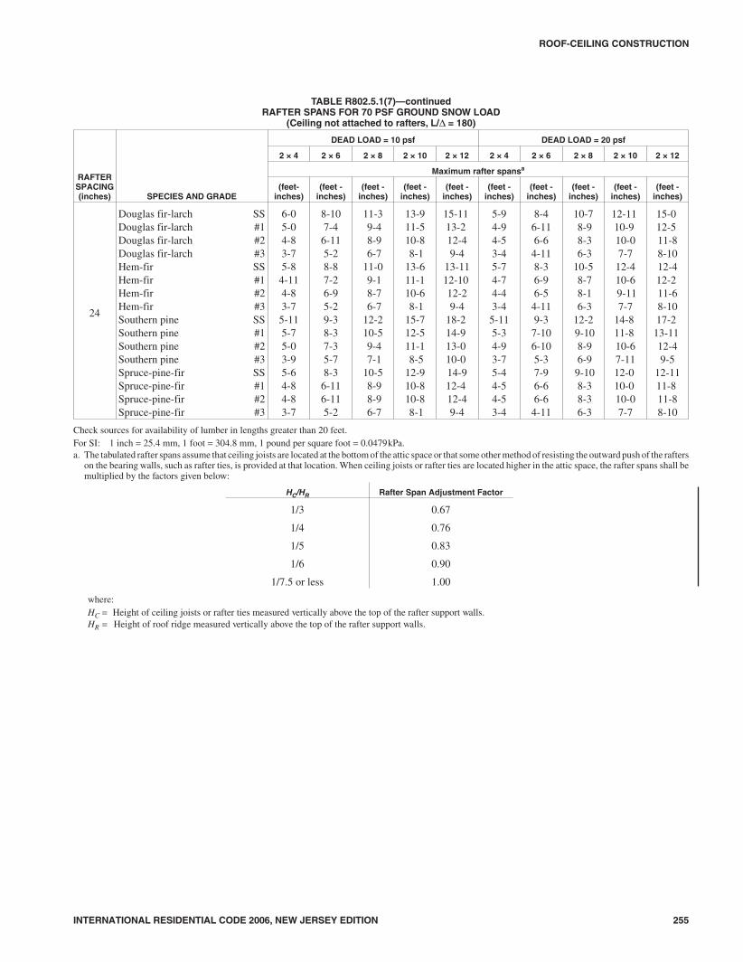
TABLE R802.5.1(7)RAFTER SPANS FOR 70 PSF GROUND SNOW LOAD
(Ceiling not attached to rafters, L/Δ = 180)
RAFTERSPACING(inches) SPECIES AND GRADE
DEAD LOAD = 10 psf DEAD LOAD = 20 psf
2 × 4 2 × 6 2 × 8 2 × 10 2 × 12 2 × 4 2 × 6 2 × 8 2 × 10 2 × 12
Maximum Rafter Spansa
(feet-inches)
(feet-inches)
(feet-inches)
(feet-inches)
(feet-inches)
(feet-inches)
(feet-inches)
(feet-inches)
(feet-inches)
(feet-inches)
12
Douglas fir-larch SSDouglas fir-larch #1Douglas fir-larch #2Douglas fir-larch #3Hem-fir SSHem-fir #1Hem-fir #2Hem-fir #3Southern pine SSSouthern pine #1Southern pine #2Southern pine #3Spruce-pine-fir SSSpruce-pine-fir #1Spruce-pine-fir #2Spruce-pine-fir #3
7-77-16-85-07-26-116-75-07-57-37-15-47-06-86-85-0
11-1010-59-97-4
11-310-29-77-4
11-811-510-27-1111-09-99-97-4
15-813-212-49-4
14-912-1012-29-4
15-414-913-210-114-612-412-49-4
19-516-115-111-518-1015-814-1011-519-717-615-911-1118-015-115-111-5
22-618-817-613-222-118-217-313-223-1020-1118-514-220-1117-617-613-2
7-76-86-34-97-26-66-24-97-57-36-85-17-06-36-34-9
11-109-109-26-1111-39-79-16-1111-811-19-77-5
11-09-29-26-11
15-012-511-88-9
14-812-111-58-9
15-413-1112-59-6
13-1111-811-88-9
18-315-214-210-918-0
14-1014-010-919-716-6
14-1011-317-014-214-210-9
21-217-716-612-5
20-1017-216-312-5
23-1019-817-513-419-816-616-612-5
16
Douglas fir-larch SSDouglas fir-larch #1Douglas fir-larch #2Douglas fir-larch #3Hem-fir SSHem-fir #1Hem-fir #2Hem-fir #3Southern pine SSSouthern pine #1Southern pine #2Southern pine #3Spruce-pine-fir SSSpruce-pine-fir #1Spruce-pine-fir #2Spruce-pine-fir #3
6-106-25-94-46-66-05-84-46-96-76-24-86-45-95-94-4
10-99-08-56-4
10-28-98-46-4
10-710-28-106-1010-08-58-56-4
13-911-510-88-1
13-511-210-68-1
14-012-911-58-9
12-910-810-88-1
16-1013-1113-19-1016-613-712-109-10
17-1015-213-710-415-713-113-19-10
19-616-215-211-519-215-914-1111-521-818-116-012-318-115-215-211-5
6-105-105-54-16-65-85-44-16-96-55-104-46-45-55-54-1
10-38-67-116-0
10-18-37-106-0
10-79-78-46-59-67-117-116-0
13-010-910-17-7
12-910-69-117-7
14-012-010-98-3
12-010-110-17-7
15-1013-212-49-4
15-712-1012-19-4
17-1014-4
12-109-9
14-812-412-49-4
18-415-314-310-918-0
14-1014-110-921-017-115-111-717-114-314-310-9
19.2
Douglas fir-larch SSDouglas fir-larch #1Douglas fir-larch #2Douglas fir-larch #3Hem-fir SSHem-fir #1Hem-fir #2Hem-fir #3Southern pine SSSouthern pine #1Southern pine #2Southern pine #3Spruce-pine-fir SSSpruce-pine-fir #1Spruce-pine-fir #2Spruce-pine-fir #3
6-55-75-34-06-15-65-24-06-46-35-74-36-05-35-34-0
9-118-37-85-109-78-07-75-1010-09-38-16-39-27-87-85-10
12-710-59-97-4
12-410-29-77-4
13-211-810-58-0
11-89-99-97-4
15-412-911-11
9-015-112-511-99-0
16-913-1012-59-5
14-311-1111-11
9-0
17-914-913-1010-517-414-513-710-520-416-614-711-216-613-1013-1010-5
6-55-45-03-96-15-24-113-96-45-115-44-05-115-05-03-9
9-47-97-35-69-27-77-25-610-08-97-75-118-87-37-35-6
11-109-109-26-1111-89-79-16-1113-211-09-107-6
11-09-29-26-11
14-512-011-38-6
14-211-811-18-6
16-513-111-98-1013-511-311-38-6
16-913-1113-09-1015-513-712-109-1019-215-713-910-715-713-013-09-10
(continued)
2008_NJ_Res_2006.prnM:\data\CODES\STATE CODES\New Jersey\2006\NJ_Res_2006\Final VP_Chgo\08_NJ_Res_2006.vpTuesday, April 17, 2007 11:32:29 AM
Color profile: Generic CMYK printer profileComposite Default screen
INTERNATIONAL RESIDENTIAL CODE 2006, NEW JERSEY EDITION 255
ROOF-CEILING CONSTRUCTION
TABLE R802.5.1(7)—continuedRAFTER SPANS FOR 70 PSF GROUND SNOW LOAD
(Ceiling not attached to rafters, L/Δ = 180)
RAFTERSPACING(inches) SPECIES AND GRADE
DEAD LOAD = 10 psf DEAD LOAD = 20 psf
2 × 4 2 × 6 2 × 8 2 × 10 2 × 12 2 × 4 2 × 6 2 × 8 2 × 10 2 × 12
Maximum rafter spansa
(feet-inches)
(feet -inches)
(feet -inches)
(feet -inches)
(feet -inches)
(feet -inches)
(feet -inches)
(feet -inches)
(feet -inches)
(feet -inches)
24
Douglas fir-larch SSDouglas fir-larch #1Douglas fir-larch #2Douglas fir-larch #3Hem-fir SSHem-fir #1Hem-fir #2Hem-fir #3Southern pine SSSouthern pine #1Southern pine #2Southern pine #3Spruce-pine-fir SSSpruce-pine-fir #1Spruce-pine-fir #2Spruce-pine-fir #3
6-05-04-83-75-84-114-83-75-115-75-03-95-64-84-83-7
8-107-46-115-28-87-26-95-29-38-37-35-78-36-116-115-2
11-39-48-96-7
11-09-18-76-7
12-210-59-47-1
10-58-98-96-7
13-911-510-88-1
13-611-110-68-1
15-712-511-18-5
12-910-810-88-1
15-1113-212-49-4
13-1112-1012-29-4
18-214-913-010-014-912-412-49-4
5-94-94-53-45-74-74-43-45-115-34-93-75-44-54-53-4
8-46-116-64-118-36-96-54-119-37-106-105-37-96-66-64-11
10-78-98-36-3
10-58-78-16-3
12-29-108-96-9
9-108-38-36-3
12-1110-910-07-7
12-410-69-117-7
14-811-810-67-1112-010-010-07-7
15-012-511-88-1012-412-211-68-1017-2
13-1112-49-5
12-1111-811-88-10
Check sources for availability of lumber in lengths greater than 20 feet.For SI: 1 inch = 25.4 mm, 1 foot = 304.8 mm, 1 pound per square foot = 0.0479kPa.a. The tabulated rafter spans assume that ceiling joists are located at the bottom of the attic space or that some other method of resisting the outward push of the rafters
on the bearing walls, such as rafter ties, is provided at that location. When ceiling joists or rafter ties are located higher in the attic space, the rafter spans shall bemultiplied by the factors given below:
HC/HR Rafter Span Adjustment Factor
1/3 0.67
1/4 0.76
1/5 0.83
1/6 0.90
1/7.5 or less 1.00
where:HC = Height of ceiling joists or rafter ties measured vertically above the top of the rafter support walls.HR = Height of roof ridge measured vertically above the top of the rafter support walls.
2108_NJ_Res_2006.prnM:\data\CODES\STATE CODES\New Jersey\2006\NJ_Res_2006\Final VP_Chgo\08_NJ_Res_2006.vpTuesday, April 17, 2007 11:32:29 AM
Color profile: Generic CMYK printer profileComposite Default screen

256 INTERNATIONAL RESIDENTIAL CODE 2006, NEW JERSEY EDITION
ROOF-CEILING CONSTRUCTION
TABLE R802.5.1(8)RAFTER SPANS FOR 70 PSF GROUND SNOW LOAD
(Ceiling attached to rafters, L/Δ = 240)
RAFTERSPACING(inches) SPECIES AND GRADE
DEAD LOAD = 10 psf DEAD LOAD = 20 psf
2 × 4 2 × 6 2 × 8 2 × 10 2 × 12 2 × 4 2 × 6 2 × 8 2 × 10 2 × 12
Maximum rafter spansa
(feet -inches)
(feet -inches)
(feet -inches)
(feet -inches)
(feet -inches)
(feet -inches)
(feet -inches)
(feet -inches)
(feet -inches)
(feet -inches)
12
Douglas fir-larch SSDouglas fir-larch #1Douglas fir-larch #2Douglas fir-larch #3Hem-fir SSHem-fir #1Hem-fir #2Hem-fir #3Southern pine SSSouthern pine #1Southern pine #2Southern pine #3Spruce-pine-fir SSSpruce-pine-fir #1Spruce-pine-fir #2Spruce-pine-fir #3
6-106-76-65-06-66-46-15-06-96-76-65-46-46-26-25-0
10-910-59-97-4
10-210-09-67-4
10-710-510-27-1110-09-99-97-4
14-313-212-49-4
13-512-1012-29-4
14-013-813-210-113-212-412-49-4
18-216-115-111-517-215-814-1011-517-1017-615-911-1116-915-115-111-5
22-118-817-613-220-1018-217-313-221-820-1118-514-220-517-617-613-2
6-106-76-34-96-66-46-14-96-96-76-65-16-46-26-24-9
10-99-109-26-1110-29-79-16-1110-710-59-77-5
10-09-29-26-11
14-312-511-88-9
13-512-111-58-9
14-013-812-59-6
13-211-811-88-9
18-215-214-210-917-2
14-1014-010-9
17-1016-6
14-1011-316-914-214-210-9
21-217-716-612-5
20-1017-216-312-521-819-817-513-419-816-616-612-5
16
Douglas fir-larch SSDouglas fir-larch #1Douglas fir-larch #2Douglas fir-larch #3Hem-fir SSHem-fir #1Hem-fir #2Hem-fir #3Southern pine SSSouthern pine #1Southern pine #2Southern pine #3Spruce-pine-fir SSSpruce-pine-fir #1Spruce-pine-fir #2Spruce-pine-fir #3
6-36-05-94-45-115-95-64-46-16-05-114-85-95-85-84-4
9-109-08-56-49-38-98-46-49-79-58-106-109-18-58-56-4
12-1111-510-88-1
12-211-210-68-1
12-812-511-58-9
11-1110-810-88-1
16-613-1113-19-1015-713-712-109-1016-215-213-710-415-313-113-19-10
19-616-215-211-518-1115-914-1111-519-818-116-012-318-115-215-211-5
6-35-105-54-15-115-85-44-16-16-05-104-45-95-55-54-1
9-108-67-116-09-38-37-106-09-79-58-46-59-17-117-116-0
12-1110-910-17-7
12-210-69-117-7
12-812-010-98-3
11-1110-110-17-7
15-1013-212-49-4
15-712-1012-19-4
16-214-4
12-109-9
14-812-412-49-4
18-415-314-310-918-0
14-1014-110-919-817-115-111-717-114-314-310-9
19.2
Douglas fir-larch SSDouglas fir-larch #1Douglas fir-larch #2Douglas fir-larch #3Hem-fir SSHem-fir #1Hem-fir #2Hem-fir #3Southern pine SSSouthern pine #1Southern pine #2Southern pine #3Spruce-pine-fir SSSpruce-pine-fir #1Spruce-pine-fir #2Spruce-pine-fir #3
5-105-75-34-05-65-55-24-05-95-85-64-35-55-35-34-0
9-38-37-85-108-88-07-75-109-18-118-16-38-67-87-85-10
12-210-59-97-4
11-610-29-77-4
11-1111-810-58-0
11-39-99-97-4
15-412-911-11
9-014-812-511-99-0
15-313-1012-59-5
14-311-1111-11
9-0
17-914-913-1010-517-414-513-710-518-616-614-711-216-613-1013-1010-5
5-105-45-03-95-65-24-113-95-95-85-44-05-55-05-03-9
9-37-97-35-68-87-77-25-69-18-97-75-118-67-37-35-6
11-109-109-26-1111-69-79-16-11
11-1111-09-107-6
11-09-29-26-11
14-512-011-38-6
14-211-811-18-6
15-313-111-98-1013-511-311-38-6
16-913-1113-09-1015-513-712-109-1018-615-713-910-715-713-013-09-10
(continued)
2208_NJ_Res_2006.prnM:\data\CODES\STATE CODES\New Jersey\2006\NJ_Res_2006\Final VP_Chgo\08_NJ_Res_2006.vpTuesday, April 17, 2007 11:32:29 AM
Color profile: Generic CMYK printer profileComposite Default screen

INTERNATIONAL RESIDENTIAL CODE 2006, NEW JERSEY EDITION 257
ROOF-CEILING CONSTRUCTION
TABLE R802.5.1(8)—continuedRAFTER SPANS FOR 70 PSF GROUND SNOW LOADa
(Ceiling attached to rafters, L/Δ = 240)
RAFTERSPACING(inches) SPECIES AND GRADE
DEAD LOAD = 10 psf DEAD LOAD = 20 psf
2 × 4 2 × 6 2 × 8 2 × 10 2 × 12 2 × 4 2 × 6 2 × 8 2 × 10 2 × 12
Maximum rafter spansa
(feet -inches)
(feet -inches)
(feet -inches)
(feet -inches)
(feet -inches)
(feet -inches)
(feet -inches)
(feet -inches)
(feet -inches)
(feet -inches)
24
Douglas fir-larch SSDouglas fir-larch #1Douglas fir-larch #2Douglas fir-larch #3Hem-fir SSHem-fir #1Hem-fir #2Hem-fir #3Southern pine SSSouthern pine #1Southern pine #2Southern pine #3Spruce-pine-fir SSSpruce-pine-fir #1Spruce-pine-fir #2Spruce-pine-fir #3
5-55-04-83-75-24-114-83-75-45-35-03-95-04-84-83-7
8-77-46-115-28-17-26-95-28-58-37-35-77-116-116-115-2
11-39-48-96-7
10-89-18-76-7
11-110-59-47-1
10-58-98-96-7
13-911-510-88-1
13-611-110-68-1
14-212-511-18-5
12-910-810-88-1
15-1113-212-49-4
13-1112-1012-29-4
17-214-913-010-014-912-412-49-4
5-54-94-53-45-24-74-43-45-45-34-93-75-04-54-53-4
8-46-116-64-118-16-96-54-118-57-106-105-37-96-66-64-11
10-78-98-36-3
10-58-78-16-3
11-19-108-96-9
9-108-38-36-3
12-1110-910-07-7
12-410-69-117-7
14-211-810-67-1112-010-010-07-7
15-012-511-88-1012-412-211-68-1017-2
13-1112-49-5
12-1111-811-88-10
Check sources for availability of lumber in lengths greater than 20 feet.For SI: 1 inch = 25.4 mm, 1 foot = 304.8 mm, 1 pound per square foot = 0.0479kPa.a. The tabulated rafter spans assume that ceiling joists are located at the bottom of the attic space or that some other method of resisting the outward push of the rafters
on the bearing walls, such as rafter ties, is provided at that location. When ceiling joists or rafter ties are located higher in the attic space, the rafter spans shall bemultiplied by the factors given below:
HC/HR Rafter Span Adjustment Factor
1/3 0.67
1/4 0.76
1/5 0.83
1/6 0.90
1/7.5 or less 1.00
where:HC = Height of ceiling joists or rafter ties measured vertically above the top of the rafter support walls.HR = Height of roof ridge measured vertically above the top of the rafter support walls.
2308_NJ_Res_2006.prnM:\data\CODES\STATE CODES\New Jersey\2006\NJ_Res_2006\Final VP_Chgo\08_NJ_Res_2006.vpTuesday, April 17, 2007 11:32:30 AM
Color profile: Generic CMYK printer profileComposite Default screen

258 INTERNATIONAL RESIDENTIAL CODE 2006, NEW JERSEY EDITION
ROOF-CEILING CONSTRUCTION
TABLE R802.5.1(9)RAFTER/CEILING JOIST HEEL JOINT CONNECTIONSa, b, c, d, e, f, g
RAFTERSLOPE
RAFTERSPACING(inches)
GROUND SNOW LOAD (psf)
30 50 70
Roof span (feet)
12 20 28 36 12 20 28 36 12 20 28 36
Required number of 16d common nailsa,b per heel joint splicesc,d,e,f
3:12121624
457
6811
81116
111421
569
81116
121523
152030
6812
111421
152030
202639
4:12121624
345
569
6812
81116
457
6812
91217
111522
569
81116
121523
152029
5:12121624
334
457
5710
7913
346
5710
7914
91218
457
7913
91218
121623
7:12121624
333
345
457
569
334
457
5710
7913
345
569
79
13
91117
9:12121624
333
334
346
457
333
346
458
5710
334
457
57
10
79
13
12:12121624
333
333
334
346
333
334
346
458
333
346
458
57
10
For SI: 1 inch = 25.4 mm, 1 foot = 304.8 mm, 1 pound per square foot = 0.0479kPa.a. 40d box nails shall be permitted to be substituted for 16d common nails.b. Nailing requirements shall be permitted to be reduced 25 percent if nails are clinched.c. Heel joint connections are not required when the ridge is supported by a load-bearing wall, header or ridge beam.d. When intermediate support of the rafter is provided by vertical struts or purlins to a loadbearing wall, the tabulated heel joint connection requirements shall be per-
mitted to be reduced proportionally to the reduction in span.e. Equivalent nailing patterns are required for ceiling joist to ceiling joist lap splices.f. When rafter ties are substituted for ceiling joists, the heel joint connection requirement shall be taken as the tabulated heel joint connection requirement for
two-thirds of the actual rafter-slope.g. Tabulated heel joint connection requirements assume that ceiling joists or rafter ties are located at the bottom of the attic space. When ceiling joists or rafter ties are
located higher in the attic, heel joint connection requirements shall be increased by the following factors:
HC/HR
Heel Joint ConnectionAdjustment Factor
1/3 1.5
1/4 1.33
1/5 1.25
1/6 1.2
1/10 or less 1.11
where:HC = Height of ceiling joists or rafter ties measured vertically above the top of the rafter support walls.HR = Height of roof ridge measured vertically above the top of the rafter support walls.
2408_NJ_Res_2006.prnM:\data\CODES\STATE CODES\New Jersey\2006\NJ_Res_2006\Final VP_Chgo\08_NJ_Res_2006.vpTuesday, April 17, 2007 11:32:30 AM
Color profile: Generic CMYK printer profileComposite Default screen

R802.10.2.1 Applicability limits. The provisions of thissection shall control the design of truss roof framing whensnow controls for buildings not greater than 60 feet (18288 mm) in length perpendicular to the joist, rafter or trussspan, not greater than 36 feet (10 973 mm) in width paral-lel to the joist span or truss, not greater than two stories inheight with each story not greater than 10 feet (3048 mm)high, and roof slopes not smaller than 3:12 (25-percentslope) or greater than 12:12 (100-percent slope). Trussroof framing constructed in accordance with the provi-sions of this section shall be limited to sites subjected to amaximum design wind speed of 110 miles per hour (49m/s), Exposure A, B or C, and a maximum ground snowload of 70 psf (3352 Pa). Roof snow load is to be com-puted as: 0.7 pg.
R802.10.3 Bracing. Trusses shall be braced to prevent rotationand provide lateral stability in accordance with the require-ments specified in the construction documents for the buildingand on the individual truss design drawings. In the absence ofspecific bracing requirements, trusses shall be braced in accor-dance with the Building Component Safety Information(BCSI 1-03) Guide to Good Practice for Handling, Installing& Bracing of Metal Plate Connected Wood Trusses.
R802.10.4 Alterations to trusses. Truss members shall notbe cut, notched, drilled, spliced or otherwise altered in anyway without the approval of a registered design professional.Alterations resulting in the addition of load (e.g., HVAC
equipment, water heater) that exceeds the design load for thetruss shall not be permitted without verification that the trussis capable of supporting such additional loading.
R802.10.5 Truss to wall connection. Trusses shall be con-nected to wall plates by the use of approved connectors havinga resistance to uplift of not less than 175 pounds (779 N) andshall be installed in accordance with the manufacturer’s speci-fications. For roof assemblies subject to wind uplift pressuresof 20 pounds per square foot (960 Pa) or greater, as establishedin Table R301.2(2), adjusted for height and exposure per TableR301.2(3), see Section R802.11.
R802.10.6 Truss identification. Each truss shall be labeledor otherwise indelibly marked at the factory with the indi-vidual truss number as assigned in the truss layout plan. Theindelible marking or label shall be located on the bottomchord of the truss, inside the bearing points. When indeliblemarkings are used, each digit shall be not less than 1 inch(25 mm) high. When labels are used, the label shall be aminimum of 5 inches by 3 inches (127 mm by 76 mm) andshall be affixed to the truss by a truss plate. Labels shallremain affixed to the truss.
R802.11 Roof tie-down.
R802.11.1 Uplift resistance. Roof assemblies which are sub-ject to wind uplift pressures of 20 pounds per square foot (960Pa) or greater shall have roof rafters or trusses attached to theirsupporting wall assemblies by connections capable of provid-
INTERNATIONAL RESIDENTIAL CODE 2006, NEW JERSEY EDITION 259
ROOF-CEILING CONSTRUCTION
For SI: 1 inch = 25.4 mm, 1 foot = 304.8 mm, 1 degree = 0.018 rad.NOTE: Where ceiling joints run perpendicular to the rafters, rafter ties shall be nailed to the rafter near the plate line and spaced not more than 4 feet on center.
FIGURE R802.5.1BRACED RAFTER CONSTRUCTION
2508_NJ_Res_2006.prnM:\data\CODES\STATE CODES\New Jersey\2006\NJ_Res_2006\Final VP_Chgo\08_NJ_Res_2006.vpTuesday, April 17, 2007 11:32:30 AM
Color profile: Generic CMYK printer profileComposite Default screen

ing the resistance required in Table R802.11. Wind uplift pres-sures shall be determined using an effective wind area of 100square feet (9.3 m2) and Zone 1 in Table R301.2(2), as adjustedfor height and exposure per Table R301.2(3).
A continuous load path shall be designed to transmit theuplift forces from the rafter or truss ties to the foundation.
SECTION R803ROOF SHEATHING
R803.1 Lumber sheathing. Allowable spans for lumber used asroof sheathing shall conform to Table R803.1. Spaced lumbersheathing for wood shingle and shake roofing shall conform tothe requirements of Sections R905.7 and R905.8. Spaced lum-ber sheathing is not allowed in Seismic Design Category D2.
TABLE R803.1MINIMUM THICKNESS OF LUMBER ROOF SHEATHING
RAFTER OR BEAM SPACING(inches)
MINIMUM NET THICKNESS(inches)
24 5/8
48a
11/2 T & G60b
72c
For SI: 1 inch = 25.4 mm.a. Minimum 270 Fb, 340,000 E.b. Minimum 420 Fb, 660,000 E.c. Minimum 600 Fb, 1,150,000 E.
R803.2 Wood structural panel sheathing.
R803.2.1 Identification and grade. Wood structural pan-els shall conform to DOC PS 1, DOC PS 2 or, when manu-factured in Canada, CSA 0437, and shall be identified by agrade mark or certificate of inspection issued by anapproved agency. Wood structural panels shall comply withthe grades specified in Table R503.2.1.1(1).
R803.2.1.1 Exposure durability. All wood structuralpanels, when designed to be permanently exposed in out-door applications, shall be of an exterior exposure dura-bility. Wood structural panel roof sheathing exposed tothe underside may be of interior type bonded with exte-rior glue, identified as Exposure 1.
R803.2.1.2 Fire-retardant-treated plywood. The allow-able unit stresses for fire-retardant-treated plywood, includ-ing fastener values, shall be developed from an approvedmethod of investigation that considers the effects of antici-pated temperature and humidity to which the fire-retar-dant-treated plywood will be subjected, the type oftreatment and redrying process. The fire-retardant- treatedplywood shall be graded by an approved agency.
R803.2.2 Allowable spans. The maximum allowable spansfor wood structural panel roof sheathing shall not exceed thevalues set forth in Table R503.2.1.1(1), or APA E30.
R803.2.3 Installation. Wood structural panel used as roofsheathing shall be installed with joints staggered or not stag-gered in accordance with Table R602.3(1), or APA E30 forwood roof framing or with Table R804.3 for steel roof framing.
SECTION R804STEEL ROOF FRAMING
R804.1 General. Elements shall be straight and free of anydefects that would significantly affect their structural perfor-mance. Cold-formed steel roof framing members shall complywith the requirements of this section.
R804.1.1 Applicability limits. The provisions of this sec-tion shall control the construction of steel roof framing forbuildings not greater than 60 feet (18 288 mm) perpendicu-lar to the joist, rafter or truss span, not greater than 40 feet(12 192 mm) in width parallel to the joist span or truss, notgreater than two stories in height and roof slopes not smaller
260 INTERNATIONAL RESIDENTIAL CODE 2006, NEW JERSEY EDITION
ROOF-CEILING CONSTRUCTION
TABLE R802.11REQUIRED STRENGTH OF TRUSS OR RAFTER CONNECTIONS TO RESIST WIND UPLIFT FORCESa, b, c, e, f
(Pounds per connection)
BASIC WIND SPEED(mph) (3–second gust)
ROOF SPAN (feet) OVERHANGSd
(pounds/foot)12 20 24 28 32 36 40
85 -72 -120 -145 -169 -193 -217 -241 -38.55
90 -91 -151 -181 -212 -242 -272 -302 -43.22
100 -131 -218 -262 -305 -349 -393 -436 -53.36
110 -175 -292 -351 -409 -467 -526 -584 -64.56
For SI: 1 inch = 25.4 mm, 1 foot = 305 mm, 1 mph = 0.447 m/s, 1 pound/foot = 14.5939 N/m, 1 pound = 0.454 kg.a. The uplift connection requirements are based on a 30 foot mean roof height located in Exposure B. For Exposures C and D and for other mean roof heights, multi-
ply the above loads by the Adjustment Coefficients in Table R301.2(3).b. The uplift connection requirements are based on the framing being spaced 24 inches on center. Multiply by 0.67 for framing spaced 16 inches on center and multi-
ply by 0.5 for framing spaced 12 inches on center.c. The uplift connection requirements include an allowance for 10 pounds of dead load.d. The uplift connection requirements do not account for the effects of overhangs. The magnitude of the above loads shall be increased by adding the overhang loads
found in the table. The overhang loads are also based on framing spaced 24 inches on center. The overhang loads given shall be multiplied by the overhang projec-tion and added to the roof uplift value in the table.
e. The uplift connection requirements are based on wind loading on end zones as defined in Figure 6-2 of ASCE 7. Connection loads for connections located a dis-tance of 20% of the least horizontal dimension of the building from the corner of the building are permitted to be reduced by multiplying the table connection valueby 0.7 and multiplying the overhang load by 0.8.
f. For wall-to-wall and wall-to-foundation connections, the capacity of the uplift connector is permitted to be reduced by 100 pounds for each full wall above. (Forexample, if a 600-pound rated connector is used on the roof framing, a 500-pound rated connector is permitted at the next floor level down).
2608_NJ_Res_2006.prnM:\data\CODES\STATE CODES\New Jersey\2006\NJ_Res_2006\Final VP_Chgo\08_NJ_Res_2006.vpTuesday, April 17, 2007 11:32:31 AM
Color profile: Generic CMYK printer profileComposite Default screen

than 3:12 (25-percent slope) or greater than 12:12 (100 per-cent slope). Steel roof framing constructed in accordancewith the provisions of this section shall be limited to sitessubjected to a maximum design wind speed of 110 miles perhour (49 m/s), Exposure A, B, or C, and a maximum groundsnow load of 70 pounds per square foot (3350 Pa).
R804.1.2 In-line framing. Steel roof framing constructedin accordance with Section R804 shall be located directly inline with load-bearing studs below with a maximum toler-ance of 3/4 inch (19 mm) between the centerline of the studand the roof joist/rafter.
R804.1.3 Roof trusses. The design, quality assurance,installation and testing of cold-formed steel trusses shall bein accordance with the AISI Standard for Cold-formed SteelFraming-Truss Design (COFS/Truss). Truss members shallnot be notched, cut or altered in any manner without anapproved design.
R804.2 Structural framing. Load-bearing steel roof framingmembers shall comply with Figure R804.2(1) and with thedimensional and minimum thickness requirements specified inTables R804.2(1) and R804.2(2). Tracks shall comply withFigure R804.2(2) and shall have a minimum flange width of11/4 inches (32 mm). The maximum inside bend radius forload-bearing members shall be the greater of 3/32 inch (2.4 mm)or twice the uncoated steel thickness. Holes in roof framingmembers shall comply with all of the following conditions:
1. Holes shall conform to Figure R804.2(3);
2. Holes shall be permitted only along the centerline of theweb of the framing member;
3. Holes shall have a center-to-center spacing of not lessthan 24 inches (610 mm);
4. Holes shall have a width not greater than 0.5 times themember depth, or 21/2 inches (64 mm);
5. Holes shall have a length not exceeding 41/2 inches (114mm); and
6. Holes shall have a minimum distance between the edgeof the bearing surface and the edge of the hole of not lessthan 10 inches (254 mm).
Framing members with web holes not conforming to theserequirements shall be patched in accordance with SectionR804.3.6 or designed in accordance with accepted engineeringpractices.
R804.2.1 Material. Load-bearing steel framing membersshall be cold-formed to shape from structural quality sheetsteel complying with the requirements of one of the follow-ing:
1. ASTM A 653: Grades 33, 37, 40 and 50 (Class 1 and 3).
2. ASTM A 792: Grades 33, 37, 40 and 50A.
3. ASTM A 875: Grades 33, 37, 40 and 50 (Class 1 and 3).
4. ASTM A 1003: Grades 33, 37, 40 and 50.
R804.2.2 Identification. Load-bearing steel framing mem-bers shall have a legible label, stencil, stamp or embossmentwith the following information as a minimum:
1. Manufacturer’s identification.
2. Minimum uncoated steel thickness in inches (mm).
3. Minimum coating designation.
4. Minimum yield strength, in kips per square inch (ksi).
INTERNATIONAL RESIDENTIAL CODE 2006, NEW JERSEY EDITION 261
ROOF-CEILING CONSTRUCTION
TABLE R804.2(1)LOAD-BEARING COLD-FORMED STEEL MEMBER SIZES
NOMINAL MEMBER SIZEMEMBER DESIGNATIONa
WEB DEPTH(inches)
MINIMUM FLANGE WIDTH(inches)
MAXIMUM FLANGE WIDTH(inches)
MINIMUM LIP SIZE(inches)
350S162-t 3.5 1.625 2 0.5
550S162-t 5.5 1.625 2 0.5
800S162-t 8 1.625 2 0.5
1000S162-t 10 1.625 2 0.5
1200S162-t 12 1.625 2 0.5
For SI: 1 inch = 25.4 mm.a. The member designation is defined by the first number representing the member depth in hundredths of an inch, the letter “s” representing a stud or joist member, the
second number representing the flange width in hundredths of an inch, and the letter “t” shall be a number representing the minimum base metal thickness in mils [seeTable R804.2(2)].
TABLE R804.2(2)MINIMUM THICKNESS OF COLD-FORMED STEEL ROOF FRAMING MEMBERS
DESIGNATION (mils) MINIMUM UNCOATED THICKNESS (inches) REFERENCED GAGE NUMBER
33 0.033 20
43 0.043 18
54 0.054 16
68 0.068 14
For SI: 1 inch = 25.4 mm, 1 mil = 0.0254 mm.
2708_NJ_Res_2006.prnM:\data\CODES\STATE CODES\New Jersey\2006\NJ_Res_2006\Final VP_Chgo\08_NJ_Res_2006.vpTuesday, April 17, 2007 11:32:31 AM
Color profile: Generic CMYK printer profileComposite Default screen

R804.2.3 Corrosion protection. Load-bearing steel fram-ing shall have a metallic coating complying with one of thefollowing:
1. A minimum of G 60 in accordance with ASTM A 653.
2. A minimum of AZ 50 in accordance with ASTM A 792.
3. A minimum of GF 60 in accordance with ASTM A 875.
R804.2.4 Fastening requirements. Screws for steel-to-steel connections shall be installed with a minimum edgedistance and center-to-center spacing of 1/2 inch (13 mm),shall be self-drilling tapping, and shall conform to SAE J78.Structural sheathing shall be attached to roof rafters withminimum No. 8 self-drilling tapping screws that conform toSAE J78. Screws for attaching structural sheathing to steelroof framing shall have a minimum head diameter of 0.292inch (7.4 mm) with countersunk heads and shall be installedwith a minimum edge distance of 3/8 inch (10 mm). Gypsumboard ceilings shall be attached to steel joists with minimumNo. 6 screws conforming to ASTM C 954 and shall beinstalled in accordance with Section R805. For all connec-
tions, screws shall extend through the steel a minimum ofthree exposed threads. All self-drilling tapping screws con-forming to SAE J78 shall have a minimum Type II coatingin accordance with ASTM B 633.
Where No. 8 screws are specified in a steel-to-steel con-nection, reduction of the required number of screws in theconnection is permitted in accordance with the reductionfactors in Table R804.2.4 when larger screws are used orwhen one of the sheets of steel being connected is thickerthat 33 mils (0.84 mm). When applying the reduction factor,the resulting number of screws shall be rounded up.
TABLE R804.2.4SCREW SUBSTITUTION FACTOR
SCREW SIZE
THINNEST CONNECTED STEEL SHEET (mils)
33 43
#8 1.0 0.67
#10 0.93 0.62
#12 0.86 0.56
For SI: 1 mil = 0.0254 mm.
262 INTERNATIONAL RESIDENTIAL CODE 2006, NEW JERSEY EDITION
ROOF-CEILING CONSTRUCTION
FIGURE R804.2(1)C-SECTION
FIGURE R804.2(2)TRACK SECTION
C.L.
CENTERLINE OF WEB
BEARING CONDITION
C.L.
MAX. MAX.
For SI: 1 inch = 25.4 mm.
FIGURE R804.2(3)WEB HOLES
2808_NJ_Res_2006.prnM:\data\CODES\STATE CODES\New Jersey\2006\NJ_Res_2006\Final VP_Chgo\08_NJ_Res_2006.vpTuesday, April 17, 2007 11:32:31 AM
Color profile: Generic CMYK printer profileComposite Default screen

R804.3 Roof construction. Steel roof systems constructed inaccordance with the provisions of this section shall consist ofboth ceiling joists and rafters in accordance with Figure R804.3and fastened in accordance with Table R804.3.
R804.3.1 Allowable ceiling joist spans. The clear span ofcold-formed steel ceiling joists shall not exceed the limits setforth in Tables R804.3.1(1) through R804.3.1(8). Ceilingjoists shall have a minimum bearing length of 1.5 inches (38mm) and shall be connected to rafters (heel joint) in accor-dance with Figure R804.3.1(1) and Table R804.3.1. When
continuous joists are framed across interior bearing supports,the interior bearing supports shall be located within 24 inches(610 mm) of midspan of the ceiling joist, and the individualspans shall not exceed the applicable spans in TablesR804.3.1(2), R804.3.1(4), R804.3.1(6), R804.3.1(8). Whererequired in Tables R804.3.1(1) through R804.3.1(8), bearingstiffeners shall be installed at each bearing location in accor-dance with Section R804.3.8 and Figure R804.3.8. When theattic is to be used as an occupied space, the ceiling joists shallbe designed in accordance with Section R505.
INTERNATIONAL RESIDENTIAL CODE 2006, NEW JERSEY EDITION 263
ROOF-CEILING CONSTRUCTION
TABLE R804.3ROOF FRAMING FASTENING SCHEDULEa,b
DESCRIPTION OF BUILDING ELEMENTS NUMBER AND SIZE OF FASTENERS SPACING OF FASTENERS
Ceiling joist to top track of load-bearing wall 2 No. 10 screws Each joist
Roof sheathing (oriented strand board or plywood)to rafters No. 8 screws 6� o.c. on edges and 12� o.c. at interior supports
6� o.c. at gable end truss
Truss to bearing walla 2 No. 10 screws Each truss
Gable end truss to endwall top track No. 10 screws 12� o.c.
Rafter to ceiling joist Minimum No. 10 screws,per Table R804.3.1
Evenly spaced, not less than 1/2� from all edges
For SI: 1 inch = 25.4 mm, 1 foot = 304.8 mm, 1 pound per square foot = 0.0479kPa, 1 mil = 0.0254 mm.a. Screws shall be applied through the flanges of the truss or ceiling joist or a 54 mil clip angle shall be used with two No. 10 screws in each leg. See Section R804.4 for
additional requirements to resist uplift forces.b. Spacing of fasteners on roof sheathing panel edges applies to panel edges supported by framing members and at all roof plane perimeters. Blocking of roof sheath-
ing panel edges perpendicular to the framing members shall not be required except at the intersection of adjacent roof planes. Roof perimeter shall be supported byframing members or cold-formed blocking of the same depth and gage as the floor members.
For SI: 1 inch = 25.4 mm, 1 foot = 304.8 mm, 1 mil = 0.0254 mm.
FIGURE R804.3STEEL ROOF CONSTRUCTION
2908_NJ_Res_2006.prnM:\data\CODES\STATE CODES\New Jersey\2006\NJ_Res_2006\Final VP_Chgo\08_NJ_Res_2006.vpTuesday, April 17, 2007 11:32:32 AM
Color profile: Generic CMYK printer profileComposite Default screen

264 INTERNATIONAL RESIDENTIAL CODE 2006, NEW JERSEY EDITION
ROOF-CEILING CONSTRUCTION
TABLE R804.3.1(1)CEILING JOIST SPANS
SINGLE SPANS WITH BEARING STIFFENERS10 lb per sq ft LIVE LOAD (NO ATTIC STORAGE)a, b, c 33 ksi STEEL
MEMBERDESIGNATION
ALLOWABLE SPAN (feet-inches)
Lateral Support of Top (Compression) Flange
Unbraced Mid-Span Bracing Third-Point Bracing
Ceiling Joist Spacing (inches)
16 24 16 24 16 24
350S162-33 9�-5� 8�-6� 12�-2� 10�-4� 12�-2� 10�-7�
350S162-43 10�-3� 9�-2� 12�-10� 11�-2� 12�-10� 11�-2�
350S162-54 11�-1� 9�-11� 13�-9� 12�-0� 13�-9� 12�-0�
350S162-68 12�-1� 10�-9� 14�-8� 12�-10� 14�-8� 12�-10�
350S162-97 14�-4� 12�-7� 16�-4� 14�-3� 16�-4� 14�-3�
550S162-33 10�-7� 9�-6� 14�-10� 12�-10� 15�-11� 13�-4�
550S162-43 11�-8� 10�-6� 16�-4� 14�-3� 17�-10� 15�-3�
550S162-54 12�-6� 11�-2� 17�-7� 15�-7� 19�-5� 16�-10�
550S162-68 13�-6� 12�-1� 19�-2� 17�-1� 21�-0� 18�-4�
550S162-97 15�-9� 13�-11� 21�-8� 19�-3� 23�-5� 20�-5�
800S162-33 12�-2� 10�-11� 17�-8� 15�-10� 19�-10� 17�-1�
800S162-43 13�-0� 11�-9� 18�-10� 17�-0� 21�-6� 19�-1�
800S162-54 13�-10� 12�-5� 20�-0� 18�-0� 22�-9� 20�-4�
800S162-68 14�-11� 13�-4� 21�-3� 19�-1� 24�-1� 21�-8�
800S162-97 17�-1� 15�-2� 23�-10� 21�-3� 26�-7� 23�-10�
1000S162-43 13�-11� 12�-6� 20�-2� 18�-3� 23�-1� 20�-9�
1000S162-54 14�-9� 13�-3� 21�-4� 19�-3� 24�-4� 22�-0�
1000S162-68 15�-10� 14�-2� 22�-8� 20�-5� 25�-9� 23�-2�
1000S162-97 18�-0� 16�-0� 25�-3� 22�-7� 28�-3� 25�-4�
1200S162-43 14�-8� 13�-3� 21�-4� 19�-3� 24�-5� 21�-8�
1200S162-54 15�-7� 14�-0� 22�-6� 20�-4� 25�-9� 23�-2�
1200S162-68 16�-8� 14�-11� 23�-11� 21�-6� 27�-2� 24�-6�
1000S162-97 18�-9� 16�-9� 26�-6� 23�-8� 29�-9� 26�-9�
For SI: 1 inch = 25.4 mm, 1 foot = 304.8 mm, 1 pound per square foot = 0.0479 kPa.a. Deflection criterion: L/240 for total loads.b. Ceiling dead load = 5 psf.c. Bearing stiffeners are required at all bearing points and concentrated load locations.
3008_NJ_Res_2006.prnM:\data\CODES\STATE CODES\New Jersey\2006\NJ_Res_2006\Final VP_Chgo\08_NJ_Res_2006.vpTuesday, April 17, 2007 11:32:32 AM
Color profile: Generic CMYK printer profileComposite Default screen
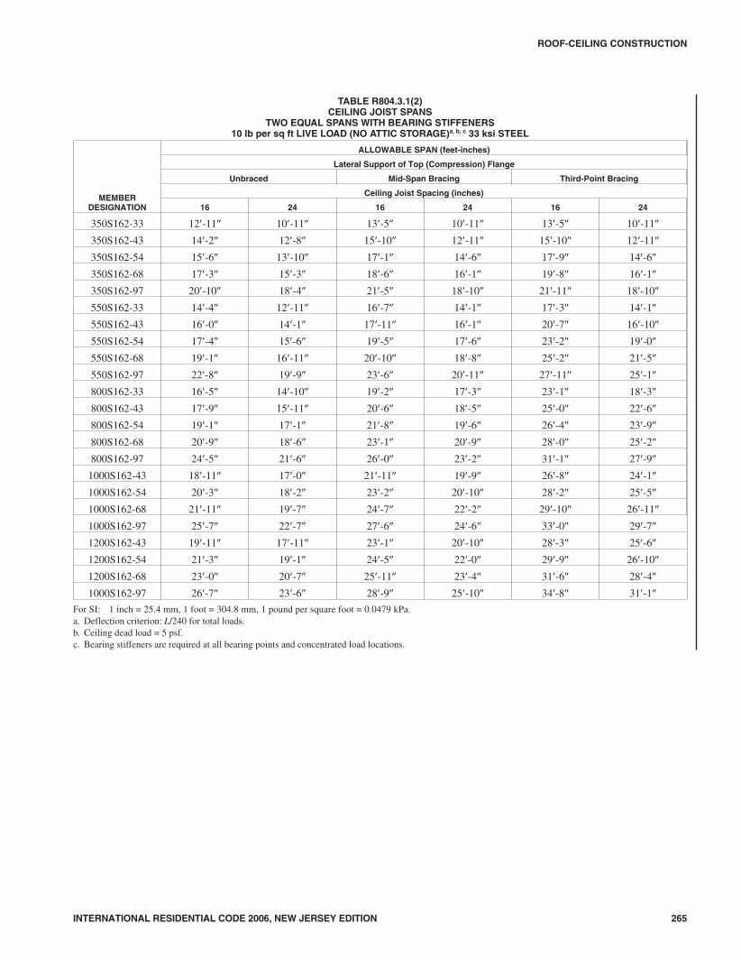
INTERNATIONAL RESIDENTIAL CODE 2006, NEW JERSEY EDITION 265
ROOF-CEILING CONSTRUCTION
TABLE R804.3.1(2)CEILING JOIST SPANS
TWO EQUAL SPANS WITH BEARING STIFFENERS10 lb per sq ft LIVE LOAD (NO ATTIC STORAGE)a, b, c 33 ksi STEEL
MEMBERDESIGNATION
ALLOWABLE SPAN (feet-inches)
Lateral Support of Top (Compression) Flange
Unbraced Mid-Span Bracing Third-Point Bracing
Ceiling Joist Spacing (inches)
16 24 16 24 16 24
350S162-33 12�-11� 10�-11� 13�-5� 10�-11� 13�-5� 10�-11�
350S162-43 14�-2� 12�-8� 15�-10� 12�-11� 15�-10� 12�-11�
350S162-54 15�-6� 13�-10� 17�-1� 14�-6� 17�-9� 14�-6�
350S162-68 17�-3� 15�-3� 18�-6� 16�-1� 19�-8� 16�-1�
350S162-97 20�-10� 18�-4� 21�-5� 18�-10� 21�-11� 18�-10�
550S162-33 14�-4� 12�-11� 16�-7� 14�-1� 17�-3� 14�-1�
550S162-43 16�-0� 14�-1� 17�-11� 16�-1� 20�-7� 16�-10�
550S162-54 17�-4� 15�-6� 19�-5� 17�-6� 23�-2� 19�-0�
550S162-68 19�-1� 16�-11� 20�-10� 18�-8� 25�-2� 21�-5�
550S162-97 22�-8� 19�-9� 23�-6� 20�-11� 27�-11� 25�-1�
800S162-33 16�-5� 14�-10� 19�-2� 17�-3� 23�-1� 18�-3�
800S162-43 17�-9� 15�-11� 20�-6� 18�-5� 25�-0� 22�-6�
800S162-54 19�-1� 17�-1� 21�-8� 19�-6� 26�-4� 23�-9�
800S162-68 20�-9� 18�-6� 23�-1� 20�-9� 28�-0� 25�-2�
800S162-97 24�-5� 21�-6� 26�-0� 23�-2� 31�-1� 27�-9�
1000S162-43 18�-11� 17�-0� 21�-11� 19�-9� 26�-8� 24�-1�
1000S162-54 20�-3� 18�-2� 23�-2� 20�-10� 28�-2� 25�-5�
1000S162-68 21�-11� 19�-7� 24�-7� 22�-2� 29�-10� 26�-11�
1000S162-97 25�-7� 22�-7� 27�-6� 24�-6� 33�-0� 29�-7�
1200S162-43 19�-11� 17�-11� 23�-1� 20�-10� 28�-3� 25�-6�
1200S162-54 21�-3� 19�-1� 24�-5� 22�-0� 29�-9� 26�-10�
1200S162-68 23�-0� 20�-7� 25�-11� 23�-4� 31�-6� 28�-4�
1000S162-97 26�-7� 23�-6� 28�-9� 25�-10� 34�-8� 31�-1�
For SI: 1 inch = 25.4 mm, 1 foot = 304.8 mm, 1 pound per square foot = 0.0479 kPa.a. Deflection criterion: L/240 for total loads.b. Ceiling dead load = 5 psf.c. Bearing stiffeners are required at all bearing points and concentrated load locations.
3108_NJ_Res_2006.prnM:\data\CODES\STATE CODES\New Jersey\2006\NJ_Res_2006\Final VP_Chgo\08_NJ_Res_2006.vpTuesday, April 17, 2007 11:32:32 AM
Color profile: Generic CMYK printer profileComposite Default screen

266 INTERNATIONAL RESIDENTIAL CODE 2006, NEW JERSEY EDITION
ROOF-CEILING CONSTRUCTION
TABLE R804.3.1(3)CEILING JOIST SPANS
SINGLE SPANS WITH BEARING STIFFENERS20 lb per sq ft LIVE LOAD (LIMITED ATTIC STORAGE)a, b, c 33 ksi STEEL
MEMBERDESIGNATION
ALLOWABLE SPAN (feet-inches)
Lateral Support of Top (Compression) Flange
Unbraced Mid-Span Bracing Third-Point Bracing
Ceiling Joist Spacing (inches)
16 24 16 24 16 24
350S162-33 8�-2� 7�-2� 9�-9� 8�-1� 9�-11� 8�-1�
350S162-43 8�-10� 7�-10� 11�-0� 9�-5� 11�-0� 9�-7�
350S162-54 9�-6� 8�-6� 11�-9� 10�-3� 11�-9� 10�-3�
350S162-68 10�-4� 9�-2� 12�-7� 11�-0� 12�-7� 11�-0�
350S162-97 12�-1� 10�-8� 14�-0� 12�-0� 14�-0� 12�-0�
550S162-33 9�-2� 8�-3� 12�-2� 10�-2� 12�-6� 10�-5�
550S162-43 10�-1� 9�-1� 13�-7� 11�-7� 14�-5� 12�-2�
550S162-54 10�-9� 9�-8� 14�-10� 12�-10� 15�-11� 13�-6�
550S162-68 11�-7� 10�-4� 16�-4� 14�-0� 17�-5� 14�-11�
550S162-97 13�-4� 11�-10� 18�-5� 16�-2� 20�-1� 17�-1�
800S162-33 10�-7� 9�-6� 15�-1� 13�-0� 16�-2� 13�-7�
800S162-43 11�-4� 10�-2� 16�-5� 14�-6� 18�-2� 15�-9�
800S162-54 12�-0� 10�-9� 17�-4� 15�-6� 19�-6� 17�-0�
800S162-68 12�-10� 11�-6� 18�-5� 16�-6� 20�-10� 18�-3�
800S162-97 14�-7� 12�-11� 20�-5� 18�-3� 22�-11� 20�-5�
1000S162-43 12�-1� 10�-11� 17�-7� 15�-10� 19�-11� 17�-3�
1000S162-54 12�-10� 11�-6� 18�-7� 16�-9� 21�-2� 18�-10�
1000S162-68 13�-8� 12�-3� 19�-8� 17�-8� 22�-4� 20�-1�
1000S162-97 15�-4� 13�-8� 21�-8� 19�-5� 24�-5� 21�-11�
1200S162-43 12�-9� 11�-6� 18�-7� 16�-6� 20�-9� 18�-2�
1200S162-54 13�-6� 12�-2� 19�-7� 17�-8� 22�-5� 20�-2�
1200S162-68 14�-4� 12�-11� 20�-9� 18�-8� 23�-7� 21�-3�
1000S162-97 16�-1� 14�-4� 22�-10� 20�-6� 25�-9� 23�-2�
For SI: 1 inch = 25.4 mm, 1 foot = 304.8 mm, 1 pound per square foot = 0.0479 kPa.a. Deflection criterion: L/240 for total loads.b. Ceiling dead load = 5 psf.c. Bearing stiffeners are required at all bearing points and concentrated load locations.
3208_NJ_Res_2006.prnM:\data\CODES\STATE CODES\New Jersey\2006\NJ_Res_2006\Final VP_Chgo\08_NJ_Res_2006.vpTuesday, April 17, 2007 11:32:32 AM
Color profile: Generic CMYK printer profileComposite Default screen

INTERNATIONAL RESIDENTIAL CODE 2006, NEW JERSEY EDITION 267
ROOF-CEILING CONSTRUCTION
TABLE R804.3.1(4)CEILING JOIST SPANS
TWO EQUAL SPANS WITH BEARING STIFFENERS20 lb per sq ft LIVE LOAD (LIMITED ATTIC STORAGE)a, b, c 33 ksi STEEL
MEMBERDESIGNATION
ALLOWABLE SPAN (feet-inches)
Lateral Support of Top (Compression) Flange
Unbraced Mid-Span Bracing Third-Point Bracing
Ceiling Joist Spacing (inches)
16 24 16 24 16 24
350S162-33 10�-2� 8�-4� 10�-2� 8�-4� 10�-2� 8�-4�
350S162-43 12�-1� 9�-10� 12�-1� 9�-10� 12�-1� 9�-10�
350S162-54 13�-3� 11�-0� 13�-6� 11�-0� 13�-6� 11�-0�
350S162-68 14�-7� 12�-3� 15�-0� 12�-3� 15�-0� 12�-3�
350S162-97 17�-6� 14�-3� 17�-6� 14�-3� 17�-6� 14�-3�
550S162-33 12�-5� 10�-9� 13�-2� 10�-9� 13�-2� 10�-9�
550S162-43 13�-7� 12�-1� 15�-6� 12�-9� 15�-8� 12�-9�
550S162-54 14�-11� 13�-4� 16�-10� 14�-5� 17�-9� 14�-5�
550S162-68 16�-3� 14�-5� 18�-0� 16�-1� 20�-0� 16�-4�
550S162-97 19�-1� 16�-10� 20�-3� 18�-0� 23�-10� 19�-5�
800S162-33 14�-3� 12�-4� 16�-7� 12�-4� 16�-7� 12�-4�
800S162-43 15�-4� 13�-10� 17�-9� 16�-0� 21�-8� 17�-9�
800S162-54 16�-5� 14�-9� 18�-10� 16�-11� 22�-11� 20�-6�
800S162-68 17�-9� 15�-11� 20�-0� 18�-0� 24�-3� 21�-10�
800S162-97 20�-8� 18�-3� 22�-3� 19�-11� 26�-9� 24�-0�
1000S162-43 16�-5� 14�-9� 19�-0� 17�-2� 23�-3� 18�-11�
1000S162-54 17�-6� 15�-8� 20�-1� 18�-1� 24�-6� 22�-1�
1000S162-68 18�-10� 16�-10� 21�-4� 19�-2� 25�-11� 23�-4�
1000S162-97 21�-8� 19�-3� 23�-7� 21�-2� 28�-5� 25�-6�
1200S162-43 17�-3� 15�-7� 20�-1� 18�-2� 24�-6� 18�-3�
1200S162-54 18�-5� 16�-6� 21�-3� 19�-2� 25�-11� 23�-5�
1200S162-68 19�-9� 17�-8� 22�-6� 20�-3� 27�-4� 24�-8�
1000S162-97 22�-7� 20�-1� 24�-10� 22�-3� 29�-11� 26�-11�
For SI: 1 inch = 25.4 mm, 1 foot = 304.8 mm, 1 pound per square foot = 0.0479 kPa.a. Deflection criterion: L/240 for total loads.b. Ceiling dead load = 5 psf.c. Bearing stiffeners are required at all bearing points and concentrated load locations.
3308_NJ_Res_2006.prnM:\data\CODES\STATE CODES\New Jersey\2006\NJ_Res_2006\Final VP_Chgo\08_NJ_Res_2006.vpTuesday, April 17, 2007 11:32:33 AM
Color profile: Generic CMYK printer profileComposite Default screen

268 INTERNATIONAL RESIDENTIAL CODE 2006, NEW JERSEY EDITION
ROOF-CEILING CONSTRUCTION
TABLE R804.3.1(5)CEILING JOIST SPANS
SINGLE SPANS WITHOUT BEARING STIFFENERS10 lb per sq ft LIVE LOAD (NO ATTIC STORAGE)a, b 33 ksi STEEL
MEMBERDESIGNATION
ALLOWABLE SPAN (feet-inches)
Lateral Support of Top (Compression) Flange
Unbraced Mid-Span Bracing Third-Point Bracing
Ceiling Joist Spacing (inches)
16 24 16 24 16 24
350S162-33 9�-5� 8�-6� 12�-2� 10�-4� 12�-2� 10�-7�
350S162-43 10�-3� 9�-12� 13�-2� 11�-6� 13�-2� 11�-6�
350S162-54 11�-1� 9�-11� 13�-9� 12�-0� 13�-9� 12�-0�
350S162-68 12�-1� 10�-9� 14�-8� 12�-10� 14�-8� 12�-10�
350S162-97 14�-4� 12�-7� 16�-10� 14�-3� 16�-4� 14�-3�
550S162-33 10�-7� 9�-6� 14�-10� 12�-10� 15�-11� 13�-4�
550S162-43 11�-8� 10�-6� 16�-4� 14�-3� 17�-10� 15�-3�
550S162-54 12�-6� 11�-2� 17�-7� 15�-7� 19�-5� 16�-10�
550S162-68 13�-6� 12�-1� 19�-2� 17�-0� 21�-0� 18�-4�
550S162-97 15�-9� 13�-11� 21�-8� 19�-3� 23�-5� 20�-5�
800S162-33 — — — — — —
800S162-43 13�-0� 11�-9� 18�-10� 17�-0� 21�-6� 19�-0�
800S162-54 13�-10� 12�-5� 20�-0� 18�-0� 22�-9� 20�-4�
800S162-68 14�-11� 13�-4� 21�-3� 19�-1� 24�-1� 21�-8�
800S162-97 17�-1� 15�-2� 23�-10� 21�-3� 26�-7� 23�-10�
1000S162-43 — — — — — —
1000S162-54 14�-9� 13�-3� 21�-4� 19�-3� 24�-4� 22�-0�
1000S162-68 15�-10� 14�-2� 22�-8� 20�-5� 25�-9� 23�-2�
1000S162-97 18�-0� 16�-0� 25�-3� 22�-7� 28�-3� 25�-4�
1200S162-43 — — — — — —
1200S162-54 — — — — — —
1200S162-68 16�-8� 14�-11� 23�-11� 21�-6� 27�-2� 24�-6�
1000S162-97 18�-9� 16�-9� 26�-6� 23�-8� 29�-9� 26�-9�
For SI: 1 inch = 25.4 mm, 1 foot = 304.8 mm, 1 pound per square foot = 0.0479 kPa.a. Deflection criterion: L/240 for total loads.b. Ceiling dead load = 5 psf.
3408_NJ_Res_2006.prnM:\data\CODES\STATE CODES\New Jersey\2006\NJ_Res_2006\Final VP_Chgo\08_NJ_Res_2006.vpTuesday, April 17, 2007 11:32:33 AM
Color profile: Generic CMYK printer profileComposite Default screen
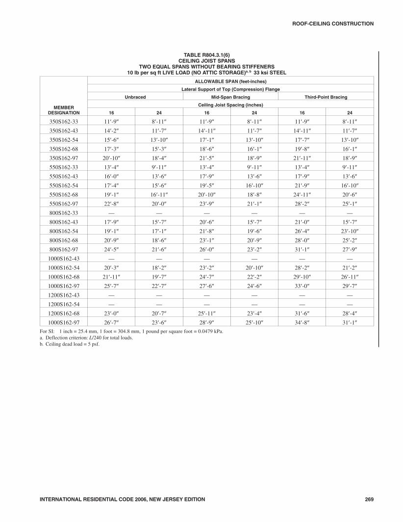
INTERNATIONAL RESIDENTIAL CODE 2006, NEW JERSEY EDITION 269
ROOF-CEILING CONSTRUCTION
TABLE R804.3.1(6)CEILING JOIST SPANS
TWO EQUAL SPANS WITHOUT BEARING STIFFENERS10 lb per sq ft LIVE LOAD (NO ATTIC STORAGE)a, b 33 ksi STEEL
MEMBERDESIGNATION
ALLOWABLE SPAN (feet-inches)
Lateral Support of Top (Compression) Flange
Unbraced Mid-Span Bracing Third-Point Bracing
Ceiling Joist Spacing (inches)
16 24 16 24 16 24
350S162-33 11�-9� 8�-11� 11�-9� 8�-11� 11�-9� 8�-11�
350S162-43 14�-2� 11�-7� 14�-11� 11�-7� 14�-11� 11�-7�
350S162-54 15�-6� 13�-10� 17�-1� 13�-10� 17�-7� 13�-10�
350S162-68 17�-3� 15�-3� 18�-6� 16�-1� 19�-8� 16�-1�
350S162-97 20�-10� 18�-4� 21�-5� 18�-9� 21�-11� 18�-9�
550S162-33 13�-4� 9�-11� 13�-4� 9�-11� 13�-4� 9�-11�
550S162-43 16�-0� 13�-6� 17�-9� 13�-6� 17�-9� 13�-6�
550S162-54 17�-4� 15�-6� 19�-5� 16�-10� 21�-9� 16�-10�
550S162-68 19�-1� 16�-11� 20�-10� 18�-8� 24�-11� 20�-6�
550S162-97 22�-8� 20�-0� 23�-9� 21�-1� 28�-2� 25�-1�
800S162-33 — — — — — —
800S162-43 17�-9� 15�-7� 20�-6� 15�-7� 21�-0� 15�-7�
800S162-54 19�-1� 17�-1� 21�-8� 19�-6� 26�-4� 23�-10�
800S162-68 20�-9� 18�-6� 23�-1� 20�-9� 28�-0� 25�-2�
800S162-97 24�-5� 21�-6� 26�-0� 23�-2� 31�-1� 27�-9�
1000S162-43 — — — — — —
1000S162-54 20�-3� 18�-2� 23�-2� 20�-10� 28�-2� 21�-2�
1000S162-68 21�-11� 19�-7� 24�-7� 22�-2� 29�-10� 26�-11�
1000S162-97 25�-7� 22�-7� 27�-6� 24�-6� 33�-0� 29�-7�
1200S162-43 — — — — — —
1200S162-54 — — — — — —
1200S162-68 23�-0� 20�-7� 25�-11� 23�-4� 31�-6� 28�-4�
1000S162-97 26�-7� 23�-6� 28�-9� 25�-10� 34�-8� 31�-1�
For SI: 1 inch = 25.4 mm, 1 foot = 304.8 mm, 1 pound per square foot = 0.0479 kPa.a. Deflection criterion: L/240 for total loads.b. Ceiling dead load = 5 psf.
3508_NJ_Res_2006.prnM:\data\CODES\STATE CODES\New Jersey\2006\NJ_Res_2006\Final VP_Chgo\08_NJ_Res_2006.vpTuesday, April 17, 2007 11:32:33 AM
Color profile: Generic CMYK printer profileComposite Default screen

270 INTERNATIONAL RESIDENTIAL CODE 2006, NEW JERSEY EDITION
ROOF-CEILING CONSTRUCTION
TABLE R804.3.1(7)CEILING JOIST SPANS
SINGLE SPANS WITHOUT BEARING STIFFENERS20 lb per sq ft LIVE LOAD (LIMITED ATTIC STORAGE)a, b 33 ksi STEEL
MEMBERDESIGNATION
ALLOWABLE SPAN (feet-inches)
Lateral Support of Top (Compression) Flange
Unbraced Mid-Span Bracing Third-Point Bracing
Ceiling Joist Spacing (inches)
16 24 16 24 16 24
350S162-33 8�-2� 6�-10� 9�-9� 6�-10� 9�-11� 6�-10�
350S162-43 8�-10� 7�-10� 11�-0� 9�-5� 11�-0� 9�-7�
350S162-54 9�-6� 8�-6� 11�-9� 10�-3� 11�-9� 10�-3�
350S162-68 10�-4� 9�-2� 12�-7� 11�-0� 12�-7� 11�-0�
350S162-97 12�-10� 10�-8� 13�-9� 12�-0� 13�-9� 12�-0�
550S162-33 9�-2� 8�-3� 12�-2� 8�-5� 12�-6� 8�-5�
550S162-43 10�-1� 9�-1� 13�-7� 11�-8� 14�-5� 12�-2�
550S162-54 10�-9� 9�-8� 14�-10� 12�-10� 15�-11� 13�-6�
550S162-68 11�-7� 10�-4� 16�-4� 14�-0� 17�-5� 14�-11�
550S162-97 13�-4� 11�-10� 18�-5� 16�-2� 20�-1� 17�-4�
800S162-33 — — — — — —
800S162-43 11�-4� 10�-1� 16�-5� 13�-6� 18�-1� 13�-6�
800S162-54 20�-0� 10�-9� 17�-4� 15�-6� 19�-6� 27�-0�
800S162-68 12�-10� 11�-6� 18�-5� 16�-6� 20�-10� 18�-3�
800S162-97 14�-7� 12�-11� 20�-5� 18�-3� 22�-11� 20�-5�
1000S162-43 — — — — — —
1000S162-54 12�-10� 11�-6� 18�-7� 16�-9� 21�-2� 15�-5�
1000S162-68 13�-8� 12�-3� 19�-8� 17�-8� 22�-4� 20�-1�
1000S162-97 15�-4� 13�-8� 21�-8� 19�-5� 24�-5� 21�-11�
1200S162-43 — — — — — —
1200S162-54 — — — — — —
1200S162-68 14�-4� 12�-11� 20�-9� 18�-8� 23�-7� 21�-3�
1000S162-97 16�-1� 14�-4� 22�-10� 20�-6� 25�-9� 23�-2�
For SI: 1 inch = 25.4 mm, 1 foot = 304.8 mm, 1 pound per square foot = 0.0479 kPa.a. Deflection criterion: L/240 for total loads.b. Ceiling dead load = 5 psf.
3608_NJ_Res_2006.prnM:\data\CODES\STATE CODES\New Jersey\2006\NJ_Res_2006\Final VP_Chgo\08_NJ_Res_2006.vpTuesday, April 17, 2007 11:32:33 AM
Color profile: Generic CMYK printer profileComposite Default screen

INTERNATIONAL RESIDENTIAL CODE 2006, NEW JERSEY EDITION 271
ROOF-CEILING CONSTRUCTION
TABLE R804.3.1(8)CEILING JOIST SPANS
TWO EQUAL SPANS WITHOUT BEARING STIFFENERS20 lb per sq ft LIVE LOAD (LIMITED ATTIC STORAGE)a, b 33 ksi STEEL
MEMBERDESIGNATION
ALLOWABLE SPAN (feet-inches)
Lateral Support of Top (Compression) Flange
Unbraced Mid-Span Bracing Third-Point Bracing
Ceiling Joist Spacing (inches)
16 24 16 24 16 24
350S162-33 8�-1� 6�-1� 8�-1� 6�-1� 8�-1� 6�-1�
350S162-43 10�-7� 8�-1� 10�-7� 8�-1� 10�-7� 8�-1�
350S162-54 12�-8� 9�-10� 12�-8� 9�-10� 12�-8� 9�-10�
350S162-68 14�-7� 11�-10� 14�-11� 11�-10� 14�-11� 11�-10�
350S162-97 17�-6� 14�-3� 17�-6� 14�-3� 17�-6� 14�-3�
550S162-33 8�-11� 6�-8� 8�-11� 6�-8� 8�-11� 6�-8�
550S162-43 12�-3� 9�-2� 12�-3� 9�-2� 12�-3� 9�-2�
550S162-54 14�-11� 11�-8� 15�-4� 11�-8� 15�-4� 11�-8�
550S162-68 16�-3� 14�-5� 18�-0� 15�-8� 18�-10� 14�-7�
550S162-97 19�-1� 16�-10� 20�-3� 18�-0� 23�-9� 19�-5�
800S162-33 — — — — — —
800S162-43 13�-11� 9�-10� 13�-11� 9�-10� 13�-11� 9�-10�
800S162-54 16�-5� 13�-9� 18�-8� 13�-9� 18�-8� 13�-9�
800S162-68 17�-9� 15�-11� 20�-0� 18�-0� 24�-1� 18�-3�
800S162-97 20�-8� 18�-3� 22�-3� 19�-11� 26�-9� 24�-0�
1000S162-43 — — — — — —
1000S162-54 17�-6� 13�-11� 19�-1� 13�-11� 19�-1� 13�-11�
1000S162-68 18�-10� 16�-10� 21�-4� 19�-2� 25�-11� 19�-7�
1000S162-97 21�-8� 19�-3� 23�-7� 21�-2� 28�-5� 25�-6�
1200S162-43 — — — — — —
1200S162-54 — — — — — —
1200S162-68 19�-9� 17�-8� 22�-6� 19�-8� 26�-8� 19�-8�
1000S162-97 22�-7� 20�-1� 24�-10� 22�-3� 29�-11� 26�-11�
For SI: 1 inch = 25.4 mm, 1 foot = 304.8 mm, 1 pound per square foot = 0.0479 kPa.a. Deflection criterion: L/240 for total loads.b. Ceiling dead load = 5 psf.
3708_NJ_Res_2006.prnM:\data\CODES\STATE CODES\New Jersey\2006\NJ_Res_2006\Final VP_Chgo\08_NJ_Res_2006.vpTuesday, April 17, 2007 11:32:33 AM
Color profile: Generic CMYK printer profileComposite Default screen

272 INTERNATIONAL RESIDENTIAL CODE 2006, NEW JERSEY EDITION
ROOF-CEILING CONSTRUCTION
TABLE R804.3.1NUMBER OF SCREWS REQUIRED FOR CEILING JOIST TO RAFTER CONNECTIONa
ROOFSLOPE
NUMBER OF SCREWS
Building width (feet)
24 28 32 36 40
Ground snow load (psf)
20 30 50 70 20 30 50 70 20 30 50 70 20 30 50 70 20 30 50 70
3/12 5 6 9 11 5 7 10 13 6 8 11 15 7 8 13 17 8 9 14 19
4/12 4 5 7 9 4 5 8 10 5 6 9 12 5 7 10 13 6 7 11 14
5/12 3 4 6 7 4 4 6 8 4 5 7 10 5 5 8 11 5 6 9 12
6/12 3 3 5 6 3 4 6 7 4 4 6 8 4 5 7 9 4 5 8 10
7/12 3 3 4 6 3 3 5 7 3 4 6 7 4 4 6 8 4 5 7 9
8/12 2 3 4 5 3 3 5 6 3 4 5 7 3 4 6 8 4 4 6 8
9/12 2 3 4 5 3 3 4 6 3 3 5 6 3 4 5 7 3 4 6 8
10/12 2 2 4 5 2 3 4 5 3 3 5 6 3 3 5 7 3 4 6 7
11/12 2 2 3 4 2 3 4 5 3 3 4 6 3 3 5 6 3 4 5 7
12/12 2 2 3 4 2 3 4 5 2 3 4 5 3 3 5 6 3 4 5 7
For SI: 1 inch = 25.4 mm, 1 foot = 304.8 mm, 1 pound per square foot = 0.0479 kPa.a. Screws shall be No. 10.
For SI: 1 mil = 0.0254 mm.
FIGURE R804.3.1(1)JOIST TO RAFTER CONNECTION
3808_NJ_Res_2006.prnM:\data\CODES\STATE CODES\New Jersey\2006\NJ_Res_2006\Final VP_Chgo\08_NJ_Res_2006.vpTuesday, April 17, 2007 11:32:34 AM
Color profile: Generic CMYK printer profileComposite Default screen

R804.3.2 Ceiling joist bracing. The bottom flanges of steelceiling joists shall be laterally braced in accordance with Sec-tion R702. The top flanges of steel ceiling joists shall be later-ally braced with a minimum of 33 mil (0.84 mm) C-section,33 mil (0.84 mm) track section or 11/2 inch by 33 mil (38 mmby 0.84 mm) continuous steel strapping as required in TablesR804.3.1(1) through R804.3.1(8). Lateral bracing shall beinstalled in accordance with Figure R804.3. C-section, tracksor straps shall be fastened to the top flange at each joist with atleast one No. 8 screw and shall be fastened to blocking with atleast two No. 8 screws. Blocking or bridging (X-bracing)shall be installed between joists in line with strap bracing at amaximum spacing of 12 feet (3658 mm) measured perpen-dicular to the joists, and at the termination of all straps. Thethird-point bracing span values from Tables R804.3.1(1)through R804.3.1(8) shall be used for straps installed atcloser spacings than third-point bracing, or when sheathing isapplied to the top of the ceiling joists.
R804.3.3 Allowable rafter spans. The horizontal projec-tion of the rafter span, as shown in Figure R804.3, shall notexceed the limits set forth in Table R804.3.3(1). Windspeeds shall be converted to equivalent ground snow loadsin accordance with Table R804.3.3(2). Rafter spans shall beselected based on the higher of the ground snow load or theequivalent snow load converted from the wind speed. Whenrequired, a rafter support brace shall be a minimum of350S162-33 C-section with maximum length of 8 feet(2438 mm) and shall be connected to a ceiling joist and raf-ter with four No. 10 screws at each end.
R804.3.3.1 Rafter framing. Rafters shall be connectedto a parallel ceiling joist to form a continuous tiebetween exterior walls in accordance with FiguresR804.3 and R804.3.1(1) and Table R804.3.1. Raftersshall be connected to a ridge member with a minimum2-inch by 2-inch (51 mm by 51 mm) clip angle fastenedwith minimum No. 10 screws to the ridge member inaccordance with Figure R804.3.3.1 and TableR804.3.3.1. The clip angle shall have a minimum steelthickness as the rafter member and shall extend the fulldepth of the rafter member. The ridge member shall befabricated from a C-section and a track section, whichshall be of a minimum size and steel thickness as theadjacent rafters and shall be installed in accordancewith Figure R804.3.3.1.
R804.3.3.2 Roof cantilevers. Roof cantilevers shall notexceed 24 inches (610 mm) in accordance with FigureR804.3. Roof cantilevers shall be supported by a headerin accordance with Section R603.6 or shall be supportedby the floor framing in accordance with SectionR505.3.7.
R804.3.4 Rafter bottom flange bracing. The bottomflanges of steel rafters shall be continuously braced with aminimum 33-mil (0.84 mm) C-section, 33-mil (0.84 mm)track section, or a 11/2-inch by 33-mil (38 mm by 0.84 mm)steel strapping at a maximum spacing of 8 feet (2438 mm)as measured parallel to the rafters. Bracing shall be installedin accordance with Figure R804.3. The C-section, track sec-tion, or straps shall be fastened to blocking with at least twoNo. 8 screws. Blocking or bridging (X-bracing) shall be
installed between rafters in-line with the continuous bracingat a maximum spacing of 12 feet (3658 mm) measured per-pendicular to the rafters and at the termination of all straps.The ends of continuous bracing shall be fastened to block-ing with at least two No. 8 screws.
R804.3.5 Cutting and notching. Flanges and lips of load-bearing steel roof framing members shall not be cut or notched.Holes in webs shall be in accordance with Section R804.2.
R804.3.6 Hole patching. Web holes not conforming to therequirements in Section R804.2 shall be designed in accor-dance with one of the following:
1. Framing members shall be replaced or designed inaccordance with accepted engineering practices whenweb holes exceed the following size limits:
1.1. The depth of the hole, measured across theweb, exceeds 70 percent of the flat width ofthe web; or,
1.2. The length of the hole, measured along theweb, exceeds 10 inches (254 mm) or the depthof the web, whichever is greater.
2. Web holes not exceeding the dimensional require-ments in Section R804.3.6, Item 1 shall be patchedwith a solid steel plate, stud section, or track section inaccordance with Figure R804.3.6. The steel patchshall be of a minimum thickness as the receivingmember and shall extend at least 1 inch (25 mm)beyond all edges of the hole. The steel patch shall befastened to the web of the receiving member with No.8 screws spaced no greater than 1 inch (25 mm) cen-ter-to-center along the edges of the patch with mini-mum edge distance of 1/2 inch (13 mm).
R804.3.7 Splicing. Rafters and other structural members,except ceiling joists, shall not be spliced. Splices in ceilingjoists shall only be permitted at interior bearing points andshall be constructed in accordance with Figure R804.3.7(1).Spliced ceiling joists shall be connected with the same num-ber and size of screws on connection. Splicing of tracksshall conform to Figure R804.3.7(2).
R804.3.8 Bearing stiffener. A bearing stiffener shall befabricated from a minimum 33-mil (0.84 mm) C-section ortrack section. Each stiffener shall be fastened to the web ofthe ceiling joist with a minimum of four No. 8 screwsequally spaced as shown in Figure R804.3.8. Stiffeners shallextend across the full depth of the web and shall be installedon either side of the web.
R804.3.9 Headers. Roof-ceiling framing above wall open-ings shall be supported on headers. The allowable spans forheaders in bearing walls shall not exceed the values set forthin Table R603.6(1).
R804.3.10 Framing of opening. Openings in roof and ceil-ing framing shall be framed with headers and trimmersbetween ceiling joists or rafters. Header joist spans shall notexceed 4 feet (1219 mm). Header and trimmer joists shall befabricated from joist and track sections, which shall be of aminimum size and thickness in accordance with FiguresR804.3.10(1) and R804.3.10(2). Each header joist shall be
INTERNATIONAL RESIDENTIAL CODE 2006, NEW JERSEY EDITION 273
ROOF-CEILING CONSTRUCTION
3908_NJ_Res_2006.prnM:\data\CODES\STATE CODES\New Jersey\2006\NJ_Res_2006\Final VP_Chgo\08_NJ_Res_2006.vpTuesday, April 17, 2007 11:32:34 AM
Color profile: Generic CMYK printer profileComposite Default screen

connected to a trimmer joist with a minimum of four 2-inchby 2-inch (51 by 51 mm) clip angles. Each clip angle shall befastened to both the header and trimmer joists with four No. 8screws, evenly spaced, through each leg of the clip angle. Theclip angles shall have a steel thickness not less than that of thefloor joist.
R804.4 Roof tie-down. Roof assemblies subject to wind upliftpressures of 20 pounds per square foot (0.96 kN/m2) or greater,as established in Table R301.2(2), shall have rafter-to-bearingwall ties provided in accordance with Table R802.11.
274 INTERNATIONAL RESIDENTIAL CODE 2006, NEW JERSEY EDITION
ROOF-CEILING CONSTRUCTION
TABLE R804.3.3(1)ALLOWABLE HORIZONTAL RAFTER SPANSa, b, c 33 ksi STEEL
MEMBERDESIGNATION
ALLOWABLE SPAN MEASURED HORIZONTALLY (feet-inches)
Ground Snow Load
20 psf 30 psf 50 psf 70 psf
Rafter spacing (in)
16 24 16 24 16 24 16 24
550S162-33 14�-0� 11�-5� 11�-10� 9�-8� 9�-5� 7�-8� 8�-1� 6�-7�
550S162-43 16�-6� 13�-10� 14�-4� 11�-9� 11�-5� 9�-4� 9�-10� 8�-0�
550S162-54 17�-9� 15�-6� 15�-6� 13�-2� 12�-11� 10�-6� 11�-1� 9�-0�
550S162-68 19�-0� 16�-7� 16�-8� 14�-7� 14�-1� 11�-10� 12�-5� 10�-2�
550S162-97 21�-2� 18�-6� 18�-7� 16�-2� 15�-8� 13�-8� 14�-0� 12�-2�
800S162-33 17�-0� 13�-11� 14�-5� 11�-9� 11�-6� 7�-9� 8�-6� 5�-8�
800S162-43 21�-1� 17�-3� 17�-10� 14�-7� 14�-3� 11�-7� 12�-2� 9�-11�
800S162-54 23�-11� 20�-4� 21�-0� 17�-3� 16�-10� 13�-9� 14�-5� 11�-9�
800S162-68 25�-9� 22�-6� 22�-7� 19�-5� 19�-0� 15�-6� 16�-3� 13�-3�
800S162-97 28�-9� 25�-1� 25�-2� 22�-0� 21�-3� 18�-7� 19�-0� 16�-0�
1000S162-43 23�-4� 19�-1� 19�-9� 16�-2� 15�-9� 12�-11� 13�-6� 10�-0�
1000S162-54 27�-8� 22�-7� 23�-5� 19�-1� 18�-8� 15�-3� 16�-0� 13�-1�
1000S162-68 30�-11� 27�-0� 27�-2� 22�-11� 22�-5� 18�-3� 19�-2� 15�-8�
1000S162-97 34�-7� 30�-2� 30�-4� 26�-6� 25�-7� 22�-1� 22�-10� 18�-11�
1200S162-43 25�-5� 20�-9� 21�-6� 17�-6� 17�-1� 11�-5� 12�-6� 8�-6�
1200S162-54 30�-0� 24�-6� 25�-5� 20�-9� 20�-3� 16�-7� 17�-5� 14�-2�
1200S162-68 35�-5� 28�-11� 30�-0� 24�-6� 23�-11� 19�-6� 20�-6� 16�-9�
1200S162-97 40�-4� 35�-3� 35�-5� 30�-11� 29�-10� 25�-5� 26�-8� 21�-9�
For SI: 1 inch = 25.4 mm, 1 foot = 304.8 mm, 1 pound per square foot = 0.0479 kPa.a. Table provides maximum horizontal rafter spans in feet and inches for slopes between 3:12 and 12:12.b. Deflection criterion: L/240 for live loads and L/180 for total loads.c. Roof dead load = 12 psf.
TABLE R804.3.3(2)BASIC WIND SPEED TO EQUIVALENT SNOW LOAD CONVERSION
BASIC WIND SPEEDAND EXPOSURE
EQUIVALENT GROUND SNOW LOAD (psf)
Roof slope
Exp. A/B Exp. C 3:12 4:12 5:12 6:12 7:12 8:12 9:12 10:12 11:12 12:12
85 mph — 20 20 20 20 20 20 30 30 30 30
100 mph 85 mph 20 20 20 20 30 30 30 30 50 50
110 mph 100 mph 20 20 20 20 30 50 50 50 50 50
— 110 mph 30 30 30 50 50 50 70 70 70 —
For SI: 1 mile per hour = 0.447 m/s, 1 pound per square foot = 0.0479 kN/m2.
4008_NJ_Res_2006.prnM:\data\CODES\STATE CODES\New Jersey\2006\NJ_Res_2006\Final VP_Chgo\08_NJ_Res_2006.vpTuesday, April 17, 2007 11:32:34 AM
Color profile: Generic CMYK printer profileComposite Default screen

INTERNATIONAL RESIDENTIAL CODE 2006, NEW JERSEY EDITION 275
ROOF-CEILING CONSTRUCTION
TABLE R804.3.3.1NUMBER OF SCREWS REQUIRED AT EACH LEG OF CLIPANGLE FOR RAFTER TO RIDGE MEMBER CONNECTIONa
BUILDING WIDTH(feet)
NUMBER OF SCREWS
Ground snow load (psf)
0 to 20 21 to 30 31 to 50 51 to 70
24 2 2 3 4
28 2 3 4 5
32 2 3 4 5
36 3 3 5 6
40 3 4 5 7
For SI: 1 inch = 25.4 mm, 1 foot = 304.8 mm, 1 pound per square foot = 0.0479 kPa.a. Screws shall be No. 10 minimum.
For SI: 1 inch = 25.4 mm.
FIGURE R804.3.3.1RIDGE BOARD CONNECTION
For SI: 1 inch = 25.4 mm.
FIGURE R804.3.6HOLE PATCHING
4108_NJ_Res_2006.prnM:\data\CODES\STATE CODES\New Jersey\2006\NJ_Res_2006\Final VP_Chgo\08_NJ_Res_2006.vpTuesday, April 17, 2007 11:32:35 AM
Color profile: Generic CMYK printer profileComposite Default screen
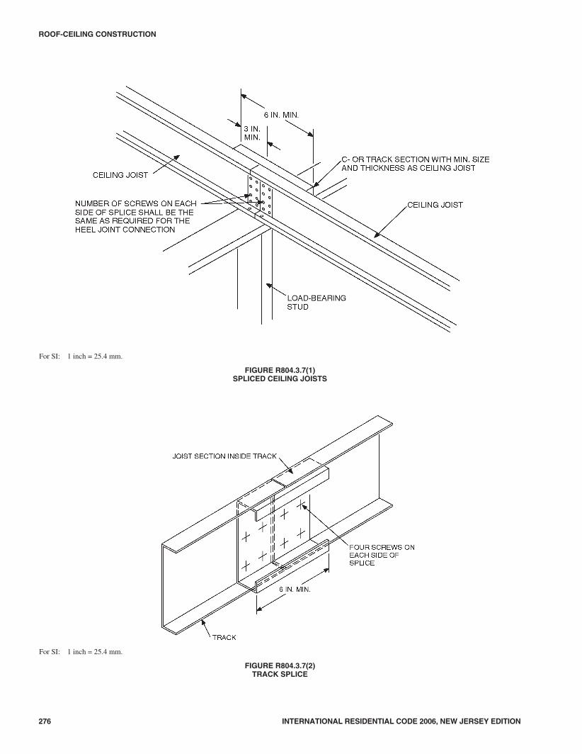
276 INTERNATIONAL RESIDENTIAL CODE 2006, NEW JERSEY EDITION
ROOF-CEILING CONSTRUCTION
For SI: 1 inch = 25.4 mm.
FIGURE R804.3.7(1)SPLICED CEILING JOISTS
For SI: 1 inch = 25.4 mm.
FIGURE R804.3.7(2)TRACK SPLICE
4208_NJ_Res_2006.prnM:\data\CODES\STATE CODES\New Jersey\2006\NJ_Res_2006\Final VP_Chgo\08_NJ_Res_2006.vpTuesday, April 17, 2007 11:32:35 AM
Color profile: Generic CMYK printer profileComposite Default screen

INTERNATIONAL RESIDENTIAL CODE 2006, NEW JERSEY EDITION 277
ROOF-CEILING CONSTRUCTION
FIGURE R804.3.8BEARING STIFFENER
For SI: 1 foot = 304.8 mm.
FIGURE R804.3.10(1)ROOF OPENING
4308_NJ_Res_2006.prnM:\data\CODES\STATE CODES\New Jersey\2006\NJ_Res_2006\Final VP_Chgo\08_NJ_Res_2006.vpTuesday, April 17, 2007 11:32:36 AM
Color profile: Generic CMYK printer profileComposite Default screen

SECTION R805CEILING FINISHES
R805.1 Ceiling installation. Ceilings shall be installed inaccordance with the requirements for interior wall finishes asprovided in Section R702.
SECTION R806ROOF VENTILATION
R806.1 Ventilation required. Enclosed attics and enclosedrafter spaces formed where ceilings are applied directly to theunderside of roof rafters shall have cross ventilation for eachseparate space by ventilating openings protected against theentrance of rain or snow. Ventilating openings shall be pro-vided with corrosion-resistant wire mesh, with 1/8 inch (3.2mm) minimum to 1/4 inch (6 mm) maximum openings.
R806.2 Minimum area. The total net free ventilating areashall not be less than 1/150 of the area of the space ventilatedexcept that reduction of the total area to 1/300 is permitted, pro-vided that at least 50 percent and not more than 80 percent ofthe required ventilating area is provided by ventilators locatedin the upper portion of the space to be ventilated at least 3 feet(914 mm) above the eave or cornice vents with the balance ofthe required ventilation provided by eave or cornice vents. Asan alternative, the net free cross-ventilation area may bereduced to 1/300 when a vapor barrier having a transmission ratenot exceeding 1 perm (5.7 � 10-11 kg/s � m2 � Pa) is installed onthe warm-in-winter side of the ceiling.
R806.3 Vent and insulation clearance. Where eave or cornicevents are installed, insulation shall not block the free flow of
air. A minimum of a 1-inch (25 mm) space shall be providedbetween the insulation and the roof sheathing and at the loca-tion of the vent.
R806.4 Conditioned attic assemblies. Unvented conditionedattic assemblies (spaces between the ceiling joists of the topstory and the roof rafters) are permitted under the followingconditions:
1. No interior vapor retarders are installed on the ceilingside (attic floor) of the unvented attic assembly.
2. An air-impermeable insulation is applied in direct con-tact to the underside/interior of the structural roof deck.“Air-impermeable” shall be defined by ASTM E 283.
3. Sufficient insulation is installed to maintain the monthlyaverage temperature of the condensing surface above45°F (7°C). The condensing surface is defined as eitherthe structural roof deck or the interior surface of anair-impermeable insulation applied in direct contact withthe underside/interior of the structural roof deck.“Air-impermeable” is quantitatively defined by ASTME 283. For calculation purposes, an interior temperatureof 68°F (20°C) is assumed. The exterior temperature isassumed to be the monthly average outside temperature.
SECTION R807ATTIC ACCESS
R807.1 Attic access. Buildings with combustible ceiling orroof construction shall have an attic access opening to atticareas that exceed 30 square feet (2.8 m2) and have a verticalheight of 30 inches (762 mm) or more.
278 INTERNATIONAL RESIDENTIAL CODE 2006, NEW JERSEY EDITION
ROOF-CEILING CONSTRUCTION
For SI: 1 inch = 25.4 mm.
FIGURE R804.3.10(2)HEADER TO TRIMMER CONNECTION
4408_NJ_Res_2006.prnM:\data\CODES\STATE CODES\New Jersey\2006\NJ_Res_2006\Final VP_Chgo\08_NJ_Res_2006.vpTuesday, April 17, 2007 11:32:36 AM
Color profile: Generic CMYK printer profileComposite Default screen

The rough-framed opening shall not be less than 22 inchesby 30 inches (559 mm by 762 mm) and shall be located in ahallway or other readily accessible location. A 30-inch (762mm) minimum unobstructed headroom in the attic space shallbe provided at some point above the access opening. See Sec-tion M1305.1.3 for access requirements where mechanicalequipment is located in attics.
SECTION R808INSULATION CLEARANCE
R808.1 Combustible insulation. Combustible insulation shallbe separated a minimum of 3 inches (76 mm) from recessedluminaires, fan motors and other heat-producing devices.
Exception: Where heat-producing devices are listed forlesser clearances, combustible insulation complying withthe listing requirements shall be separated in accordancewith the conditions stipulated in the listing.
Recessed luminaires installed in the building thermal enve-lope shall meet the requirements of the energy subcode(N.J.A.C. 5:23-3.18).
INTERNATIONAL RESIDENTIAL CODE 2006, NEW JERSEY EDITION 279
ROOF-CEILING CONSTRUCTION
4508_NJ_Res_2006.prnM:\data\CODES\STATE CODES\New Jersey\2006\NJ_Res_2006\Final VP_Chgo\08_NJ_Res_2006.vpTuesday, April 17, 2007 11:32:36 AM
Color profile: Generic CMYK printer profileComposite Default screen

280 INTERNATIONAL RESIDENTIAL CODE 2006, NEW JERSEY EDITION
4608_NJ_Res_2006.prnM:\data\CODES\STATE CODES\New Jersey\2006\NJ_Res_2006\Final VP_Chgo\08_NJ_Res_2006.vpTuesday, April 17, 2007 11:32:36 AM
Color profile: Generic CMYK printer profileComposite Default screen