chapter (8) retaining walls -...
TRANSCRIPT

Chapter (8) Retaining Walls

Page (177) Ahmed S. Al-Agha
Foundation Engineering Retaining Walls
Introduction Retaining walls must be designed for lateral earth pressure. The procedures of calculating lateral earth pressure was discussed previously in Chapter7. Different types of retaining walls are used to retain soil in different places. Three main types of retaining walls: 1. Gravity retaining wall (depends on its weight for resisting lateral earth force because it have a large weigh) 2. Semi-Gravity retaining wall (reduce the dimensions of the gravity retaining wall by using some reinforcement). 3. Cantilever retaining wall (reinforced concrete wall with small dimensions and it is the most economical type and the most common) Note: Structural design of cantilever retaining wall is depend on separating each part of wall and design it as a cantilever, so it’s called cantilever R.W.
The following figure shows theses different types of retaining walls:
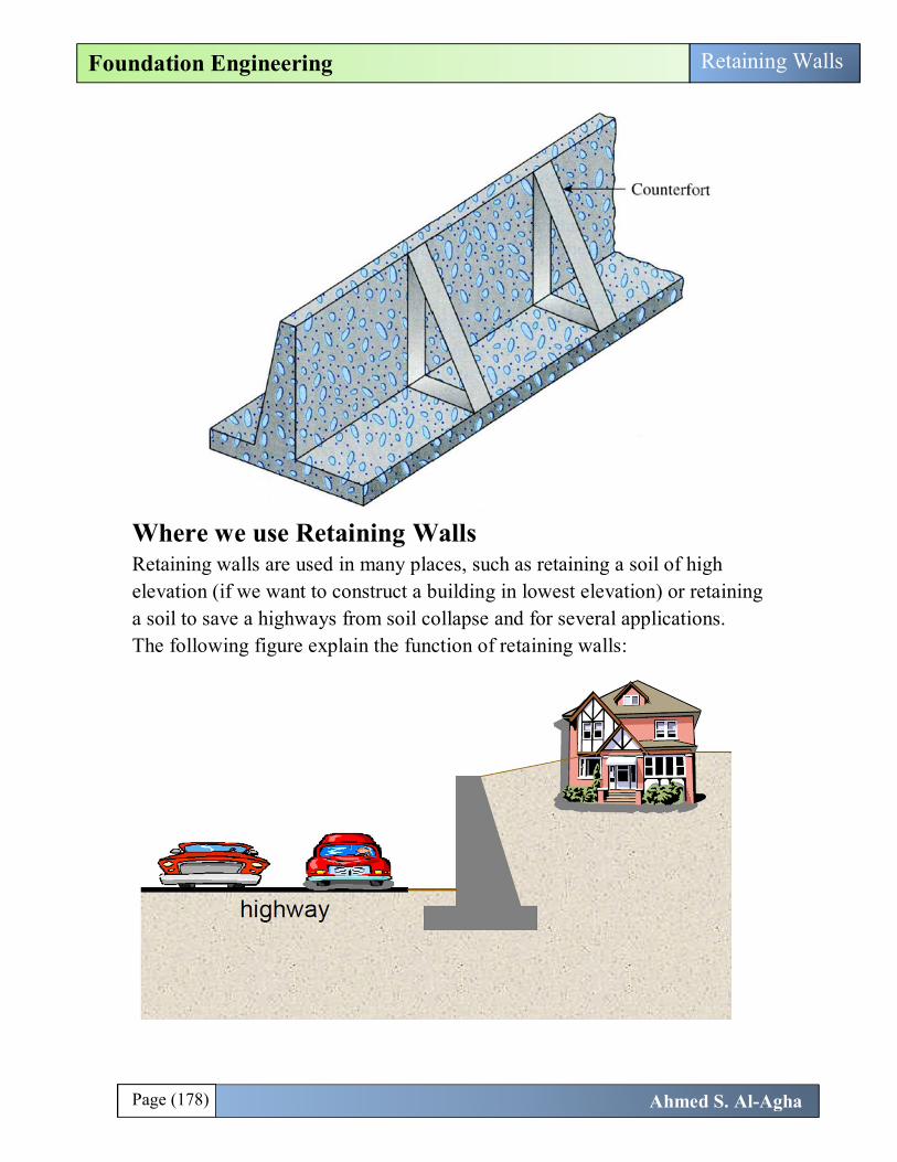
There are another type of retaining wall called “counterfort RW” and is a special type of cantilever RW used when the height of RW became larger than 6m, the moment applied on the wall will be large so we use spaced counterforts every a specified distance to reduce the moment RW.
Page (178) Ahmed S. Al-Agha
Foundation Engineering Retaining Walls
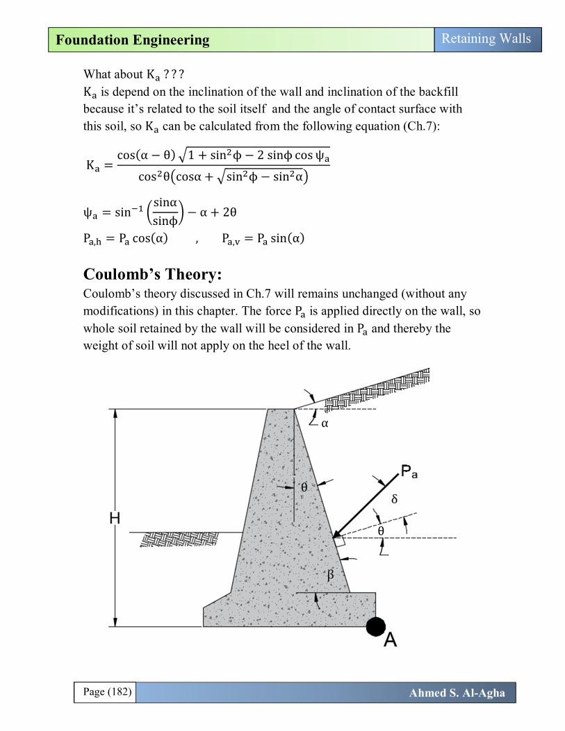
Where we use Retaining Walls Retaining walls are used in many places, such as retaining a soil of high elevation (if we want to construct a building in lowest elevation) or retaining a soil to save a highways from soil collapse and for several applications. The following figure explain the function of retaining walls:

Page (179) Ahmed S. Al-Agha
Foundation Engineering Retaining Walls
Elements of Retaining Walls Each retaining wall divided into three parts; stem, heel, and toe as shown for the following cantilever footing (as example):
Application of Lateral Earth Pressure Theories to Design Rankine Theory: Rankine theory discussed in Ch.7 was modified to be suitable for designing a retaining walls. This modification is drawing a vertical line from the lowest-right corner till intersection with the line of backfill, and then considering the force of soil acting on this vertical line. The soil between the wall and vertical line is not considered in the value of Pa, so we take this soil in consideration as a vertical weight applied on the stem of the retaining wall as will explained later.

Page (180) Ahmed S. Al-Agha
Foundation Engineering Retaining Walls
The following are all cases of rankine theory in designing a retaining wall: 1. The wall is vertical and backfill is horizontal:
Here the active force P is horizontal and can be calculated as following:
P =12
γH K , K = tan 45 −ϕ2
2. The wall is vertical and the backfill is inclined with horizontal by angle (훂):
γ, ϕ
γ, ϕ
α
α

Page (181) Ahmed S. Al-Agha
Foundation Engineering Retaining Walls
Here the active force P is inclined with angle (α) and can be calculated as following:
P =12
γH K
Why H ? → Because the pressure is applied on the vertical line (according active theory) not on the wall, so we need the height of this vertical line H H = H + d →→ d = L tanα K is calculating from (퐓퐚퐛퐥퐞 ퟕ. ퟏ 퐏퐚퐠퐞 ퟑퟑퟕ) Now the calculated value of P is inclined with an angle (α), so its analyzed in horizontal and vertical axes and then we use the horizontal and vertical components in design as will explained later. P , = P cos(α) , P , = P sin(α)
3. The wall is inclined by angle (훉)with vertical and the backfill is inclined with horizontal by angle (훂):
Note that the force P is inclined with angle (α) and not depend on the inclination of the wall because the force applied on the vertical line and can be calculated as following:
P =12
γH K
α
α
θ
Page (182) Ahmed S. Al-Agha
Foundation Engineering Retaining Walls
What about K ? ? ? K is depend on the inclination of the wall and inclination of the backfill because it’s related to the soil itself and the angle of contact surface with this soil, so K can be calculated from the following equation (Ch.7):
K =cos(α − θ) 1 + sin ϕ − 2 sinϕ cos ψ
cos θ cosα + sin ϕ − sin α
ψ = sinsinαsinϕ
− α + 2θ
P , = P cos(α) , P , = P sin(α)
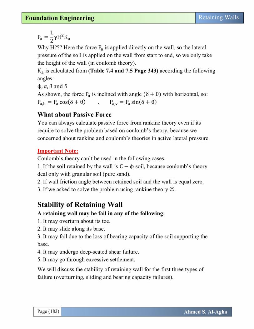
Coulomb’s Theory: Coulomb’s theory discussed in Ch.7 will remains unchanged (without any modifications) in this chapter. The force P is applied directly on the wall, so whole soil retained by the wall will be considered in P and thereby the weight of soil will not apply on the heel of the wall.
θ
β
θ
δ
α
Page (183) Ahmed S. Al-Agha
Foundation Engineering Retaining Walls
P =12
γH K
Why H??? Here the force P is applied directly on the wall, so the lateral pressure of the soil is applied on the wall from start to end, so we only take the height of the wall (in coulomb theory). K is calculated from (Table 7.4 and 7.5 Page 343) according the following angles: ϕ, α, β and δ As shown, the force P is inclined with angle (δ + θ) with horizontal, so: P , = P cos(δ + θ) , P , = P sin(δ + θ)
What about Passive Force You can always calculate passive force from rankine theory even if its require to solve the problem based on coulomb’s theory, because we concerned about rankine and coulomb’s theories in active lateral pressure.
Important Note: Coulomb’s theory can’t be used in the following cases: 1. If the soil retained by the wall is C − ϕ soil, because coulomb’s theory deal only with granular soil (pure sand). 2. If wall friction angle between retained soil and the wall is equal zero. 3. If we asked to solve the problem using rankine theory .
Stability of Retaining Wall A retaining wall may be fail in any of the following: 1. It may overturn about its toe. 2. It may slide along its base. 3. It may fail due to the loss of bearing capacity of the soil supporting the base. 4. It may undergo deep-seated shear failure. 5. It may go through excessive settlement.
We will discuss the stability of retaining wall for the first three types of failure (overturning, sliding and bearing capacity failures).
Page (184) Ahmed S. Al-Agha
Foundation Engineering Retaining Walls
We will use rankine theory to discusses the stability of these types of failures. Coulomb’s theory will be the same with only difference mentioned above (active force applied directly on the wall).
Stability for Overturning
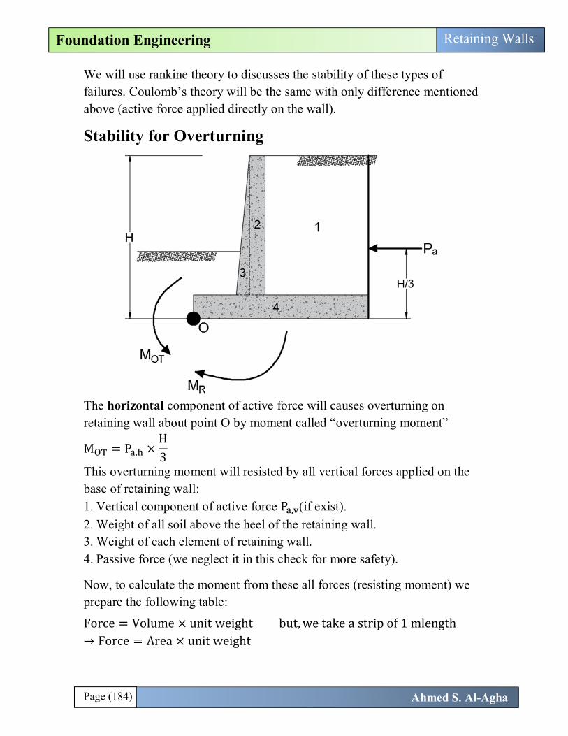
The horizontal component of active force will causes overturning on retaining wall about point O by moment called “overturning moment”
M = P , ×H3
This overturning moment will resisted by all vertical forces applied on the base of retaining wall: 1. Vertical component of active force P , (if exist). 2. Weight of all soil above the heel of the retaining wall. 3. Weight of each element of retaining wall. 4. Passive force (we neglect it in this check for more safety).
Now, to calculate the moment from these all forces (resisting moment) we prepare the following table:
Force = Volume × unit weight but, we take a strip of 1 mlength → Force = Area × unit weight

Page (185) Ahmed S. Al-Agha
Foundation Engineering Retaining Walls
Section Area Weight/unit length of the wall
Moment arm measured from O
Moment about O
1 A W =A × γ X M
2 A W = A × γ X M
3 A W = A × γ X M 4 A W = A × γ X M P , (if exist). B M
V M = M
γ = unit weight of the soil above the heel of RW
FS = ≥ 2
Note: If you asked to consider passive force→ consider it in the resisting moment and the factor of safety remains 2. (So we neglect it here for safety).
Stability for Sliding along the Base

Page (186) Ahmed S. Al-Agha
Foundation Engineering Retaining Walls
Also, the horizontal component of active force may causes movement of the wall in horizontal direction (i.e. causes sliding for the wall), this force is called driving force F = P , . This driving force will be resisted by the following forces: 1. Adhesion between the soil (under the base) and the base of retaining wall: c = adhesion along the base of RW (KN/m) C = c × B = adhesion force under the base of RW (KN) c can be calculated from the following relation: c = K c c = cohesion of soil under the base So adhesion force is: C = K c B
2. Friction force due to the friction between the soil and the base of RW: Always friction force is calculated from the following relation: F = μ N Here N is the sum of vertical forces calculated in the table of the first check (overturning) → N = ∑ V (including the vertical component of active force) μ = coefficient of friction (related to the friction between soil and base) μ = tan(훿 ) δ = K ϕ →→ μ = tan(K ϕ ) ϕ = friction angle of the soil under the base.
→ F = V × tan(K ϕ )
Note:
K = K =12
→23
if you are not given them → take K = K =23
3. Passive force P .(Calculated using rankine theory). So the total resisting force F can be calculated as following:
F = V × tan(K ϕ ) + K c B + P
Factor of safety against sliding:
FS =FF
≥ 2 (if we consider P in F )
FS =FF
≥ 1.5 (if we dont consider P in F )
Page (187) Ahmed S. Al-Agha
Foundation Engineering Retaining Walls
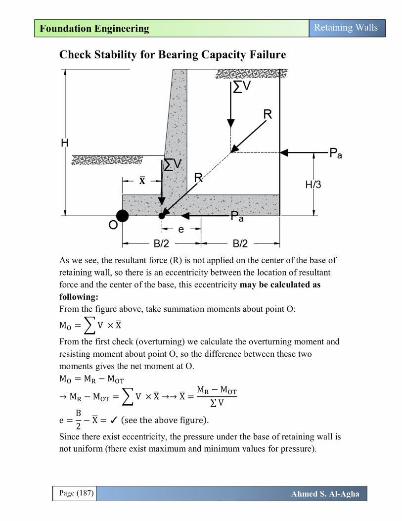
Check Stability for Bearing Capacity Failure
As we see, the resultant force (R) is not applied on the center of the base of retaining wall, so there is an eccentricity between the location of resultant force and the center of the base, this eccentricity may be calculated as following: From the figure above, take summation moments about point O:
M = V × X
From the first check (overturning) we calculate the overturning moment and resisting moment about point O, so the difference between these two moments gives the net moment at O. M = M − M
→ M − M = V × X →→ X =M − M
∑ V
e =B2
− X = ✓ (see the above figure).
Since there exist eccentricity, the pressure under the base of retaining wall is not uniform (there exist maximum and minimum values for pressure).
퐗

Page (188) Ahmed S. Al-Agha
Foundation Engineering Retaining Walls
We calculate qmax and qmin as stated in chapter 3: Eccentricity in B-direction and retaining wall can be considered strip footing If 퐞 < 퐁
ퟔ
q =∑ V
B × 11 +
6eB
q =∑ V
B × 11 −
6eB
If 퐞 > 퐁ퟔ
q , =4 ∑ V
3 × 1 × (B − 2e)
Now, we must check for q : q ≤ q → q = q (at critical case)
FS . =q
q≥ 3
Calculation of 퐪퐮: q is calculated using Meyerhof equation as following:
Page (189) Ahmed S. Al-Agha
Foundation Engineering Retaining Walls
q = cN F F F + qN F F F + 0.5BγN F F F
Where c = Cohesion of soil under the base q = Effective stress at the level of the base of retaining wall. q = γ × D D here is the depth of soil above the toe = D (above figure) → q = γ × D γ = unit weight of the soil under the base of the RW.
Important Note: May be a water table under the base or at the base or above the base (three cases discussed in chapter 3) is the same here, so be careful don’t forget Ch.3. B = B = B − 2e N , N , N = Myerhof bearing capacity factors (Table3.3)according the friction angle for the soil under the base F = F = F = 1 (since RW is considered a strip footing)
Depth factors: (We use B not B ) Here since the depth D is restively small to width of the base B, in most cases 퐃
퐁≤ ퟏ →→
1. 퐅퐨퐫 훟 = ퟎ. ퟎ
F = 1 + 0.4DB
F = 1
F = 1
2. 퐅퐨퐫 훟 > ퟎ. ퟎ
F = F −1 − FN tanϕ
F = 1 + 2 tanϕ (1 − sinϕ) DB
F = 1

Page (190) Ahmed S. Al-Agha
Foundation Engineering Retaining Walls
Inclination Factors: Note that the resultant force applied on the base of the foundation is not vertical, but it is inclined with angle β = Ψ (with vertical), this angle can be calculated as following:
β = Ψ = tanP ,∑ V
F = F = 1 −β°
90
F = 1 −β°
ϕ°
Problems: 1. The cross section of the cantilever retaining wall shown below. Calculate the factor of safety with respect to overturning, sliding, and bearing capacity.
γ = 18 kN/m ϕ = 30° C = 0.0
γ = 19 kN/m ϕ = 24° C = 40kN/m
γ = 24 kN/m

Page (191) Ahmed S. Al-Agha
Foundation Engineering Retaining Walls
Solution
Since it is not specified a method for solving the problem, directly we use Rankine theory. Now draw a vertical line starts from the right-down corner till reaching the backfill line and then calculate active force (P ):
tan 10 =d
2.6→ d = 2.6 × tan 10 = 0.458m
H = 6.7 + d = 6.7 + 0.458 = 7.158m
Now we calculate P :
P =12
× γ × H′ × K
Since the backfill is inclined and the wall is vertical, K is calculated from Table 7.1 according the values of α = 10 and ϕ = 30: K = 0.3495
→ P =12
× 18 × 7.158 × 0.3495 = 161.2 kN
Location of P : Location= = . = 2.38 The force P is inclined with angle α = 10 with horizontal: P , = 161.2 cos(10) = 158.75 , P , = 161.2 sin (10) = 28
Page (192) Ahmed S. Al-Agha
Foundation Engineering Retaining Walls
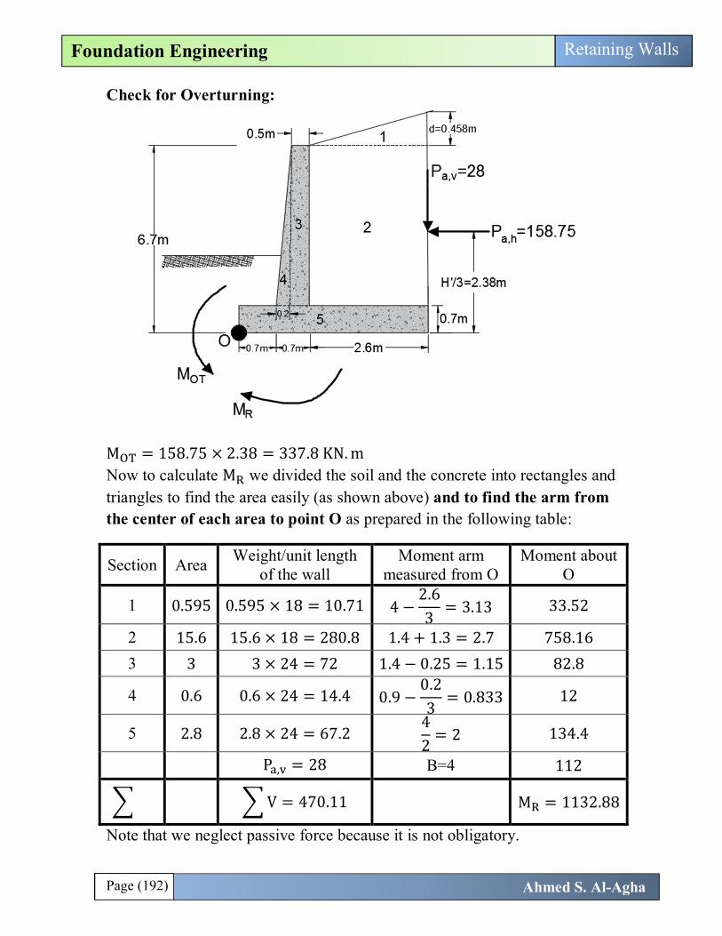
Check for Overturning:
M = 158.75 × 2.38 = 337.8 KN. m Now to calculate M we divided the soil and the concrete into rectangles and triangles to find the area easily (as shown above) and to find the arm from the center of each area to point O as prepared in the following table:
Section Area Weight/unit length of the wall
Moment arm measured from O
Moment about O
1 0.595 0.595 × 18 = 10.71 4 −2.63
= 3.13 33.52
2 15.6 15.6 × 18 = 280.8 1.4 + 1.3 = 2.7 758.16
3 3 3 × 24 = 72 1.4 − 0.25 = 1.15 82.8
4 0.6 0.6 × 24 = 14.4 0.9 −0.23
= 0.833 12
5 2.8 2.8 × 24 = 67.2 42
= 2 134.4
P , = 28 B=4 112
V = 470.11 M = 1132.88
Note that we neglect passive force because it is not obligatory.
Page (193) Ahmed S. Al-Agha
Foundation Engineering Retaining Walls
FS = = ..
= 2.99 > 2 → 퐎퐊 ✓.
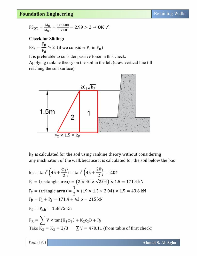
Check for Sliding:
FS =FF
≥ 2 (if we consider P in F )
It is preferable to consider passive force in this check. Applying rankine theory on the soil in the left (draw vertical line till reaching the soil surface).
k is calculated for the soil using rankine theory without considering any iniclination of the wall, because it is calculated for the soil below the bas
k = tan 45 +ϕ2
= tan 45 +202
= 2.04
P = (rectangle area) = 2 × 40 × √2.04 × 1.5 = 171.4 kN
P = (triangle area) =12
× (19 × 1.5 × 2.04) × 1.5 = 43.6 kN
P = P + P = 171.4 + 43.6 = 215 kN
F = P , = 158.75 Kn
F = V × tan(K ϕ ) + K c B + P
Take K = K = 2/3 ∑ V = 470.11 (from table of first check)
2C k
γ × 1.5 × k
Page (194) Ahmed S. Al-Agha
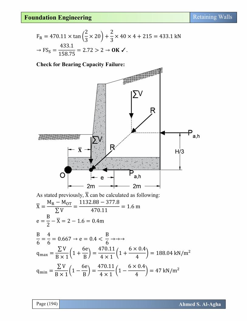
Foundation Engineering Retaining Walls
F = 470.11 × tan23
× 20 +23
× 40 × 4 + 215 = 433.1 kN
→ FS =433.1
158.75= 2.72 > 2 → 퐎퐊 ✓.
Check for Bearing Capacity Failure:
As stated previously, X can be calculated as following:
X =M − M
∑ V=
1132.88 − 377.8470.11
= 1.6 m
e =B2
− X = 2 − 1.6 = 0.4m
B6
=46
= 0.667 → e = 0.4 < B6
→→→
q =∑ V
B × 11 +
6eB
=470.114 × 1
1 +6 × 0.4
4= 188.04 kN/m
q =∑ V
B × 11 −
6eB
=470.114 × 1
1 −6 × 0.4
4= 47 kN/m
퐗

Page (195) Ahmed S. Al-Agha
Foundation Engineering Retaining Walls
Calculation of 퐪퐮 (퐟퐨퐫 퐭퐡퐞 퐬퐨퐢퐥 퐛퐞퐥퐨퐰 퐭퐡퐞 퐛퐚퐬): q = cN F F F + qN F F F + 0.5BγN F F F c = 40 , q = 1.5 × 19 = 28.5 , γ = 19 B = B = B − 2e = 4 − 2(0.4) = 3.2m Shape factors = 1 (RW can be considered strip footing). For ϕ = 20 → N = 14.83 , N = 6.4 , N = 5.39 (from table 3.3)
Depth factors: (We use B not B ) DB
=1.54
= 0.375 < 1 and ϕ = 20 > 0.0 →→
F = 1 + 2 tanϕ (1 − sinϕ) DB
= 1 + 2 tan20 (1 − sin20) (0.375) = 1.12
F = F −1 − FN tanϕ
= 1.12 −1 − 1.12
14.83 × tan20= 1.14
F = 1
Inclination Factors:
β = Ψ = tanP ,∑ V
= tan158.75470.11
= 18.6 (with vertical)
F = F = 1 −β°
901 −
18.690
= 0.63
F = 1 −β°
ϕ° = 1 −18.620
= 0.07
→ q = 40 × 14.83 × 1.14 × 0.63 + 28.5 × 6.4 × 1.12 × 0.63 +0.5 × 3.2 × 19 × 5.39 × 1 × 0.07 → q = 566.2 kN/m
FS . =q
q=
566.2188.04
= 3.01 > 3 (slightly satisfied)퐎퐊 ✓.
Page (196) Ahmed S. Al-Agha
Foundation Engineering Retaining Walls
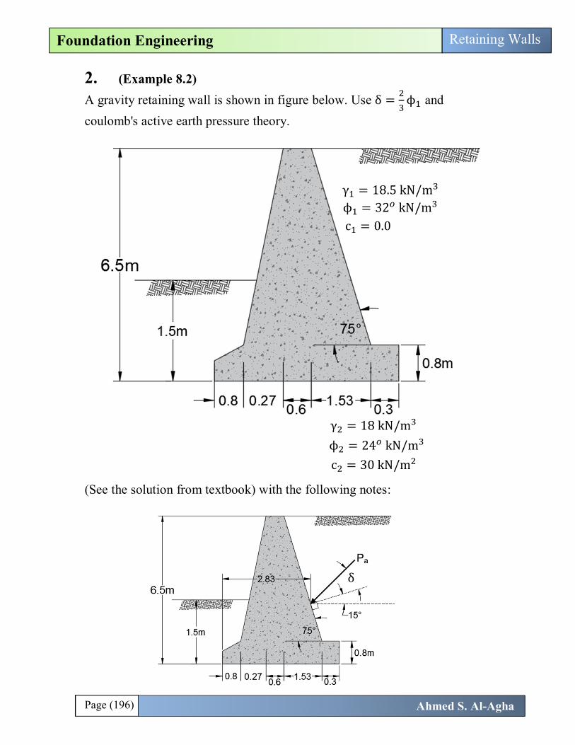
2. (Example 8.2) A gravity retaining wall is shown in figure below. Use δ = ϕ and coulomb's active earth pressure theory.
(See the solution from textbook) with the following notes:
γ = 18.5 kN/m
ϕ = 32 kN/m
c = 0.0
γ = 18 kN/m
ϕ = 24 kN/m
c = 30 kN/m
δ

Page (197) Ahmed S. Al-Agha
Foundation Engineering Retaining Walls
1. As seen the force P is applied directly on the wall. 2. The force P is inclined with angle δ with the normal to the wall and inclined with angle (δ + 15) with horizontal. 3. The distance 2.83 (arm of vertical component of P from toe corner) is not given and can be calculated as following:
The location of force P is = . = 2.167 2.167 − 0.8 = 1.367
tan(75) =1.367
X→ X =
1.367tan (75)
→ X = 0.366 m
2.83 = (3.5 − 0.3) − 0.366
4. Note that when we want to calculate passive force (in overturning pressure) we use rankine theory for the following two reasons: The soil below the base is C − ϕ soil, so we can’t use coulomb’s theory because it deals only with granular soil. It is required to use coulomb’s theory in calculating of active force, however in calculating passive force we can always use rankine theory. 5. In calculating summation of vertical forces, the weighs if soil above the heel are not taken in consideration because the force is applied directly on the wall. 6. Always when calculating P the height of the wall (H) is always taken even if the backfill is inclined because the force applied directly on the wall. 7. (After these notes, solve the problem by yourself ).

Page (198) Ahmed S. Al-Agha
Foundation Engineering Retaining Walls
3. For the retaining wall shown below. a. Find the lateral earth pressure distribution. b. Compute Pa (Rankine). c. Calculate Overturning stability. d. Compute Sliding safety factor. e. Locate the resultant on the base of the footing and determine the eccentricity. f. Calculate the factor of safety against bearing capacity failure.
Solution We use rankine theory because there is no friction between the soil and the wall. a. Calculation of active lateral earth pressure distribution:
σ , = (q + γH)K − 2c K K = tan 45 −ϕ2
γ = 115 pcf
C = 400 psf
ϕ = 28
γ = 130 pcf
C = 750 psf
ϕ = 35
후퐜 = ퟏퟓퟎ 퐩퐜퐟
Page (199) Ahmed S. Al-Agha
Foundation Engineering Retaining Walls
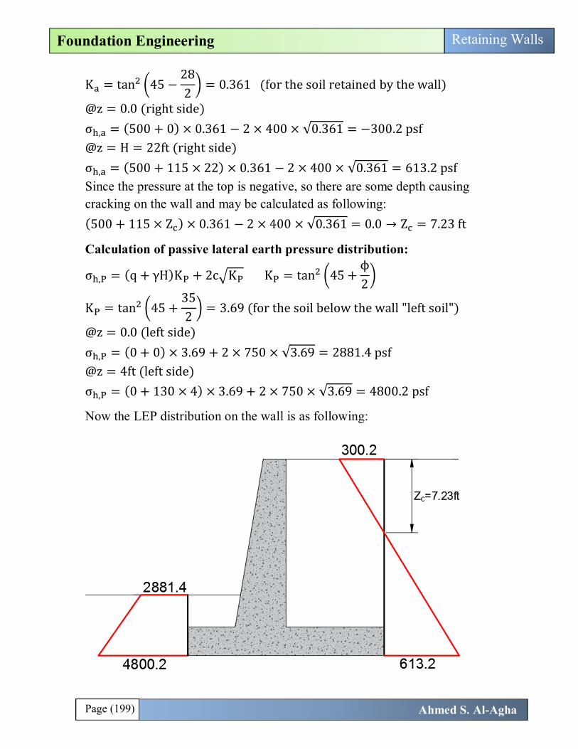
K = tan 45 −282
= 0.361 (for the soil retained by the wall)
@z = 0.0 (right side) σ , = (500 + 0) × 0.361 − 2 × 400 × √0.361 = −300.2 psf @z = H = 22ft (right side) σ , = (500 + 115 × 22) × 0.361 − 2 × 400 × √0.361 = 613.2 psf Since the pressure at the top is negative, so there are some depth causing cracking on the wall and may be calculated as following: (500 + 115 × Z ) × 0.361 − 2 × 400 × √0.361 = 0.0 → Z = 7.23 ft
Calculation of passive lateral earth pressure distribution:
σ , = (q + γH)K + 2c K K = tan 45 +ϕ2
K = tan 45 +352
= 3.69 (for the soil below the wall "left soil")
@z = 0.0 (left side) σ , = (0 + 0) × 3.69 + 2 × 750 × √3.69 = 2881.4 psf @z = 4ft (left side) σ , = (0 + 130 × 4) × 3.69 + 2 × 750 × √3.69 = 4800.2 psf
Now the LEP distribution on the wall is as following:
Page (200) Ahmed S. Al-Agha
Foundation Engineering Retaining Walls
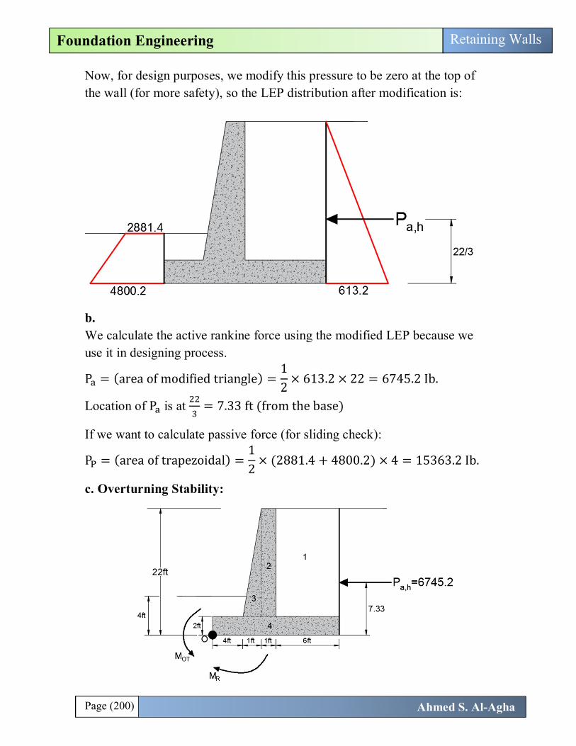
Now, for design purposes, we modify this pressure to be zero at the top of the wall (for more safety), so the LEP distribution after modification is:
b. We calculate the active rankine force using the modified LEP because we use it in designing process.
P = (area of modified triangle) =12
× 613.2 × 22 = 6745.2 Ib.
Location of P is at = 7.33 ft (from the base)
If we want to calculate passive force (for sliding check):
P = (area of trapezoidal) =12
× (2881.4 + 4800.2) × 4 = 15363.2 Ib.
c. Overturning Stability:
Page (201) Ahmed S. Al-Agha
Foundation Engineering Retaining Walls
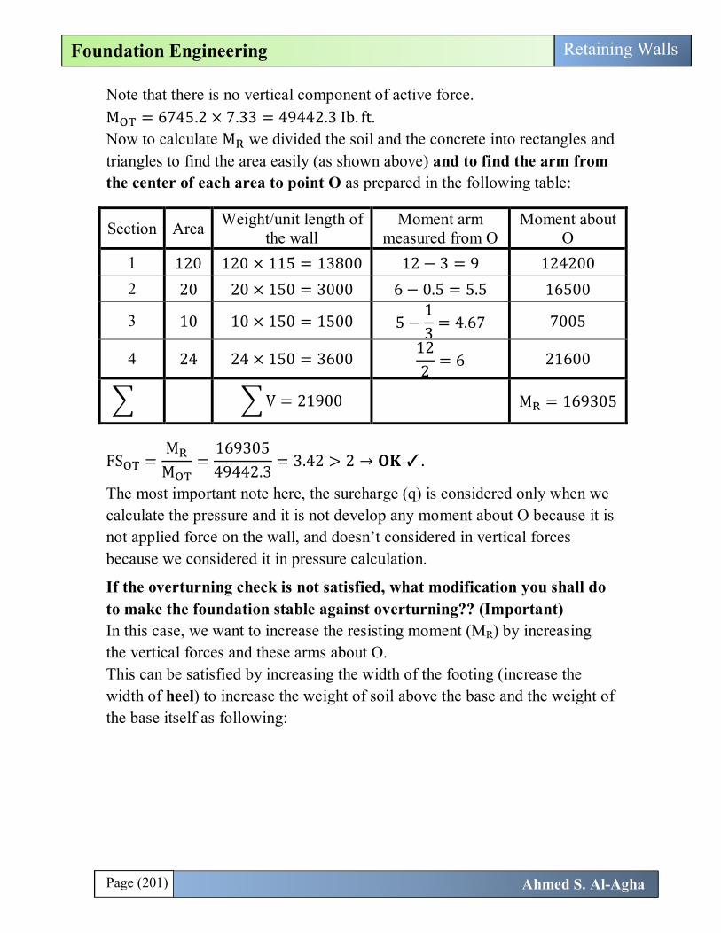
Note that there is no vertical component of active force. M = 6745.2 × 7.33 = 49442.3 Ib. ft. Now to calculate M we divided the soil and the concrete into rectangles and triangles to find the area easily (as shown above) and to find the arm from the center of each area to point O as prepared in the following table:
Section Area Weight/unit length of the wall
Moment arm measured from O
Moment about O
1 120 120 × 115 = 13800 12 − 3 = 9 124200
2 20 20 × 150 = 3000 6 − 0.5 = 5.5 16500
3 10 10 × 150 = 1500 5 −13
= 4.67 7005
4 24 24 × 150 = 3600 122
= 6 21600
V = 21900 M = 169305
FS =M
M=
16930549442.3
= 3.42 > 2 → 퐎퐊 ✓.
The most important note here, the surcharge (q) is considered only when we calculate the pressure and it is not develop any moment about O because it is not applied force on the wall, and doesn’t considered in vertical forces because we considered it in pressure calculation.
If the overturning check is not satisfied, what modification you shall do to make the foundation stable against overturning?? (Important) In this case, we want to increase the resisting moment (MR) by increasing the vertical forces and these arms about O. This can be satisfied by increasing the width of the footing (increase the width of heel) to increase the weight of soil above the base and the weight of the base itself as following:
Page (202) Ahmed S. Al-Agha
Foundation Engineering Retaining Walls
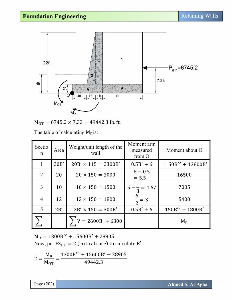
M = 6745.2 × 7.33 = 49442.3 Ib. ft.
The table of calculating M is:
Section Area Weight/unit length of the
wall
Moment arm measured from O
Moment about O
1 20B′ 20B′ × 115 = 2300B′ 0.5B + 6 1150B + 13800B
2 20 20 × 150 = 3000 6 − 0.5= 5.5
16500
3 10 10 × 150 = 1500 5 −13
= 4.67 7005
4 12 12 × 150 = 1800 62
= 3 5400
5 2B′ 2B × 150 = 300B 0.5B + 6 150B + 1800B
V = 2600B + 6300 M
M = 1300B + 15600B + 28905 Now, put FS = 2 (critical case) to calculate B′
2 =M
M=
1300B + 15600B + 2890549442.3
Page (203) Ahmed S. Al-Agha
Foundation Engineering Retaining Walls
1300B + 15600B − 69979.6 = 0.0
Now, in this problem if we calculate B here, it will be less than 6ft, because calculated the FS is 3.42>2 (as calculated above) and here we put it 2. So, if the FS is not satisfied (<2) do the above procedures and calculate the new value of B and then: The final footing width is: B = 6 + B (must be larger than original value of B).
d. Check for sliding:
FS =FF
≥ 2 (if we consider P in F )
F = P , = 6745.2 Ib F = V × tan(K ϕ ) + K c B + P
Take K = K = 2/3 ∑ V = 21900 (from table of first check)
F = 21900 × tan23
× 35 +23
× 750 × 12 + 15363.2 = 30809.94 Ib.
→ FS =30809.94
6745.2= 4.57 > 2 → 퐎퐊 ✓.
If the Sliding stability not satisfied, what modifications you shall do: Solution (1): Increase the base width of the footing (width of the heel) to increase vertical forces:
F = V × tan(K ϕ ) + K c B + P
V = 2600B + 6300 (as calculted above in terms of B )
FS =FF
= 2 (at critical case)
Now the value of B can be calculated and then calculate the new width of the footing.
Solution (2): Use a base key (beam) of depth D under the base of the wall, this base key increase the passive force as following:

Page (204) Ahmed S. Al-Agha
Foundation Engineering Retaining Walls
As we see, this base key increase the passive force and thereby increase the value of F and factor of safety. @z = 4 + D σ , = (0 + 130 × (4 + D)) × 3.69 + 2 × 750 × √3.69 = 4800.2 psf
P =12
× (2881.4 + 4800.2 + 479.7 D) × (4 + D)
You may ask the following tow question (in this case):
1. If a base key of depth 1.5m is constructed under the base of the foundation, calculate the factor of safety against sliding.
P =12
× (2881.4 + 4800.2 + 479.7 × 1.5) × (4 + 1.5) = 23103.16 Ib.
F = 21900 × tan23
× 35 +23
× 750 × 12 + 23103.16 = 38549.94 Ib
→ FS =38549.94
6745.2= 5.7
Note that the FS increase when we use base key.
2. If the sliding stability is not satisfied, find the depth of base key located under the base key to make the wall sable against sliding.
Here, the passive force is a function of D (base key depth), so calculate the value of F in terms of D, and then:

Page (205) Ahmed S. Al-Agha
Foundation Engineering Retaining Walls
FS =F
6745.2= 2 → F = ✓ → D = ✓.
e.
X =M − M
∑ V=
169305 − 49442.321900
= 5.47ft
e =B2
− X = 6 − 5.47 = 0.53 ft.
B6
=126
= 2 → e = 0.53 < B6
→→→
q =∑ V
B × 11 +
6eB
=2190012 × 1
1 +6 × 0.53
12= 2308.6 psf
q =∑ V
B × 11 −
6eB
=2190012 × 1
1 −6 × 0.53
12= 1341.4 psf
Calculation of 퐪퐮 (퐟퐨퐫 퐭퐡퐞 퐬퐨퐢퐥 퐛퐞퐥퐨퐰 퐭퐡퐞 퐛퐚퐬): q = cN F F F + qN F F F + 0.5BγN F F F c = 750 , q = 4 × 130 = 520 , γ = 130 B = B = B − 2e = 12 − 2(0.53) = 10.94 ft Shape factors = 1 (RW can be considered strip footing).
X

Page (206) Ahmed S. Al-Agha
Foundation Engineering Retaining Walls
For ϕ = 35 → N = 46.12 , N = 33.3 , N = 48.03 (from table 3.3)
Depth factors: (We use B not B ) DB
=4
12= 0.333 < 1 and ϕ = 35 > 0.0 →→
F = 1 + 2 tanϕ (1 − sinϕ) DB
= 1 + 2 tan35 (1 − sin35) (0.333) = 1.084
F = F −1 − FN tanϕ
= 1.084 −1 − 1.084
46.12 × tan35= 1.086
F = 1
Inclination Factors:
β = Ψ = tanP ,∑ V
= tan6745.221900
= 17.12 (with vertical)
F = F = 1 −β°
901 −
17.1290
= 0.65
F = 1 −β°
ϕ° = 1 −17.12
35= 0.51
→ q = 750 × 46.12 × 1.086 × 0.65 + 520 × 33.3 × 1.084 × 0.65 +0.5 × 10.94 × 130 × 48.03 × 1 × 0.51 → q = 54036.54
FS . =q
q=
54036.542308.6
= 23.4 > 3 퐎퐊 ✓.
Page (207) Ahmed S. Al-Agha
Foundation Engineering Retaining Walls
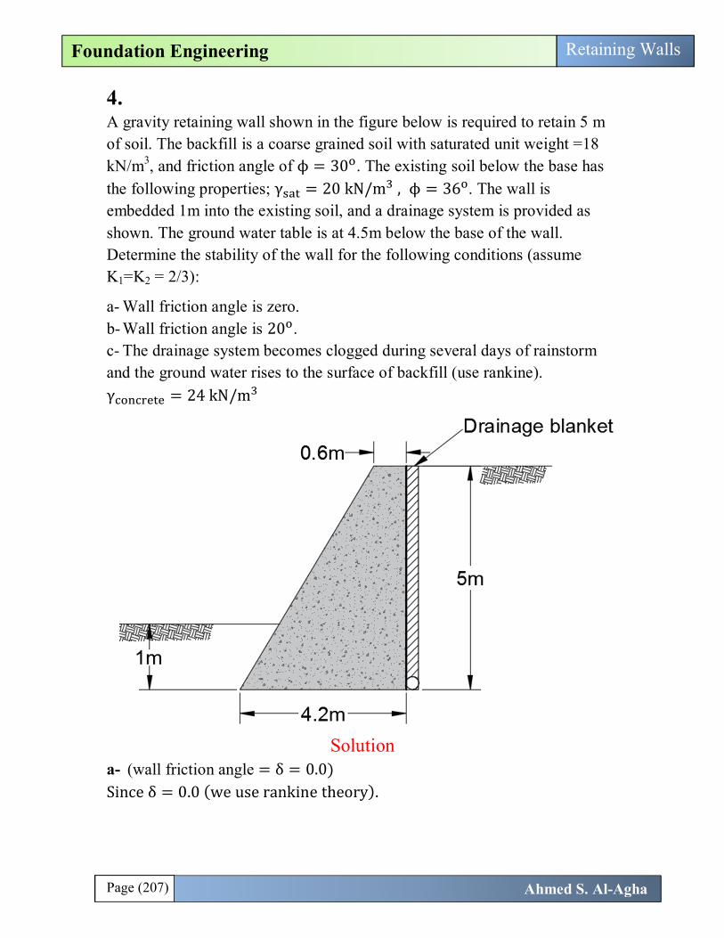
4. A gravity retaining wall shown in the figure below is required to retain 5 m of soil. The backfill is a coarse grained soil with saturated unit weight =18 kN/m3, and friction angle of ϕ = 30 . The existing soil below the base has the following properties; γ = 20 kN/m , ϕ = 36 . The wall is embedded 1m into the existing soil, and a drainage system is provided as shown. The ground water table is at 4.5m below the base of the wall. Determine the stability of the wall for the following conditions (assume K1=K2 = 2/3):
a- Wall friction angle is zero. b- Wall friction angle is 20 . c- The drainage system becomes clogged during several days of rainstorm and the ground water rises to the surface of backfill (use rankine). γ = 24 kN/m
Solution a- (wall friction angle = δ = 0.0) Since δ = 0.0 (we use rankine theory).

Page (208) Ahmed S. Al-Agha
Foundation Engineering Retaining Walls
(The unit weight of the soil (natural) is not given, so we consider the saturated unit weight is the natural unit weight).
K = tan 45 −ϕ2
= tan 45 −302
= 0.333 (for the retained soil)
K = tan 45 +ϕ2
= K = tan 45 +362
= 3.85 (for soil below the base)
Calculation of active lateral earth pressure distribution: σ , = (q + γH)K − 2c K @z = H = 5m (right side) σ , = (0 + 18 × 5) × 0.333 − 0 = 29.97 kN/m
Calculation of passive lateral earth pressure distribution: σ , = (q + γH)K + 2c K @z = 1m(left side) σ , = (0 + 20 × 1) × 3.85 + 0 = 77 kN/m
Calculation of active force:
P = (area of right triangle) =12
× 29.97 × 5 = 74.9 kN
Calculation of passive force:
P = (area of left triangle) =12
× 77 × 1 = 38.5 kN
Page (209) Ahmed S. Al-Agha
Foundation Engineering Retaining Walls
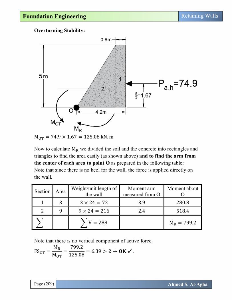
Overturning Stability:
M = 74.9 × 1.67 = 125.08 kN. m
Now to calculate M we divided the soil and the concrete into rectangles and triangles to find the area easily (as shown above) and to find the arm from the center of each area to point O as prepared in the following table: Note that since there is no heel for the wall, the force is applied directly on the wall.
Section Area Weight/unit length of the wall
Moment arm measured from O
Moment about O
1 3 3 × 24 = 72 3.9 280.8
2 9 9 × 24 = 216 2.4 518.4
V = 288 M = 799.2
Note that there is no vertical component of active force
FS =M
M=
799.2125.08
= 6.39 > 2 → 퐎퐊 ✓.
Page (210) Ahmed S. Al-Agha
Foundation Engineering Retaining Walls
Sliding Stability:
FS =FF
≥ 2 (if we consider P in F )
F = P , = 74.9 kN/m F = V × tan(K ϕ ) + K c B + P
Take K = K = 2/3 ∑ V = 288 (from table of first check) P = 38.5 kN/m (as calculated above)
F = 288 × tan23
× 36 +23
× 0 × 4.2 + 38.4 = 166.62 kN.
→ FS =166.62
74.9= 2.2 > 2 → 퐎퐊 ✓.
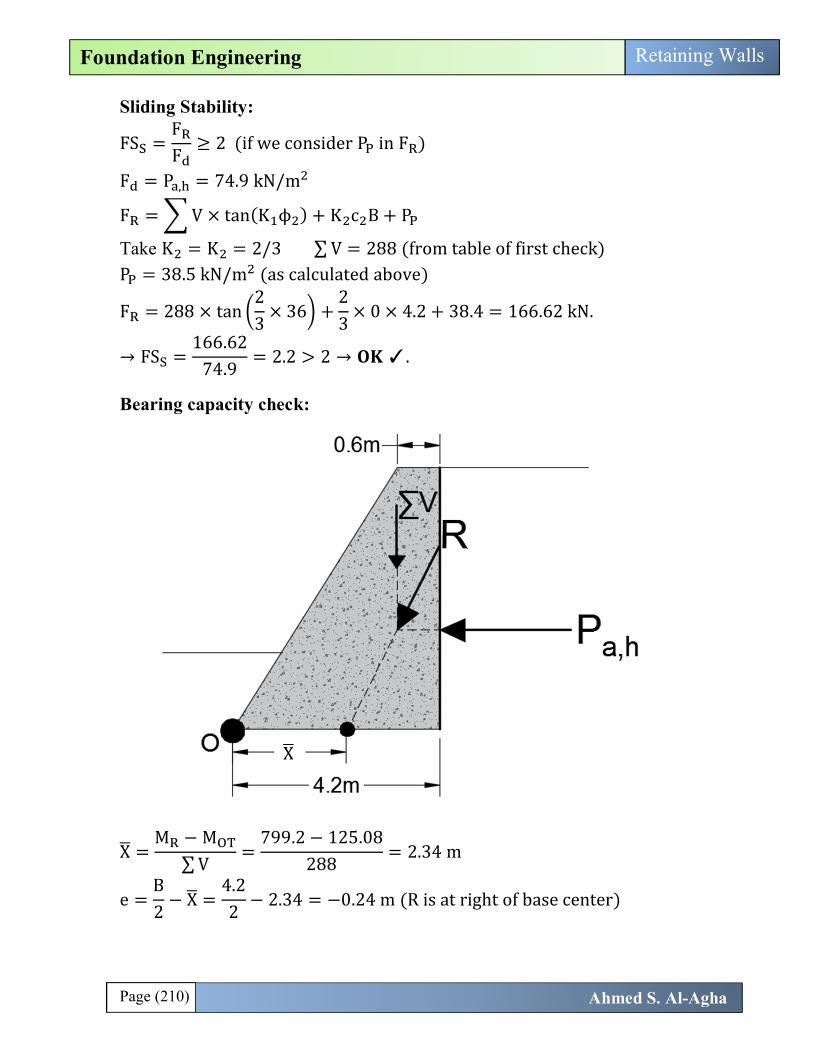
Bearing capacity check:
X =M − M
∑ V=
799.2 − 125.08288
= 2.34 m
e =B2
− X =4.22
− 2.34 = −0.24 m (R is at right of base center)
X
Page (211) Ahmed S. Al-Agha
Foundation Engineering Retaining Walls
B6
=4.26
= 0.7 → e = 0.24 < B6
→→→
q =∑ V
B × 11 +
6eB
=288
4.2 × 11 +
6 × 0.244.2
= 92.08 kN/m
q =∑ V
B × 11 −
6eB
=288
4.2 × 11 −
6 × 0.244.2
= 45.06 kN/m
Calculation of 퐪퐮 (퐟퐨퐫 퐭퐡퐞 퐬퐨퐢퐥 퐛퐞퐥퐨퐰 퐭퐡퐞 퐛퐚퐬): q = cN F F F + qN F F F + 0.5BγN F F F c = 0.0 , q = 1 × 20 = 20 Water table is at distance 4.5m > B=4.2m >>> no effect of water table. → γ = 20 B = B = B − 2e = 4.2 − 2(0.24) = 3.72m Shape factors = 1 (RW can be considered strip footing). For ϕ = 36 → N = 50.59, N = 37.75 , N = 56.31 (from table 3.3)
Depth factors: (We use B not B ) DB
=1
4.2= 0.238 < 1 and ϕ = 36 > 0.0 →→
F = 1 + 2 tanϕ (1 − sinϕ) DB
= 1 + 2 tan36 (1 − sin36) (0.238) = 1.058
F = F −1 − FN tanϕ
= 1.058 −1 − 1.058
50.59 × tan36= 1.06
F = 1
Inclination Factors:
β = Ψ = tanP ,∑ V
= tan74.9288
= 14.6 °(with vertical)
F = F = 1 −β°
901 −
14.690
= 0.7
F = 1 −β°
ϕ° = 1 −17.12
36= 0.59
→ q = 0.0 + 20 × 37.75 × 1.058 × 0.7 +0.5 × 3.72 × 20 × 56.31 × 1 × 0.59

Page (212) Ahmed S. Al-Agha
Foundation Engineering Retaining Walls
→ q = 1795 kN/m
FS . =q
q=
179592.08
= 19.5 > 3 퐎퐊 ✓.
b- (wall friction angle = δ = 20) Since δ = 20 (we use coulomb s theory for active pressure ). Here, the active force is not horizontal, but it is inclined by angle δ = 20 with horizontal:
P = × γ × H × k
δ = 20 , ϕ = 30 → δ =23
ϕ →→
k in this case is calculated from (Table 7.4 P.343) β = 90 , α = 0 , ϕ = 30 →→ k = 0.2973
P =12
× 18 × 5 × 0.2973 = 66.9 kN
This force having horizontal and vertical components: P , = 66.9 cos(20) = 62.86 KN P , = 66.9 sin(20) = 22.88 kN
Calculation of passive force always done by rankine theory (i.e. passive force doesn’t change from first required) P = 38.5 kN (as calculate in first required)
Now, you can complete the solution without any problems .
δ = 20°

Page (213) Ahmed S. Al-Agha
Foundation Engineering Retaining Walls
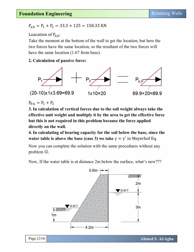
c- When the ground water rises to the surface, the retaining wall is shown below:
What differ??? If we want to use rankine theory (force from soil is gorizontal): 1. Calculation of active force:
Don’t forget we calculate effective stress every change, and the we add water alone.
P = (force due to effective soil) =12
× 13.32 × 5 = 33.3 kN
P = (force due to water) =12
× 50 × 5 = 125 KN
Page (214) Ahmed S. Al-Agha
Foundation Engineering Retaining Walls
P , = P + P = 33.3 + 125 = 158.33 KN
Loacation of P , : Take the moment at the bottom of the wall to get the location, but here the two forces have the same location, so the resultant of the two forces will have the same location (1.67 from base).
2. Calculation of passive force:
P , = P + P 3. In calculation of vertical forces due to the soil weight always take the effective unit weight and multiply it by the area to get the effective force but this is not required in this problem because the force applied directly on the wall. 4. In calculating of bearing capacity for the soil below the base, since the water table is above the base (case 3) we take γ = γ in Meyerhof Eq.
Now you can complete the solution with the same procedures without any problem .
Now, If the water table is at distance 2m below the surface, what’s new???

Page (215) Ahmed S. Al-Agha
Foundation Engineering Retaining Walls
Calculation of Active force:
Here we calculate the effective stress every change, and then added the water alone from its beginning: P , = P + P + P +P To find the location of P , take summation moment at the base of the wall.
Calculation of passive force will not change
The weight of soil above heel (when heel exist), we divide the soil above the heel for two areas, soil above water table and soil below water table. The area of soil above water table is multiplied by natural unit weight, and the area of soil below water table is multiplied by effective unit weight. In calculating of bearing capacity, the water is still above the base, so we use effective unit weight in Meyerhof Eq.

Page (216) Ahmed S. Al-Agha
Foundation Engineering Retaining Walls
The last idea in this chapter: If you are asked to solve this problem (in case of water table) using Coulomb’s theory:
As stated above, the force here will be inclined by angle δ = 20 with horizontal. Calculation of Active force:
Calculation of P :
P =12
× γ × H × k γ = γ = 18 − 10 = 8
δ = 20 , ϕ = 30 → δ =23
ϕ →→
Page (217) Ahmed S. Al-Agha
Foundation Engineering Retaining Walls
k in this case is calculated from (Table 7.4 P.343) β = 90 , α = 0 , ϕ = 30 →→ k = 0.2973
P =12
× 8 × 5 × 0.2973 = 29.73 kN
This force having horizontal and vertical components: P , = 29.73 cos(20) = 27.93 KN P , = 29.73 sin(20) = 10.17 kN
Calculation of P :
P = (force due to water) =12
× 50 × 5 = 125 KN
Calculation of 퐚퐜퐭퐢퐯퐞 퐟퐨퐫퐜퐞: P , = P , + P = 27.93 + 125 = 152.93 kN P , = P , = 10.17 kN
Calculation of 퐩퐚퐬퐬퐢퐯퐞 퐟퐨퐫퐜퐞: Will not changes because always we can use rankine theory in calculating of passive force.
Other notes remains the same.