chapter 8 planning gps control surveys - the university …utdallas.edu/~aiken/gpsclass/ch8.pdf ·...
TRANSCRIPT

EM 1110-1-10031 Aug 96
Chapter 8Planning GPS Control Surveys
8-1. General
Using differential carrier phase GPS surveying to establishcontrol for USACE civil and military projects requiresoperational and procedural specifications that are a proj-ect-specific function of the control being established. Toaccomplish these surveys in the most efficient and cost-effective manner, and to ensure that the required accuracycriteria are obtained, a detailed survey planning phase isessential. This chapter defines GPS survey design criteriaand related observing specifications required to establishcontrol for USACE military construction and civil worksprojects. Information on cost for GPS surveys can befound in Chapter 12, and information on using GPS forhydrographic surveys can be found in EM 1110-2-1003.
8-2. Required Project Control Accuracy
The first step in planning GPS control surveys is to deter-mine the ultimate accuracy requirements. Survey accu-racy requirements are a direct function of specific projectfunctional needs, that is, the basic requirements needed tosupport planning, engineering design, maintenance, opera-tions, construction, or real estate. This is true regardlessof whether GPS or conventional surveying methods areemployed to establish project control. Most USACEmilitary and civil works engineering/construction activitiesrequire relative accuracies (i.e., accuracies between adja-cent control points) ranging from 1:1,000 to 1:50,000,depending on the nature and scope of the project. FewUSACE projects demand relative positional accuracieshigher than the 1:50,000 level (Second-Order, Class I).Since the advent of GPS survey technology, there hasbeen a tendency to specify higher accuracies than neces-sary. Specifying higher accuracy levels than those mini-mally required for the project can unnecessarily increaseproject costs.
a. Project functional requirements.Project function-al requirements must include planned and future design,construction, and mapping activities. Specific controldensity and accuracy are designed from these functionalrequirements.
(1) Density of control within a given project is deter-mined from factors such as planned construction, site planmapping scales, master plan mapping scale, and dredgingand hydrographic survey positioning requirements.
(2) The relative accuracy for project control is alsodetermined based on mapping scales, design/constructionneeds, type of project, etc. Most site plan mapping fordesign purposes is performed and evaluated relative toAmerican Society of Photogrammetry and Remote Sens-ing (ASPRS) standards. These standards apply to photo-grammetric mapping, plane table mapping, total stationmapping, etc. Network control must be of sufficientrelative accuracy to enable hired-labor or contracted sur-vey forces to reliably connect their supplemental mappingwork.
b. Minimum accuracy requirements.Project controlsurveys shall be planned, designed, and executed toachieve the minimum accuracy demanded by the project’sfunctional requirements. In order to most efficiently uti-lize USACE resources, control surveys shall not bedesigned or performed to achieve accuracy levels thatexceed the project requirements. For instance, if a Third-Order, Class I accuracy standard (1:10,000) is required foroffshore dredge/survey control on a navigation project,field survey criteria shall be designed to meet this mini-mum standard.
c. Achievable GPS accuracy.As stated previously,GPS survey methods are capable of providing signifi-cantly higher relative positional accuracies with only min-imal field observations, as compared with conventionaltriangulation, trilateration, or EDM traverse. Although aGPS survey may be designed and performed to supportlower accuracy project control requirements, the actualresults could generally be several magnitudes better thanthe requirement. Although higher accuracy levels arerelatively easily achievable with GPS, it is important toconsider the ultimate use of the control on the project inplanning and designing GPS control networks. Thus,GPS survey adequacy evaluations should be based on theproject accuracy standards, not those theoretically obtain-able with GPS.
(1) For instance, an adjustment of a pair of GPS-established points may indicate a relative distance accu-racy of 1:800,000 between them. These two points maybe subsequently used to set a dredging baseline using1:2,500 construction survey methods; and from 100-ft-spaced stations on this baseline, cross sections are pro-jected using 1:500 to 1:1,000 relative accuracy methods(typical hydrographic surveys). Had the GPS-observedbaseline been accurate only to 1:20,000, such a closurewould still have easily met the project’s functionalrequirements.
8-1

EM 1110-1-10031 Aug 96
(2) Likewise, in plane table topographic (site plan)mapping or photogrammetric mapping work, the differ-ence between 1:20,000 and 1:800,000 relative accuraciesis not perceptible at typical USACE mapping/constructionscales (1:240 to 1:6,000), or ensuring supplemental com-pliance with ASPRS standards. In all cases of planimetricand topographic mapping work, the primary control net-work shall be of sufficient accuracy such that ASPRSstandards can be met when site plan mapping data arederived from such points. For most large-scale militaryand civil mapping work performed by USACE, Third-Order relative accuracies are adequate to control planimet-ric and topographic features within the extent of a givensheet/map or construction site. On some projects cover-ing large geographical areas (e.g., reservoirs, levee sys-tems, installations), this Third-Order mapping control mayneed to be connected to/with a Second-Order (Class Ior II) network to minimize scale distortions over longerreaches of the project.
(3) In densifying control for GIS databases, the func-tional accuracy of the GIS database must be kept inperspective with the survey control requirements. Per-forming 1:100,000 accuracy surveys for a GIS level con-taining 1-acre cell definitions would not be cost-effective;sufficient accuracy could be obtained by scaling relativecoordinates from a U.S. Geological Survey (USGS) quad-rangle map.
8-3. General GPS Network Design Factors
Some, but not all, of the factors to be considered indesigning a GPS network (and subsequent observingprocedure) should include the following:
a. Project size. The extent of the project will affectthe GPS survey network shape. Many civil works naviga-tion and flood control projects are relatively narrow inlateral extent but may extend for many miles longitudi-nally. Alternatively, military installations or reservoir/recreation projects may project equally in length andbreadth. The optimum GPS survey design will vary con-siderably for these different conditions.
b. Required density of control.The type of GPSsurvey scheme used will depend on the number and spac-ing of points to be established, which is a project-specificrequirement. In addition, maximum baseline lengthsbetween stations and/or existing control are also pre-scribed. Often, a combination of GPS and conventionalsurvey densification will prove to be the most cost-effective approach.
c. Absolute GPS reference datums.Coordinate datafor GPS baseline observations are referenced and reducedrelative to WGS 84, an earth-centered (geocentric) coordi-nate system. This system is not directly referenced to butis closely related to, for all practical purposes, GRS 80upon which North American Datum of 1983 (NAD 83) isrelated (for CONUS work). GPS data reduction andadjustment are normally performed using the WGS 84earth-centered (geocentric) coordinate system (X-Y-Z),with baseline vector components (∆X, ∆Y, ∆Z) measuredrelative to this coordinate system. Although baseline vec-tors are measured relative to the WGS 84 system, formost USACE engineering and construction applicationsthese data may be used in adjustments on NAD 27(Clarke 1866). (See paragraphs 3-4 and 4-1.)
(1) If the external network being connected (andadjusted to) is the published NAD 83, the GPS baselinecoordinates may be directly referenced on the GRS 80ellipsoid since they are nearly equal. All supplementalcontrol established is therefore referenced to the GRS 80/NAD 83 coordinate system.
(2) If a GPS survey is connected to NAD 27(SPCS 27) stations which were not adjusted to theNAD 83 datum, then these fixed points may be trans-formed to NAD 83 coordinates using USACE programCORPSCON (see EM 1110-1-1004) and the baselinereductions and adjustment performed relative to theGRS 80 ellipsoid. This method is recommended forUSACE projects, only if resurveying is not a viableoption.
(3) Alternatively, GPS baseline connections toNAD 27 (SPCS 27) project control may be reduced andadjusted directly on that datum with resultant coordinateson the NAD 27. Geocentric coordinates on the NAD 27datum may be computed using the transformation algo-rithms given in Chapter 11. Refer also to EM 1110-1-1004 regarding state plane coordinate transforms betweenSPCS 27 and SPCS 83 grids. Conversions of finaladjusted points on the NAD 27 datum to NAD 83 mayalso be performed using CORPSCON.
(4) Ellipsoid heights h referenced to the GRS 80ellipsoid differ significantly from the orthometric eleva-tions H on NGVD 29, NAVD 88, or dynamic/hydraulicelevations on the IGLD 55, IGLD 85. This difference(geoid separation, orN) can usually be ignored for hori-zontal control. This impliesN is assumed to be zero andh = H where the elevation may be measured, estimated,or scaled at the fixed point(s). See Chapter 6 for usingGPS for vertical surveys.
8-2

EM 1110-1-10031 Aug 96
(5) Datum systems other than NAD 27/NAD 83 willbe used in OCONUS locations. Selected military opera-tional requirements in CONUS may also require non-NAD datum references. It is recommended that GPSbaselines be directly adjusted on the specific projectdatum.
d. Connections to existing control.For most staticand kinematic GPS horizontal control work, at least twoexisting control points should be connected for referenc-ing and adjusting a new GPS survey (Table 8-1). Exist-ing points may be part of the NGRS or in-place projectcontrol which has been adequately used for years. Addi-tional points may be connected if practical. In someinstances, a single existing point may be used to generatespurred baseline vectors for supplemental constructioncontrol.
(1) Connections with existing project control. Thefirst choice for referencing new GPS surveys is the exist-ing project control. This is true for most surveying, notjust GPS, and has considerable legal basis. Unless a new-ly authorized project is involved, long-established projectcontrol reference points should be used. If the project iscurrently on a local datum, then a supplemental tie to theNGRS should be considered as part of the project.
(2) Connections with NGRS. Connections with theNGRS (i.e., National Ocean Service/National GeodeticSurvey control on NAD 83) are preferred where prudentand practical. As with conventional USACE surveying,such connections to the NGRS are not mandatory. Inmany instances, connections with the NGRS are difficultand may add undue cost to a project with limitedresources. When existing project control is known to beof poor accuracy, then ties (and total readjustment) to theNGRS may be warranted. Sufficient project funds shouldhave been programmed to cover the additional costs ofthese connections, including data submittal and review ef-forts if such work is intended to be included in theNGRS. (See paragraph 1-8c regarding advance program-ming requirements.)
(3) Mixed NGRS and project control connections.On existing projects, NGRS-referenced points should notbe mixed with existing project control. This is especiallyimportant if existing project control was poorly connectedwith the older (NAD 27) NGRS, or if the method of thisoriginal connection is uncertain. Since NGRS control hasbeen readjusted to NAD 83 (including subsequent high-precision HARNS readjustments of NAD 83) and mostUSACE project control has not, problems may result if
these schemes are mixed indiscriminately. If a decision ismade to establish and/or update control on an existingproject, and connections with the NGRS (NAD 83/86) arerequired, then all existing project control points must beresurveyed and readjusted. Mixing different referencesystems can result in different datums, with obviousadverse impacts on subsequent construction or boundaryreference. It is far preferable to use “weak” existing(long-established) project control (on NAD 27 or what-ever datum) for reference than to end up with a mixtureof different systems or datums. See EM 1110-1-1004 forfurther discussion.
(4) Accuracy of connected reference control.Ideally, connections should be made to control of a higherorder of accuracy than that intended for the project. Incases where NGRS control is readily available, this isusually the case. However, when only existing projectcontrol is available, connection and adjustment will haveto be performed using that reference system, regardless ofits accuracy. GPS baseline measurements should be per-formed over existing control to assess its accuracy andadequacy for adjustment, or to configure partially con-strained adjustments.
(5) Connection constraints. Although Table 8-1requires only a minimum of two existing stations to reli-ably connect GPS static and kinematic surveys, it mayoften be prudent to include additional NGRS and/or pro-ject points, especially if the existing network is of poorreliability. Adding additional points provides redundantchecks on the surrounding network. This allows for theelimination of these points should the final constrainedadjustment indicate a problem with one or more of thefixed points.
(a) Table 8-1 indicates the maximum allowable dis-tance from the existing network that GPS baselines shouldextend.
(b) Federal Geodetic Control Subcommittee (FGCS)GPS standards (FGCC 1988) require connections to bespread over different quadrants relative to the surveyproject. Other GPS standards suggest an equilateral dis-tribution of fixed control about the proposed survey area.These requirements are unnecessary for USACE work.The value shown in Table 8-1 (for Second-Order, Class I)is only suggested and not mandatory.
e. Location feasibility and field reconnaissance.Agood advance reconnaissance of all marks within theproject is crucial to the expedient and successful
8-3

EM 1110-1-10031 Aug 96
Table 8-1GPS Survey Design, Geometry, Connection, and Observing Criteria
Classification OrderCriterion 2nd, I 2nd, II 3rd, I 3rd, II
Relative accuracyppm1 part in
2050k
5020k
10010k
2005k
Required connections to existinghorizontal control
NGRS networkLocal project network
W/F/PYes
Baseline observation check required overexisting control
Yes W/F/P W/F/P No
Number of connections with existing network(NGRS or local project control)MinimumOptimum
23
23
22
22
New point spacing, m, not less than 1,000 500 200 100
Maximum distance from network to nearestcontrol point in project, km 50 50 50 50
Minimum network control quadrant location(relative to project center) 2 N/R N/R N/R
Multiple station occupations (static GPS surveys)
% Occupied three times N/R N/R N/R N/R
% Occupied two times N/R N/R N/R N/R
Repeat baseline observations(% of total baselines) 0 0 0 0
Master or fiducial stations required W/F/P No No No
Loop closure requirements:
Maximum number of baselines/loop 10 20 20 20
Maximum loop length, km, not to exceed 100 200 N/R N/R
Loop misclosure, ppm, not less than 20 50 100 200
Single spur baseline observations
Allowed per order/class No No Yes Yes
Number of sessions/baseline - - 2 2
Required tie to NGRS - - No No
Field observing criteria -- static GPS surveys
Required antenna phase height measurement per session 2 2 2 2
Meteorological observations required No No No No
Two frequency L1/L2 observations required:< 50-km lines> 50-km lines
NoYes
NoYes
NoYes
NoYes
(Continued)
8-4

EM 1110-1-10031 Aug 96
Table 8-1(Concluded)
Classification OrderCriterion 2nd, I 2nd, II 3rd, I 3rd, II
Recommended minimum observing time (per session), min 60 45 30 30
Minimum number of sessions per GPS baseline 1 1 1 1
Satellite quadrants observed (minimum number) 3 W/F/P N/R N/R N/R
Minimum obstruction angle above horizon, deg 15 15 15 15
Maximum HDOP/VDOP during session N/R N/R N/R N/R
Photograph and/or pencil rubbing required A/R No No No
Kinematic GPS surveying
Allowable per survey class Yes Yes Yes Yes
Required tie to NGRS W/F/P W/F/P No No
Measurement time/baseline, min (follow manufacturer’s specifications) A/R
Minimum number of reference points: 2 2 1-2 1
Preferred references 2 2 2 1
Maximum PDOP 15
Minimum number of observations from each reference station 2 2 2 2
Adjustment and data submittal requirements
Approximate adjustments allowed Yes Yes Yes Yes
Contract acceptance criteriaType of adjustmentEvaluation statisticError ellipse sizesHistograms
Free (unconstrained)Relative distance accuracies
(not used as criteria)(not used as criteria)
Reject criteriaStatisticStandard
Normalized residual±3 * SEUW
Optimum/nominal weightingHorizontalVertical
Optimum variance of unit weight
± 5 + 2 ppm± 10 + 2 ppm
between 0.5 and 1.5
GPS station/session data recording format
Final station descriptions
Bound field survey book or form
Standard DA form
FGCS/NGS Bluebook required
Written project/adjustment report required
No
Yes
Notes:
1. Abbreviations used in this table are explained as follows:W/F/P--Where feasible and practical.N/R--No requirement for this specification--usually indicates variance with provisional FGCC GPS specifications.A/R--As required in specific project instructions or manufacturer’s operating manual.SEUW--Standard error of unit weight.
2. Classification orders refer to intended survey precision for USACE application, not necessarily FGCC standards designed to supportnational network densification.
8-5

EM 1110-1-10031 Aug 96
completion of a GPS survey. The site reconnaissanceshould ideally be completed before the survey is started.The surveyor should also prepare a site sketch and briefdescription on how to reach the point since the individualperforming the site reconnaissance may not be the survey-or that returns to occupy the known or unknown station.
(1) Project sketch. A project sketch should be devel-oped before any site reconnaissance is performed. Thesketch should be on a 7-1/2-min USGS quadrangle mapor other suitable drawing. Drawing the sketch on the mapwill assist the planner in determination of site selectionsand travel distances between stations.
(2) Station descriptions and recovery notes. Stationdescriptions for all new monuments will be developed asthe monumentation is performed. The format of thesedescriptions will follow that stated in EM 1110-1-1002.Recovery notes should be written for existing NGRS net-work stations and project control points, as detailed in EM1110-1-1002. Estimated travel times to all stations shouldbe included in the description. Include road travel time,walking time, and GPS receiver breakdown and setuptime. These times can be estimated while performing theinitial reconnaissance. A site sketch shall also be madeon the description/recovery form. Examples of site recon-naissance reports are shown in Figures 8-1 and 8-2. Ablank reconnaissance report form is included as Work-sheet 8-1 (Figure 8-3), which may be used in lieu of astandard field survey book.
(3) Way point navigation. Way point navigation is anoption on some receivers, allowing the user to enter geo-detic position (usually latitude and longitude) of points ofinterest along a particular route the user may wish tofollow. The GPS antenna, fastened to a vehicle or rangepole, and receiver can then provide the user with naviga-tional information. The navigational information mayinclude the distance and bearing to the point of destina-tion (stored in the receiver), the estimated time to destina-tion, and the speed and course of the user. The resultantmessage produced can then be used to guide the user tothe point of interest. Way point navigation is an optionthat, besides providing navigation information, may behelpful in the recovery of control stations which do nothave descriptions. If the user has the capability of real-time code phase positioning, the way point navigationalaccuracy can be in the range of 0.5 - 10 m.
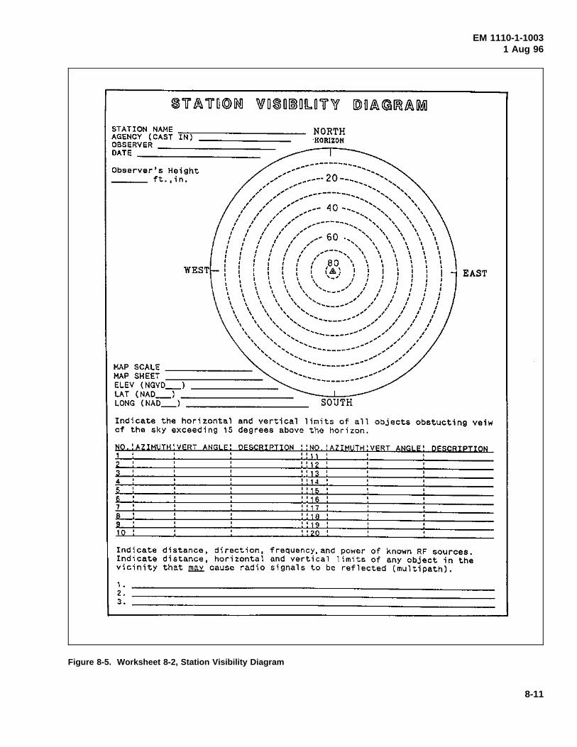
(4) Site obstruction/visibility sketches. The individualperforming the site reconnaissance should record theazimuth and vertical angle of all obstructions. The
azimuths and vertical angles should be determined with acompass and inclinometer. Because obstructions such astrees and buildings cause the GPS signal transmitted fromthe GPS satellite to be blocked, the type of obstruction isalso an important item to be recorded, see Figure 8-2.The type of obstruction is also important to determine ifmultipath might cause a problem. Multipath is caused bythe reflection of the GPS signal by a nearby object pro-ducing a false signal at the GPS antenna. Buildings withreflective surfaces, chain-link fences, and antenna arraysare objects that may cause multipath. The site obstructiondata are needed to determine if the survey site is suitablefor GPS surveying. Obstruction data should be plotted ona Station Visibility Diagram, as shown in Figure 8-4. (Ablank copy of this form is provided as Worksheet 8-2(Figure 8-5).) GPS surveying does require that all sta-tions have an unobstructed view 15 deg above the hori-zon, and satellites below 10 deg should not be observed.
(5) Suitability for kinematic observations. Clear,obstruction-free projects may be suitable for kinematicGPS surveys as opposed to static. The use of kinematicobservations will increase productivity by a factor of 5to 10 over static methods, while still providing adequateaccuracy levels. On many projects, a mixture betweenboth static and kinematic GPS observations may prove tobe most cost-effective.
(6) Monumentation. All monumentation should fol-low the guidelines of EM 1110-1-1002.
(7) On-site physical restrictions. The degree ofdifficulty in occupying points due to such factors as traveltimes, site access, multipath effects, and satellite visibilityshould be anticipated. The need for redundant observa-tions, should reobservations be required, must also beconsidered.
(8) Checks for disturbed existing control. AdditionalGPS baselines may need to be observed between existingNGRS/project control to verify their accuracy and/orstability.
(9) Satellite visibility limitations. For most of theContinental United States, there are at least four to fivesatellites in view at all times. However, some areas mayhave less during times of satellite maintenance orunhealthy satellites. Satellite visibility charts of the GPSsatellite constellation play a major part in optimizing net-work configurations and observation schedules.
8-6

EM 1110-1-10031 Aug 96
Figure 8-1. Sample site reconnaissance sketch
8-7

EM 1110-1-10031 Aug 96
Figure 8-2. Reconnaissance report on condition of survey
8-8

EM 1110-1-10031 Aug 96
Figure 8-3. Worksheet 8-1, Site Reconnaissance Report form
8-9

EM 1110-1-10031 Aug 96
Figure 8-4. Sample station visibility diagram
8-10
EM 1110-1-10031 Aug 96
Figure 8-5. Worksheet 8-2, Station Visibility Diagram
8-11

EM 1110-1-10031 Aug 96
(10) Station intervisibility requirements. Projectspecifications may dictate station intervisibility for azi-muth reference. This may constrain minimum stationspacing.
f. Multiple/repeat baseline connections.Table 8-1lists recommended criteria for baseline connectionsbetween stations, repeat baseline observations, and multi-ple station occupations. Many of these standards weredeveloped by FGCS for performing high-precision geo-detic control surveys such that extensive redundancy willresult from the collected data. Since the purpose of thesegeodetic densification surveys is markedly different fromUSACE control densification, the need for such highobservational redundancy is also different. Adding redun-dant baseline/station occupations may prove prudent onsome remote projects where accessibility is difficult.
g. Loop requirements. Loops (i.e., traverses) pro-vide the mechanism for performing field data validationas well as final adjustment accuracy analysis. Since loopsof GPS baselines are comparable to traditional EDM/tapedtraverse routes, misclosures and adjustments can behandled similarly. Most GPS survey nets (static or kine-matic) end up with one or more interconnecting loops thatare either internal from a single fixed point or externalthrough two or more fixed network points. Loops shouldbe closed off at the spacing indicated in Table 8-1. Loopclosures should meet the criteria specified in Table 8-1,based on the total loop length. See also Chapter 10 foradditional GPS loop closure checks.
(1) GPS control surveys may be conducted by form-ing loops between two or more existing points, with ade-quate cross-connections where feasible. Such alignmentprocedures are usually most practical on civil works navi-gation projects which typically require control to be estab-lished along a linear path, e.g., river or canal embank-ments, levees, beach renourishment projects, and jetties.
(2) Loops should be formed every 10 to 20 baselines,preferably closing on existing control.
(3) Connections to existing control should be made asopportunities exist and/or as often as practical.
(4) When establishing control over relatively largemilitary installations, civil recreation projects, flood con-trol projects, and the like, a series of redundant baselinesforming interconnecting loops is usually recommended.When densifying Second- and Third-Order control for siteplan design and construction, extensive cross-connecting
loop and network configurations recommended by theFGCS for geodetic surveying are not necessary.
(5) On all projects, maximum use of combined staticand kinematic GPS observations should be considered,both of which may be configured to form pseudo-traverseloops for subsequent field data validation and finaladjustment.
8-4. GPS Network Design and Layout
A wide variety of survey configuration methods may beused to densify project control using GPS survey tech-niques. Unlike conventional triangulation, trilateration,and EDM traverse surveying, the shape, or geometry, ofthe GPS network design is not as significant. The follow-ing guidelines for planning and designing proposed GPSsurveys are intended to support lower order (Second-Order, Class I, or 1:50,000 or less accuracy) controlsurveys applicable to USACE civil works and militaryconstruction activities. An exception to this would beGPS surveys supporting structural deformation monitoringprojects where relative accuracies at the centimeter levelor better are required over a small project area.
a. Newly established GPS control may or may notbe incorporated into the NGRS, depending on the ade-quacy of the connection to the existing NGRS network, orwhether it was tied only internally to existing projectcontrol.
b. Of paramount importance in developing a networkdesign is to obtain the most economical coverage withinthe prescribed project accuracy requirements. The opti-mum network design, therefore, provides a minimumamount of baseline/loop redundancy without an unneces-sary amount of “over-observation.” Obtaining this opti-mum design (cost versus accuracy) is difficult andconstantly changing due to evolving GPS technology andsatellite coverage.
c. GPS survey layout schemes.The planning of aGPS survey scheme is similar to that for conventionaltriangulation or traversing. The type of survey designadopted is dependent on the GPS technique employed andthe requirements of the user.
(1) GPS networking. A GPS network is proposedwhen established survey control is to be used in precisenetwork densification (1:50,000-1:100,000). For lowerorder work (i.e., less than 1:50,000), elaborate networkschemes are unnecessary and less work-intensive GPS
8-12

EM 1110-1-10031 Aug 96
survey extension methods may be used. When the net-working method is selected, the surveyor should devise asurvey network that is geometrically sound. Trianglesthat are weak geometrically should be avoided. The net-working method is practical only with static, pseudo-kinematic, and kinematic survey techniques. Figure 8-6shows an example of a step-by-step method to build aGPS survey network.
Figure 8-6. GPS network design
(2) GPS traversing. Traversing is the method ofchoice when the user has only two or three receivers andrequired accuracies are 1:5,000-1:50,000. Traversing withGPS is done similar to conventional methods. Open-endtraverses are not recommended when 1:5,000 accuraciesor greater are required. Since GPS does not provide suf-ficient point positioning accuracies, the surveyor musthave a minimum of one fixed (or known) control point,although three are preferred. A fixed control point is astation with known latitude-longitude-height or easting-northing-height. This point may or may not be part of theNGRS. If only one control point is used and the stationdoes not have a known height, the user will be unable toposition the unknown stations. When performing a looptraverse, the surveyor should observe a check angle orcheck azimuth using conventional survey techniques todetermine if the known station has been disturbed. If
azimuth targets are not visible, and a check angle cannotbe observed, a closed traverse involving one or morecontrol points is recommended. Again, a check angle orcheck azimuth should be observed from the starting con-trol station. If a check angle is not performed, the surveycan still be completed. However, if the survey does notmeet specified closure requirements, the surveyor will beunable to assess what control point may be in error. If acheck angle or check azimuth cannot be observed, a thirdcontrol point should be tied into the traverse (Figure 8-7).This will aid in determining the cause of misclosure.
Figure 8-7. GPS traversing schemes
(3) GPS spur shots. Spurs are an acceptable methodwhen the user has only two receivers or only a few con-trol points are to be established. Spur lines should beobserved twice during two independent observing ses-sions. Once the first session is completed, the receivers ateach station should be turned off and the tripod elevationschanged. This procedure is similar to performing a for-ward and backward level line. It is important that thetripods be moved in elevation and replumbed over thecontrol station between sessions. If this step is not imple-mented, the two baselines cannot be considered indepen-dent. Figure 8-8 shows an example of a spur line. Spursare most applicable to static survey and relative position-ing (code phase) techniques.
8-13

EM 1110-1-10031 Aug 96
Figure 8-8. GPS spur line
8-5. GPS Techniques Needed for Survey
After a GPS network has been designed and laid out, aGPS survey method or technique needs to be considered.The concepts for each method were discussed in Chap-ter 6 and the procedures are discussed in Chapter 9. Themost efficient method should be chosen in order to mini-mize time and cost while meeting the accuracy require-ments of a given survey project. Once a technique ischosen, the following can be set up: equipment require-ments, observation schedules, and sessions designationsand planning functions.
a. General equipment requirements.The type ofGPS instrumentation used on a project depends on theaccuracy requirements of the project, GPS survey tech-nique, project size, and economics. Most USACE proj-ects can be completed using a single-frequency receiver.Dual-frequency receivers are recommended as baselinelengths approach or exceed 50 km. This length may alsovary depending on the amount of solar activity during theobservation period. Using a dual-frequency receiver per-mits the user to solve for possible ionospheric and tropo-spheric delays which can occur as the signal travels fromthe satellite to the receiver antenna.
(1) Number of GPS receivers. The minimum numberof receivers required to perform a differential GPS surveyis two. The actual number used on a project will dependon the project size and number of available instruments/operators. Using more than two receivers will oftenincrease productivity and allow for more efficient fieldobservations. For some kinematic applications, two
reference (set at known points) receivers and at least onerover are recommended.
(2) Personnel. Personnel requirements are also proj-ect dependent. Most GPS equipment is compact and lightweight and only requires one person per station setup.However, some cases where a station is not easily acces-sible or requires additional power for a data link, twoindividuals may be required.
(3) Transportation. One vehicle is normally requiredfor each GPS receiver used on a project. This vehicleshould be equipped to handle the physical conditions thatmay be encountered while performing the field observa-tions. In most cases, a two-wheel-drive vehicle should beadequate for performing all field observations. If adversesite conditions exist, a four-wheel-drive vehicle may berequired. Adequate and reliable transportation is impor-tant when the observation schedule requires moving fromone station to another between observation sessions.
(4) Auxiliary equipment. Adequate power should beavailable for all equipment (receivers, computers, lights,etc.) that will be used during the observations. Computers(386-based recommended), software, and data storagedevices (floppy disks and/or cassette tapes) should beavailable for onsite field data reduction use. Other equip-ment required for conduct of a GPS survey should includetripods, tribrachs, measuring tapes, flagging, flashlights,tools, equipment cables, compass, and inclinometer. Ifreal-time positioning is required, then a data link is alsoneeded.
b. Observation schedules.Planning a GPS surveyrequires that the surveyor determine when satellites willbe visible for the given survey area; therefore, the firststep in determining observation schedules is to plot a sat-ellite visibility plot for the project area. Even when theGPS becomes fully operational, full 24-hr coverage of atleast four satellites may not be available in all areas.
(1) Most GPS manufacturers have software packageswhich at least predict satellite rise and set times. Anexcellent satellite plot will have the following essentialinformation: satellite azimuths, elevations, set and risetimes, and satellite PDOPs for the desired survey area.Satellite ephemeris data are generally required as input forthe prediction software.
(2) To obtain broadcast ephemeris information, aGPS receiver collects data during a satellite window. Thereceiver antenna does not have to be located over a
8-14

EM 1110-1-10031 Aug 96
known point when collecting a broadcast ephemeris. Thedata are then downloaded to a personal computer wherethey are used as input into the software prediction pro-gram. Besides ephemeris data for the software, the useris generally required to enter approximate latitude andlongitude (usually scaled from a topographic map) andtime offset from UTC for the survey area.
(3) From the satellite plot, the user can determine thebest time to perform a successful GPS survey by takingadvantage of the best combination of satellite azimuths,elevations, and PDOPs as determined by the satellitevisibility plot for the desired survey area (for furtherinformation on favorable PDOP values, refer to Chap-ter 5). The number of sessions and/or stations per daydepends on satellite visibility, travel times between sta-tions, and the final accuracy of the survey. Often, areceiver is required to occupy a station for more than onesession per day.
(4) A satellite polar plot (Figure 8-9), a satelliteazimuth and elevation table (Figure 8-10), and a PDOPversus time plot (Figure 8-11) may be run prior to sitereconnaissance. The output files created by the satelliteprediction software are used in determining if a site issuitable for GPS surveying.
(5) Determination of session times is based mainly onthe satellite visibility plan with the following factors takeninto consideration: time required to permit safe travelbetween survey sites; time to set up and take down theequipment before and after the survey; time of survey;and possible time loss due to unforeseeable problems orcomplications. Station occupation during each sessionshould be designed to minimize travel time in order tomaximize the overall efficiency of the survey.
c. Session designations and planning functions. Asurvey session in GPS terminology refers to a singleperiod of observation. Sessions and station designationsare usually denoted by alphanumeric characters (0, 1, 2,A, B, C, etc.), determined prior to survey commencement.
(1) When only eight numeric characters are permittedfor station/session designations, the following conventionmay be followed:
12345678
where
1 = type of monument with the following conventionbeing recommended:
1 = known horizontal control monument2 = known benchmark3 = known 3D monument4 = new horizontal control monument5 = new benchmark6 = new 3D monument7 = unplanned occupation8 = temporary 2D point9 = temporary 3D point
2, 3, 4 = actual station number given to each station
5, 6, 7 = Julian day of year
8 = session number
(a) Example: Station Identifier: 40011821Position: 12345678
(b) The numeral 4 in the number 1 position indicatesthe monument being established is a new monumentwhere only horizontal position is being established.
(c) The 001 in the number 2, 3, and 4 position is thestation number that has been given to the monument forthis project.
(d) The 182 in the number 5, 6, and 7 position is theJulian day of the year. This is the same day as 1 July.
(e) The numeral 1 in the number 8 position iden-tifies the session number during which observations arebeing made. If the receiver performed observations dur-ing the second session on the same day on the same mon-ument, the session number should be changed to 2 for theperiod of the second session (then the total station identi-fier would be 40011822).
(2) When alpha characters are permitted for station/session designation, then a more meaningful designationcan be assigned to the designation. The date of each sur-vey session should be recorded during the survey as cal-endar dates and Julian days and used in the station/sessiondesignation. Some GPS software programs will requireJulian dates for correct software operation. In addition todetermination of station/session designations before thesurvey begins, the user (usually the crew chief) must:
(a) Determine the occupant of each station.
(b) Determine satellite visibility for each station.
8-15

EM 1110-1-10031 Aug 96
8-16

EM 1110-1-10031 Aug 96
Figure 8-10. Satellite azimuth and elevation table
8-17

EM 1110-1-10031 Aug 96
8-18

EM 1110-1-10031 Aug 96
(c) Require site reconnaissance data for stations to beoccupied. Remember the same person who performed theinitial site reconnaissance may not be the individual per-forming the survey; therefore, prior determined site recon-naissance data may require clarification before surveycommencement.
(d) Develop a project sketch.
(e) Issue explicit instructions on when each session isto begin and end.
(f) Require a station data logging sheet completedfor each station. Figures 8-12 and 8-13 are examples ofvarious station logs used in USACE, along with blankforms which may be used as worksheets. Standard boundfield survey books may be used in lieu of separatelog/work sheets.
8-19

EM 1110-1-10031 Aug 96
Figure 8-12. Sample GPS data logging sheet (Continued)
8-20

EM 1110-1-10031 Aug 96
Figure 8-12. (Concluded)
8-21

EM 1110-1-10031 Aug 96
Figure 8-13. Worksheet 8-3, GPS data logging sheet (Continued)
8-22

EM 1110-1-10031 Aug 96
Figure 8-13. (Concluded)
8-23