chapter 8 petroleum coke
TRANSCRIPT

CHAPTER 8PETROLEUM COKE
Petroleum coke is a black carbonaceous solid material produced as a by-product of delayed coking orfluid coking units in refineries. There is a large world market for petroleum coke as fuel because of itshigh calorific value, low ash, and discount pricing relative to coal. This ensures a ready market for petro-leum coke in power utility stations and cement plants. The largest single nonfuel use of petroleum cokeis in the manufacture of carbon anodes for the aluminum smelting industry which accounts for almost80 percent of all petroleum coke produced. Other important uses of petroleum coke are in the manufac-ture of graphite anodes for electric arc furnaces (used in steel plants, phosphoric acid, and calcium car-bide manufacture) and in titanium dioxide (TiO2) manufacture. Each end use requires a different qualityof petroleum coke. Both physical and chemical characteristics of petroleum coke determine its suitabil-ity for a specific use. Coking is a thermal cracking process used in refineries to maximize residuum con-version to distillates and thus minimize low-value fuel oil production. Petroleum coke is a by-product ofcoker units. If the coke produced has high sulfur and metals, it is sold as fuel for power generation orcement plants. If the by-product coke is of a low sulfur and low metal content, it can be further upgrad-ed in value by the coke calcining process. Calcining reduces the moisture and volatile hydrocarbon con-tent of raw petroleum coke. Calcined coke is used in the manufacture of anodes for aluminum smelting,for graphite electrodes for electric arc furnaces, and many other end uses.
MANUFACTURING PROCESSES
Raw petroleum coke is a by-product of coking units of refineries. There are two coking processes:the fluid coking process and the delayed coking process. Due to their lower capital cost, most ofthe coker units built in refineries use the delayed coking process. Also the properties of the cokeproduced in the fluid coker units are much inferior to that produced in delayed coker units. Forthese reasons, most of the petroleum coke produced in the refineries is from delayed coker units.Coking is a noncatalytic thermal cracking process based on the concept of carbon rejection. Theheaviest hydrogen-deficient portion of feed (asphaltenes, resins, etc.) are rejected as coke, whichcontain essentially all the feed metals and ash and a substantial portion of feed sulfur and nitrogen.Feed sulfur removal from liquid product ranges from 40 to 75 percent, depending upon feed con-radson carbon, and nitrogen removal from liquid product is greater than 50 percent of that of feed.
DELAYED COKING PROCESS
Delayed coking is a thermal cracking process in which feed (vacuum residue or heavy distillates) israpidly heated in a furnace to approximately 800 to 840°F and then confined in a reaction zone (cokedrum) at the proper temperature and pressure until the unvaporized part of the furnace effluent isconverted to vapor and coke. Coking reactions are very complex. Three distinct steps take place:
• Partial vaporization and mild cracking (visbreaking) of feed as it passes through the furnace coil
• Cracking of vapor as it passes through the coke drum
• Successive cracking and polymerization of liquid trapped in the drum until it converts into vaporand coke
141

Products from delayed coking process are gases, gasoline, gas oil, and coke. Coking is anendothermic reaction, with a furnace supplying the necessary heat to complete the coking reactions.Coke produced from the vacuum residue feed is called green coke and used in the manufacture ofcarbon anodes after calcining. The properties of the coke produced are a function of coker feed prop-erties, which in turn depend on the crude processed in the refinery. For example, if crude processedin the refinery has a high sulfur and high metal content, the vacuum residuum produced will alsohave high sulfur and metals and the coke produced will have high sulfur and high metals. For pro-ducing petroleum coke with low metals and low sulfur content suitable for anode making for alu-minum smelters, crude oil processed in the refinery must have a low sulfur and low metal content.The feed to coker units is generally vacuum residue from crude distillation units.
For the production of premium grades of petroleum coke (needle coke) used in making graphiteelectrodes, the feed to the delayed coker is highly aromatic heavy distillates such as desulfurizeddecant oil ex refinery fluid catalytic cracking unit (FCCU) or thermal tars produced from naphthacracker units. Naphtha cracker thermally cracks naphtha or heavier feed in the presence of steam toethylene, propylene, and C4 olefins. Thermal tars are the unconverted residue, highly reactive, high-ly aromatic, used as a feed component for needle coke manufacture.
Raw petroleum coke as produced in a refinery coker unit (green coke) has a high volatile mattercontent (8 to 15 wt % [percent by weight]) and a low density. It is further processed in a coke cal-ciner unit, where it is heated to high temperatures to drive out the volatile matter. The calciningprocess improves coke density, its strength, and its electric conductivity. Calcined coke is suitablefor anode making for the aluminum industry and for other uses such as graphite electrodes manu-facture, TiO2 manufacture, and so on.
Delayed Coking Process Description
Referring to the process flow diagram in Fig. 8-1, vacuum residuum fresh feed enters the coker frac-tionator V-104 bottom surge zone. Fresh feed is mixed with the recycle condensed in the bottom sectionof the fractionator and is pumped by heater charge pump P-101 through coker heater H-101. In the heaterthe charge is rapidly heated to the desired temperature for coke formation. Steam is injected into each ofthe heater coils to maintain the required minimum velocity and residence time and to suppress coke for-mation in heater tubes. The vapor liquid mixture leaving the furnace enters coke drums V-101 or V-102where the trapped liquid is converted to coke and light hydrocarbon vapor. Total vapor leaves the drumto enter the coke fractionator. A minimum of two drums are required. One drum receives furnaceeffluent while the other drum is being decoked. The coker drum overhead vapor flows to coker frac-tionator tower V-104 and enters below the shed section. Coke drum effluent vapor is first quenched withfresh feed and then washed with hot gas oil pumpback in the trayed wash section. These operations cleanand cool the effluent product vapor and condense a recycle stream at the same time. This recycle stream,together with fresh feed, is pumped from the coker fractionator to the coking furnace. The washed vaporpasses to the rectifying section of the tower. A circulating heavy gas oil pumparound stream withdrawnfrom the pumparound pan is used to remove heat from the tower, condensing the major portion of heavygas oil and cooling the ascending vapor. The hot pumparound stream of coker gas oil withdrawn fromthe fractionator is used to reboil the towers either in the vapor recovery plant or for steam generation.The coker gas oil product is air cooled in E-109 to storage temperature. The fractionator overhead vaporis partially condensed in overhead condenser E-101 and E-102 before flowing to fractionator overheaddrum V-105. The vapor is separated from liquid in this drum. Vapor flow under pressure controls thesuction of the gas compressor in the gas recovery section. The top of the fractionator is refluxed with apart of the condensed liquid in the overhead drum via reflux pump P-103. Sour water is withdrawn fromthe overhead drum and routed to the sour water treating facility.
Vapor Recovery
Referring to the process flow diagram in Fig. 8-2, coker gas comes from the fractionator overheaddrum, after passing through knockout drum V-210, and flows to multistage compressor K-201.
142 PETROLEUM SPECIALTY PRODUCTS

Green coke
Fresh feed
Clearwater pump
Coke settlingmaze
Coke dropout
Hydraulic decoking equipment
Decoking water storage tank V-103
S.V
Coker fractionator V-104
Fractionator overhead drum V-105
Fractionator overhead condenserE-101
HeaterchargepumpP-101
BottomrecirculationpumpP-102
Coker gas to gas recovery plant
Sour water
Coker distillates
Coker gas oil
Steam
BFW
Make up water
Coker blowdown drum V-107
Blowdownsettlingdrim V-108
Steam
Condensate
Blowdown circulationcoolerE-108
Coker blowdown condenserE-107
To flare
CWS
CWR
Coker naphtha
Slop oil
Steam
Coke drums V-101, V102
V-101 V-102
V-103
V-104
V-105
V-106
Naphthasidestripper V-106
V-107
V-108
Coker heaterH-101
H-101
E-101
Fractionator trim cooler E-102
E-102
E-103 E-104
E-105 E-106
E-107
E-108
Coker distillate/feed exchanger E-103
Coker distillatecoolerE-104
Coker gas oil/feed exchanger E-105
Coker gas oil coolerE-106
P-101 P-102
Coker naphthapumpP-103
P-104
Coker distillatepumpP-104
Coker gas oil pumpP-105
P-105
Coke drum cooling water pumpP-106
P-106 P-107
Hydraulic decokingwater pump P-107
P-108
Blowdown cicrulation pumpP-108
P-109 P-110
Blowdown water recirculationpumpP-109
SlopoilpumpP-110
P-111
Lean sponge oil pump P-111
Lean sponge oil
Rich sponge oilCGO pump around from reboilers
CGO pump around to reboilers
CGO product cooler E-109
P-103
FIGURE 8-1 Delayed coker unit coking section.
143

Compressorsuctiondrum V-201
Coker gas compressorK-201
V-201
K-201
CompressorinterstagecoolerE-201
E-201
Compressorinterstagedrum V-202
V-202
SpongeabsorberV-203
V-203
High-pressureseparator V-204
V-204
E-202
Rich/leansponge oil exchanger E-202
Lean oil coolerE-203
E-203
P-201
Compressorsuction pump P-201
Debutanizer columnV-205
V-205
Debutanizer overhead condenserE-204
E-204
Debutanizer overhead drum V-206
V-206CWS
CWR
Debutanizer feed pump P-202
P-202
P-203
Debutanizer refluxpump P-203
E-205
Debutanizer reboilerE-205
Naphthasplitter feed pump P-204
P-204
NaphthasplitterV-207
V-207
Naphthasplitteroverhead condenserE-206
E-206
Naphthasplitteroverhead drum V-208
V-208
P-205
Lightnaphtharefluxpump P-205
To flare
E-207
LightnaphthaproductcoolerE-207
E-208
NaphthasplitterreboilerE-208
E-209
Heavy naphthacoolerE-209
Heavy naphthapumpP-206
P-206
Rich sponge oil to fractionator
Sponge oil from fractionator
Coker overhead drum vapor
Coker gas
Sour water
Light naphtha
Heavy naphtha
LPG
CGO pumparound from coker fractionator
CG
O to
frac
taio
nato
r
E-210
CompressoraftercondenserE-210
CWS
CWR
FIGURE 8-2 Delayed coker vapor recovery section.
144

The compressed gas is cooled and any condensed liquid is separated in high-pressure separator V-204.Vapor from the high-pressure separator enters sponge absorber V-203 near the bottom. In the spongeabsorber, a liquid coker distillate stream (sponge oil) withdrawn from the coker fractionator is used toabsorb the heavier hydrocarbons from the gas. The rich sponge oil is returned to the fractionatorcolumn after heat exchange with the incoming lean sponge oil. Coker gas leaving the sponge absorbergoes to a gas processing plant or refinery fuel system. Liquid from high-pressure separator drum V-204is pumped via pump P-202 to a debutanizer column V-205 where butane and lighter gases are removedas top product while the bottom product flows to naphtha splitter column V-207. In the naphtha splittercolumn, the feed is split into a light naphtha cut as overhead product and heavy naphtha cut as bottomproduct.
Coke Drum Decoking
Delayed coking is a batch process, using at least two coke drums. One drum at a time is in opera-tion, receiving hot residuum feed from heater coils, while the other drum is disconnected and isunder the decoking cycle.
The decoking operation consists of the following steps:
1. Steaming. The full coke drum is steamed out to remove any residual oil liquid. The mixture ofsteam and hydrocarbons is first sent to the fractionator and next to the coker blow-down systemwhere hydrocarbons (wax tailings) are recovered.
2. Cooling. The coke drum is water filled and allowed to cool below 200°F. Steam generated duringcooling is condensed in the blow-down system.
3. Draining. The cooling water is drained from the drum and recovered for reuse.
4. Unheading. The top and bottom heads are removed in preparation for coke removal.
5. Decoking. Hydraulic decoking is the most common decoking method. High-pressure waterjets are used to cut the coke from the coke drum. Water is separated from the coke fines andreused.
6. Heading and testing. After the heads are replaced, the drum is tightened, purged, and pressure tested.
7. Heating up. Steam and vapor from hot coke drum are used to heat up the cold coke drum.Condensed water is sent to the blow-down drum. Condensed hydrocarbons are sent to either thecoker fractionator or the blow-down drum.
8. Coking. The heated coke drum is placed on stream and the cycle is repeated.
OPERATING CONDITIONS
Table 8-1 presents the operating conditions of a delayed coker unit processing vacuum residuumfeed. The delayed coker process yields are shown in Table 8-2. Table 8-3 presents the typical prop-erties of feed and the products of a delayed coker unit.
Needle Coke Manufacture
Generally, the feedstock for delayed coker units is vacuum residuum that produces sponge coke.Needle coke is produced in delayed coker units from heavy distillate feedstocks.
There is a great demand in industry for low-sulfur needle coke, which can be processed into graphiteelectrodes. Graphite electrodes are required to have a low coefficient of thermal expansion (CTE) towithstand severe conditions of thermal shock and the stresses encountered in the operation of electric
PETROLEUM COKE 145

steel melting furnaces. The performance of these electrodes depends to a great extent on the character-istics of the needle coke raw material used to fabricate these electrodes. Needle coke for graphiteelectrodes must have a very low CTE (1–2 * 10−7 in/in/°C). Unfortunately, there is a scarcity of high-aromatic, low-sulfur feedstocks required for this premium coke segment. Table 8-4 lists the desirablefeedstock properties for needle coke production.
The Bureau of Mines Correlation Index (BMCI) is a function of the volume average boiling pointand API gravity (Fig. 8-3). BMCI is an indicator of the aromaticity of the feed. The CTE of the cokeproduced is a function of the feed BMCI. As the BMCI increases, the CTE decreases, passes througha minimum value (Fig. 8-4), and increases again.1
Optimum CTE is between 1 to 4 × 10⁻⁷ in/in/°C.BMCI is thus a convenient specification for screeningfeedstocks for needle coke production. Sulfur mustbe below 0.6 percent by weight and ash less than 0.3percent by weight. Higher sulfur can cause puffing ofelectrodes. High ash increases resistivity of electrodesand decreases its mechanical strength. Calcined coke
146 PETROLEUM SPECIALTY PRODUCTS
TABLE 8-2 Delayed Coker Process Yields
Stream Wt fraction
Feed products 1.0000Fuel gases and H2S 0.1190Light naphtha 0.0140Heavy naphtha 0.0530Kerosene 0.1720Diesel 0.3000Coker gas oil 0.1490Coke 0.1930
TABLE 8-1 Delayed Coker Operating Conditions
Operating parameter Units Value
Heater coil outlet temperature °F 927Drum outlet temperature °F 802Drum pressure lb/in2 24.5Flash zone temperature °F 748Unit combined feed ratio 1.24(CFR)
Tower top temperature °F 208Accumulator pressure lb/in2 10.7
TABLE 8-3 Delayed Coker Feed and Product Properties
Coker Light Heavy Property Units feed naphtha naphtha Kerosene Diesel Gas oil Coke
API 80.9 63.9 44.6 29.7 19.9Density g/cc 0.9738 0.6661 0.7242 0.8035 0.8778 0.9346Bulk density Lbs/ft3 47Sulfur Wt % 1.44 0.14 0.21 0.74 1.1 3.2Flash point °FFreeze point °F –54Pour point °F 35.1RVP lb/in2 12.2Conradson Wt % 12.1carbon
RON 81.8Distillation ASTM D 1160 °F
5% 92410% 973 186 335 550 73320% 103130% 107150% 214 390 613 83390% 252 463 699 958
Nitrogen Wt % 0.23Viscosity cSt, 122°F 25.6
TABLE 8-4 Needle Coke Feed Characteristics
Aromatics Wt % Min. 75Sulfur Wt % Max. 0.5Asphaltene Wt % Max. 1.0Boiling point °F >800BMCI 95–130

with high sulfur or ash is not considered suitable even if other key properties meet the quality standardsof needle-grade coke. Thus quality and price of needle-grade coke depends highly on the properties offeedstock used for making needle coke.
Feedstocks
Delayed coker feedstocks for needle coke production are high aromatic, heavy refinery streams suchas the following:
• Decant or slurry oil from fluid catalytic cracking process
• Aromatic extract from lube oil units
• Ethylene cracker pyrolysis tars
PETROLEUM COKE 147
Or
BMCI = + – 456.8
Where:
87552
VABP
67029
133.3 + G
BMCI =
VABP = Volumetric boiling point, °RG = API gravity
SG = Specific gravity
+ 473.7∗ SG – 456.887552
VABP
BMCI = Bureau of Mines Correlation Index
FIGURE 8-3 Bureau of mines correlation index.
50 100 150
Bureau of mines correlation index coker fresh feed
Premium coke region
5
10
15
0
Coe
ffici
ent o
f the
rmal
exp
ansi
on (
CT
E)1
0–7/
°C
FIGURE 8-4 CTE as a function of BMCI.
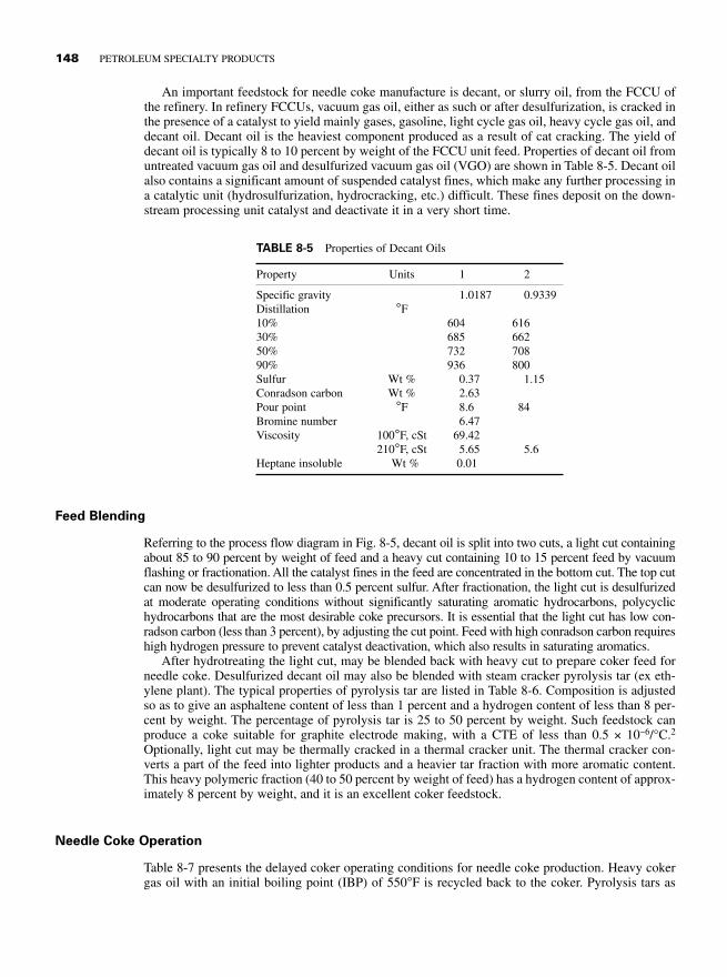
An important feedstock for needle coke manufacture is decant, or slurry oil, from the FCCU ofthe refinery. In refinery FCCUs, vacuum gas oil, either as such or after desulfurization, is cracked inthe presence of a catalyst to yield mainly gases, gasoline, light cycle gas oil, heavy cycle gas oil, anddecant oil. Decant oil is the heaviest component produced as a result of cat cracking. The yield ofdecant oil is typically 8 to 10 percent by weight of the FCCU unit feed. Properties of decant oil fromuntreated vacuum gas oil and desulfurized vacuum gas oil (VGO) are shown in Table 8-5. Decant oilalso contains a significant amount of suspended catalyst fines, which make any further processing ina catalytic unit (hydrosulfurization, hydrocracking, etc.) difficult. These fines deposit on the down-stream processing unit catalyst and deactivate it in a very short time.
148 PETROLEUM SPECIALTY PRODUCTS
TABLE 8-5 Properties of Decant Oils
Property Units 1 2
Specific gravity 1.0187 0.9339Distillation °F10% 604 61630% 685 66250% 732 70890% 936 800Sulfur Wt % 0.37 1.15Conradson carbon Wt % 2.63Pour point °F 8.6 84Bromine number 6.47Viscosity 100°F, cSt 69.42
210°F, cSt 5.65 5.6Heptane insoluble Wt % 0.01
Feed Blending
Referring to the process flow diagram in Fig. 8-5, decant oil is split into two cuts, a light cut containingabout 85 to 90 percent by weight of feed and a heavy cut containing 10 to 15 percent feed by vacuumflashing or fractionation. All the catalyst fines in the feed are concentrated in the bottom cut. The top cutcan now be desulfurized to less than 0.5 percent sulfur. After fractionation, the light cut is desulfurizedat moderate operating conditions without significantly saturating aromatic hydrocarbons, polycyclichydrocarbons that are the most desirable coke precursors. It is essential that the light cut has low con-radson carbon (less than 3 percent), by adjusting the cut point. Feed with high conradson carbon requireshigh hydrogen pressure to prevent catalyst deactivation, which also results in saturating aromatics.
After hydrotreating the light cut, may be blended back with heavy cut to prepare coker feed forneedle coke. Desulfurized decant oil may also be blended with steam cracker pyrolysis tar (ex eth-ylene plant). The typical properties of pyrolysis tar are listed in Table 8-6. Composition is adjustedso as to give an asphaltene content of less than 1 percent and a hydrogen content of less than 8 per-cent by weight. The percentage of pyrolysis tar is 25 to 50 percent by weight. Such feedstock canproduce a coke suitable for graphite electrode making, with a CTE of less than 0.5 × 10⁻⁶/°C.2
Optionally, light cut may be thermally cracked in a thermal cracker unit. The thermal cracker con-verts a part of the feed into lighter products and a heavier tar fraction with more aromatic content.This heavy polymeric fraction (40 to 50 percent by weight of feed) has a hydrogen content of approx-imately 8 percent by weight, and it is an excellent coker feedstock.
Needle Coke Operation
Table 8-7 presents the delayed coker operating conditions for needle coke production. Heavy cokergas oil with an initial boiling point (IBP) of 550°F is recycled back to the coker. Pyrolysis tars as

PETROLEUM COKE 149
Decant oil from FCCU units
Frac
tiona
tor
colu
mn
Hydrodesulfurizer
To fuel oil blending
Delayed coker feedstock for needle coke
Steam cracker tar
Hydrogen
Desulfurized decant oil
Undesulfurized decant oil
Light decant oil 90 vol % of feed
Heavy decant oil approx. 10 vol % of feed
FIGURE 8-5 Needle coke feed blending.
TABLE 8-6 Steam Cracker Tar Properties
Property Units 1 2 3
Specific gravity 1.1238 1.0835 1.1313DistillationIBP 446 340 31110% 554 480 32730% 636.8 550 37650% 734 700 45060% 842 51470% 826Recovery Vol % 68 70 55Mol wt 319 398Carbon Wt % 91.7 90.97 93.1Hydrogen Wt % 6.78 7.62 6.8Nitrogen Wt % 0.21Sulfur Wt % 1.2 0.5 0.22Convadson carbon Wt % 23.1 16 25.1Pour point °F 66 37Bromine number 15.44 17.98 12.88Viscosity 100°F, cSt 4079 1154 14456
210°F 206 27 80Heptane insoluble Wt % 21.1 19.2 22.8

such are unsuitable for the commercial production of premium coke by delayed coking processbecause the tar converts to coke in the coils of the delayed coker furnace after a very short operatingperiod, requiring frequent coil decoking and an uneconomical run length. Coker feed is generally ablend of desulfurized decant oil and pyrolysis tar.
The drum temperature, pressure, and feed recycle ratio are higher than those of conventionalsponge coke operations. A high drum temperature lowers the coke CTE. A furnace fouls more rapid-ly with higher temperatures. Coke becomes harder and coke removal times increase dramaticallywith higher temperatures. A 15°F increase in drum temperature decreased the CTE by 30 percent buttripled the coke cutting time.
FLUID COKING PROCESS
Figure 8-6 shows a simplified process flow diagram of a fluid coker unit, which is very similar to theFCCU of the refinery except that coke is circulated between the reactor and the burner instead of cat-alyst. Unlike delayed coker, fluid coking is a continuous process that uses a fluidized bed reactor tothermally crack petroleum residuum to produce more valuable lighter products such as gas, naphtha,kerosene, diesel, and gas oils. The residue is sprayed into a fluidized bed of hot coke. The use of afluidized bed permits the coking reactions to be conducted at a higher temperature and a shorter con-tact time than that with delayed coking. These conditions result in a lower yield of coke. The processuses two vessels: a reactor and a burner. Coke particles are circulated between these two to transferheat from the burner to the reactor. The heat is generated by burning a part of the coke. The reactorcontains a bed of coke particles that is kept fluidized by the introduction of steam. The residuum feedis injected directly into the reactor and distributed uniformly over the surface of coke particles wherecracking reactions take place, resulting in the formation of lighter products that vaporize. No preheatis necessary because circulating coke particles supply the heat required for coking reactions and thecontrol of reactor temperature. Vapor products leave the bed and pass through the cyclones, whichremoves most of the entrained coke. The vapor is then discharged into the bottom of a scrubberwhere the remaining coke is removed and the product cooled to condense into a heavy tar. The result-ing slurry is recycled back to the coking reactor. The overhead product from the scrubber is sent toa fractionator for the separation of gases, naphtha, and light and heavy gas oils. Coke particles in thereactor flow down into a stripping zone at the base where stripping steam removes any product vaporfrom between the coke particles. The coke then flows down a stand pipe and into a riser, which leadsto a burner. Steam is used to induce the upward flow of coke into a burner. The average bed tem-perature is maintained by regulating air flow as required to burn a part of particulate coke. Operatingconditions of a typical fluid coker are shown in Table 8-8. Flue gases from a burner bed pass throughcyclones and are discharged to a stack through a control valve to control burner pressure. Hot cokeis returned to the reactor through another stand pipe and riser assembly. Because coke is one of theproducts, it must be withdrawn continuously from the burner bed to maintain the coke inventory inthe burner at a constant level. To prevent circulating coke from becoming too coarse, large cokeparticulate is removed through a quench elutriator and replaced with smaller seed particles.Normal coke circulation from the coke burner to the reactor is 5 to 10 lb per pound of feed. Cooledcoke removed from the system is 20 to 200 mesh. Typical yields from a fluid coker unit are listed
150 PETROLEUM SPECIALTY PRODUCTS
TABLE 8-7 Needle Coke Operating Conditions
Operating condition Units
Coke drum temperature °F 880–950Coker drum pressure lb/in2 20–135Combined recycle ratio 0.2–0.8

in Table 8-9. Coke produced by the fluid coking process finds a limited application in the cathodicprotection of pipelines and packing media for anode baking furnaces.
Coke Calcining
Petroleum coke as produced in the delayed coker is a low-valued product that can be used only asfuel for power generation, in the cement industry, and in metallurgical operations. Green coke isprocessed in another processing unit called the coke calcination unit. In the calcining process, rawpetroleum coke is heated to a high temperature in a gas-fired rotary kiln to remove moisture andvolatile matter. The calcination process produces coke that has a higher density, higher physicalstrength, and increased electrical conductivity. Most petroleum coke is calcined in rotary-type kilns.Calcined coke product is used in the aluminum smelting industry for carbon anode manufacture, forgraphite electrode manufacture, for TiO2 production, and also to increase the carbon content of ironand steel products. Green coke specifications suitable for calcining are shown in Table 8-10.
PETROLEUM COKE 151
Steam
Residfeed
Rec
ycle
Gas
Naphtha
Gas oil
Reactor Burner
Combustion gases
Net coke
Air blower
Elutriator
FIGURE 8-6 Fluid coking process.
TABLE 8-8 Fluid Coker Operating Conditions
Operating parameter Units Reactor Burner
Operating temperature °F 950 1025Operating pressure lb/in2 10.2 10.9Fluid velocity ft/s 1–3 2–3Bed depth ft 30–50 10–15

Process Description
Referring to the process flow diagram in Fig. 8-7, raw petroleum coke (green coke) lumps, 50 to 100 mmin size, are fed from feed hopper V-101 to a weigh feeder and then to rotary kiln R-101. A typicalindustrial kiln may be 150 to 250 ft long and 5 to 15 ft in diameter. The kiln is lined inside withrefractory bricks and made of steel. It is rotated with a train of gears. The kiln is sloped down fromthe feed side to the discharge side at a slope of 0.50 to 0.75 in/ft. The coke progresses down thekiln countercurrent to the hot combustion gases. As its temperature increases to maximum, the feedmoisture is driven off and also volatile matter is stripped from the coke. Devolatilization occurs at900 to 1800°F. Further down, in the calcining zone (2200 to 2550°F), dehydrogenation and somedesulfurization reactions occur and coke density increases. The rotary kiln heating zones are shownin Fig. 8-8. At the discharge end, the rotary kiln has a burner in the firing crown. The burner is usedto preheat the refractory before start-up and supply some of the heat for calcining. Most burners arefired by natural gas. The temperature in the kiln is monitored by optical pyrometers. The tempera-ture is controlled by the amount of gas, excess combustion air, kiln rotation speed, and raw coke feedrate. The degree of calcination is estimated from the density and electrical resistivity of the calcinedcoke. Water vapor originating from the moisture in feed coke, hot combustion gases, unburned gases,tar from volatile matter in feed coke, and coke fines flow out from the feed end of the kiln into “AfterBurner” R-102 where excess fuel and coke fines are burned with air. Both the incinerator and kilnare operated under slightly negative pressure using an induced draft fan or a tall stack. Hot gases arerouted through waste heat boiler H-101 or through a bag filter to trap particulate matter before
152 PETROLEUM SPECIALTY PRODUCTS
TABLE 8-9 Fluid Coker Unit Yields
Coker Operation; Recycle Cut Point(RCP) = 975°F
Property Units
Feed Heavy ArabianCut point 700°F +Gravity ° API 11.5Conradson carbon Wt % 14.4Sulfur Wt % 4.5MetalsNI + V ppm 134Product yieldFeed wt fraction 1.0000Products wt fractionH2S 0.0080C3– 0.0710C4 0.0150C5+ 0.7300Gross coke 0.1760Coke burned 0.067Net coke production 0.109
TABLE 8-10 Green Coke Specifications Suitable forCalcining
Property Value
Sulfur Wt % Max. 3.3Vanadium ppmw, Max. 200Nickel ppmw, Max. 300Iron ppmw, Max. 400Volatiles Wt % Max. 11

discharging to stack. The coke residence time in the kiln is 40 to 60 mins, and it drops off thedischarge end into a refractory-lined chute and then into rotary cooler R-103. The cooler is also acylindrical pipe with a smaller diameter of shorter length and rotated at higher revolutions per minutethan the kiln. Water is sprayed into the front end to contact the hot coke, taking advantage of veryhigh heat of vaporization of water for cooling. The coke residence time in the cooler is approxi-mately 20 min after which it is discharged onto a high-temperature conveyer belt or into screw feed-ers. The water spray rate is adjusted to give a product outlet temperature of 250 to 350°F, in order tokeep the calcined product dry. Calcined coke product from the cooler is routed to storage silosthrough a system of conveyer belts and elevators.
PETROLEUM COKE 153
Green coke binV-101
Rotary kiln R-101
Kiln firing hoodK-101
Rotary cooler R-103
After burner R-102
Waste heatboilerH-101
Bag filter F-101
Fuelsupply
Incinerator air fan
Quenchwater
Fuelsupply
Secondary air fan
Calcinedcoke product
Primary air fan
Coolerexhaust air fan
F-101
H-101
Natural fraft stack S-101
S-101
R-102
V-101
Weigh feeder
R-101K-101
R-103
V-102
M
M
Calcined coke conveyor CV-101
CV-101
CV-102
Calcinedcoke bin V-102
FIGURE 8-7 Coke Calcining unit.
Moisturerelease/heat-up zone
100–750°F
Devolatilization/ calcining zone
900–1800°F
Calcined coke zone desulfurization densification
2200–2550°F
Calciner feed
Hot calcined coke to rotary
cooler
FIGURE 8-8 Rotary kiln heating zones.

Operating Variables
Coke in the kiln must be heated at a very slow rate during the initial devolatilization process (930to 1120°F) so that the mesophase or liquid crystal part does not bloat or distort (popcorn) duringthe evolution of the volatile matter. Petroleum coke with anisotropic (needle structure) and/orwith high volatile matter must be calcined with slowed-up heat rates to produce high-density andlow-porosity coke. The quality of calcined coke is a function of the quality of the green coke feedto the calciner unit. Coke from different crude oils produces green coke with different physicalproperties: particle size, density, porosity, structure, volatile matter, and ash content. Feed parti-cle size must be uniform for good control of the residence time of the coke in the kiln. Withoutproper sizing and feeding of the rotary kiln, slides can occur, dumping most of the material outof the kiln. Table 8-11 lists the properties of the industrial calcined coke samples.
154 PETROLEUM SPECIALTY PRODUCTS
TABLE 8-11 Properties of Commercial Calcined Petroleum Cokes
Property Units 1 2 3
Moisture Mass % 0.15 0.15 0.15Ash Mass % 0.3–0.5 0.3–0.5 0.3–0.5Fixed carbon Mass %, Min. 99.00 99.00 99.00Sulfur Mass % 1.3–1.7 1.0–1.3 0.5–0.6Real density g/cc 2.03–2.06 2.03–2.06 2.03–2.06Vibrated bulk density g/cc ( 8–14 MESH) 0.84–0.87 0.97–1.00 0.77–0.80MetalsNickel ppmw 100–200 400–500 250–350Iron ppmw 150–250 200–300 150–250Vanadium ppmw 50–100 400–500 250–350Aluminum ppmw 100–200 200–300 100–200Calcium ppmw 200–300 150–250 200–300
PETROLEUM COKE TYPES
Different physical forms of coke are produced in the delayed coker:
• Sponge coke
• Needle coke
• Shot coke
Sponge Coke
Sponge coke is dull black with an amorphous appearance. It is produced from vacuum resids of lowto moderate asphaltene concentration. Straight run vacuum residues tends to produce a large percent-age of isotropic or amorphous cokes. These are visibly very porous and are called “sponge coke.”They may have some percentage of embedded shot coke. A low shot coke percentage is specified foranode grades of sponge coke. A highly desirable quality of petroleum coke to be used in the pro-duction of carbon anodes is the high grindability index. Grindability is a relative measure of the easewith which coke may be pulverized. Shot coke in sponge coke samples can cause excessive powerconsumption and is thus an undesirable impurity. The addition of 0.5 to 10 percent by weight of anoxygen-containing carbonaceous material (sawdust, lignite, low rank coals, etc.) which decomposeunder coking conditions promote the formation of sponge coke.3

Coke produced from a delayed coker is known as green sponge coke. It is mainly composed ofcarbon but also contains 10 to 15 percent of volatile hydrocarbons together with impurities such assulfur, vanadium, and nitrogen. If green coke has a sufficiently low level of sulfur and metals, it maybe suitable for calcining for making feedstock for aluminum smelter anodes. This higher qualitygreen sponge coke is often described as “anode quality.” Petroleum coke with a high sulfur and highmetal content that is not suitable for anode making is used as a fuel in various applications andknown as “fuel grade.” Its use is frequently limited by its high sulfur content, which restricts its usein power generation. A major consumer is the cement industry where impurities present in coke areabsorbed in the cement product and not released to the atmosphere. The net price a refiner realizesfor fuel-grade petroleum coke is a function of its sulfur content and coke hardness. Coke hardness ismeasured by the Hardgrove Grindability Index (HGI). Petroleum coke with a HGI lower than 30 ismore difficult to market; petroleum cokes with a HGI greater than 45 are relatively easy to market.The HGI of petroleum coke is determined by the coker unit feed quality and operating conditions.
Needle Coke
Thermal cracking of aromatic fractions produces graphite crystals in the form of needlelike ocicularstructures. This is called “needle coke.” It has a higher density, a very low coefficient of thermalexpansion, and high electrical and thermal conductivity.
Needle coke is a premium-grade petroleum coke. Its hardness is due to its dense mass formedwith a structure of carbon threads or needles oriented in a single direction. Needle coke is highlycrystalline. It can withstand temperatures as high as 5000°F. Compared with calcined petroleumcoke used for making aluminum anodes, needle coke has a lower sulfur and ash content and a high-er density. Needle coke is mainly used for making large-diameter graphite electrodes used in elec-tric arc furnaces for steel production. Needle coke CTE lies between 0 to 4 × 10⁻⁷; that of spongecoke is 8 to 18 × 10−7. Shot coke has a CTE of more than 20 × 10−7. Table 8-12 presents the typicalcoke specifications for sponge and needle coke for various end uses.
PETROLEUM COKE 155
TABLE 8-12 Typical Coke Specifications
Sponge Needle
Green cokeSulfur Wt % <3.0 <1.5MetalsV ppm <350Ni ppm <300Si ppm <150Fe ppm <270Volatile matter Wt % <12 <6Calcined cokeMoisture Wt % <0.5 <0.5Volatile matter Wt % <0.5Ash Wt % 0.5 0.5Sulfur Wt % <3.0 <1.5MetalsV ppm <350Ni ppm <300Si ppm <150Fe ppm <270Density g/cc 2.04–2.08 >2.12VBD >0.8CTE 1/ °C* 10−7 <4.0

Shot Coke
Shot coke appears as hard spheres and is produced from high asphaltene and low API feedstock.Heavier coker feedstocks produce shot coke when the delayed coker is operated for maximum liq-uid products and minimum coke. The shot coke concentration is influenced by the concentration ofpolar aromatics above a certain molecular weight. Shot coke formation can be suppressed by increas-ing delayed coker pressure and/or the recycle ratio. Blending aromatic material in feed and/orincreasing the recycle ratio tends to reduce shot coke formation. Shot coke is a very hard material.It is preferred in certain petroleum coke uses such as TiO2 manufacture.
PROPERTIES OF CALCINED COKE
Density
The real density (RD) of raw green coke, 1.3 to 1.4 g/cc, is measured on –200 mesh particles usinga helium pyknometer. After calcinations, anode grade coke density increased from 2.05 to 2.08 g/cm3.Calcined needle coke for graphite electrodes can reach an RD of 2.13 g/cm3. In low-sulfur coke, RDincreases as temperature increases, so this property is used to control the calcining process. For highersulfur coke, increasing the temperature beyond 2280 to 2370°F actually decreases RD due to desul-furization, which creates small pores in coke.4,5
Electrical Resistivity
The electrical resistivity of calcined coke decreases with increasing calcination temperatures.Petroleum coke actually changes from an insulating material to an electrical conductor uponcalcination.6
Mercury Apparent Density
The Hg (mercury) apparent density (AD) is a measure of the porosity and density of calcined coke.Anisotropic needle-type coke produces a higher AD upon calcining than isotropic sponge coke orshot coke. Calcination above 2280°F decreases AD for all coke types with the exception of low-sul-fur cokes. Low-sulfur coke decreases in AD only beyond 2460°F. AD decreases very rapidly in high-sulfur cokes with the onset of desulfurization.7
Vibrated Bulk Density
Vibrated bulk density (VBD) of calcined petroleum coke is of great importance for the aluminumindustry. VBD is measured on screened particle fraction. About 100 g of screened 20 to 48 meshcalcined coke is vibrated in a graduated cylinder and its volume measured. Calcined coke formost prebaked anodes must have a VBD of 0.84 to 0.86 g/cc or higher. Prebaked anode densitycorrelates with the VBD of calcined coke. Monitoring the quality of green coke is necessary forcontrolling calcined coke VBD. Low heat-up rates in calciners can improve VBD. The porosity ofcalcined coke increases and VBD decreases if the calciner heat-up rate is greater than 90°F/min.8
Volatile matter (VM) of raw coke and the CTE can be correlated with VBD. Coke is calcined,ground to flour, mixed with coal tar pitch, extruded into small rods, baked and graphitized to5200°F. CTE is measured next. With the CTE as a parameter, VBD can be estimated as a functionof VM of raw coke by empirical correlations.
156 PETROLEUM SPECIALTY PRODUCTS

Hardgrove Grindability Index
The HGI (Hardgrove Grindability Index) is a measure of the hardness of coke and can be measuredon both raw/green coke and calcined coke. The property is most useful for green coke and is impor-tant for fuel-grade cokes that need to be crushed before burning in a power plant. The test uses asized fraction of 14 to 28 mesh that is placed in a grinding apparatus using two rotating disks witha groove that contains coke and steel balls. Weight is placed on the disks and the apparatus is rotat-ed for 60 revolutions. The coke is then retrieved and the amount of –200 mesh present correlates withan HGI value. The HGI value also provides a rough indication of the volatile matter in the coke.Higher HGI values indicate that the coke is soft and more grindable and also has high volatile mat-ter. HGI is also influenced by coke structure. Raw shot coke has a low HGI of 28 to 50, and raw nee-dle coke has an HGI as high as 70 to 100. Raw coke HGI has been correlated with the VBD ofcalcined coke. Raw coke HGI of 75 to 85 is required to produce good VBD calcined coke.
Air and Carbon Dioxide Reactivity
Reactivities of calcined coke in air at two different heat-up rates and in carbon dioxide (CO2) aredetermined to provide information as to how an anode will behave in a smelting pot. For air reac-tivity, weighed samples are placed under a purge of air and heated until the ignition of the sampletakes place. The ignition temperature is converted to a reactivity value expressed as percent perminute. For CO2 reactivity, the sample is weighed and put in a purge of CO2 while the sample is heatedautomatically to 1832°F (1000°C). After cooling, the sample is weighed to determine the percentageof sample that has reacted. Calcining temperatures and the resulting coke densities (RD, AD,and VBD) and resistivity affect the air and CO2 reactivity of the calcined coke. Metals such as Na,Ca, and V catalyze both air and CO2 reactivity, whereas sulfur tends to inhibit the CO2 reactivity.
Shot Coke Content
Shot coke cannot be used for making anodes in the aluminum smelting industry. Shot coke balls aremade of two layers of materials with different CTE values. These small balls (2 to 4 mm in diameter)fracture at the interface of the layers when calcined, due to the difference in their CTEs. Layers of shotparticles lead to cracks in the anode because the pitch binder adheres only to the outer layer of parti-cles.9 A visual inspection is done on anode-grade calcined product samples for shot coke content. Smallquantities of shot coke are used after calcinations in nonanode applications such as TiO2 manufacture.
Screen Sizing
Aluminum smelters require strict specifications on the amount of different size fractions of the calcinedcoke. To make carbon anodes, calcined coke is first screened in the calciner plant to separate out dif-ferent size fractions. These are then recombined with pitch and recycled anode butts in the prebakedanode manufacturing plant. Quantities of various size fractions are adjusted to produce optimum anodedensity. Factors that influence the size of the calcined coke particulates are the size of raw coke feed tocalciner and the handling steps required to deliver the product to the anode fabrication plant. Delayedcoker coke cutting and handling methods also influence the size of green coke feed to the calciner.
Chemical Properties
Volatile Matter. Volatile matter (VM) is a weight loss on heating of coke. The test is done on a60-mesh sample. The coke is placed in a covered platinum crucible and heated to 1740°F at a controlledrate in a furnace. The weight loss of the sample as the percentage of feed is the volatile matter
PETROLEUM COKE 157

of the coke. Typically the VM of green coke is between 8.5 and 12.5 percent by weight. This isreduced to approximately 0.4 percent after calcining at 1650 to 1830°F. The VM of the raw coke iscorrelated with the VBD. Some VM is burned during calcinations, which accounts for some of thecalcining yield loss. In the calcining process, the devolatilization of coke starts at approximately900°F and is complete at 1650 to 1850°F.
Hydrogen Content. Hydrogen content is determined by combustion in oxygen. This propertyprovides a measure of the calcination of the product. During calcination, most of the hydrogen isevolved before a temperature of 1800°F is reached. Certain end uses of calcined petroleum cokespecify low hydrogen content product, for example for use in polycarbonate plastics where lowhydrogen in carbon is needed to prevent the formation of hydrochloric acid during the chlorinationof carbon monoxide.
Moisture and Ash. Moisture is determined by oven drying. Ash is determined by muffle furnaceashing of the coke sample. Calcined coke must be dry to avoid problems with screening and thefabrication of carbon anodes. The ash content of the calcined coke is in the range of 0.1 to 0.3 percentby weight.
Sulfur and Metals (V, Ni, Si,Fe, Ca, Na). The sulfur content is determined by the X-ray fluores-cence (XRF) technique. Metals are determined by inductively coupled plasma (ICP) spectroscopy.In aluminum smelting, any excess metal in the coke migrates to the aluminum metal because cokeis consumed during the process. Some grades of aluminum metal require very low values of certainmetals depending on the end use of aluminum. Sulfur and some metals also affect the air and CO2reactivity of calcined coke. The concentration of metal in coke increases upon calcining due to theloss of volatile matter, sulfur, hydrogen, nitrogen, and moisture. During calcination up to 2460°F,some coke desulfurization, 10 to 15 percent weight loss, may also take place.
Nitrogen. Sulfur and nitrogen in calcined needle coke cause problems of “puffing,” or swelling, ofthe coke in green electrodes during the graphitization process. Sulfur and nitrogen are evolved duringcalcinations at 2550 to 2900°F.
USES OF PETROLEUM COKE
Carbon Anodes
Aluminum reduction cell in modern smelters use two types of carbon anodes, “prebaked” and“Soderberg.” Carbon anodes must be dense, strong, electrically conductive, and of high carbon puri-ty. Anode properties depend on the quality of the calcined petroleum coke and the pitch used forbinding anodes. The uniformity of the coke is important to permit suitable anode fabrication.Deficiencies in anode quality can affect cell performance, efficiency, and metal purity.10
Prebaked Anodes
Prebaked anodes are widely used in the electrolytic smelting of aluminum as well in arc melting andthe holding furnaces of steel mills. The first step in the preparation of both types of anodes includes thepreparation of a paste (petroleum coke mixed with pitch binder). The paste preparation includes crush-ing, grinding, and screening of petroleum coke and clean spent anodes (butts) and blending the cokewith pitch binder in a steam-jacketed mixer. The binder used is generally coal tar pitch. Coke and tarpitch are mixed in ratio of 7 to 1-3. The paste is then formed into rectangular blocks using a press.Anodes at this stage are known as green anodes. Typical dimensions of anode for aluminum smeltingare approximately 1250 mm in length, 700 mm in width, and 500 mm high. The green anodes are bakedin a direct-fired ring furnace at 1800 to 2200°F. A direct-fired ring furnace uses pitch and tar to isolate
158 PETROLEUM SPECIALTY PRODUCTS

and seal off green anode blocks from the atmosphere during a 28-day baking cycle. The baking processcarbonizes the pitch, removes volatile matter in the pitch, and increases conductivity. The baked anodeis then fitted onto a rod that can be aluminum or iron for the electrical connection. Prebaked anodesrequire a long baking time at a high temperature often with uneven shrinkage.
Soderberg Anodes
The Soderberg anode is formed continuously from a paste of petroleum coke and coal tar pitch addedto the top of a rectangular steel casing typically 6 to 8 m long, 2 m wide, and 1 m high. While pass-ing through the casing, the paste bakes, forming carbon to replace the anode being consumed. Thebaked portion extends into molten electrolyte. The top of a steel box is connected to a hopper inwhich is fed a paste mixture of milled petroleum coke and pitch that feeds in a downward directionto replace the carbon being consumed by the process. The heat of the molten bath bakes the carbon-pitch mixture, thus forming baked anode. The Soderberg anode is widely used in the manufacture ofaluminum and also in submerged arc furnaces for the production of silicon, phosphorus, ferroalloyssuch as ferrosilicon, and so on. Soderberg anodes, although less popular than prebaked anodes, arenevertheless widely used. These anodes suffer from some disadvantages. The use of Soderberganodes results in the emission of a large volume of fumes, poor uniformity of conductivity, highresistivity for electrical current, and a low yield of carbon from the pitch component.
The specifications of anodes and the process of its manufacture can substantially affect the per-formance and profitability of aluminum smelter. Anode contributes significantly to a smelter operat-ing cost. Factors determining net consumption of anodes are shown in Table 8-13.
PETROLEUM COKE 159
TABLE 8-13 Factors Determining Net Consumption of Anodes in Aluminum Smelters
Property Units
Net consumption kg carbon /ton Al 400–500Cell factor 270–310Current efficiency 0.82–0.95Bath temperature °F 1730–1800CO2 reactivity residue 75–90Air permeability npm 0.5–5.0Thermal conductivity W/(m ⋅ k) 3.0–6.0Air reactivity residue % 60–90
Coal Tar Pitch
Coal tar pitch is a mixture of high molecular weight polycyclic aromatic compounds obtained as aresidue from the distillation of coal tar. It is used as a binder in the production of anodes for aluminumand for graphite electrode manufacture. Coal tar pitch is distinctly superior to petroleum-derived pitchfor this service because coal tar pitch has a higher specific gravity, yields a higher coking value, andhas a higher baked carbon density.11 The quality of pitch is determined by its softening point (SP),toluene insoluble (TI) content, quinoline insoluble content, coking value, beta resins content, ash, den-sity, and viscosity. The binding property of the hard pitch is due to the presence of high molecularweight resins that determine its softening point and coking value. The SP of the pitch should permiteasy mixing with petroleum coke. The TI content of pitch indicates its high molecular weight compo-nent (more than 1000). The TI content of pitch should be in the range of 25 to 32 percent by weight.Quinoline as a solvent dissolves about 60 to 70 percent of benzene insoluble (BI). The insoluble partis termed quinoline insoluble (QI). The QI content of pitch should be in the range of 10 to 15 percentby weight. QI is a component with a molecular weight more than 5000, and this helps in improving the

mechanical properties of electrodes. The soluble part, the difference between TI and QI, is termed betaresins, having a molecular weight between 1700 and 2100, and this component determines the bindingstrength of the pitch. Table 8-14 shows the typical properties of tar pitch used in anode making.12
Quinoline (C9H7N) is naturally found in coal tar. Its molecular weight is 129.16; density, 1.093;and boiling point, 460.4°F. The structure of the quinoline molecule is shown in Fig. 8-9.
ALUMINUM SMELTING
In aluminum smelting, aluminum metal is obtained by the electrolytic reduction of aluminum oxideas per this equation:
2 Al2O3 + 3 C = 4 Al + 3 CO2
Electrolysis is done by passing a direct current through a molten electrolyte bath containing dis-solved alumina. The electrolyte is primarily cryolite (sodium aluminum fluoride, potassium fluoride,and sodium aluminum tetrafluoride). The electrolyte bath is maintained at 1740 to 1780°F. Carbonis the only material that can withstand and remain inert to the hostile environment of molten elec-trolyte and aluminum. Carbon anode is consumed by the electrolytic oxidation. Oxygen from the dis-solved alumina is released at the carbon anode forming CO2 gas. At the cathode, elementalaluminum deposits as a pool at the bottom of the reduction cell. Actual carbon consumption is 0.38to 0.4 tons per ton of aluminum produced. Some of the reactions that lead to excess carbon con-sumption are as follows:
C+ O2 = CO2
C + CO2 = 2 CO
The first reaction is due to air reactivity of the carbon anode with atmosphere at the top (exposedportion of anode). The second reaction shows a CO2 reaction that can occur at the bottom of theanode. Both these reactions contribute to additional carbon consumption.
As a prebaked anode is consumed, it is individually lowered further in the bath, keeping anodeand cathode distance constant. When the anode become too small, it is removed from the pot andsent for cleaning, breaking, and stub cleaning. The cleaned used anode pieces called butts are reusedas a coarse carbon component of the green anode mix. The rods/stubs are also cleaned and returnedto be rejoined with newly baked anodes ready for service.
160 PETROLEUM SPECIALTY PRODUCTS
TABLE 8-14 Coal Tar Pitch Properties
Property Units 1 2 3
Softening point °F 228–235 203–217 230Benzene insoluble Wt % 30–37 28–29Toluene insoluble Wt % 27.2Quinoline insoluble Wt % 10–12 9–11 13.2Beta resions Wt % >25 20 14.00Coking value Wt % >58 >55 57.10Ash Wt % <0.2 <0.3 0.19Density g/cc 1.21 1.33Sulfur Wt % 0.61
N
QUINOLINE
Molecular formula C9H7N
Molecular weight 129.16
Density 1.093 g/cc
Boiling point 460°F
FIGURE 8-9 Structure ofquinoline.
TITANIUM DIOXIDE PRODUCTION
Titanium is an important metal used in aerospace. However the most important use of titanium is in themanufacture of TiO2, which is used extensively in the manufacture of paint, paper, plastic, and inks.TiO2 is the most widely used white pigment because of its brightness and very high refractive index. Itis an effective opacifier in powder form where it is employed as pigment to provide whiteness and opac-ity to products such as paints, coatings, plastics, papers, inks, foods, and medicines (pills and tablets).In cosmetics and skin care products, TiO2 is used both as pigments and as a thickener. This pigment isused extensively in plastic and other applications for its ultraviolet (UV)-resistant properties where itacts as a UV blocker and reflector. TiO2 is used in most sunscreens because of its high refractive indexand resistance to discoloration under UV light. Over 90 percent of titanium production is used in themanufacture of TiO2. It has replaced lead additives in paint due to its better environmental propertiesand superior “hiding power” compared with those of alternative materials.
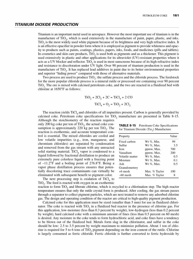
Two process are used to produce TiO2: the sulfate process and the chloride process. The feedstockfor the more popular chloride process is a mineral rutile or processed ore containing over 90 percentTiO2. The ore is mixed with calcined petroleum coke, and the two are reacted in a fluidized bed withchlorine at 1650°F as follows:
TiO2 + 2Cl2 + 2C = TiCl4 + 2 CO
TiCl4 + O2 = TiO2 + 2Cl2
The reaction yields TiCl4 and chlorides of all impurities present. Carbon is generally provided bycalcined coke. Petroleum coke specifications for TiO2 manufacture are presented in Table 8-15.Although the stoichiometry of the reaction requiresonly 200 kg coke per ton of TiO2, the actual coke con-sumption is approximately 220 kg per ton TiO2. Thereaction is exothermic, and accurate temperature con-trol is essential. The mixed chlorides are cooled andlow volatile impurities (e.g., iron, manganese, andchromium chlorides) are separated by condensationand removed from the gas stream with any unreactedsolid starting material. TiCl4 vapor is condensed to aliquid followed by fractional distillation to produce anextremely pure colorless liquid with a freezing pointof –11.2°F and a boiling point of 276.8°F. Being avapor phase distillation process ensures that poten-tially discoloring trace contaminants can virtually beeliminated with subsequent benefit to pigment color.
The next processing step is oxidation of TiCl4 toTiO2. The feed is reacted with oxygen in an exothermicreaction to form TiO2 and liberate chlorine, which is recycled to a chlorination step. The high reactortemperature ensures that only the rutile crystal form is produced. After cooling, the gas stream passesthrough a separator to collect pigment particles, which are next treated to remove any adsorbed chlorinegas. The design and operating condition of the reactor are critical to high-quality pigment production.
Calcined coke for this application must be sized (smaller than 5 mm) for use in fluidized chlori-nator. The coke is reacted with TiO2 in a fluidized bed reactor in the presence of chlorine gas. Forthis application, low-moisture (less than 0.3 percent by weight), low-hydrogen (less than 0.2 percentby weight), hard calcined coke with a minimum amount of fines (less than 0.5 percent on 60 mesh)is desired. Any moisture in the coke tends to form hydrochloric acid, and coke fines have a tendencyto be blown out of the fluidized bed. Metals form slag in the chlorinator, and sulfur in the cokeshould be low: 2.5 to 3.5 percent by weight maximum to minimize pollution. About 1 ton of chlo-rine is required for 5 to 6 tons of TiO2 pigment depending on the iron content of the rutile. Chlorineis largely consumed as ferric chloride. Ferric chloride is further converted to ferric hydroxide by
PETROLEUM COKE 161
TABLE 8-15 Petroleum Coke Specificationsfor Titanium Dioxide (Tio2) Manufacture
Property Value
Fixed carbon Wt %, Min. 99Sulfur Wt %, Max. 3.5Iron ppmw, Max. 700Vanadium ppmw, Max. 200Volatile matter Wt %, Max. 0.5Moisture Wt %, Max. 0.1Ash Wt %, Max. 0.5Granulometery+6 mesh Max. % Taylor 100–60 mesh Max. % Taylor 8

reacting with lime. Resultant calcium chloride and iron oxides are safely disposed off. About a thirdof the chlorine ends up as hydrogen chloride.
STEEL PRODUCTION
Carbon Raiser/Recarburizer: Charge Carbon
Several different types of calcined cokes are used to increase the carbon level of steel. During the purifi-cation and melting of steel (scrap iron), oxygen is injected along with lime, which reacts with impuri-ties and forms a slag on the top of molten metal. Oxygen burns the carbon in the charge, producingadditional heat in the melt. Initial charge coke added with scrap steel must have high carbon purity. Thesulfur content of the coke must be low (1 to 3 percent by weight). As the steel is further refined, lowerand lower sulfur content (less than 0.1 percent by weight sulfur) petroleum coke must be used to raisethe carbon content of the steel. Sulfur is undesirable in steel because it causes brittleness in the metal.
Injector Carbon
Injector carbon is normally sized low-sulfur petroleum coke. Sizing is necessary (less than 5 mm) toprevent plugging of the injector system. The injector is used to put carbon into melted steel belowthe foamy slag. The amount of sulfur is critical, and the amount of nitrogen in the coke can causeproblems with the heat treatment of cast steel parts. Very high temperatures during coke calciningdecrease the nitrogen content of calcined petroleum coke (CPC).
Ladle Additives
Ladle additives require carbon material with very low sulfur (less than 0.1 percent by weight), lownitrogen, and low hydrogen content. Low hydrogen in CPC is desired to prevent the hydrogen embit-terment of steel. Graphite scrap or crushed old graphite electrodes are commonly used. Coke madefrom ethylene tar is very low in sulfur and nitrogen for use as a ladle additive.
Blast Furnace Lining
Low-sulfur CPC is used for making special refractory bricks for blast furnace linings. Bricks aremade using CPC with a pitch-type binder and baked in a special pit-type furnace. The coke usedmust be low in sulfur to prevent sulfur contamination of steel.
Chemical Processing
Sized CPC with a low hydrogen content is used in the gasification process in a Stauffer-type carbonmonoxide (CO) generator for making CO. Further synthesis produces phosgene gas (COCl2) usedalong with bisphenol for production of high-strength polycarbonate plastics. Low hydrogen contentCPC is needed to prevent the formation of hydrochloric acid during the chlorination of CO.
GRAPHITE ELECTRODES
Needle coke is mainly used for the production of graphite electrodes for the steel industry. This useaccounts for almost 10 percent of the total petroleum coke produced. An electric arc furnace (EAF)is used in smaller scale steel production units using scrap steel as feed. EAFs employed in these mills
162 PETROLEUM SPECIALTY PRODUCTS

use heat generated by an electric arc to melt raw material, primarily scrap metal, and reprocess it intosteel. Graphite electrodes are a critical input into EAF steel production. Electrode consumption is ofthe order of 4 lb per ton steel. Graphite electrodes are also used in ladle furnaces for refining steeland for remelting steel in foundries. Graphite electrodes are a large column of virtually pure graphite.EAF steel production requires temperatures virtually as high as 5000°F to melt scrap metal. Heat isgenerated as electricity passes through graphite electrodes and creates an electric arc. An EAF typi-cally uses three columns of electrodes at one time. Each column typically consists of three electrodesjoined together. Graphite electrodes range in diameter from 3 to 32 in and 8 to 9 ft in length. Thetrend in EAF operations is to design an EAF with a higher electric energy input that requires largerdiameter electrodes. The larger the diameter of electrode, the more electricity it is able to conduct.A majority of electrodes sold are 28 in in diameter with a gradual shift toward larger diameters upto 32 in. Smaller ladle furnaces used for keeping steel molten use smaller diameter graphite elec-trodes. The graphite electrodes must possess a low value for the CTE because of severe thermalshocks that occur in electrical smelting. During the manufacture of these graphite electrodes, theelectrodes are heated to 3600 to 5500°F to provide energy to convert coke to crystalline graphite. Ifthe carbon feed contains any sulfur, it will decompose, causing rapid irreversible expansion of thecarbon body, thus mechanically weakening the electrode. The phenomenon is called puffing. Thusthe carbon used must have a low sulfur content. Another important property that an EAF needs ingraphite electrodes is low electrode consumption, less than 4.5 lb per ton steel produced. Theelectrode is manufactured using sized cal-cined needle coke with approximately 27percent coal tar pitch. The paste so formedis extruded so the needles in the coke are inthe direction of the extrusion. Green elec-trodes are baked and impregnated severaltimes with petroleum pitch before length-wise graphitization in a special electricallyheated furnace at 5200°F. Specifications ofneedle coke for the manufacture of large-diameter graphite electrodes are shown inTable 8-16.
Semigraphite Electrodes
Semigraphite electrodes are produced from calcined sponge coke for specialty electric furnaces suchas manufacturing phosphorus and TiO2 (sulfate process). Low sulfur (less than 1.0 percent) calcinedcoke is mixed with coal tar pitch, extruded into electrodes, and then partially graphitized.
REFERENCES
1. U.S. Patent 4043898, issued August 23, 1977.
2. U.S. Patent 4740293, “Premium Coke from a Blend of Pyrolysis Tar and Hydrotreated Decant Oil,” issuedApril 26, 1988.
3. U.S. Patent 4096097, “Method of Producing High Quality Sponge Coke or Not to Make Shot Coke,” issuedJune 20, 1978.
4. P. Rahdey, “Structural Changes in Petroleum Coke During Calcinations,” Light Metals (1967).
5. E. E. Hardin, E. C. L. Beilharz, and P. J. McCoy Lester, “A Comprehensive Review of the Effect of Calcinationsat Various Temperatures on Coke Structure and Properties When Calcined at Various Temperatures,” LightMetals (1993): 501–508.
PETROLEUM COKE 163
TABLE 8-16 Graphite Electrodes, Typical PetcokeSpecifications
Specification Units
Ash Wt % 0.2Apparent density g/cm3 1.6–1.72Porosity % 22–28Transverse strength lb/in2 1300–2000Young modulus × 106 lb/in 0.9–1.4Electrical resistance × 105 omega in 18–33CTE × 10−6 / °F 0.2–1.8
6. E. E. Hardin and R. E. Gehlbach, “Calcined Petroleum Coke for Aluminum Industry,” Great Lake CarbonCorp. information booklet, March 1992.
7. E. E. Hardin, E. C. L. Beilharz, and P. J. McCoy Lester, “A Comprehensive Review of the Effect of Calcinationsat Various Temperatures on Coke Structure and Properties When Calcined at Various Temperatures” (Part II),Light Metals (1994): 571–581.
8. P. Rhedey, “Structural Changes of Petroleum Coke During Calcinations,” Light Metals (1967).
9. P. J. Elis and J. D. Bacha, “Shot Coke,” Light Metals (1996): 477–484.
10. E. E. Hardin and R. E. Gehlbach, “Calcined Petroleum Coke for Aluminum Industry,” Great Lake Corporationinformation booklet, March 1992.
11. E. R. McHenry and Kopper Industries, Inc., “Proceeding of the Fifth Australasian Aluminum SmelterTechnology Workshop,” Sydney, Australia, October 22–27, 1995.
12. A. J. Chaudry and P. L. Singh Harihar, “Process Development for Production of Hard Pitch from Coal Tarfor Electrode Industry,” ISIJ International 39(1999): 10–14.
164 PETROLEUM SPECIALTY PRODUCTS