chapter 8. materials issues
TRANSCRIPT

Chapter 8. Materials Issuesp
29 May 2011 1

Importance of Materials
“Materials is the queen technology of any advanced technical system The economics eventually depends upontechnical system. The economics eventually depends uponthe materials, the reliability depends upon the materials,and safety depends upon the materials. I assure your thatb f th h ith f i th h i i t illbefore we are through with fusion, the physicists willgive way to the materials engineers as being the leadinglights of fusion.”
(E. E. Kintner, Head of the US Fusion Program, 1975.)
29 May 2011 2

Categories of Materials Issues
29 May 2011 3

Categories of Materials Issues
29 May 2011 4

Knock-on Atoms
N = neutronP = primary knock-on atomp yS = secondary knock-on atomI = interstitial atomV = vacancy (empty place)V = vacancy (empty place)
Displacement threshold energy = 20-60 eV
29 May 2011 5

Energy Spectra of Primary Knock-On Atoms
High-Energy Knock-On AtomsMore Damaging
1 barn = 10-28 m2
More DamagingCan cause(n,) and (n,p)
tireactions
29 May 2011 6

Damage AnalysisNeutron wall load of 1 MW/m2
4.43x10¹⁷ 14-MeV neutrons/m2sTotal neutron flux ~ 3 6x10¹⁸ /m2sTotal neutron flux ~ 3.6x10¹⁸ /m2s Neutron interactions:
(n,n’) = scattering(n,2n) = neutron multiplication(n,p) = proton emission H atoms in lattice(n,) = alpha particle emission He atoms in lattice( , ) p p(n,g) = gamma emission
Knock-on atoms become interstitials and leave vacanciesbehindbehind.
As knock-on atoms slow down, heat is generated.Short-term annealing clustering of defects.
29 May 2011 7

Types of Defect Clustersyp
Interstitial Vacancy Cavity DislocationLoop
DislocationLoop
y(3-dimensionalVacancy Cluster)Cluster)
Empty cavities shrink.Cavities filled with H2 or He gas swelling
29 May 2011 8

Computer Simulation of Radiation DamageBinary collision approximation method simulatescollisions and trajectory of knock-on atom in a lattice, including generation of secondary knock-on atoms, backscattering, etc. Not accurate at low energies.
Molecular dynamics method describes displacement cascades by integrating equations of motion for atomsi ll i i l di h li l t lin a small region, including channeling along crystalplanes. Good at low energies (< 1 keV).
29 May 2011 9

Damage Rates in Fusion Reactor MaterialsWall load = 4 43x1017 (14-MeV neutrons)/m2s = 1 MW/m2Wall load = 4.43x10 (14-MeV neutrons)/m s = 1 MW/m
(fissionreactors)
29 May 2011 10

Ratio of appm(He) to dpaFFTF = fast flux test facility (fission reactor), PNLHFIR = high flux isotopes reactor (fission reactor), ORNLRTNS-II = rotating target neutron source LLNLRTNS-II = rotating target neutron source, LLNL
(n ) reactions in Ni29 May 2011 11
(n,) reactions in Ni

Solid Transmutation Rates
29 May 2011 12

Damage Microstructure EvolutionMost interstitials become trapped in dislocationsMost interstitials become trapped in dislocations.Vacancies form voids swellingHe gas trapped in void more swellingHe trapped at grain boundaries intergranular
fracture at low strain = “helium embrittlement”
Lattice damage gradually anneals out at high T as vacancies and interstitials recombine.
High neutron fluxes (damage rate) > (annealing rate)High neutron fluxes (damage rate) > (annealing rate)
“Synergistic effect” means that the combination of twophenomena gives a result that is greater thanthe sum of their individual results.
Example: swelling (dpa+He) > swelling(dpa)+swelling(He)
29 May 2011 13
p g ( p ) g( p ) g( )

Desired First Wall Properties
29 May 2011 14

Structural Life Predictions
29 May 2011 15

Thermal StressHeat rod expansion. Compress to original length th1
Keep rod same length during heating th2
=th2 = th1
Any material with ∇T will have th, due to different thermal expansion at different T.expansion at different T. In long tube restrained at ends:
compression
r rtension
T = thermal expansion coefficient (K-1)E = Young’s modulus (Pa) = Poisson ratio = 0 25 to 0 35
29 May 2011 16
= Poisson ratio = 0.25 to 0.35

Thermal Stress
If ends are unrestrained, is 1.25 times higher thanprevious equations with r=0.
For DT: Pn = (4/5)Pf Pc = (1/5)Pf , Q = Pf/Pin
If r << r, Heat flux q/A = kT/r
q/A = (Pin + 0.2Pf)/(wall area) = (Pf/Q + 0.2Pf)/A
q/A = [ (5/4Q) + (1/4) ]Pn/A
29 May 2011 17

Thermal Stress
Example
q/A = [ (5/4Q) + (1/4) ]Pn/A q/A = 0.75 MW/m2
q/A = kT/r T = 188 K.Assume torus like long cylinder with free ends. Maximum thermal stress is ≈ 1 25 E T / 2(1 ) = 544 MPath ≈ 1.25 E T / 2(1-) = 544 MPaYield strength of annealed SS-316 = 240 MPa. Wall would fail.
29 May 2011 18

Thermal Stress ControlReduce r lower T lower thReduce q/AUse materials with higher k(1-)/EUse materials with higher k(1-)/E
If r/r << 1, ratio of yield stress to thermal stress
where
Is the “thermal stress parameter”. Large M are desirable to keep th < y.Add other stresses to find total stressAdd other stresses to find total stress.
Lifetime of SS-316 ~ 5-10 MW-a/m2
G l ll ith lif ti 40 MW / 2
29 May 2011 19
Goal = alloy with lifetime 40 MW-a/m2

Thermal Stress ParameterUnirradiated materials
29 May 2011 20

Materials TestingG f did t t i lGroups of candidate materials
Radiation source needed:Radiation source needed:> 1018 fast neutrons/m2sEnergy spectrum like that of fusion reactor
( 10 d / 100 (H )/ (H )/d 10)(~ 10 dpa/a, 100 appm(He)/a, appm(He)/dpa ~ 10)Large test volume – many specimensSurface bombardment by charged particles and x-rays
29 May 2011 21
y g p yBoth continuous and pulsed operation.

Alternative Irradiation SourcesFission reactors – lack 14-MeV neutrons
Ion bombardment – ions do not penetrate deeply,and their effects are different from neutron effects.
Neutron generators – low fluxes, small specimen volumes
29 May 2011 22

Neutron Sources
Fusion Materials Irradiation Test (FMIT) Facility was designed,but not built.
29 May 2011 23

International Fusion MaterialsInternational Fusion Materials Irradiation Facility (IFMIF)
To be discussed later
29 May 2011 24

Materials CompatibilityU d i bl h i l tiUndesirable chemical reactions:
Steel rustsLi and Na react with air or water fire hazardsStainless steel corroded by Li at T > 800 KStress accelerates corrosion by breaking
protective filmsprotective filmsSmall amounts of oxygen in He at T > 800 K attack
V and NbT i b ittl d b h dTa is embrittled by hydrogenGraphite is attacked by hydrogen to form methane
at T = 500-1200 K.Every structural material has compatibility problems
that limit allowable coolants and temperatures.
29 May 2011 25

Materials IssuesLithium can dissolve metals and deposit them
in another place. Mass transfer clogging of coolant passages,Mass transfer clogging of coolant passages,
overheating, tube failure.
Tritium permeation and trapping affects tritiumTritium permeation and trapping affects tritiuminventory safety issue.
Welds may have residual stress, impurities, embrittlement, corrosion.
Neutrons make structure radioactive remote handling,maintenance in “hot cell” needed.
29 May 2011 26

Mechanical BehaviorStress =force/(original area)Stress force/(original area)
Proportional limit
Ultimate stress
Proportional limit
At yield stressplastic deformation
Young’s Modulus
plastic deformationbegins
E = d/d(= Modulus of Elasticity)
Strain =L/Lo %
29 May 2011 27
y)

Yield Stress vs. Temperature
UnirradiatedMetals
29 May 2011 28

Irradiation Effects
At low T, defect loops, voids, and precipitates tendto increase y.
At high T y may decrease with irradiation.
Rubber band has good ductility. g yRubber band loses ductility from
cold temperatureschemicalschemicalssun’s rays.
Embrittlement caused byt t htemperature changeschemical changesradiation damage.
29 May 2011 29
g

DuctilityDuctility = percent elongation at ultimate stress
(“uniform elongation”)( g )or percent elongation at failure(“total elongation”)
Essential to prevent cracking, leakage of air,coolant, and tritium.
Need uniform elongation > 0.4%
Glass is strong and resists corrosion, but not usedfor buildings and bridges, because it lacks ductility.
29 May 2011 30

Ductilities of Unirradiated Metals
29 May 2011 31

Embrittlement of SS-304 by IrradiationIrradiated in EBR-IIat T = 640 – 740 Kand creep testedto failure at 873 K
Original ductilitywas ~ 20%.
29 May 2011 32

Radiation Hardening of Nb
Increase of u with reduction of elongation.Increase of Young’s modulus E.
29 May 2011 33

Higher Ductile-to-Brittle Transition Temperature (DBTT) Increases the Brittle Range( ) g
Steel and Mo brittle
Brittle Ductilebelow DBTT
Irradiation increases DBTT metal is brittle over wider range ofover wider range of temperatures.
DBTT i
Temperature DBTT increases with strain rate.
29 May 2011 34High temperatures may annealing

DBTT Shift of Mo-0.5%Ti
29 May 2011 35

Plastic Instability of Mo-0.5%TiBody centered cubic (bcc)Body-centered cubic (bcc) lattices may develop diamond-shaped pattern
, MPA
of channels.
After shear flow occurs, stress drops sharplystress drops sharply.
Failure at low elongation.
At high T, cavities may help prevent the plastic instability.
29 May 2011 36
p p y

Helium Embrittlement of Inconel-600, MPA(n,a) reactions He in lattice.
He grain boundariesWeakens cohesion between grainsbetween grains intergranular fracture at low elongation
Especially severe at high T.
Serious problem for Ni alloys, SS, and Al alloys.
29 May 2011 37

Helium Embrittlement
(n,) reactions generate He in lattice.
He migrates to grain boundariesWeakens cohesion between grains g
intergranular fracture at low elongation
Especially severe at high TEspecially severe at high T.
Serious problem for Ni alloys, SS, and Al alloys.
29 May 2011 38

Main Causes of Ductility Loss
primary secondaryprimary secondary
Ni alloys & SS He embrittlement radiation hardening
Aluminum alloys He embrittlement radiation hardeningAluminum alloys He embrittlement radiation hardening
Mo and W alloys DBTT shift plastic instability
Nb and Ta alloys plastic instability radiation hardening
V alloys radiation hardening He embrittlement
29 May 2011 39

FatigueRepeated stress cycles cause crack growth,gradual failure. (Railroad wheels, aircraft wings, bridges engines pressure vessels )bridges, engines, pressure vessels, …)Example: bending a piece of metal back and forth.
Pulsed magnetic fields stress cyclingPulsed plasma thermal cycling thermal stress fatigueChemical attack stress corrosion crack growthgAny repeated change of conditions (coolant flow rate,temperature, pressure, magnetic field, voltage, …)
Local stress concentrations in cracks, machining grooves,welding flaws, corrosion pits, …
29 May 2011 40

Fatigue CracksMi h t h f f ti k (C) tiMicrophotograph of fatigue cracks (C) emanatingfrom corrosion pit in low-carbon steel.
C
29 May 2011 41

Fatigue Crack Growth
Crack growth depends on
29 May 2011 42

Failure Probability vs. Number of Cycles
75S-T aluminum
Example: =300 MPa, 5x10⁴ cycles failure probability = 0.1
29 May 2011 43

Fatigue Lives vs. Strain
“Fatigue Life” = stressor strain, below whichfailure probability isvery small.
TZM=Mo with0.5% Ti, 0.08% Cr,0.03% C.
29 May 2011 44

CreepCreep = gradual increase of strain at constant stress,
especially at high temperatures (T > 0.5Tm )
Need > 104 hours (14 months) of life.
Irradiation increases the creep rate, reduces allowable .
Example: SS-316 104 hours < 160 MPaExample: SS-316 10 hours < 160 MPa.Irradiation reduces by factor of 2 < 80 MPaSafety factor of two 40 MPa design difficult.
29 May 2011 45

Time to Creep Failure
29 May 2011 46

SwellingWhen T > ¼ Tm voids can grow swelling.Swelling rate depends on
All itiAlloy compositionGrain size, precipitates, phase, cold workTemperaturepdpaappm(He)Damage rates (dpa/s)Damage rates (dpa/s)
Measured experimentally by dimension changes,d it l t imass density, electron microscopy.
Change of dimensions by 1% V/V = 3%
29 May 2011 47
g y

Volumetric Swelling vs. Temperature
Solid circles & squares:42-60 dpa, 3000-4300
20% cold-workedSS-31660 dpa, 3000 300
appm(He) in HFIR.
Open circles & squares:Open circles & squares:33-37 dpa, 15 appm(He)in EBR-II.
29 May 2011 48
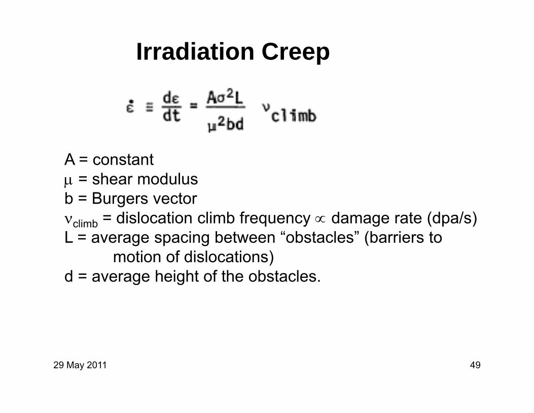
Irradiation Creep
A = constant = shear modulus = shear modulusb = Burgers vectorclimb = dislocation climb frequency damage rate (dpa/s)L i b t “ b t l ” (b i tL = average spacing between “obstacles” (barriers to
motion of dislocations)d = average height of the obstacles.g g
29 May 2011 49

Irradiation CreepNi irradiated by 4 MeV H+,40 hours at 820 K, 100 MP100 MPa
(Intense neutron sourcenot available)not available)
29 May 2011 50

Irradiation Creep
Ni irradiated by 22 MeVdeuterons or 70 MeV 2
alpha particles at 497 K, RD = 1.3-3x10⁻⁷ dpa/s.
fp accounts for the differencebetween deuterons andl h ti lalpha particles.
(Intense neutron source(not available)
29 May 2011 51

Hydrogen Isotopes Recycling
H represents H, D, or T.Reflection = backscattering of incident ion or atom.Reflection backscattering of incident ion or atom.
Spontaneous desorption. H atoms may leave surface after recombination to form Hafter recombination to form H2.
Stimulated desorption. Adsorbed H atoms ejected by incident atoms, ions, electrons, or photons.
During long plasma pulse each atom recycles from wallDuring long plasma pulse each atom recycles from wallmany times.
29 May 2011 52

Reflection from Wallwall
HFor cos distribution of incident particlesParticle reflection coefficient
rn ≈ 0.35 – 0.2 log10 0.01 < < 10
Values for normal incidence are lowerValues for normal incidence are lower, And values for isotropic distribution are higher.Values for Be are factor of 2 lower.
Linhard reduced energy:
m1, Z1 = incident particle mass, charge numberm2, Z2 = wall particle mass, charge numberW = incident particle energy or temperature (keV)
29 May 2011 53
W incident particle energy or temperature (keV)

Trapping of Deuterons in Wall
Example: Deuterons incident on Al wall with cosine distribution. What fraction are trapped in the wall?
m1 =2, m2=27, Z1=1, Z2=13, W1 = 1.
=0.841
rn ≈ 0.35 – 0.2 log10 = 0.36
Fraction trapped = 1 – rn = 0.64.
29 May 2011 54

Spontaneous Desorption
Implantation Diffusion to surface Desorption afterrecombination to H2
D ti ti diff i ti bi ti ti ( l )Desorption time = diffusion time + recombination time (slow)Spontaneous desorption flux = K c2(0,t)c = concentration of H atoms, K = recombination rate parameter.
29 May 2011 55

Energy must be supplied for hydrogen to enterendothermic metals (Al, Fe)Energy is released when hydrogen enters exothermicEnergy is released when hydrogen enters exothermicmetals (Ti, Zr)Desorption is more difficult from exothermic metals.
D = diffusion coefficientS = source from implantation(If ∇T is large, another term is needed in this equation.)E = “activation energy for diffusion”Ed = activation energy for diffusion
29 May 2011 56

Surface Recombination Coefficient
Dashed curve =Experimental values
29 May 2011 57

Stimulated DesorptionRate is proportional to incident fluxes of ions, atoms, electrons, and photons.B b d t l tti ib ti f t diff i tBombardment lattice vibrations faster diffusion to
surface. Proportional to (∂c/∂x)x=0Bombardment knocks atoms off the surface.
Proportional to c(0,t).Stimulated desorption flux =desorption flux =
= incident ion fluxi = incident ion fluxA ~ d/4= mean ion range
ff ti d ti ti 10 19 10 20 2
29 May 2011 58
d = effective desorption cross section ~ 10-19 – 10-20 m2

Stimulated DesorptionIf several monolayers of atoms were adsorbed on wall,then desorption rates would be higher.
At equilibrium flux leaving surface would equal fluxentering surface. gNumber of monolayers could be calculated from binding energies and temperature.
Recycling complicated by chemical reactions
f filsurface filmshydrogen trapping in lattice defects.
29 May 2011 59

Recycling Model Uses
Boundary conditions for plasma transport codesPl d it t l f ti f ll tiPlasma density control as function of wall preparationChange of gases in tokamaks (H D He, etc.)
(Gases coming from all dominate discharge )(Gases coming from wall dominate discharge.)Neutral gas – wall interactions in divertors, limiters,
beam dumpsbeam dumps
29 May 2011 60

Physical Sputteringincidention
ejectedwall atom
S i Yi ld S b ll j dSputtering Yield S = number wall atoms ejected perincident ion.
29 May 2011 61

Physical SputteringFor light ions at normal incidence ( = 0º )
m m = incident ion and wall atom mass numbersm1, m2 = incident ion and wall atom mass numbersE = W / WthW = ion energyWth = “threshold energy” = WB/(1-)WB = surface binding energy of wall atoms
29 May 2011 62

Sputtering Yield vs. Normalized Energy
Various wall materials
Smooth curve is equation
29 May 2011 63

Threshold Energies Wth, eV
29 May 2011 64

Sputtering Yields from Maxwellian Ions
Maxwellian
monoenergetic
29 May 2011 65

Sputtering Yields from Maxwellian IonsSBe
29 May 2011 66

Sputtering Yield vs. Angle of Incidence
29 May 2011 67

Wall Erosion RateSputtering by heavy ions or atoms high yields.
Neutrons can cause sputtering from both front and back of wall.
Wall surface erosion rate dx/dt = (1/nw) j Sj
jnw = wall atom density (m-3) = incident flux of species jj = incident flux of species jSj = sputtering yield from species j
29 May 2011 68

Example – Wall Erosion RateAn iron wall has ion fluxes of DT = 4x10¹⁹ m-2s-1 He = 3x10¹⁹ m-2s-1 andAn iron wall has ion fluxes of DT 4x10 m s , He 3x10 m s , and Fe ions = 1018 m-2s-1, with Ti = 200 eV. Estimate the wall erosion rate.
29 May 2011 69

Physichemical Sputtering
Both kinetic energy and chemical binding energy affectsputtering yield.p g y
Impact of H, C, N, O can cause chemical reactions increased sputtering yieldsincreased sputtering yields.
At low incident energies, chemical reactions alone cani H C CH tcause erosion. H + C CH4, etc.
In graphite maximum at T ~ 870 K, yieldSchem ~ 0.08 C atoms lost per H+ ion incident.chem p
29 May 2011 70

Physichemical Sputtering of Graphite
1-10 keV H+1 10 keV Honto carbon
29 May 2011 71

DesorptionAdsorbed layers on wall surface containing:C, N, H2O, O, …
Sources: gases, sputtered atoms, impurities frominside the wall materialinside the wall material.
Wall cleaning:bakeout to T > 200 C removes most monolayersbakeout to Tw > 200 C removes most monolayersplasma discharges stimulated desorptionsurface coating with boron, etc.
Impact of electrons and photons less significant than ions
29 May 2011 72

Vaporization of WallHeat of sublimation H ~ 5-10 eV
Equilibrium vapor pressureEquilibrium vapor pressurep = po exp(-H/T)
Surface evaporation fluxSurface evaporation fluxn = 2.6x1024 p/(AT)1/2 atoms/m2s ≈ 1 is sticking coefficientp = vapor pressure (Pa)A = atomic mass, g/moleT = temperature (K).T temperature (K).
Wall erosion rate dx/dt = n/nw
29 May 2011 73

Equilibrium Vapor Pressures
29 May 2011 74

Example Vaporization RateEstimate the erosion rate of a vanadium wall at 1600 Kdue to vaporization.
= 6110 kg/m3, A = 0.05094 kg/mole nw = 7.21x1028 m-3.Graph p = 1.3x10⁻⁴ Pa
n = 2.6x1024 p/(AT)1/2 = 1.2x10¹⁸ atoms/m2s
dx/dt = n/nw = 1.7x10⁻¹¹ m/s = 0.54 mm/a.
Too high need lower operating temperatureToo high, need lower operating temperature.
29 May 2011 75

Pulsed Reactor Case
Surface temperature rise from deposition of energy W:
m = mass density, cp = specific heat, k = thermal conductivity
Wall atoms evaporated per pulseWall atoms evaporated per pulsen/S = 0.1 n(Tmax) atoms/m2
29 May 2011 76

Thermal Properties of Wall Materials
29 May 2011 77

Blistering and Flaking
Irradiation by monoenergetic He+ He gas deposit atIrradiation by monoenergetic He He gas deposit ation range bubbles blistering of surface overheating rupture and wall erosion
Hydrogen can diffuse out of endothermic wall, butmay form hydrides in exothermic wall blisters
Most severe at T/Tm ~ 0.3 to 0.5.
29 May 2011 78

Blistering of Mo by He+ ions36 keV He+
T/T 0 1
T/Tm = 0.3
T/Tm = 0.1
T/T = 0 4T/Tm = 0.4 T/Tm = 0.6 porousmetal
29 May 2011 79

3.5 MeV He+ Implantation Depth
Using angulardistributiondistributioncalculatedfor tokamak
29 May 2011 80

When Blistering is a ProblemBlistering problem only if
sputtering rates lowsputtering rates lowmost He+ at 3.5 MeVHe+ flux high.
In fusion reactor blistering is inhibited byVariety of alpha energiesVariety of incident anglesSurface moving inwards by erosion, new He
implantedfurther from surfaceimplantedfurther from surface
29 May 2011 81

Unipolar ArcIf plasma > 15 V, unipolar arc can form.Anode = plasma
I hitti ll
Anode = plasmaCathode = wall.
Ions hitting wall Secondary emission + Heating Melting + Thermionic emission
I > 10 AJ ~ 109 – 1012 A/m2J 10 10 A/mJxB force moves cathode spotat 100 m/s
29 May 2011 82

Unipolar ArcMetal is melted and sprayed out. Wall loses 0.02 – 0.1 atoms per unit charge flowing.Assuming 0 05 and 30 A current 1019 atoms/s lostAssuming 0.05 and 30 A current 1019 atoms/s lost.If plasma n =3x10¹⁹ m-3 and V = 1 m3, thenImpurity fraction = 1% after 30 ms.
Scratches from unipolar arcs seen in many tokamaks,mainly during startup and disruptions.y g p p
Arcing inhibited by gas blankets and divertors.
E field at wall (nTe)1/2
29 May 2011 83

“Synergistic” EffectsNet impurity release rate > not predicted by rates of
individual phenomena rate taken separately
Examples
Physichemical sputtering > physical + chemical sputtering
Gas desorption influenced by both diffusion and surfaceGas desorption influenced by both diffusion and surfaceconditions
Photon and ion irradiation may rupture blistersPhoton and ion irradiation may rupture blisters
Blistering reduced by high sputtering rate.
29 May 2011 84

Near-Surface Wall ModificationsPhase changes -- surface films, flaking,
austenitic-martensitic transistion in SS.Alloy composition changes – nuclear transmutations,
preferential sputtering, surface segregation (Cr from SS)(Cr from SS)
Microstructural changes – vacancies, interstitials, dislocation loops internal stress, swelling,
i th t iti t icreep, grain growth, tritium trappingMacrostructural changes – surface deposits,
surface shape, crackingProperty changes – k, , emissivity, m, optical
reflectivity, radioactivity, work function, m,ductility creep rate crack growth rates
29 May 2011 85
ductility, creep rate, crack growth rates.

Wall Protection
Armor tiles – Water-cooled Cu substrate coated with C, Be, W, Mo.coated with C, Be, W, Mo.
Sputtering -- figure of merit: (critical impurity concentration for ignition)/(sputtering yield)
Good: Be BeO C B CGood: Be, BeO, C, B4C, … If Tedge low, then W is good
Blistering – porosity prevents blistering
Arcing – figure of merit:Arcing figure of merit:(critical impurity concentration for ignition)/(arcing yield)
Low-Z materials better.
29 May 2011 86
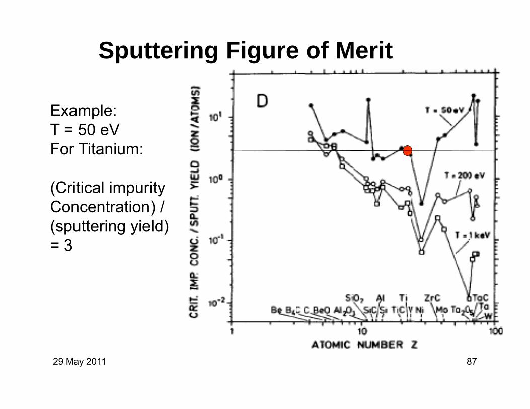
Sputtering Figure of Merit
Example:T = 50 eVT = 50 eVFor Titanium:
(Critical impurityConcentration) /(sputtering yield)(sputtering yield)= 3
29 May 2011 87

Uses of Graphite and SiC
29 May 2011 88

Radiation-Cooled Liner
29 May 2011 89

Special Purpose MaterialsGraphite and SiC
Good thermal shock resistanceNeutron reflection and moderationNeutron reflection and moderationHigh-T stabilityLow Z
Irradiation of graphite shrinks, then swellsLimited to 10-20 dpa.pGraphite fibers and clothes survived
1026 fast fission neutrons/m2
Stress limits: bulk graphite = 25 MPa, pyrolitic graphite = 250 MPa.
29 May 2011 90

Graphite Shrinkage and Swelling
Type 9640 Graphite
29 May 2011 91

Heat Sink MaterialsNeeded for limiters, wall armor, beam dumps,
calorimeters, divertor targets, direct convertors.
Need high Tm, k, cp, radiation resistance, good compatibility.p y
29 May 2011 92

Thermal Shock Limits (MW/m2)0.5 s heat pulse, 1-D heat flow
Oth d t i l T 10% W TiC TiB29 May 2011 93
Other good materials – Ta-10% W, TiC, TiB2.

Special Applications
29 May 2011 94
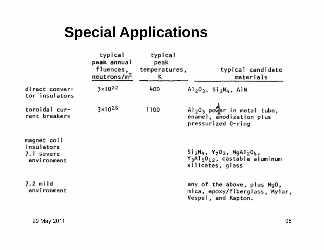
Special Applications
29 May 2011 95
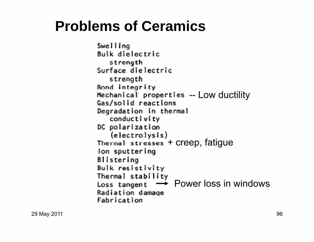
Problems of Ceramics
-- Low ductility
+ creep, fatigue
Power loss in windows
29 May 2011 96

Superconducting Magnet Materials
Nb3Sn, V3Ga, etc. B > 12 T
Radiation damage to Cu and Al increase of ,but annealing possible at T ~ 300 K.g p
Cyclic strain increases (Cu)
29 May 2011 97

Irradiation Increases Resistivity
Need to shield magnets
29 May 2011 98

Cyclic Strain Increases Resistivity
R(395 K)/R(9 K)
Copper stabilizer
29 May 2011 99

Structural MaterialsMaterials brittle at T = 4 K: many steels, Ti alloys, Mg alloys.
Weld strength and ductility reduced at low TWeld strength and ductility reduced at low T.
Composites with fibers of C, B, Kevlar-49 under study.
Magnet coil insulation – aluminumized Kapton and Mylarsuperinsulation in cryostats damaged by irradiation.
29 May 2011 100

International Fusion Materials Irradiation Facility (IFMIF) Comprehensive Design ReportFacility (IFMIF) Comprehensive Design Report
IFMIF International TeamIFMIF International Team2004
29 May 2011 101

International Fusion MaterialsIrradiation Test Facility (IFMIF)
High flux region (V=0.5 L) > 20 dpa/a
Irradiation Test Facility (IFMIF)
Medium-flux region (V=6 L) > 1 dpa/fpy Temperature control Miniaturized specimensMiniaturized specimens Post-irradiation examination (PIE)Availability > 70 %First phase: 3 years half intensityFirst phase: 3 years half-intensity
screening candidate structural materialscalibrating data from fission reactors and ion beams
Second phase: 20 years, full power test facility
29 May 2011 102

IFMIF
29 May 2011 103

Main IFMIF Parameters
2 D+ beams each 40 MeV, 125 mA Beam deposition area on target 0 2 m x 0 05 mBeam deposition area on target 0.2 m x 0.05 mJet velocity 15 m/sAverage target heat flux 1 GW/m2
Li fl t 130 l/Li flow rate 130 l/s Pressure at Li surface 10-3 Pa Hydrogen isotopes content in Li < 10 wppm y g p ppImpurity content (each C,N,O) < 10 wppm Structure SS-316 Back wall replacement period 11 monthsBack wall replacement period 11 monthsOther components lifetime 30 yearsAvailability > 95 %
29 May 2011 104

Accelerators
29 May 2011 105

Accelerators
Electron Cyclotron Resonance (ECR) ion source 95 keV 140 mA de teron beam140-mA deuteron beam.
Two Radio-Frequency-Quadrupoles (RFQ) accelerate 125 mA from 95 keV 5 MeV.
Two Alvarez Drift Tube Linacs each 124 mATwo Alvarez Drift Tube Linacs each 124 mA 5 MeV 40 MeV
Each accelerator uses 13x1 MW, 175-MHz amplifiers.
Design lifetime = 30 years.
29 May 2011 106
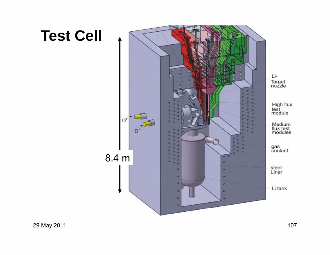
Test Cell
8.4 m
29 May 2011 107

Li Target Facility
29 May 2011 108

Lithium Temperature << Boiling
29 May 2011 109

Lithium Impurities
Major impurities = H D T C N OH, D, T, C, N, O, activated corrosion products7Be (53 day half life). ( y )
Cold trap removes most 7Be, but some will stick to tube walls.
If not removed, 7Be saturation activity = 4.5 × 10¹⁵ Bq =140 kCi.
29 May 2011 110

He Cooling of SpecimensSpecimens
29 May 2011 111

dpa Rate vs. Position High-Flux Module
29 May 2011 112

High Flux Test Module
Dimensions in mmDimensions in mm
29 May 2011 113

Specimen Holder
29 May 2011 114

High-Flux Zone Specimens
F iti t iti (ODS) t l 250 650 °C 150 d
g p
Ferritic-martensitic (ODS) steels 250-650 °C 150 dpa
Fanadium alloys: 350-650 °C 150 dpay p
SiC/SiC- composites: 600-1100 °C 150 dpa
Refractory metals (e.g. W-alloys) 650-1100 °C 80 dpa
B i t i l & j i t 650 1100 °C 80 dBrazing materials & joints 650-1100 °C 80 dpa
29 May 2011 115

High Flux Zone Tests
29 May 2011 116

Medium & Low Flux Zone Testsceramic insulators R.T-500 °C, 0.1-10 dparf-windows R.T-400 °C, 0.001-1 dpa, pceramic breeder materials 300-700 °C, 1-60 dpaneutron multipliers (Be-alloys) 300-900 °C, 1-60 dpap ( y ) , psuperconducting materials 80-100 K, <0.1 dpacreep-fatigue & crack growth testsp g gstress corrosion tests (IASCC)radiation induced electrical degradationad at o duced e ect ca deg adat otritium diffusion & release experiments
(ceramic breeders, Be-alloys)
29 May 2011 117
(ceramic breeders, Be alloys)

In-Situ Creep-Fatigue T ATest Appartus
29 May 2011 118

Safety & Environment
Remote handling – Dose rate > 105 Sv/h capabilityRemote handling Dose rate 10 Sv/h capabilityrecovery of failed equipment
Safety design fail safe fault tolerant redundantSafety – design fail-safe, fault-tolerant, redundant. Lithium fire, radioactivity release, high voltage,…
Decommissioning and Waste Disposal -- γ-surface dose rate decreases to the “hands-on level” of10 μSv/h after cooling period of 100-300 years.10 μSv/h after cooling period of 100 300 years.
29 May 2011 119

IFMIF Cost EstimatesEngineering design 88 M$ (2003)
Construction 540
Installation & testing 117Installation & testing 117
Operations 23 years 1827
Decommissioning 50
Total 2622
(Host country manages waste.)
29 May 2011 120
(Host country manages waste.)

Extra Slides
29 May 2011 121

SEMINAR – December 1、2003
Fusion Engineering Research CenterNational Institute for Fusion ScienceNational Institute for Fusion Science
Toki, Japan
Materials for New Frontiers
The Similarities andThe Similarities and Differences in Developing
Materials for Space Fission Reactors and Terrestrial Fusion
Exploring the habitable
Reactors and Terrestrial Fusion Systems
PRE-DECISIONAL - For planning and discussion purposes only
water worlds of Jupiter —Callisto, Ganymede,and Europa
F.W. Wiffen

Operating Temperature Windows for Structural Alloys in Fusion ReactorsStructural Alloys in Fusion Reactors
Ta-8W-2HfMo (TZM)
W
0.1 to 10 dpa
ODS ferritic st.V-4Cr-4Ti
Nb-1Zr-.1C
Inconel 718316 SS
F/M steel
0 200 400 600 800 1000 1200 1400SiC/SiCCuNiBe
T ( C)• Lower temperature limit of alloys based on radiation hardening/ fracture toughness embrittlement (K1C< ~30 MPa-m1/2)—large uncertainty for W,Mo due to lack of data• Upper temperature limit based on 150 MPa creep strength (1% in 1000 h); chemical
Temperature (ūC)
29 May 2011 123
compatibility considerations may cause further decreases in the max operating temp.
S.J. Zinkle and N.M. Ghoniem, Fus. Eng. Des. 51-52 (2000) 55; S.J. Zinkle et al. STAIF2002

Comparison of the Design Windows for Nb1Zr and V4Cr4Ti
150
Design Window for Nb-1Zr150
Design Window for V-4Cr-4Ti
Sm
(1/3 UTS)
100
s (M
Pa)
Sm (1/3 UTS)
100
ss (M
Pa)
radiation
50
Des
ign
Stre
ss
St (105 h, 2/3 creep rupture )radiation
embrittlement 50
Des
ign
Stre
s
St (105 h, 2/3
creep rupture )
radiation embrittlement
regime
(t>1x10²⁰ n/cm2)
0200 400 600 800 1000 1200 1400 1600
D regime (t>1x10²⁰ n/cm2)
0200 400 600 800 1000 1200 1400 1600
D
V4Cr4Ti offers ~factor of two higher stress capability than Nb1Zr
200 400 600 800 1000 1200 1400 1600Temperature (K)
200 400 600 800 1000 1200 1400 1600Temperature (K)
29 May 2011 124

29 May 2011 125

NIFS-FERC
Materials Development and Design Materials Development and Design Effort for V/Li Blanket in Japan
T. Muroga
Fusion Engineering Research Center,National Institute for Fusion Science, Japan
US/Japan Workshop on Power Plant Studies and Related Advanced Technologies
29 May 2011 126
Related Advanced TechnologiesOct. 9 and 10, UCSD

V/Li Research in JapanNIFS-FERC
Collaboration by Materials, Blanket and Design people is increasing on V/Li system in Japan
V/Li Research in Japan
people is increasing on V/Li system in Japan
Progress in the development of vanadium alloys byProgress in the development of vanadium alloys by NIFS/Universities
Enhanced development of Li technology in relation to IFMIF-Key Technology Developmentto IFMIF-Key Technology Development
Enhanced participation to ITER-TBM by NIFS/ Universities, presently V/Li is the candidate being
i d b NIFS/U i itiexamined by NIFS/UniversitiesMHD coating development needs collaboration
with design group and the collaboration is being
29 May 2011 127
g g p genhanced

Production and Characterization of High Purity V-4Cr-4Ti (NIFS-HEATs)
NIFS-FERC
NIFS-HEAT-1 has been tested by Japanese UniversitiesNIFS-HEAT-2 was distributed for international collaboration
FY1998 FY1999 FY2000 FY2001 FY2002April 98
FY2003
NIFS HEAT 2 was distributed for international collaboration
Development of high purity V
Development ofalloying method
NIFS-HEAT-1(30 kg)
MeltingShaping
Test
NIFS-HEAT-2(166 kg)
MeltingShaping
Test
10
26t 6.6t 4.0t1.9t 1.0t 0.5t 0.25t
2d
(mm)
29 May 2011 128
10 cm 2d
8d
NIFS-HEAT-2 ingots Products Specimens distributed

Merit of Purification NIFS-FERC
Some properties (welding, working, radiation response (in li it d )) i d b d ti f O d Nlimited cases)) were improved by reduction of O and N
Feasibility of economical recycling was demonstrated by reducing Al, Nb, Ag, Mo
400V-4Cr-4Ti
US-Ingot*US-Plate* Dolan, 1994
104
US832665US832864NIFS-HEAT-1NIFS-HEAT-2 Dolan, 1994
104
US832665US832864NIFS-HEAT-1NIFS-HEAT-2
educ g , b, g, o
200
300
Oxy
gen
/ wpp
m
NH2-Plate**NH1-IngotNH1-Plate**
US-V*
Quasi-Remote Recycle limit
Remote Recycle limit(remote-control reprocessing)
100
1000
Quasi-Remote Recycle limit
Remote Recycle limit(remote-control reprocessing)
Quasi-Remote Recycle limit
Remote Recycle limit(remote-control reprocessing)
100
1000
100
100 200 300 400
O
i /0
JP-V
NH2-Ingot
Hands-on Recycle limit
Quasi-Hands-on Recycle limit(contact reprocessing with some radiation control)
Element Al Nb Ag Mo
1
10
Hands-on Recycle limit
Quasi-Hands-on Recycle limit(contact reprocessing with some radiation control)Hands-on Recycle limit
Quasi-Hands-on Recycle limit(contact reprocessing with some radiation control)
Element Al Nb Ag Mo
1
10
29 May 2011 129
Nitrogen / wppm Element Al Nb Ag MoHand-onLimit (wppm) 353 0.1 0.013 10
0.1
Al Nb Ag MoElement Al Nb Ag MoHand-onLimit (wppm) 353 0.1 0.013 10
0.1
Al Nb Ag Mo

Fabrication Technology (Tubing, welding)
NIFS-FERC
Plates, wires, t bes ere
(mm)
NH2 26×26×140 mm, Pre-heating Initial pipe
Mandrel 3-directional roll
Machining
tubes were successfully fabricated
10 X 0.5t X 1004.57 X 0.25t X 400
Good property of laser-weldment
Intermediate annealing
150
200
E /
J cm
-2
EU
= 150 J cm-2Laser welding, bead-on-plate
As-weld
weldment
2TR X 180o
T = 3 mm50
100
bsob
ed e
nerg
y, E
EU
/ 2
NH2 plate
Before weldNH2 plate
29 May 2011 1301 mm 10 mm
Specimen: 50 X 8 X 3 mm
050 100 150 200 250 300 350 400
Ab
Test temperature, T / K
150 K

Creep Properties of NIFS-HEAT NIFS-FERC
One of the concerns by the purification was the creep strengthCreep strength of NIFS-HEATs was similar to other V-4Cr-4Ti
Creep RuptureCreep Rupture
NIFS HEATs
V-15Cr-5Ti
V-4Cr-4Ti
Fukumoto (ICFRM-10)F82H
T (log t + 20)
F82H
T (log t + 20)
NIFS-HEATs
Significant progress was made in developing vanadium alloys with improved engineering maturity and feasibility for
29 May 2011 131
alloys with improved engineering maturity and feasibility for economical recycling

Status of V-Alloy DevelopmentNIFS-FERC
Key-IssuesMassive production
Feasibility almost demonstrated
high puritylow activation Progress being made
Fabrication tech.Welding
but further efforts necessary for feasibility g
MHD coatingRadiation effects(He)
y
Systematic efforts
29 May 2011 132
Radiation effects(He) necessary

IFMIF Key Technology Verification NIFS-FERC
IFMIF Key Technology Verification studies were carried out in Japan in FY 2000~2002 sharing responsibilityout in Japan in FY 2000~2002, sharing responsibility by JAERI and NIFS/Universities
Li related Target research was carried out mainly NIFS/U i iti
Accelerator Target Test CellLi free surface controlImpurity/tritium control
Beam-trip suppressionRF source stability, efficiency
Specimen temperature controlSmall specimen technology
NIFS/UniversitiesIFMIF Schedule
Key Element Technology
D beam
Li flowSpecimen
Long life timeReduction of activationHigh power RFQCooling of CW‐DTL
Remote handlingy gy
Phase (KEP) 2000-2002
Transition 2003-2004
Engineering Validation and
Neutron irradiation
Heat ExchangerInjector RFQ DTL
Post-irradiation examination
Engineering Design Activity (EVEDA)
2005-2009
29 May 2011 133
EM Pump
Construction 2010~2016
Operation 2017~

Li Target Test (Osaka University) NIFS-FERC
g ( y)
A test station was installed to 200L Li loop of Osaka Univ for Target testUniv. for Target test
Free surface test successfully carried out in FY2002Li and relating device technologies were enhancedLi and relating device technologies were enhanced
1 m/s
Li
/
Li
29 May 2011 134
14 m/sExperiment Station
Horiike 2002

Li Impurity Control (U. Tokyo) NIFS-FERC
p y ( y )
V-10Ti and Cr were shown to be effective getter material for hot N traptrap
Control of N is essential for T recovery with Y T recovery study with Y in progress (U. Tokyo, Kyushu U.)
400V-10Ti]
ArAr
200
300
V 10TiCr
n in
Li [
wpp
m]
V-TiCrV-
0 100 200 300 400 500 6000
100Nitr
ogen
LiLi Mo Crucible
29 May 2011 135
Immersion time [ks]LiLi
Heater Nitrogen level in Li with Immersion Time at 823KS. Tanaka 2002

Li Loop Experiment Planned in EVEDANIFS-FERC
Full-size test loop ill b t t dwill be constructed
for validation of continuous
nozzle
Backwall( R25cm)
operationImpurity control
system will be
Li jet (20m/s)
~8m
Li monitor
system will be installed based on KEP results EM
Pump
QuenchTank
5m/s50L/s 0.3 L/s,
HNO
The technology will be applied to Li blanket
600C200C550C
Dumptank
50L/s250C
0.3 L/s,250C
~2m
O
RC
V-Ti, Cr Hot Trap for
Y Hot Trap for T
Cold Trap
29 May 2011 136
Li blanket ap oN
for T

ITER-TBM Past ProposalsNIFS-FERC
From Japan, only solid breeders were proposed to ITER via JAERIvia JAERI
A NIFS-collaboration activity started in 2002, in which liquid blanket test module is explored
Party Proposed TBM-type
JAPAN Solid - Water
Party Proposed TBM-type
JAPAN Solid - WaterJAPAN Solid Water
Solid - Helium
EU Solid - Helium
Li-Pb - Water
JAPAN Solid - Water
Solid - Helium
EU Solid - Helium
Li-Pb - Water
Russia Solid - Helium
Lithium
US Solid - He
Russia Solid - Helium
Lithium
29 May 2011 137
Lithium
1995 2001

Purpose of Li/V ITER-TBM(NIFS collaboration)
NIFS-FERC
( )
Feasibility of no-Be and natural Li blanketFeasibility of no-Be and natural Li blanketUse of 7Li reaction for enhancing TBR in contrast to
Russian Be+6Li enriched TBM
Validation of neutronics prediction Technology integration for V-alloy, Li and Tec o ogy teg at o o a oy, a d
[ Be is toxic and expensive ]
29 May 2011 138

ITER with Li/V self-cooled blanket - MCNP calculation by T. Tanaka (NIFS) -
[ I b d ] 40 cmNIFS-FERC
[ Inboard ]SS,H2O
Blanket FWVacuum
40 cm
A
Plasma
Blanket FWVacuumvessel
B
Coil
V-4Cr-4Ti walls,Natural Li
SS (60%),Li coolant (40%)
[ Outboard ]
Centersolenoid
Vacuumvessel
+ Blanket
Coilstructure
[ Outboard ]
SS,H2O
40 cm
SS,H2O
1 m
AFiller
FW Blanket Vacuumvessel
BA : Standard ITEF-FEAT blanketB ITER ith V/Li f ll bl k t
29 May 2011 139SS (60%),Li coolan (40%)
V-4Cr-4Ti walls,Natural Li(*Dimensions from ITER Nuclear Analysis Report)
Input geometry for MCNP calculation *BB : ITER with V/Li full blanket

ITER with Li/V self-cooled blanket - Local TBR -
Local TBR (Full Coverage)*
NIFS-FERC
Inboard Outboard Total Contributionof 7Li (%)
Li/V blanket 0.30 0.92 1.22 33
oca ( u Cove age)
blanket 0.30 0.92 1.22 33Coolantin filler 0.029 0.15 0.18 2.6
Total 0.33 1.1 1.4 ---
-7
5.0x10⁻⁷
Total
FP
D/cm
3)
5.0x10⁻⁷
Total
PD
/cm
3)
(* JENDL 3.2)
FW FW(a) Inboard (b) Outboard
2.0x10⁻⁷
3.0x10⁻⁷
4.0x10⁻⁷ 6Li 7Li
ction r
ate (
g/F
2 0 10-7
3.0x10⁻⁷
4.0x10⁻⁷Total
6Li 7Li
ion r
ate (
g/FP
Blanket
Fill
Blanket
330 340 350 360 370 380 390 400 4100.0
1.0x10⁻⁷
Tritium
pro
duc
840 860 880 900 920 9400.0
1.0x10⁻⁷
2.0x10 7
itiu
m p
roductiFiller
Filler
29 May 2011 140
T
Position (cm)840 860 880 900 920 940T
r
Position (cm)Distribution of tritium production rate
■ Significant contribution of 7Li to TBR

MHD Coating – Necessity–NIFS-FERC
Magnetic Field
D tMHD Pressure Drop
Duct
・Load to pumping system
・Force to structures
Li FlowForce
Insulator coating inside the
Force to structures
Pressure Drop: proportional toFlow length Velocity B2 Duct thickness Insulator coating inside the
ducts a possible solutionFlow length、Velocity、B 、Duct thickness、Conductivity of Li and Duct
29 May 2011 141

MHD Coating Candidates (1)–Free Energy
NIFS-FERC
( ) gy
St bl i i itStable ceramics in a quite reducing condition
V2O5
Selection from the free energy data
CaO、Y2O3、Er2O3、
CaZr(Sc)O3、Li2O
AlN、BN
100℃
1 10 3 2 10 3 3 10 3
29 May 2011 142
1 x 10⁻³ 2 x 10⁻³ 3 x 10⁻³
1/T(K)

MHD Coating Candidates (2)– Bulk Compatibility
NIFS-FERC
( ) p y
PotentialPotential candidatesY2O32 3
Er2O3
AlN with N control
CaZr(Sc)O3(~700C)
10m/y
(~700C)others
29 May 2011 143Japan-US JUPITER-II Collaboration (Pint, Suzuki et al. 2002)

MHD Coating DevelopmentPresent Efforts
NIFS-FERC
Development of coating t h ltechnologyRF-sputteringEB-PVDA Pl D iti 12
coatingtempdata2
RF-sputtering AlN coating (ohm*cm)RF-sputtering Y2O3 coating (ohm*cm)RF-sputtering Er2O3 coating (ohm*cm)Arc-P-Depo. Er2O3 coating (ohm*cm) by Dr. FujiwaraEB Depo. Y2O3 coating (ohm*cm) by Dr. Pint
Arc Plasma DepositionCharacterization of the
coatingResisti it
1010
1012
ResistivityHigh temperature stabilityCompatibility with LiRadiation induced
106
108
MinimumRadiation induced conductivity
In-situ coating technology104
0 200 400 600 800 1000
Temp.(C)
requirement
29 May 2011 144Japan-US JUPITER-II Collaboration (Suzuki, Pint et al. 2003)

In-situ CoatingNIFS-FERC
g
The in-situ coating method has gadvantages as,possibility of coating on the
l f ft
V-alloy Li(M)V-alloy Li(M)
complex surface after fabrication of component
potentiality to heal theCa++
O2-
Ov
Mx+
MLi
Ca++O2-
Ov
Mx+
MLi
potentiality to heal the cracks without disassembling the component
M2Ox
Mx
M2Ox
Mx
componentCaO coating has been
explored
29 May 2011 145
p

Problems of the CaO Coating and New Effort on Er2O3
NIFS-FERC
2 3
It was found that the CaO coating, after formation dissolved at highafter formation, dissolved at high temperature (600, 700C)CaO bulk is inherently not stable in
pure Li at high temperature CaOpure Li at high temperature, continuous supply of oxygen is necessary to maintain the coating
E O is m ch mo e stable at high 10m/y10m/y
CaO
Er2O3 is much more stable at high temperatureIt is expected Er2O3, once formed, be
10m/y10m/y
Er2O3
stable in Li for a long timeEr2O3 is stable in air, combination of
dry-coating and in-situ coating is
29 May 2011 146
more feasible

In-situ Er2O3 Coating on V-4Cr-4TiNIFS-FERC Er2O3 layer was formed on V-4Cr-4Ti by oxidation, anneal and exposure
to Li (Er) at 600C The coating was stable to 300 hrs
h 13 h The resistivity was ~1013 ohm-cm
Oxidation only Oxidation and anneal at
1
1.5
2x 10⁵ Er2O3-layer-0035_1.PRO
nten
sity
O1s
Er4dV2p3
1
1.5
2x 10⁵ Er2O3-layer-0030_1.PRO
nten
sity
O1sEr4d
V2p3
Oxidation at 700C
Oxidation only700C for 16 hr
~100 nmV-4Cr-4Ti
2x 10⁵ Er2O3-layer-0062_1.PRO
2x 10⁵ Er2O3-layer-0067_1.PRO
0 5 10 15 20 25 300
0.5
Sputter Time (min)
In
0 5 10 15 20 25 300
0.5
Sputter Time (min)
In6 hr
0
0.5
1
1.5
2
Inte
nsity
Er4dO1s
V2p3
0
0.5
1
1.5
2
Inte
nsity
O1sEr4dV2p3
1 hrEr
Yao. 2003
29 May 2011 147
0 5 10 15 20 25 300
Sputter Time (min)0 5 10 15 20 25 30
0
Sputter Time (min)
XPS depth profile after exposure to Li (Er) at 600C for 100 hr

Impact of Sze Summary on the Coating Development in Japan
NIFS-FERC
p p
Experimental examination of the resistance between the (flowing) Li and the wall coveredbetween the (flowing) Li and the wall covered with cracked coatings at high temperature is of high priority.g p yThe goal of the in-situ healing may be set to
increase the resistivity of cracked area from l t d ti b 4 d f it dcomplete conduction by 4 order of magnitude
Allowable crack fraction : 10(-7)Re li ti k f tion 10( 3)Realistic crack fraction : 10(-3)
Increased collaboration between materials and design people in Japan
29 May 2011 148
design people in Japan