chapter 8 - cooling considerationsmilas.spb.ru/~kmg/files/literature/power vacuum... · the...
TRANSCRIPT

Whitaker, Jerry C. “Chapter 8 – Cooling Considerations” Power Vacuum Tubes Handbook 2nd Edition.Ed. Jerry C. WhitakerBoca Raton: CRC Press LLC, 2000
© 1999 CRC Press LLC

Chapter
8Cooling Considerations
8.1 IntroductionAdequate cooling of the tube envelope and seals is one of the principal factors affect-ing vacuum tube life [1]. Deteriorating effects increase directly with the temperatureof the tube envelope and ceramic/metal seals. Inadequate cooling is almost certain toinvite premature failure of the device.
Tubes operated at VHF and above are inherently subjected to greater heating actionthan tubes operated at lower frequencies. This results directly from the following:
• The flow of larger RF charging currents into the tube capacitances at higher fre-quencies
• Increased dielectric losses at higher frequencies
• The tendency of electrons to bombard parts of the tube structure other than thenormal elements as the operating frequency is increased
Greater cooling, therefore, is required at higher frequencies. The technical data sheetfor a given tube type specifies the maximum allowable operating temperature. Forforced-air- and water-cooled tubes, the recommended amount of air or water is alsospecified in the data sheet. Both the temperature and quantity of coolant should bemeasured to be certain that cooling is adequate.
8.1.1 Thermal Properties
In the commonly used model for materials, heat is a form of energy associated withthe position and motion of the molecules, atoms, and ions of the material [2]. The po-sition is analogous with the state of the material and is potential energy, while the mo-tion of the molecules, atoms and ions is kinetic energy. Heat added to a materialmakes it hotter, and heat withdrawn from a material makes it cooler. Heat energy ismeasured in calories (cal), British Thermal Units (Btu), or joules. A calorie is theamount of energy required to raise the temperature of one gram of water one degreeCelsius (14.5 to 15.5 ºC). A Btu is the unit of energy necessary to raise the tempera-ture of one pound of water by one degree Fahrenheit. A joule is an equivalent amount
© 1999 CRC Press LLC

of energy equal to the work done when a force of one newton acts through a distanceof one meter.
Temperature is a measure of the average kinetic energy of a substance. It can also beconsidered a relative measure of the difference of the heat content between bodies.
Heat capacity is defined as the amount of heat energy required to raise the tempera-ture of one mole or atom of a material by one ºC without changing the state of the mate-rial. Thus, it is the ratio of the change in heat energy of a unit mass of a substance to itschange in temperature. The heat capacity, often referred to as thermal capacity, is acharacteristic of a material and is measured in cal/gram per ºC or Btu/lb per ºF.
Specific heat is the ratio of the heat capacity of a material to the heat capacity of areference material, usually water. Because the heat capacity of water is one Btu/lb andone cal/gram, the specific heat is numerically equal to the heat capacity.
Heat transfers through a material by conduction resulting when the energy of atomicand molecular vibrations is passed to atoms and molecules with lower energy. As heat isadded to a substance, the kinetic energy of the lattice atoms and molecules increases.This, in turn, causes an expansion of the material that is proportional to the temperaturechange, over normal temperature ranges. If a material is restrained from expanding orcontracting during heating and cooling, internal stress is established in the material.
8.1.2 Heal Transfer Mechanisms
The process of heat transfer from one point or medium to another is a result of tem-perature differences between the two. Thermal energy may be transferred by any ofthree basic modes:
• Conduction
• Convection
• Radiation
A related mode is the convection process associated with the change of phase of afluid, such as condensation or boiling. A vacuum tube amplifier or oscillator may useseveral of these mechanisms to maintain the operating temperature of the devicewithin specified limits.
Conduction
Heat transfer by conduction in solid materials occurs whenever a hotter region withmore rapidly vibrating molecules transfers a portion of its energy to a cooler regionwith less rapidly vibrating molecules. Conductive heat transfer is the most commonform of thermal exchange in electronic equipment. Thermal conductivity for solidmaterials used in electronic equipment spans a wide range of values, from excellent(high conductivity) to poor (low conductivity). Generally speaking, metals are thebest conductors of heat, whereas insulators are the poorest. Table 8.1 lists the thermalconductivity of materials commonly used in the construction (and environment) of
© 1999 CRC Press LLC

power vacuum tubes. Table 8.2 compares the thermal conductivity of various sub-stances as a percentage of the thermal conductivity of copper.
With regard to vacuum tube devices, conduction is just one of the cooling mecha-nisms involved in maintaining element temperatures within specified limits. At highpower levels, there is always a secondary mechanism that works to cool the device. Forexample, heat generated within the tube elements is carried to the cooling surfaces ofthe device by conduction. Convection or radiation then is used to remove heat from thetube itself.
Thermal conduction has been used successfully to cool vacuum tubes through directconnection of the anode to an external heat sink, but only at low power levels [1].
Table 8.2 Relative Thermal Conductivity of Various Materials As a Percentage of theThermal Conductivity of Copper
Material Relative ConductivitySilver 105Copper 100Berlox high-purity BeO 62Aluminum 55Beryllium 39Molybdenum 39Steel 9.1High-purity alumina 7.7Steatite 0.9Mica 0.18Phenolics, epoxies 0.13Fluorocarbons 0.05
Material Btu/(h·ft·°F W/(m·°CSilver 242 419Copper 228 395Gold 172 298Beryllia 140 242Phosphor bronze 30 52Glass (borosilicate) 0.67 1.67Mylar 0.11 0.19Air 0.015 0.026
Table 8.1 Thermal Conductivity of Common Materials
© 1999 CRC Press LLC

Convection
Heat transfer by natural convection occurs as a result of a change in the density of afluid (including air), which causes fluid motion. Convective heat transfer between aheated surface and the surrounding fluid is always accompanied by a mixing of fluidadjacent to the surface. Power vacuum tube devices relying on convective cooling in-variably utilize forced air or water passing through a heat-transfer element, typicallythe anode in a grid tube or the collector in a microwave tube [1]. This forced convec-tion provides for a convenient and relatively simple cooling system. In such an ar-rangement, the temperature gradient is confined to a thin layer of fluid adjacent to thesurface so that the heat flows through a relatively thin boundary layer. In the mainstream outside this layer, isothermal conditions exist.
Radiation
Cooling by radiation is a function of the transfer of energy by electromagnetic wavepropagation. The wavelengths between 0.1 and 100 m are referred to as thermal radi-ation wavelengths. The ability of a body to radiate thermal energy at any particularwavelength is a function of the body temperature and the characteristics of the surfaceof the radiating material. Figure 8.1 charts the ability to radiate energy for an ideal ra-diator, a blackbody, which, by definition, radiates the maximum amount of energy atany wavelength. Materials that act as perfect radiators are rare. Most materials radiateenergy at a fraction of the maximum possible value. The ratio of the energy radiatedby a given material to that emitted by a blackbody at the same temperature is termedemissivity. Table 8.3 lists the emissivity of various common materials.
8.1.3 The Physics of Boiling Water
The Nukiyama curve shown in Figure 8.2 charts the heat-transfer capability (mea-sured in watts per square centimeter) of a heated surface, submerged in water at vari-ous temperatures [1]. The first portion of the curve—zone A—indicates that from 100to about 108°C, heat transfer is a linear function of the temperature differential be-tween the hot surface and the water, reaching a maximum of about 5 W/cm2 at 108°C.This linear area is known as the convection cooling zone. Boiling takes place in theheated water at some point away from the surface.
From 108 to 125°C—zone B—heat transfer increases as the fourth power of ∆T un-til, at 125°C, it reaches 135 W/cm2. This zone is characterized by nucleate boiling; thatis, individual bubbles of vapor are formed at the hot surface, break away, and travel up-ward through the water to the atmosphere.
Above 125°C, an unstable portion of the Nukiyama curve is observed, where in-creasing the temperature of the heated surface actually reduces the unit thermal con-ductivity. At this area—zone C—the vapor partially insulates the heated surface fromthe water until a temperature of approximately 225°C is reached on the hot surface. Atthis point—called the Leidenfrost point—the surface becomes completely coveredwith a sheath of vapor, and all heat transfer is accomplished through this vapor cover.Thermal conductivity of only 30 W/cm2 is realized at this region.
© 1999 CRC Press LLC
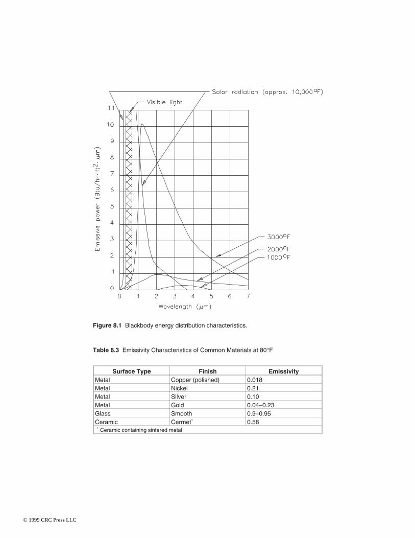
Table 8.3 Emissivity Characteristics of Common Materials at 80°F
Surface Type Finish EmissivityMetal Copper (polished) 0.018Metal Nickel 0.21Metal Silver 0.10Metal Gold 0.04–0.23Glass Smooth 0.9–0.95Ceramic Cermet1 0.58
1 Ceramic containing sintered metal
Figure 8.1 Blackbody energy distribution characteristics.
© 1999 CRC Press LLC

From the Leidenfrost point on through zone D—the film vaporization zone—heattransfer increases with temperature until at about 1000°C the value of 135 W/cm2 againis reached.
The linear plot of the Nukiyama curve indicates that zones A and B are relativelynarrow areas and that a heated surface with unlimited heat capacity will tend to passfrom zone A to zone D in a short time. This irreversible superheating is known ascalefaction. For a cylindrical vacuum tube anode, the passing into total calefaction
Figure 8.2 Nukiyama heat-transfer curves: (a) logarithmic, (b) linear.
© 1999 CRC Press LLC

would not be tolerated, because any unit heat-transfer density above 135 W/cm2 wouldresult in temperatures above 1000°C, well above the safe limits of the tube.
These properties dictate many of the physical parameters of water- and va-por-cooled power vacuum tubes. For a given dissipation, the anode structure that comesin contact with the coolant must be sufficient to keep the tube operating within the de-sired cooling zone of the Nukiyama curve and, in any event, at less than 135 W/cm2 dis-sipation on the anode structure.
8.2 Application of Cooling PrinciplesExcessive dissipation is perhaps the single greatest cause of catastrophic failure in apower tube [1]. PA tubes used in communications, industrial, and research applica-tions can be cooled using one of three methods: forced-air, liquid, and vapor-phasecooling (discussed in Chapter 3). Forced-air cooling is the simplest and most commonmethod used.
The critical points of almost every PA tube type are the metal-to-ceramic junctionsor seals. At temperatures below 250°C these seals remain secure, but above that tem-perature, the bonding in the seal may begin to disintegrate. Warping of grid structuresalso may occur at temperatures above the maximum operating level of the device. Theresult of prolonged overheating is shortened tube life or catastrophic failure. Severalprecautions usually are taken to prevent damage to tube seals under normal operatingconditions. Air directors or sections of tubing may be used to provide spot cooling atcritical surface areas of the device. Airflow sensors typically prevent operation of theRF system in the event of a cooling system failure.
Temperature control is important for vacuum tube operation because the propertiesof many of the materials used to build a tube change with increasing temperature. Insome applications, these changes are insignificant. In others, however, such changescan result in detrimental effects, leading to—in the worst case—catastrophic failure.Table 8.4 details the variation of electrical and thermal properties with temperature forvarious substances.
8.2.1 Forced-Air Cooling Systems
Air cooling is the simplest and most common method of removing waste heat from avacuum tube device [1]. The basic configuration is illustrated in Figure 8.3. The nor-mal flow of cooling air is upward, making it consistent with the normal flow of con-vection currents. In all cases, the socket is an open structure or has adequate ventholes to allow cooling of the base end of the tube. Cooling air enters at the grid circuitcompartment below the socket through a screened opening, passes through the socketto cool the base end of the tube, sweeps upward to cool the envelope, and enters theoutput circuit compartment.
The output compartment is provided with a mesh-covered opening that permits theair to vent out readily. High-power tubes typically include a chimney to direct airflow,as shown in Figure 8.4. For a forced-air design, a suitable fan or blower is used to pres-surize the compartment below the tube. No holes should be provided for the passage of
© 1999 CRC Press LLC

air from the lower to the upper compartment other than the passages through the socketand tube base. A certain amount of pressure must be built up to force the proper amountof air through the socket to cool the anode.
Attention must be given to airflow efficiency and turbulence in the design of a cool-ing system. Consider the case shown in Figure 8.5. Improper layout has resulted in inef-ficient movement of air because of circulating thermal currents. Anode cooling will beinsufficient in this case.
The cooling arrangements illustrated in Figures 8.3 and 8.4 provide for the uniformpassage of cooling air over the tube base and anode. An arrangement that forces coolingair transversely across the tube base and/or anode will not provide the same cooling ef-fectiveness and may result in hot spots on the device.
In many cases, packaged air system sockets and chimneys are designed specificallyfor a tube or family of tube types. The technical data sheet specifies the recommendedsocketing for adequate cooling. The tube data sheet also will specify the back pressure,in inches of water, and the cubic feet per minute required for adequate cooling. In an ac-tual application, the back pressure may be measured by means of a simple manometer.This device consists of a U-shaped glass tube partially filled with water, as shown inFigure 8.6.
Table 8.4 Variation of Electrical and Thermal Properties of Common Insulators As aFunction of Temperature
Parameters 20°C 120°C 260°C 400°C 538°CThermalconductivity1
99.5%BeO
140 120 65 50 40
99.5%Al2O3
20 17 12 7.5 6
95.0%Al2O3
13.5
Glass 0.3Powerdissipation2
BeO 2.4 2.1 1.1 0.9 0.7
Electricalresistivity3
BeO 1016 1014 5×10¹² 1012 1011
Al2O3 1014 1014 1012 1012 1011
Glass 1012 1010 108 106
Dielectricconstant4
BeO 6.57 6.64 6.75 6.90 7.05Al2O3 9.4 9.5 9.6 9.7 9.8
Loss tangent4 BeO 0.00044 0.00040 0.00040 0.00049 0.000801 Heat transfer in Btu/ft2/hr/°F2 Dissipation in W/cm/°C3 Resistivity in Ω-cm4 At 8.5 GHz
© 1999 CRC Press LLC

Figure 8.3 Cooling system design for a power grid tube.
Figure 8.4 The use of a chimney to improve cooling of a power grid tube.
© 1999 CRC Press LLC

Figure 8.5 A poorly designed cooling system in which circulating air in the output com-partment reduces the effectiveness of the heat-removal system.
Figure 8.6 A manometer, used to measure air pressure.
© 1999 CRC Press LLC

Cooling Airflow Data
Power tube manufacturers typically outline minimum cooling airflow requirementsfor large external-anode tubes in the form of one or more charts [1]. Figure 8.7 plotsPt /∆T as a function of Am, where Pt = total power dissipated in watts, ∆T = tube tem-perature rise in degrees Celsius, and Am = mass airflow rate in pounds of air per min-ute. This type of graph is used in calculating the cooling requirements of a vacuumtube device. The graph applies to a specified tube and socket-chimney combination;furthermore, the direction of airflow is specified. When reverse airflow (from anodeto base) is used, the cooling requirements are sharply increased because the air ap-plied to the base seals already will have been heated by its passage through the anodecooler, losing much of its cooling effectiveness.
To use the type of graph shown in Figure 8.7, first determine the minimum coolingrequirements using the following steps:
1. Calculate the total power dissipated (Pt ) by adding all of the power dissipated bythe tube during operation in a given installation. This value includes plate and fila-
Figure 8.7 Cooling airflow requirements for a power grid tube. (Data courtesy ofVarian.)
© 1999 CRC Press LLC

ment dissipations, plus maximum anticipated grid and screen dissipations (as ap-plicable).
2. Calculate the tube temperature rise (∆T) by taking the difference between themaximum rated tube temperature specified in the appropriate data sheet and themaximum expected air-inlet temperature.
3. To convert the mass airflow rate M (pounds per minute) to volumetric airflowrate Q (cubic feet per minute) at 25°C and at sea level, divide the mass airflow rateby the density of air at 25°C and 29.9 in mercury.
4. The curve on the right side of the graph is the pressure drop (∆P) in inches ofwater across the tube and its specified socket-chimney combination. This value isvalid at 25°C at sea level only.
To adjust the 25°C sea-level laboratory test conditions to any other atmospheric(socket-inlet) condition, multiply both the Q and ∆P values by the ratio of the labora-tory standard density (0.074 lb/ft3; 25°C at sea level) to the density at the new socket-in-let condition.
A shorter method may be used to approximately correct the 25°C sea level require-ments to both a different temperature and/or barometric socket-inlet condition. Thesecorrections are made by multiplying the Q and ∆P values by the appropriate correctionfactors listed in Table 8.5.
Figure 8.8 is a graph of the combined correction factors that can be applied to the25°C sea-level information for land-based installations located at elevations up to10,000 ft, and for socket-inlet air temperatures between 10 and 50°C. Figure 8.9 pro-vides a method to convert the mass airflow rate in pounds per minute into volumetricairflow rate (cfm) at 25°C and sea level.
Good engineering practice must be used when applying altitude and temperaturecorrections to the 25°C sea-level cooling requirement for airborne applications. Al-though the air outside the aircraft may be very cold at high altitudes, the air actually en-tering the tube socket may be many degrees warmer. This inlet temperature (and pres-sure) is affected by the installation design (compressed, ram, static, or recirculating airin a pressurized heat exchanger).
Blower Selection
In the previous section, a method of determining minimum air cooling requirementsfor external-anode tubes was described, pertaining to any altitude and air temperature[1]. Because most blower manufacturers furnish catalog data on their products in theform of volumetric airflow (Q, cfm) vs. operating back pressure (∆P, inches of water)for sea level conditions only, the information gained from the foregoing procedurecannot be compared directly with data furnished by manufacturers for the purpose ofselecting the proper device. The following method is recommended for use in select-ing a blower for applications above sea level from existing blower catalog data:
© 1999 CRC Press LLC

1. Determine the Q and ∆P requirements for the tube socket-chimney combinationfor an ambient air temperature of 25°C at sea level. Include the estimated ∆P ofducting and filters in the system.
2. Determine the corrected Q and ∆P system requirements for the actual inlet tem-perature and altitude conditions by multiplying by the correction factor shown inFigure 8.7.
3. Multiply the ∆P—but not the Q—requirement by the correction factor cited instep 2.
4. Use the corrected Q factor and doubly-corrected ∆P value to select a blowerfrom the manufacturer’s published sea-level curves. Although this blower willovercool the tube at sea level when operated in an ambient temperature of 25°C, itwill provide adequate cooling at the actual inlet temperature and at high-altitudeconditions.
Table 8.5 Correction Factors for Q and ∆P
Socket-Inlet Air Temperature (°C) Q and ∆P Correction Factor0 0.9175 0.93310 0.95015 0.96720 0.98325 1.00030 1.01735 1.03440 1.05145 1.06750 1.084
Socket-Inlet Air Pressure1 Altitude (ft) Q and ∆P Correction Factor29.92 0 1.0024.90 5000 1.2020.58 10,000 1.4616.89 15,000 1.7713.75 20,000 2.1711.10 25,000 2.698.89 30,000 3.377.04 35,000 4.25
1 Pressure in inches of mercury
© 1999 CRC Press LLC

8.2.2 Water Cooling
A water-cooled tube depends upon an adequate flow of fluid to remove heat from thedevice and transport it to an external heat sink [1]. The recommended flow as speci-fied in the technical data sheet should be maintained at all times when the tube is inoperation. Inadequate water flow at high temperature may cause the formation ofsteam bubbles at the anode surface where the water is in direct contact with the anode.This condition can contribute to premature tube failure.
Circulating water can remove about 1.0 kW/cm2 of effective internal-anode area. Inpractice, the temperature of water leaving the tube is limited to 70°C to preclude thepossibility of spot boiling. The water then is passed through a heat exchanger where it iscooled to 30 to 40°C before being pumped over the tube anode again.
Cooling System Design
A liquid cooling system consists of the following principal components:
• A source of coolant
• Circulation pump
Figure 8.8 Combined correction factors for land-based tube applications.
© 1999 CRC Press LLC

• Heat exchanger
• Coolant purification loop
• Various connection pipes, valves, and gauges
• Flow interlocking devices (required to ensure coolant flow anytime the equip-ment is energized)
Such a system is shown schematically in Figure 8.10. In most cases the liquid coolantwill be water, but if there is a danger of freezing, it will be necessary to use an anti-freeze solution such as ethylene glycol. In these cases, coolant flow must be increasedor plate dissipation reduced to compensate for the poorer heat capacity of the ethyleneglycol solution. A mixture of 60 percent ethylene glycol to 40 percent water by weightwill be about 75 percent as efficient as pure water at 25°C. Regardless of the choice ofliquid, the system volume must be maintained above the minimum required to ensureproper cooling of the vacuum tube(s).
The main circulation pump must be of sufficient size to ensure necessary flow andpressure as specified on the tube data sheet. Care must be taken when connecting thecoolant lines to the tube to be certain that flow is in the direction specified. Improper di-rection of flow may result in inadequate cooling as well as excessive pressure and possi-
Figure 8.9 Conversion of mass airflow rate to volumetric airflow rate.
© 1999 CRC Press LLC

ble mechanical deformation of the anode. Precautions should be taken during systemdesign to protect against water hammering of the anode. A filter screen of at least 60mesh usually is installed in the pump outlet line to trap any circulating debris that mightclog coolant passages within the tube.
The heat exchanger system is sized to maintain the outlet temperature such that theoutlet water from the tube at full plate dissipation does not exceed 70°C. Filament orgrid coolant courses may be connected in parallel or series with the main supply as longas the maximum outlet temperature is not exceeded.
Valves and pressure meters are installed on the inlet lines to the tube to permit ad-justment of flow and measurement of pressure drop, respectively. A pressure meter andcheck valve are employed in the outlet line. In addition, a flow meter—sized in accor-dance with the tube data sheet—and a thermometer are included in the outlet line ofeach coolant course. These flow meters are equipped with automatic interlockswitches, wired into the system electrical controls, so that the tube will be completelydeenergized in the event of a loss of coolant flow in any one of the coolant passages. Insome tubes, filament power alone is sufficient to damage the tube structure in the ab-sence of proper water flow.
The lines connecting the plumbing system to the inlet and outlet ports of the tube aremade of a flexible insulating material configured so as to avoid excessive strain on thetube flanges. Polypropylene tubing is the best choice for this service, but chlorinatedpolyvinyl chloride (CPVC) pipe, which is stronger, also is acceptable. Reinforced poly-
Figure 8.10 Functional schematic of a water cooling system for a high-power amplifieror oscillator.
© 1999 CRC Press LLC
propylene, such as Nylobraid, is expensive, but excellent in this application. The cool-ant lines must be of sufficient length to keep electrical leakage below 4 mA at full oper-ating power.
The hoses are coiled or otherwise supported so that they do not contact each other orany conducting surface between the high-voltage end and ground. Conducting hosebarbs, connected to ground, are provided at the low-potential end so that the insulatingcolumn of water is broken and grounded at the point where it exits the equipment cabi-net.
All metallic components within the water system, including the pump, must be ofcopper, stainless steel, or unleaded brass or bronze; copper or stainless steel is pre-ferred. If brass or bronze is used, some zinc may be leached out of the metal into the sys-tem. Any other material, such as iron or cold rolled steel, will grossly contaminate thewater.
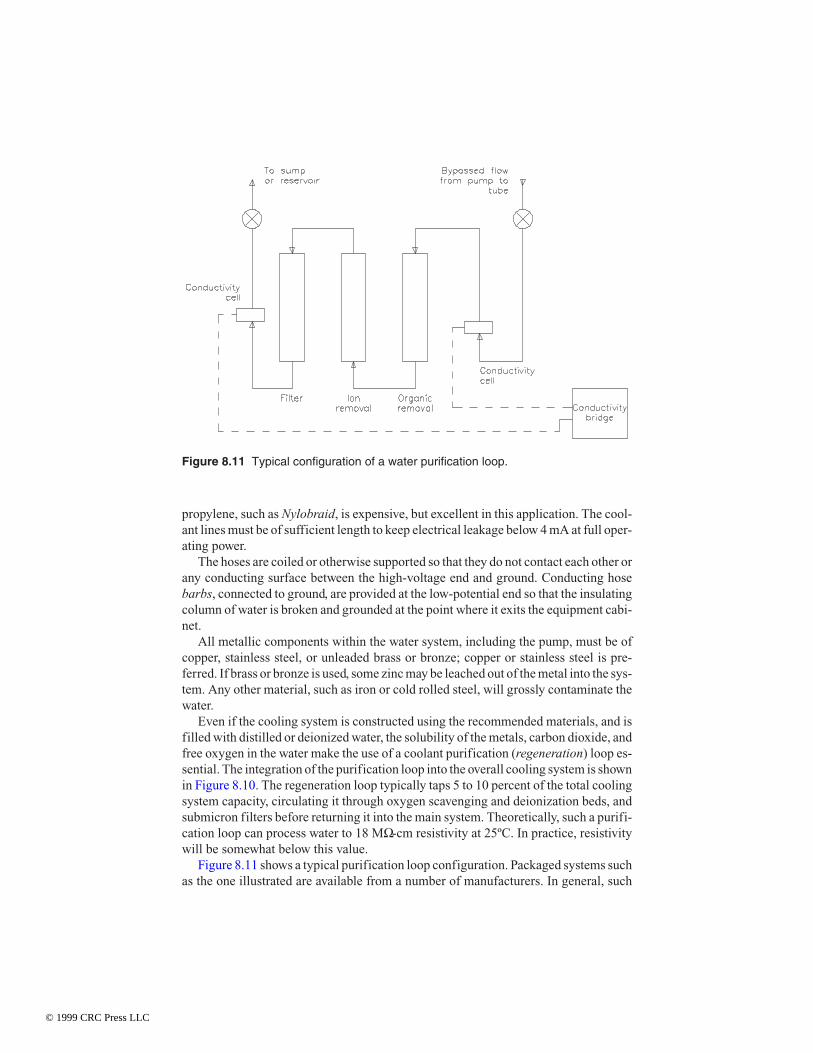
Even if the cooling system is constructed using the recommended materials, and isfilled with distilled or deionized water, the solubility of the metals, carbon dioxide, andfree oxygen in the water make the use of a coolant purification (regeneration) loop es-sential. The integration of the purification loop into the overall cooling system is shownin Figure 8.10. The regeneration loop typically taps 5 to 10 percent of the total coolingsystem capacity, circulating it through oxygen scavenging and deionization beds, andsubmicron filters before returning it into the main system. Theoretically, such a purifi-cation loop can process water to 18 MΩ-cm resistivity at 25ºC. In practice, resistivitywill be somewhat below this value.
Figure 8.11 shows a typical purification loop configuration. Packaged systems suchas the one illustrated are available from a number of manufacturers. In general, such
Figure 8.11 Typical configuration of a water purification loop.
© 1999 CRC Press LLC
systems consist of replaceable cartridges that perform the filtering, ion exchange, andorganic-solid-removal functions. The system usually will include flow and pressuregauges and valves, and conductivity cells for continuous evaluation of the condition ofthe water and filters.
Water Purity and Resistivity
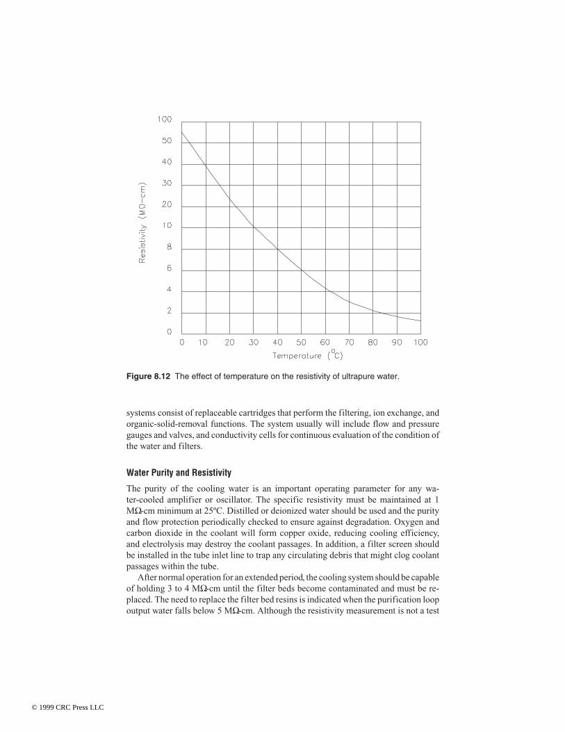
The purity of the cooling water is an important operating parameter for any wa-ter-cooled amplifier or oscillator. The specific resistivity must be maintained at 1MΩ-cm minimum at 25ºC. Distilled or deionized water should be used and the purityand flow protection periodically checked to ensure against degradation. Oxygen andcarbon dioxide in the coolant will form copper oxide, reducing cooling efficiency,and electrolysis may destroy the coolant passages. In addition, a filter screen shouldbe installed in the tube inlet line to trap any circulating debris that might clog coolantpassages within the tube.
After normal operation for an extended period, the cooling system should be capableof holding 3 to 4 MΩ-cm until the filter beds become contaminated and must be re-placed. The need to replace the filter bed resins is indicated when the purification loopoutput water falls below 5 MΩ-cm. Although the resistivity measurement is not a test
Figure 8.12 The effect of temperature on the resistivity of ultrapure water.
© 1999 CRC Press LLC
for free oxygen in the coolant, the oxygen filter bed always should be replaced when thedeionizing bed is replaced.
The resistivity of the coolant also is affected by the temperature of the water. Thetemperature-dependence of the resistivity of pure water is charted in Figure 8.12.
It is recommended that the coolant water be circulated at all times. This procedureprovides the following benefits:
• Maintains high resistivity
• Reduces bacteria growth
• Minimizes oxidation resulting from coolant stagnation
If it is undesirable to circulate the coolant at the regular rate when the tube isdeenergized, a secondary circulating pump can be used to move the coolant at a lowerrate to purge any air that might enter the system and to prevent stagnation. Recom-mended minimum circulation rates within the coolant lines are as follows:
• 2 m/s during normal operation
• 30 cm/s during standby mode
It is recommended that a circulation rate of 10 m/s be established within the tube it-self. When it is necessary to turn the coolant flow completely off, the cooling systemshould be restarted, and allowed to return to a minimum of 1 MΩ-cm resistivity beforeenergizing the tube.
The regeneration loop is typically capable of maintaining the cooling system suchthat the following maximum contaminant levels are not exceeded:
• Copper: 0.05 ppm by weight
• Oxygen: 0.5 ppm by weight
• CO2: 0.5 ppm by weight
• Total solids: 3 ppm by weight
These parameters represent maximum levels; if the precautions outlined in this sec-tion are taken, actual levels will be considerably lower.
If the cooling system water temperature is allowed to reach 50°C, it will be neces-sary to use cartridges in the coolant regeneration loop that are designed to operate at el-evated temperatures. Most ordinary cartridges will decompose in high-temperatureservice.
Condensation
The temperature of the input cooling water is an important consideration for properoperation of the cooling system [1]. If the air is humid and the cooling water is cold,condensation will accumulate on the surfaces of pipes, tube jackets, and other partscarrying water. This condensation may decrease the surface leakage resistance, ordrops of water may fall on electric components, causing erratic operation or system
© 1999 CRC Press LLC

failure. Some means is necessary, therefore, to control the temperature of the incom-ing water to keep it above the dew point. Such control is rather easy in a closed cool-ing system, but in a system that employs tap water and drains the exhaust water into asewer, control is difficult.
Preventive Maintenance
Through electrolysis and scale formation, hard water may cause a gradual constric-tion of some parts of the water system [1]. Therefore, water flow and plumbing fit-tings must be inspected regularly. The fittings on the positive-potential end of an insu-lating section of hose or ceramic water coil or column are particularly subject to cor-rosion or electrolysis unless they have protective targets. The target elements shouldbe checked periodically and replaced when they have disintegrated.
To extend the life of the resin beds in the purification loop, all the coolant linesshould be flushed with a nonsudsing detergent and a citric acid solution,1 then rinsed re-peatedly with tap water before initially connecting the resin beds and filling with dis-tilled or filtered deionized water. It is also good practice to sterilize the coolant lineswith a chlorine solution2 before filling to prevent algae and/or bacteria growth.
8.2.3 Vapor-Phase Cooling
Vapor-phase cooling offers several advantages over conventional water cooling sys-tems by exploiting the latent heat of the evaporation of water [1]. Raising the tempera-ture of 1 g of water from 40 to 70°C (as in a water system) requires 30 calories of en-ergy. Transforming 1 g of water at 100°C to steam vapor requires 540 calories. In avapor cooling system, then, a given quantity of water will remove nearly 20 times asmuch energy as in a water cooling system. Power densities as high as 135 W/cm2 ofeffective internal-anode surface can be attained through vapor cooling.
A typical vapor-phase installation consists of a tube with a specially designed anodeimmersed in a boiler filled with distilled water. When power is applied to the tube, an-ode dissipation heats the water to 100°C; further applied energy causes the water to boiland be converted into steam vapor. The vapor is passed through a condenser where itgives up its energy and is converted back into the liquid state. This condensate is thenreturned to the boiler, completing the cycle.
To achieve the most efficient heat transfer, the anode must be structured to providefor optimum contact with the water in the boiler. Figure 8.13 shows several examples.
Because the boiler usually is at a high potential relative to ground, it must be insu-lated from the rest of the system. The boiler typically is mounted on insulators, and thesteam and water connections are made through insulated tubing. High-voltage standoff
1 Cirtic acid solution mixtures vary; consult tube manufacturer.2 Chlorine solution: sodium hypochlorite bleach added in an amount sufficient to give the odor
of chlorine in the circulating water.
© 1999 CRC Press LLC

is more easily accomplished in a vapor-phase system than in a water-cooled system be-cause of the following factors:
• There is a minimum of contamination because the water is constantly beingredistilled.
• There is inherently higher resistance in the system because of the lower wa-ter-flow rate. The water inlet line is of a smaller diameter, resulting in greater re-sistance.
In a practical system, a 2-ft section of insulating tubing on the inlet and outlet ports iscapable of 20 kV standoff.
Because of the effects of thermosiphoning, natural circulation of the water elimi-nates the need for a pump in most systems.
The dramatic increase in heat absorption that results from converting hot water tosteam is repeated in reverse in the condenser. As a result, a condenser of much smallerthermal capacity is required for a vapor-phase system as opposed to a water-cooled sys-tem. For example, in a practical water-cooled system, water enters the heat exchanger at70°C and exits at 40°C; the mean temperature is 55°C. For an ambient external temper-ature of 25°C, the mean differential between the water and the heat sink (air) is 30°C.The greater the differential, the more heat transferred. In a practical va-por-phase-cooled system, water enters the heat exchanger as steam at 100°C and exitsas water at 100°C; the mean temperature is 100°C. For an ambient external temperatureof 25°C, the mean differential between the vapor/water and the heat sink is 75°C. In thisexample, the vapor-phase condenser is nearly three times more efficient than its wa-ter-cooled counterpart.
Note that the condenser in a vapor-phase system may use either air or water as a heatsink. The water-cooled condenser provides for isolation of the PA tube cooling system
Figure 8.13 Vapor-phase-cooled tubes removed from their companion boilers. (Cour-tesy of Varian/Eimac.)
© 1999 CRC Press LLC

from the outside world. This approach may be necessary because of high voltage orsafety reasons. In such a system, the water is considered a secondary coolant.
Where air-cooled condensers are preferred, the higher thermal gradient can be ex-ploited in reducing the size of condenser equipment and in lowering the blower horse-power requirement. In some instances where sufficient area is available, natural con-vection alone is used to cool the steam condensers, resulting in complete elimination ofthe condenser blower.
A typical vapor-phase cooling system is shown in Figure 8.14. It consists of the fol-lowing elements:
• Power tube
• Boiler
• Condenser
• Insulated tubing
• Control box
• Reservoir
• Associated plumbing
Anode Design
The success of vapor-phase cooling is dependent on anode and boiler designs that al-low a tube to operate at a temperature that results in maximum heat dissipation [1].
Figure 8.14 Vapor-phase cooling system for a power tube.
© 1999 CRC Press LLC
The most common approach has been to incorporate thick vertical fins on the exteriorof the anode to achieve a radial temperature gradient on the surfaces submerged inwater. In this way, a hot spot does not cause instantaneous runaway of the tube; onlythe average fin temperature increases, and this merely shifts the temperature range toa somewhat higher level. The temperatures of the fins typically vary from approxi-mately 110°C at the tip to about 180°C at the root. With an average overall fin temper-ature of approximately 115°C, for example, the average transferred heat flux is on theorder of 60 W/cm2.
When operating at low dissipation levels, boiling takes place at the root of the fin.Increasing power density causes this boiling area to move out toward the end of the finuntil, at rated dissipation levels, boiling takes place on the outer half of the fins. Gooddesign dictates that the anode fin outer edge always remain at less than 125°C.
Anode shape is also important in assuring good cooling by breaking up the sheath ofvapor that might tend to form at the surfaces. To a point, the more complicated theshape, the more efficient the anode cooler. Horizontal slots often are milled into thevertical fins to provide more area and to break up bubbles. The more vigorous the boil-ing action, the lower the possibility that an insulating vapor sheath will form. One de-sign—known as the “pineapple”—carries this idea to the extreme, and incorporatessquare “knobs” all around the anode to provide dozens of heat-radiating surfaces. Themore conventional finned anode, however, is generally adequate and less costly to fab-ricate.
The holed anode is another popular design for lower power densities (up to 100W/cm2). In this design, a heavy cylindrical anode is made with vertical holes in the out-side wall. Vapor, formed by the boiling of water within the holes, is siphoned upwardthrough the holes to the top of the boiler. This type of cooler always operates below thecalefaction point and is used in smaller tube types. The concept is illustrated in Figure8.15.
Boiler
The boiler supports the power tube and contains the water used for cooling [1]. In ad-dition, it acts as the high-voltage anode connector. The boiler should be mounted sothat the axis of the tube is vertical. For effective cooling, tilt should be limited to lessthan 2° to ensure that the anode is covered with water and that the steam outlet is clear.Figure 8.16 shows a 4CV35,000A tetrode mounted in a boiler.
The anode flange of the tube must seal securely against the O-ring provided on theboiler. A locking flange presses the anode flange against the O-ring for a vapor-tightseal. The steam outlet at the top of the steam separation chamber on the boiler and thewater inlet at the bottom of the boiler are equipped with fittings for attaching the Py-rex-insulated tubing. A target to inhibit electrolytic action is provided in the inlet waterfitting.
In most cases the boiler is at a high potential relative to ground. Therefore, it must beelectrically insulated from the rest of the system. The boiler is mounted on insulators,and the steam and water connections are made through insulating tubing. Boilers can be
© 1999 CRC Press LLC

constructed with provisions for mounting multiple tubes in parallel. In such an arrange-ment, a single water inlet and steam outlet fitting typically would be used.
Common anode/boiler hardware is well suited to RF amplifiers operating up into theHF band, which typically use conventional tuned circuits. Operation in systems athigher frequencies, however, becomes more complicated than water cooling, and cer-
Figure 8.15 Cross section of a holed anode design for vapor-phase cooling.
Figure 8.16 A 4CV35,000A tetrode mountedin its boiler assembly. (Courtesy of Varian.)
© 1999 CRC Press LLC

tainly more complicated than air cooling. The cooling system in an air-cooled RF gen-erator does not interfere with the proper operation of the cavity; it is invisible to the cav-ity. Water cooling introduces some compromises and/or adjustments in the cavity,which can be readily overcome. Vapor-cooled tubes, however, require special design at-tention for successful use.
Insulating Tubing
The length of the steam and water insulating lines varies with individual installationrequirements, but will always be shorter than would be needed in a circulating watersystem [1]. The length of the insulating tubing is determined by the following consid-erations:
• The voltage to be applied to the tube anode
• Purity of the water
• Volume of returned cooling water
Control Box
The function of the control box is to monitor and adjust the water level in the boiler[1]. A typical box is shown in Figure 8.17. The control box, an airtight vessel contain-ing an overflow siphon and two float switches, also serves as a partial reservoir. Whenthe water level drops approximately 1/4 in below the recommended level, the firstswitch is closed. This signal may be used, at the same time, to activate a solenoid-con-trolled water valve to admit more distilled water from an external reservoir; it alsomay actuate a warning alarm.
Figure 8.17 Control box for a va-por-phase cooling system. (Courtesyof Varian.)
© 1999 CRC Press LLC
The second float switch is operated if the water level drops approximately 1/2 in be-low the optimum level. This would be tantamount to a water system failure; the switchwould be used to open the control circuit interlocks and remove power from the tube.
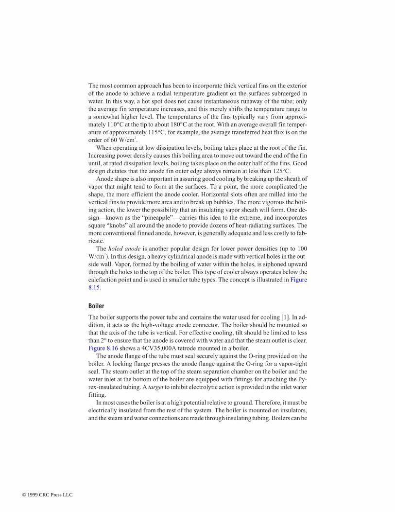
For the control box to perform its protective function properly, the water-level markmust be precisely in line with the water-level mark on the boiler. For electrical reasons,the control box generally is mounted some distance from the boiler, and therefore level-ing of the two components must be carefully checked during installation. Figure 8.18shows a cutaway drawing of a classic boiler and tube combination. Figure 8.19 is acutaway drawing of a control box, showing the position of the float switches and theoverflow pipe.
During extended operation, some quantity of water and steam being circulatedthrough the condenser will be lost. The amount is dependent on the size of the system.The water level in the boiler, therefore, will gradually drop. The use of the control boxas a reservoir minimizes this effect. In large or multiple-tube installations, an auxiliaryreservoir is connected to the control box to increase the ratio of stored water to circulat-ing water and steam. Where it may be necessary to operate multiple tubes at differentphysical elevations, individual control boxes are required. A multiple-tube system isshown in Figure 8.20.
Equalizer Line
For the control box to duplicate the same pressure conditions that exist in the boiler,the vapor-phase system must be fitted with an equalizer line [1]. This length of tubingconnects the steam side of the system with the top of the control box. As partial steam
Figure 8.18 Cutaway view of a boiler and tube combination.
© 1999 CRC Press LLC

pressure begins to build up in the boiler, the equalizer line allows this same pressureto appear in the control box. Although the steam pressure is low, less than 0.5 psiabove atmosphere, an error in the operation of the control box would be introducedunless the vessel were equalized.
The fitting used to connect the equalizer line to the steam outlet tube must be con-structed to prevent a venturi effect from developing because of the velocity of the vapor.This is best accomplished by directing an elbow within the adapter fitting toward theboiler, as shown in Figure 8.21.
Condenser
Both air-cooled and water-cooled condensers are available for vapor cooling systems[1]. Choose condensers with good reserve capabilities and low pressure drop. Air-and water-cooled condensers may be mounted in any position, provided they allowthe condensed water to flow freely by gravity to the boiler return line. Water must notbe allowed to stand in the condenser where it might cause back pressure to the enter-ing steam.
The condenser should be mounted above the level of the boiler(s) so that water willdrain from it to the boiler return line. Where it is necessary to mount the condenser at alower physical level than the system water level, an auxiliary pump must be used to re-
Figure 8.19 Cutaway view of a control box.
© 1999 CRC Press LLC

Figure 8.20 Typical four-tube vapor cooling system with a common water supply.
© 1999 C
RC
Press LL
C

turn water to the boiler. This arrangement is recommended for the “steam-out-the-bot-tom” boiler system, as illustrated in Figure 8.22.
Pressure Interlock
Most tube manufacturers recommend the use of a steam pressure interlock switch onthe steam or inlet side of the condenser [1]. This switch, set to about 0.5 lbs/in2, isused as a power interlock that senses abnormal steam pressure resulting from con-strictions in the condenser or piping.
Piping
Piping should be of copper or glass throughout the system [1]. The steam pipingshould be the same diameter as the Pyrex tube from the boiler. The size is dependenton the power level and the volume of generated steam, and it will range from 1-1/4 inat the 8 kW level to 6 in for the 250 kW level of dissipation. The steam path should beas direct as practical and must be sloped to prevent condensate from collecting at alow point where it might cause back pressure. All low spots should be drained back tothe inlet water line.
The diameter of water return piping from the condenser to the control box will varyfrom 3/4 to 1-3/4 in, depending again on the power level. This tubing should be thesame diameter as the boiler inlet water fitting. It also should be sloped so that water orvapor pockets are not allowed to form, and it must allow the condensate to return bygravity to the control box and the boiler. A vent to air on the outlet side of the condensershould be incorporated to maintain the water side of the system at atmospheric pres-sure. Provisions for draining the distilled water should be made at the lowest physicallevel of the system.
Figure 8.21 Cutaway view of a pressureequalizer fitting.
© 1999 CRC Press LLC

Figure 8.22 Typical four-tube vapor cooling system using “steam-out-the-bottom” boilers.
© 1999 C
RC
Press LL
C

The equalizer line also should be sloped from the adapter fitting on the steam line tothe top of the control box. This will allow the condensate to return to the control box.
Automatic Refilling System
Figure 8.23 shows a typical vapor cooling system with provisions to allow additionalwater into the control box [1]. An auxiliary reservoir is connected through a sole-noid-operated water valve to the controller. When water loss resulting from evapora-tion causes the water level in the boiler and the control box to drop about 1
4 in belownormal, the first float switch in the control box closes and actuates the solenoid-con-trolled valve to permit makeup water to enter the system. When the proper level is re-stored, the switch opens, the valve closes, and the flow of makeup water is stopped.
Alternative Vapor Cooling Systems
The systems described thus far are “classic” designs in which a separate tube, boiler,condenser, and level control box are used [1]. Variations on this basic scheme are nu-merous. One such alternative system, offered for use with large power tubes, utilizes a“steam-out-the-bottom” boiler. This configuration makes it possible to keep thesteam and water systems, plus the plumbing, below the tubes. This configuration of-ten simplifies the electrical design of the amplifier or oscillator. Figure 8.24 shows atypical boiler used in this cooling technique.
A small water pump circulates a continuous flow of water over a weir—or baffle—inthe boiler, maintaining a constant water level. Generated steam is forced under slight
Figure 8.23 Vapor cooling system incorporating a reservoir of distilled water.
© 1999 CRC Press LLC

pressure out the bottom of the boiler, through an insulator tube in the condenser. Waterfrom the condenser flows into the control box before being pumped back into the boiler.Protective devices include a water-flow interlock and water-level switch in the controlbox to ensure an adequate supply of coolant.
Maintenance
Maintenance problems associated with circulating water systems are practically elim-inated in a vapor cooling system [1]. As mentioned previously, systems can be de-signed to eliminate all rotating machinery or moving parts. Good engineering practicedoes, however, dictate periodic maintenance. The glass insulator tubes should be in-spected occasionally to be sure they contain no deposits that might cause high-voltageflashover. Water conductivity can be checked by measuring the dc resistance, as in atypical circulating water system. The water should be replaced if the dc resistancedrops below 1.0 MΩ-cm.
In practice, a vapor-cooled system will remain cleaner longer than a water-cooledsystem. In the vapor-cooled boiler, the water is continuously being redistilled, and onlypure water is introduced at the bottom of the boiler. Any contaminants will tend to re-main in the boiler itself, where they can be removed easily. The periods between equip-ment shutdown for draining and cleaning will be at least twice as long for a vapor cool-ing system because of this inherent self-cleaning action.
Each time a tube is removed or replaced, the rubber O-ring between the boiler andthe tube should be inspected and, if necessary, replaced. At the same time, the inside ofthe boiler and the control box can be inspected and cleaned as needed. The electrolytic
Figure 8.24 Cutaway view of a “steam-out-the-bottom” boiler.
© 1999 CRC Press LLC
target should be replaced whenever its metallic end is no longer visible in the inlet wa-ter line.
8.2.4 Temperature Measurements
Before completing any design employing power tubes, check temperatures in criticalareas, such as metal/ceramic seals and (except for water- and vapor-cooled types) theanode just above and below the cooling fins [1]. Another critical area on many me-dium and large tubes of coaxial design is the central part of the base, which is often re-cessed and may need special cooling provisions. Electrical contact to the tube termi-nals is usually by copper-beryllium collets, which should not exceed a temperature of150°C for any extended period of time. A number of manufacturers make tempera-ture-sensitive paints that are useful for such measurements.3 “Crayon-type” indicatorsare also available, in a wide range of temperatures. Conventional temperature measur-ing-techniques may be affected by the radio frequency energy concentrated at the tubeand nearby components. Furthermore, because all power tubes operate at high volt-age, there is danger of electric shock with directly connected devices.
When a temperature-sensitive paint or crayon is used for measurement, it must beremembered that many of the areas of concern are vacuum seals involving relativelythin metal. It is important, therefore, that the indicator material be noncorrosive.
Considering the importance of tube element temperatures, every design must beevaluated carefully. All power tubes carry an absolute maximum temperature rating forthe seals and envelope, and in the case of an external-anode forced-air-cooled tube, forthe anode core itself. Operation above the rated maximum can cause early tube failure.Where long life and consistent performance are important factors, it is normally desir-able to maintain tube temperatures comfortably below the rated maximum.
The equipment operator has the ultimate responsibility of making sure that thepower tubes used in the system are operating within specified ratings. Most currenttube designs use a ceramic envelope and an externally mounted anode or collector. Theonly visible sign of excessive temperature may be the cosmetic plating beginning todarken or turn black (oxidize). By then, significant damage may have occurred.
“Crayon” Temperature Measurement
When a crystalline solid is heated, a temperature will be reached at which the solidchanges sharply to a liquid [1]. This melting point has a definite, reproducible valuethat is virtually unaffected by ambient conditions that may cause errors in other tem-perature-sensing methods. For example, fusible temperature indicators are practicalin induction heating and in the presence of static electricity or ionized air around elec-tric equipment, where electronic means of measuring temperatures often function er-ratically.
3 Tempilaq is one such product (Tempil Division, Big Three Industrial Gas and EquipmentCo., South Plainfield, NJ).
© 1999 CRC Press LLC

The most popular type of fusible indicator is a temperature-sensitive stick closelyresembling a crayon, with a calibrated melting point. These crayon-type indicators aremade in 100 or so different specified temperature ratings in the range of 100 to 2500°F.Typically, each crayon has a temperature-indicating accuracy within 1 percent of its rat-ing. The workpiece to be tested is marked with the crayon. When the workpiece attainsthe predetermined melting point of the crayon, the mark instantly changes from a solidto a liquid phase (liquefies), indicating that the workpiece has reached that tempera-ture.
Under certain circumstances, premarking with crayon is not practical. This is thecase if one or more of the following is true:
• A prolonged heating period is experienced.
• The surface is highly polished and does not readily accept a crayon mark.
• The material being marked is one that gradually absorbs the liquid phase of thecrayon.
Note that a melted mark, upon cooling, will not solidify at the exact temperature atwhich it melted. Solidification of a melted crayon mark, therefore, cannot be relied onfor exact temperature indication.
Phase-Change Fluid
A phase-changing fluid, or fusible temperature-indicating lacquer, offers the greatestflexibility in temperature measurement of a power tube [1]. The lacquer-type fluidcontains a solid material of calibrated melting point suspended in an inert, volatile,nonflammable vehicle. As with crayon-type indicators, there are approximately 100different temperature ratings, covering a range from 100 to 2500°F. Accuracy is typi-cally within 1 percent of the specified value.
The lacquer is supplied in the proper consistency for brushing. If spraying or dip-ping is desirable as the mode of application, a thinner is available to alter the viscositywithout impairing the temperature-indicating accuracy.
Phase-changing lacquers often are used when a smooth or soft surface must betested, or in situations where the surface is not readily accessible for application of acrayon mark during the heating process. Within seconds after application, the lacquerdries to a dull matte finish, and it responds rapidly when the temperature to be indicatedis reached. The response delay of a lacquer mark is only a fraction of a second. Thistime can be reduced to milliseconds if a mark of minimal thickness is applied.
Upon reaching its rated temperature, the lacquer mark will liquefy. On subsequentcooling, however, the fluid will not revert to its original unmelted appearance but,rather, to a glossy or crystalline coating, which is evidence of its having reached the re-quired temperature. Temperature-indicating lacquers, upon cooling, will not resolidifyat the same temperature at which they melted.
If spraying of the phase-change lacquer is to be the sole means of application, the op-erator may find it more convenient to use an aerosol-packaged form of this material. An
© 1999 CRC Press LLC
aerosol phase-change temperature indicator is identical to the brush-on material in per-formance and interpretation.
The first commercial form of the fusible indicator was the pellet, which continues tobe useful in certain applications. Pellets are most frequently employed when extendedheating periods are involved, or where a greater bulk of indicator material is necessary.They are also useful when observations must be made from a distance and whenair-space temperatures are to be monitored.
Phase-change temperature-indicator pellets are available in flat, 7/16-in-diameter ×1/8-in-thick tablets. For special applications, miniature pellets, 1/8 in × 1/8 in, are alsoavailable. The range of 100 to 2500°F covered by the crayon and lacquer-type is, like-wise, covered by the pellets. Pellets with coverage extending to 3200°F also may be ob-tained.
Another variation of the phase-change indicator is the temperature-sensitive label.4
These self-adhesive-backed monitors consist of one or more heat-sensitive indicatorssealed under transparent heat-resistant windows. The centers of the indicator circlesturn from white to black at the temperature ratings shown on the label. The change toblack is irreversible, representing an absorption of the temperature-sensitive substanceinto its backing material. After registering the temperature history of the workpiece, theexposed monitor label can be removed and affixed to a service report to remain part of apermanent record.
Selection Process
Fusible temperature indicators and lacquers have at least three major advantages overother methods of determining surface temperature [1]:
• The temperature indications obtained are unquestionably those of the surface be-ing tested. It is not necessary to equilibrate a relatively massive probe with thesurface (a probe may conduct heat away from the region being tested), which re-quires the use of a correction factor to obtain the actual surface temperature.
• There is no delay in obtaining an indication. Because a mark left by a crayon or alacquer is of extremely small mass, it attains rapid equilibrium with the surface.There is no conduction of heat away from the surface, which would prolong re-sponse time and result in erroneously low temperature readings.
• The technique is simple and economical. Determination of surface temperatureby most other means requires technical competence and skill and, in some cases,sophisticated instrumentation. Accurate surface temperature readings can be ob-tained with fusible indicators and lacquers with little effort, training, and ex-pense.
4 Temp-Plate is one such product (Williams-Wahl Corp., Santa Monica, CA).
© 1999 CRC Press LLC
There are numerous instances, particularly in determining heat distribution in com-plex systems, in which the relative simplicity of fusible indicators and lacquers makessurface temperature investigations feasible.
8.2.5 Air-Handling System
All modern air-cooled PA tubes use an air-system socket and matching chimney forcooling [1]. The chimney is designed to be an integral part of the tube cooling system.Operation without the chimney may significantly reduce airflow through the tube andresult in overdissipation of the device. It also is possible that operation without theproper chimney could damage other components in the circuit because of excessiveradiated heat. Normally, the tube socket is mounted in a pressurized compartment sothat cooling air passes through the socket and is guided to the anode cooling fins, asillustrated in Figure 8.25.
Cooling of the socket assembly is important for proper cooling of the tube base andfor cooling the contact rings of the tube itself. The contact fingers used in the collet as-sembly of a socket typically are made of beryllium copper. If subjected to temperaturesabove 150°C for an extended period of time, the beryllium copper will lose its temper(springy characteristic) and will no longer make good contact with the base rings of thedevice. In extreme cases, this type of socket problem may lead to arcing, which canburn through the metal portion of the tube base ring. Such an occurrence ultimatelymay lead to catastrophic failure of the device because of a loss of the vacuum envelope.Other failure modes for a tube socket include arcing between the collet and tube ring,which can weld a part of the socket and tube together. The result is failure of both thetube and the socket.
8.3 Operating EnvironmentLong-term reliability of a power vacuum tube requires regular attention to the operat-ing environment. Periodic tests and preventive maintenance are important compo-nents of this effort. Optimum performance of the cooling system can be achieved onlywhen all elements of the system are functioning properly.
8.3.1 Air-Handling System
The temperature of the intake air supply is a parameter that is usually under the con-trol of the end user. The preferred cooling air temperature is typically no higher than75°F, and no lower than the room dew point. The air temperature should not vary be-cause of an oversized air-conditioning system or because of the operation of otherpieces of equipment at the facility. Monitoring the PA tube exhaust stack temperatureis an effective method of evaluating overall RF system performance. This can be eas-ily accomplished. It also provides valuable data on the cooling system and final stagetuning.
Another convenient method for checking the efficiency of the transmitter coolingsystem over a period of time involves documenting the back pressure that exists within
© 1999 CRC Press LLC

the PA cavity. This measurement is made with a manometer, a simple device that isavailable from most heating, ventilation, and air-conditioning (HVAC) suppliers. Theconnection of a simplified manometer to a transmitter PA output compartment is illus-trated in Figure 8.26.
By charting the manometer readings, it is possible to accurately measure the perfor-mance of the transmitter cooling system over time. Changes resulting from the buildupof small dust particles (microdust) may be too gradual to be detected except throughback-pressure charting. Deviations from the typical back-pressure value, either higheror lower, could signal a problem with the air-handling system. Decreased PA input oroutput compartment back pressure could indicate a problem with the blower motor oran accumulation of dust and dirt on the blades of the blower assembly. Increased backpressure, on the other hand, could indicate dirty PA tube anode cooling fins (for the in-put compartment case) or a buildup of dirt on the PA exhaust ducting (for the outputcompartment case). Either condition is cause for concern. A system suffering from re-
Figure 8.25 Airflow system for an air-cooled power tube.
© 1999 CRC Press LLC

duced air pressure into the PA compartment must be serviced as soon as possible. Fail-ure to restore the cooling system to proper operation may lead to premature failure ofthe PA tube or other components in the input or output compartments. Cooling prob-lems do not improve with time; they always get worse.
Failure of the PA compartment air-interlock switch to close reliably may be an earlyindication of impending trouble in the cooling system. This situation could be causedby normal mechanical wear or vibration of the switch assembly, or it may signal that thePA compartment air pressure has dropped. In such a case, documentation of manome-ter readings will show whether the trouble is caused by a failure of the air pressureswitch or a decrease in the output of the air-handling system.
Figure 8.26 A manometer device used for measuring back pressure in the PA compart-ment of an RF generator.
© 1999 CRC Press LLC

8.3.2 Air Cooling System Design
Cooling system performance in an RF generator is not necessarily related to airflowvolume. The cooling capability of air is a function of its mass, not its volume. The de-signer must determine an appropriate airflow rate within the equipment and establishthe resulting resistance to air movement. A specified static pressure that should bepresent within the ducting of the transmitter can be a measure of airflow. For anygiven combination of ducting, filters, heat sinks, RFI honeycomb shielding, tubes,tube sockets, and other elements in the transmitter, a specified system resistance toairflow can be determined. It is important to realize that any changes in the position ornumber of restricting elements within the system will change the system resistanceand, therefore, the effectiveness of the cooling. The altitude of operation is also a con-sideration in cooling system design. As altitude increases, the density (and coolingcapability) of air decreases. A calculated increase in airflow is required to maintainthe cooling effectiveness that the system was designed to achieve.
Figure 8.27 shows a typical high-power transmitter plant. The building is oriented sothat the cooling activity of the blowers is aided by normal wind currents during the sum-mer months. Air brought in from the outside for cooling is filtered in a hooded air-in-take assembly. The building includes a heater and air conditioner.
Figure 8.27 A typical heating and cooling arrangement for a high-power transmitter in-stallation. Ducting of PA exhaust air should be arranged so that it offers minimum resis-tance to airflow.
© 1999 CRC Press LLC

The layout of a transmitter room HVAC system can have a significant impact on thelife of the PA tube(s) and the ultimate reliability of the RF generator. Air intake and out-put ports must be designed with care to avoid airflow restrictions and back-pressureproblems. This process, however, is not as easy as it may seem. The science of airflow iscomplex and generally requires the advice of a qualified HVAC consultant.
To help illustrate the importance of proper cooling system design and the real-worldproblems that some facilities have experienced, consider the following examples takenfrom actual case histories:
Case 1
A fully automatic building ventilation system (Figure 8.28) was installed to maintainroom temperature at 20°C during the fall, winter, and spring. During the summer,however, ambient room temperature would increase to as much as 60°C. A field sur-vey showed that the only building exhaust route was through the transmitter. There-fore, air entering the room was heated by test equipment, people, solar radiation onthe building, and radiation from the transmitter itself before entering the transmitter.The problem was solved through the addition of an exhaust fan (3000 cfm). The 1 hpfan lowered room temperature by 20°C.
Case 2
A simple remote installation was constructed with a heat-recirculating feature for thewinter (Figure 8.29). Outside supply air was drawn by the transmitter cooling systemblowers through a bank of air filters, and hot air was exhausted through the roof. A
Figure 8.28 Case study in which excessive summertime heating was eliminatedthrough the addition of a 1 hp exhaust blower to the building.
© 1999 CRC Press LLC
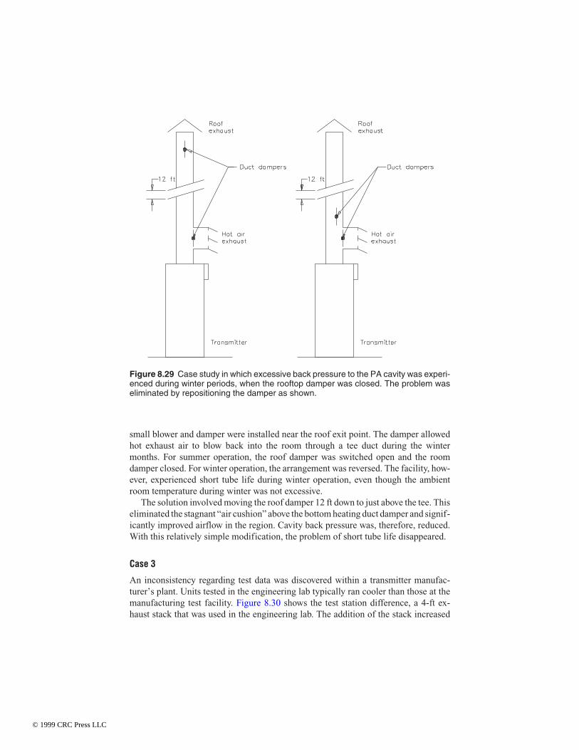
small blower and damper were installed near the roof exit point. The damper allowedhot exhaust air to blow back into the room through a tee duct during the wintermonths. For summer operation, the roof damper was switched open and the roomdamper closed. For winter operation, the arrangement was reversed. The facility, how-ever, experienced short tube life during winter operation, even though the ambientroom temperature during winter was not excessive.
The solution involved moving the roof damper 12 ft down to just above the tee. Thiseliminated the stagnant “air cushion” above the bottom heating duct damper and signif-icantly improved airflow in the region. Cavity back pressure was, therefore, reduced.With this relatively simple modification, the problem of short tube life disappeared.
Case 3
An inconsistency regarding test data was discovered within a transmitter manufac-turer’s plant. Units tested in the engineering lab typically ran cooler than those at themanufacturing test facility. Figure 8.30 shows the test station difference, a 4-ft ex-haust stack that was used in the engineering lab. The addition of the stack increased
Figure 8.29 Case study in which excessive back pressure to the PA cavity was experi-enced during winter periods, when the rooftop damper was closed. The problem waseliminated by repositioning the damper as shown.
© 1999 CRC Press LLC

airflow by up to 20 percent because of reduced air turbulence at the output port, re-sulting in a 20°C decrease in tube temperature.
These examples point out how easily a cooling problem can be caused during HVACsystem design. All power delivered to the transmitter either is converted to RF energyand sent to the antenna or becomes heated air (or water). Proper design of a cooling sys-tem, therefore, is a part of transmitter installation that should not be taken lightly.
8.3.3 Site Design Guidelines
There are any number of physical plant designs that will provide for reliable operationof high-power RF systems [3]. One constant, however, is the requirement for tighttemperature control. Cooling designs can be divided into three broad classifications:
• Closed site design
• Open site design
• Hybrid design
If the equipment user is to provide adequately for hot air exhaust and fresh air intake,the maximum and minimum environmental conditions in which the equipment will op-
Figure 8.30 Case study in which air turbulence at the exhaust duct resulted in reducedairflow through the PA compartment. The problem was eliminated by adding a 4-ft ex-tension to the output duct.
© 1999 CRC Press LLC

erate must be known. In addition, the minimum cooling requirements of the equipmentmust be provided by the manufacturer. The following parameters should be considered:
• Site altitude
• Maximum expected outside air temperature
• Minimum expected outside air temperature
• Total airflow through the transmitter
• Air temperature rise through the transmitter
• Air exhaust area
Keep in mind that the recommended cooling capacity for a given RF system appliesonly to cooling the transmitter; any additional cooling load in the building must be con-sidered separately when selecting the air system components. The transmitter exhaustshould not be the only exhaust port in the room because heat from the peripheral equip-ment would then be forced to go out through the transmitter.
The sensible-heat load, then, is the sum of all additional heat loads, including:
• Solar radiation
• Heat gains from equipment and lights
• Heat gains from personnel in the area that is to be cooled
Closed Site Design
Figure 8.31 illustrates a site layout that works well in most climates, as long as thetransmitter is small and the building is sealed and well insulated [3]. In fact, thisclosed configuration will ensure the longest possible transmitter life and lowest main-tenance cost. No outside air laden with moisture and contaminants circulates throughthe transmitter.
At sites using this arrangement, it has been observed that periodic transmitter clean-ing is seldom required. In a typical closed system, the air conditioner is set to cool whenthe room temperature reaches 75 to 80°F. The closed system also uses a louvered emer-gency intake blower, which is set by its own thermostat to pull in outside air if the roomtemperature reaches excessive levels (above 90°F). This blower is required in a closedconfiguration to prevent the possibility of thermal runaway if the air conditioner fails.Without such an emergency ventilation system, the transmitter would recirculate itsown heated air, further heating the room. System failure probably would result.
During winter months, the closed system is self-heating (unless the climate is harsh,or the transmitter power output is low), because the transmitter exhaust is not ductedoutside but simply empties into the room. Also during these months, the emergency in-take blower can be used to draw cold outside air into the room instead of using the airconditioner, although this negates some of the cleanliness advantages inherent to theclosed system.
© 1999 CRC Press LLC

An exhaust blower should not be substituted for an intake blower, because positiveroom pressure is desired for venting the room. This ensures that all air in the buildinghas passed through the intake air filter. Furthermore, the louvered emergency exhaustvent(s) should be mounted high in the room, so that hot air is pushed out of the buildingfirst.
The closed system usually makes economic sense only if the transmitter exhaustheat load is relatively small.
Periodic maintenance of a closed system involves the following activities:
• Checking and changing the air conditioner filter periodically
• Cleaning the transmitter air filter as needed
• Checking that the emergency vent system works properly
• Keeping the building sealed from insects and rodents
Open Site Design
Figure 8.32 depicts a site layout that is the most economical to construct and operate[3]. The main attribute of this approach is that the transmitter air supply is not heatedor cooled, resulting in cost savings. This is not a closed system; outdoor air is pumpedinto the transmitter room through air filters. The transmitter then exhausts the hot air.If the duct work is kept simple and the transmitter has a dedicated exhaust port, such adirect exhaust system works adequately. Many transmitters do not lend themselves to
Figure 8.31 Closed site ventilation design, with a backup inlet/outlet system.
© 1999 CRC Press LLC

a direct exhaust connection, however, and a hood mounted over the transmitter may berequired to collect the hot air, as illustrated in Figure 8.33. With a hooded arrange-ment, it may be necessary to install a booster fan in the system, typically at the wall orroof exit, to avoid excessive back pressure.
When building an open air-circulation system, there are some important additionalconsiderations. The room must be positively pressurized so that only filtered air, whichhas come through the intake blower and filter, is available to the transmitter. With a neg-atively pressurized room, air will enter through every hole and crack in the building,and will not necessarily be filtered. Under negative pressure, the transmitter bloweralso will have to work harder to exhaust air.
The intake blower should be a “squirrel-cage” type rather than a fan type. A fan ismeant to move air within a pressurized environment; it cannot compress the air. Asquirrel-cage blower will not only move air, but also will pressurize the area into whichthe air is directed. Furthermore, the intake air blower must be rated for more cubic feetper minute (cfm) airflow than the transmitter will exhaust outside. A typical 20 kW FMbroadcast transmitter, for example, will exhaust 500 cfm to 1000 cfm. A blower of 1200cfm, therefore, would be an appropriate size to replenish the transmitter exhaust andpositively pressurize the room.
In moderate and warm climates, the intake blower should be located on a north-fac-ing outside wall. If the air intake is on the roof, it should be elevated so that it does notpick up air heated by the roof surface.
Figure 8.32 Open site ventilation design, using no air conditioner.
© 1999 CRC Press LLC

High-quality pleated air filters are recommended. Home-style fiberglass filters arenot sufficient. Local conditions may warrant using a double filtration system, withcoarse and fine filters in series.
Secure the advice of a knowledgeable HVAC shop when designing filter boxes. Fora given cfm requirement, the larger the filtration area, the lower the required air velocitythrough the filters. This lower velocity results in better filtration than forcing more airthrough a small filter. In addition, the filters will last longer. Good commercial filtra-tion blowers designed for outdoor installation are available from industrial supplyhouses and are readily adapted to RF facility use.
The transmitter exhaust may be ducted through a nearby wall or through the roof.Avoid ducting straight up, however. Many facilities have suffered water damage totransmitters in such cases because of the inevitable deterioration of roofing materials.Normally, ducting the exhaust through an outside wall is acceptable. The duct worktypically is bent downward a foot or two outside the building to keep direct wind fromcreating back pressure in the exhaust duct. Minimize all bends in the duct work. If a 90°bend must be made, it should be a large-radius bend with curved helper vanes inside theduct to minimize turbulence and back pressure. A 90° L- or T-bend is not recom-mended, unless oversized and equipped with internal vanes to assist the turning airflow.
For moderate and cool climates, an automatic damper can be employed in the ex-haust duct to direct a certain amount of hot exhaust air back into the transmitter build-
Figure 8.33 Transmitter exhaust-collection hood.
© 1999 CRC Press LLC

ing as needed for heating. This will reduce outside air requirements, providing clean,dry, heated air to the transmitter during cold weather.
Hybrid Design
Figure 8.34 depicts a hybrid site layout that is often used for high-power transmittersor sites supporting multiple transmitters [3]. As with the layout in Figure 8.32, theroom is positively pressurized with clean, filtered air from the outside. A portion ofthis outside air is then drawn through the air conditioner for cooling before delivery tothe transmitter area. Although not all of the air in the room goes through the air condi-tioner, enough does to make a difference in the room temperature. In humid areas,much of the moisture is removed by the air conditioner. The transmitter exhaust is di-rected outside.
Such a hybrid system is often the choice for larger transmitter sites where a closedsystem would prove too costly, but an unconditioned system would run excessively hotduring the summer months.
Some closed or hybrid systems use two parallel air conditioners. Most of the time,only one is in use. The thermostats of the units are staggered so that if one cannot keepthe air below the ideal operating point, the other will turn on to assist.
Figure 8.34 Hybrid site ventilation design, using an air conditioner in addition to filteredoutside air.
© 1999 CRC Press LLC

8.3.4 Water/Vapor Cooling System Maintenance
The cooling system is vital to any RF generator. In a klystron-based unit, for example,the cooling system may dissipate a large percentage of the input ac power in the formof waste heat in the collector. Pure, distilled water should be used. Deionized water isrequired unless the isolation of high voltages is unnecessary, as in the case of the col-lector of a klystron (the collector typically operates at or near ground potential).
Any impurities in the cooling system water eventually will find their way into thewater jacket and cause corrosion of the plate or collector. It is essential to use high-pu-rity water with low conductivity, and to replace the water in the cooling system asneeded. Efficient energy transfer from the heated surface into the water is necessary forlong vacuum tube life. Oil, grease, soldering flux residue, and pipe sealant containingsilicone compounds must be excluded from the cooling system. This applies to both va-por- and liquid-conduction cooling systems, although it is usually more critical in thevapor-phase type. The sight glass in a vapor-phase water jacket provides a convenientcheckpoint for coolant condition.
In general, greater flows and greater pressures are inherent in liquid-cooled vs. va-por-phase systems, and, when a leak occurs, large quantities of coolant can be lost be-fore the problem is discovered. The condition of gaskets, seals, and fittings, therefore,should be checked regularly. Many liquid-cooled tubes use a distilled water and ethyl-ene glycol mixture. (Do not exceed a 50:50 mix by volume.) The heat transfer of themixture is lower than that of pure water, requiring the flow to be increased, typically by25 percent. Greater coolant flow suggests closer inspection of the cooling system afteradding the glycol.
The action of heat and air on ethylene glycol causes the formation of acidic products.The acidity of the coolant can be checked with litmus paper. Buffers can be added to theglycol mixture. Buffers are alkaline salts that neutralize acid forms and prevent corro-sion. Because they are ionizable chemical salts, the buffers cause the conductivity ofthe coolant to increase. Consult the power tube manufacturer before adding buffers.
The following general guidelines are recommended for power tube cooling systems:
• The resistivity of the water must be maintained above the minimum level estab-lished by the power tube manufacturer. Although recommended values vary,generally speaking, resistivity should be maintained at or above 1 MΩ-cm (at30ºC) for power tubes operating at a high-voltage, referenced to ground. A resis-tivity value of 30 kΩ-cm or greater (at 30ºC) is usually sufficient for tubes whosecollector operates at or near ground potential (such as a klystron).
• The pH factor must be within the range of 6.0 to 8.0.
• The particulate matter size must not be greater than 50 microns (325 mesh).
• The inlet water temperature must not exceed 70°C, and this temperature shouldbe regulated to ±5ºC.
When the water in the cooling system fails to satisfy any one of these requirements,prompt action is necessary to correct the deficiency. If the water is contaminated, thesystem must be flushed and replaced with clean water.
© 1999 CRC Press LLC
Tests for Purity
The recommended method for measuring resistivity, pH, and particulate matter is byuse of laboratory instruments. However, the following simple tests should providesufficient information to determine the general condition of the coolant.
• The appearance of the water is a good general indicator of coolant condition. Ifthe water looks turbid or tastes or smells brackish, it is good practice to change thewater and flush the system.
• The pH factor is easily checked by using pH paper or litmus paper. Sold under avariety of trade names, pH paper is available at laboratory supply stores. Direc-tions for use usually are printed on the package.
• Particulate matter and impurities can be checked by using the “foaming test” (de-scribed in the next section).
• Resistivity can be measured accurately with a resistance bridge. Generally speak-ing, if the water does not pass the foaming test, the resistivity will be low as well.
Foaming Test for Water Purity
One of the many factors affecting the life and operating efficiency of vapor-cooledtubes is the purity of the water in the cooling system. If impurities are present, foam-ing may occur that will inhibit heat transfer, thereby lowering the cooling efficiencyof the system. The impurities that most frequently produce foaming are:
• Cleaning-compound residue
• Detergents
• Joint-sealing compounds
• Oily rust preventives in pumps and other components
• Valve-stem packing
• Impurities in tap water
Tests should be conducted periodically to confirm the quality of the coolant in a va-por-phase system. Conduct such tests after each water change, system cleaning, ormodification. The following items are required:
• A 1/2-in × 4-in glass test tube with rubber stopper
• A 1-pint glass or polypropylene bottle with cap
The procedure is as follows:
• Fill the cooling system with water, and circulate it until thoroughly mixed (about30 minutes).
• Drain a sample of water into the bottle, and cool to room temperature.
© 1999 CRC Press LLC

• If the water sample stands for more than 1 hour, slowly invert the capped bottleabout 10 times. Avoid shaking the bottle because this will create air bubbles in thewater. (When the water is static, foaming impurities tend to collect at the surface.This step mixes the sample without generating foam.)
• Using the sample water, rinse the test tube and stopper three times.
• Fill the test tube to the halfway mark with the sample water.
• Shake the test tube vigorously for 15 s.
• Let the sample stand for 15 s.
• Observe the amount of foam remaining on top of the water and compare it withthe drawings shown in Figure 8.35.
A completely foam-free water surface and test tube, as illustrated in (a), indicates nofoam-producing impurities. If the water surface and test tube wall are partially coveredwith foam, but a circle of clear water appears in the center, the impurity level is tempo-rarily acceptable (b). A second test should be made in about one week. If the foam layercompletely bridges the inside of the test tube (c), the system should be flushed andcleaned.
8.4 References1. Laboratory Staff, The Care and Feeding of Power Grid Tubes, Varian Associates,
San Carlos, CA, 1984.2. Besch, David F., “Thermal Properties,” in The Electronics Handbook, Jerry C.
Whitaker (ed.), CRC Press, Boca Raton, FL, pp. 127–134, 1996.
Figure 8.35 Results of the “foaming test” for water purity: (a) pure sample, (b) samplethat is acceptable on a short-term basis, (c) unacceptable sample.
(a) (b) (c)
© 1999 CRC Press LLC

3. Harnack, Kirk, “Airflow and Cooling in RF Facilities,” Broadcast Engineering,Intertec Publishing, Overland Park, KS, pp. 33–38, November 1992.
8.5 Bibliography“Cleaning and Flushing Klystron Water and Vapor Cooling Systems,” Application En-
gineering Bulletin no. AEB-32, Varian Associates, Palo Alto, CA, February 1982.Crutchfield, E. B. (ed.), NAB Engineering Handbook, 8th Ed., National Association of
Broadcasters, Washington, DC, pp. 547–550, 1992.“Foaming Test for Water Purity,” Application Engineering Bulletin no. AEB-26,
Varian Associates, Palo Alto, CA, September 1971.Harnack, Kirk, “Airflow and Cooling in RF Facilities,” Broadcast Engineering,
Intertec Publishing, Overland Park, KS, pp. 33–38, November 1992.Harper, Charles A., Electronic Packaging and Interconnection Handbook,
McGraw-Hill, New York, NY, 1991.“High Power Transmitting Tubes for Broadcasting and Research,” Philips Technical
Publication, Eindhoven, the Netherlands, 1988.Integral Cavity Klystrons for UHF-TV Transmitters, Varian Associates, Palo Alto,
CA.Kimmel, E., “Temperature Sensitive Indicators: How They Work, When to Use
Them,” Heat Treating, March 1983.“Power Grid Tubes for Radio Broadcasting,” Thomson-CSF Publication #DTE-115,
Thomson-CSF, Dover, NJ, 1986.“Protecting Integral-Cavity Klystrons Against Water Leakage,” Technical Bulletin no.
3834, Varian Associates, Palo Alto, CA, July 1978.“Temperature Measurements with Eimac Power Tubes,” Application Bulletin no. 20,
Varian Associates, San Carlos, CA, January 1984.“Water Purity Requirements in Liquid Cooling Systems,” Application Bulletin no. 16,
Varian Associates, San Carlos, CA, July 1977.“Water Purity Requirements in Water and Vapor Cooling Systems,” Application Engi-
neering Bulletin no. AEB-31, Varian Associates, Palo Alto, CA, September 1991.Whitaker, Jerry C., Maintaining Electronic Systems, CRC Press, Boca Raton, FL,
1992.Whitaker, Jerry C., Radio Frequency Transmission Systems: Design and Operation,
McGraw-Hill, New York, NY, 1990.Wozniak, Joe, “Using Tetrode Power Amplifiers in High Power UHF-TV Transmit-
ters,” NAB 1992 Broadcast Engineering Conference Proceedings, National Associ-ation of Broadcasters, Washington, DC, pp. 209–211, 1992.
© 1999 CRC Press LLC