chapter 7.pptx
TRANSCRIPT

Chapter 7Transverse Shear
Shear stress in a prismatic beam due to shear forceShear flow in a built-up beam
Shear flow in thin-walled beamShear center of a cross-section

SHEAR IN A STRAIGHT BEAM
• Transverse shear stress always has its associated longitudinal shear stress acting along longitudinal planes of the beam.
• Recall 3d stress element… The transverse shear stress and the longitudinal shear stress must be equal!

• Further proof that the transverse shear stress and the longitudinal shear stress must coexist?
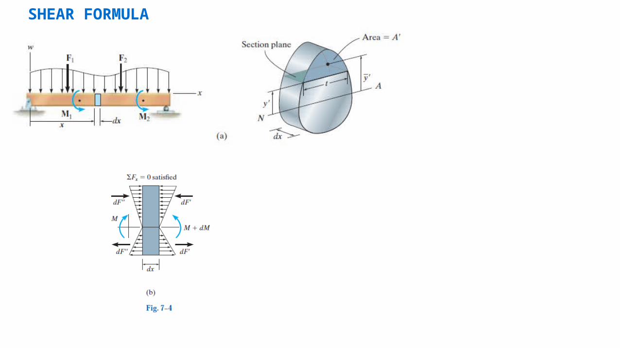
SHEAR FORMULA

ydAdx
dM
It
tdxdAI
MydA
I
ydMM
tdxdAdA
Fx
1
0
0''
0
'' where
'
AyydAQ
It
VQ
A
Q is called the first area moment of the section above y’.t is the average shear stress over the area tdx, and it is also the average shear stress on the cross-section y’ above the neutral axis.

What if you take a vertical cut?
What is dF?
s’
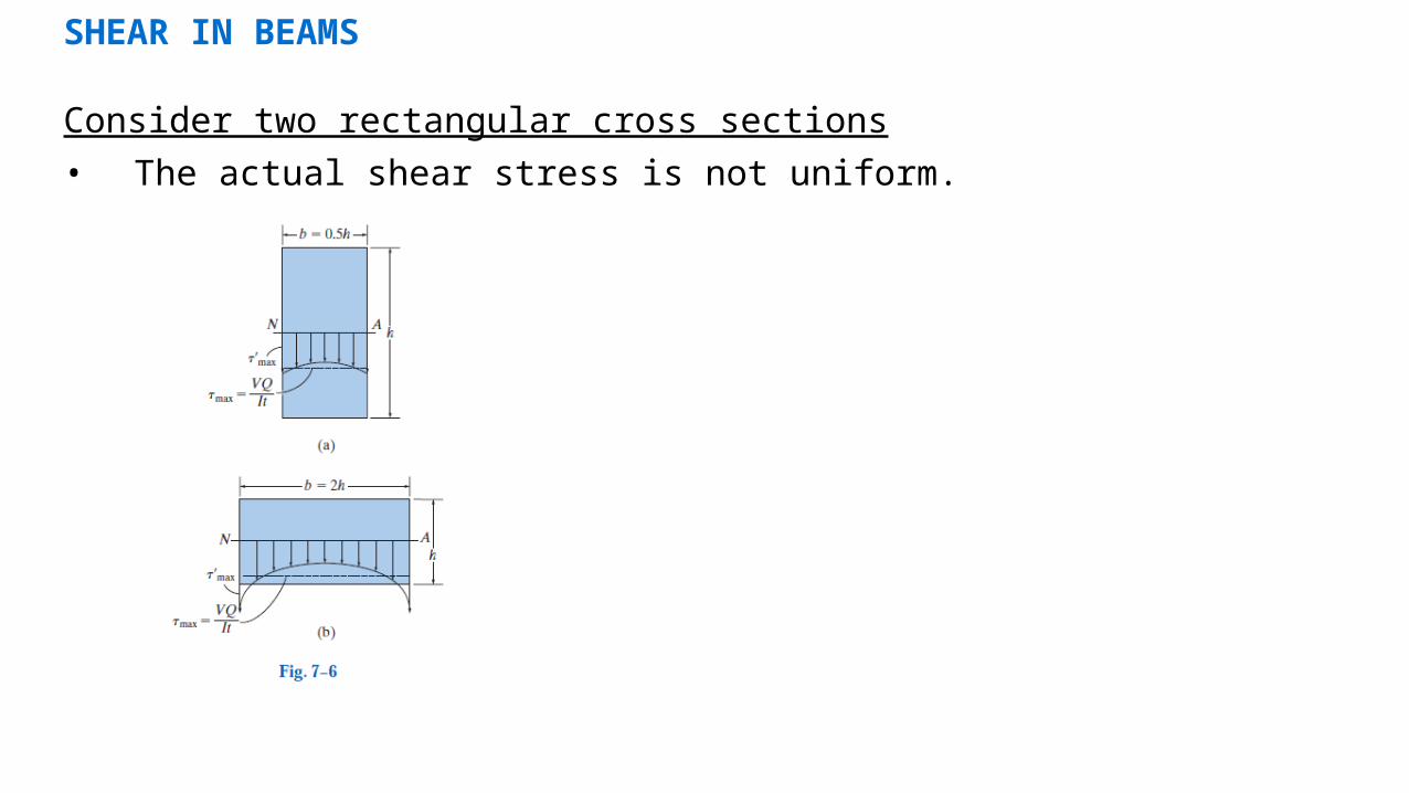
SHEAR IN BEAMS
Consider two rectangular cross sections
• The actual shear stress is not uniform.

Rectangular cross section
A
V
yhb
yh
yh
b
yyh
bQ
Qbbh
V
It
VQ
5.1
22
22
2
')2
(
121
max
22
3
SHEAR IN BEAMS

EXAMPLE 7.3
A steel wide-flange beam has the dimensions shown in Fig. 7–11a. If it is subjected to a shear of V = 80kN, plot the shear-stress distribution acting over the beam’s cross-sectional area.

EXAMPLE 1 (cont)
Copyright © 2011 Pearson Education South Asia Pte Ltd
• The moment of inertia of the cross-sectional area about the neutral axis is
• For point B, tB’ = 0.3m, and A’ is the dark shaded area shown in Fig. 7–11c
Solutions
4623
3
m 106.15511.002.03.002.03.012
12
2.0015.012
1
I
MPa 13.13.0106.155
1066.01080
m 1066.002.03.011.0''
6
33
'
''
33'
B
BB
B
It
VQ
AyQ

EXAMPLE 1 (cont)
• For point B, tB = 0.015m, and QB = QB’,
• For point C, tC = 0.015m, and A’ is the dark shaded area in Fig. 7–11d.
• Considering this area to be composed of two rectangles,
• Thus,
Solutions
MPa 6.22
015.0106.155
1066.010806
33
B
BB It
VQ
33 m 10735.01.0015.005.002.03.011.0'' AyQC
MPa 2.25
015.0106.155
10735.010806
33
max
C
cC It
VQ

7.3 SHEAR FLOW IN BUILT-UP BEAM
• Shear flow ≡ shear force per unit length along longitudinal axis of a beam.
I
VQ
dx
dFq
QI
dMydA
I
dMdF
dAdAdF
'
''' q = shear flow (shear force per unit thickness)V = internal resultant shearI = moment of inertia of the entire cross-sectional area

SHEAR FLOW IN BUILT-UP BEAM (cont)
The horizontal (direction parallel to the neutral axis) cuts can be long.The vertical cuts must be short.

EXAMPLE 7.6
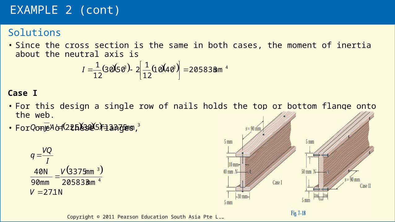
Nails having a total shear strength of 40 N are used in a beam that can be constructed either as in Case I or as in Case II, Fig. 7–18. If the nails are spaced at 90 mm, determine the largest vertical shear that can be supported in each case so that the fasteners will not fail.
EXAMPLE 2 (cont)
Copyright © 2011 Pearson Education South Asia Pte Ltd
• Since the cross section is the same in both cases, the moment of inertia about the neutral axis is
Case I
• For this design a single row of nails holds the top or bottom flange onto the web.
• For one of these flanges,
Solutions
433 mm 205833401012
125030
12
1
I
N 1.27mm 205833
mm 3375
mm 90
N 40
mm 33755305.22''
4
3
3
V
V
I
VQq
AyQ

EXAMPLE 2 (cont)
Case II
• Here a single row of nails holds one of the side boards onto the web.
• Thus,
Solutions
(Ans)N 3.81mm 205833
mm 1125
mm 90
N 40
mm 11255105.22''
4
3
3
V
V
I
VQq
AyQ

SHEAR FLOW IN THIN-WALLED BEAM
• Approximation: only the shear-flow component that acts parallel to the walls of the member will be counted.

EXAMPLE 3
The thin-walled box beam in Fig. 7–22a is subjected to a shear of 10 kN. Determine the variation of the shear flow throughout the cross section.
• The moment of inertia is
• For point B, the area thus q’B = 0.
• Also,
• For point C,
• The shear flow at D is
Solutions
0'A
433 mm 1846412
186
12
1I
3
3
cm 304122'
cm 5.17155.3'
AyQ
AyQ
D
C
N/mm 5.91 kN/cm 951.0
184
2/5.1710
I
VQq C
C
N/mm 163 kN/cm 63.1
184
2/3010
I
VQq D
D