chapter 6 design guidance - rtcsnv.com · chapter 6 design guidance ... transportation officials...
TRANSCRIPT

REGIONAL BICYCLE AND PEDESTRIAN PLAN FOR SOUTHERN NEVADA | 189
CHAPTER 6
Design Guidance
Nevada Moves Day
River Mountains Loop Trail

190 | REGIONAL BICYCLE AND PEDESTRIAN PLAN FOR SOUTHERN NEVADA
Introduction to Design Guidance
The sections that follow serve as an inventory of
bicycle design treatments and provide guidelines
for their development. These treatments and
design guidelines are important because they
represent the tools for creating communities that
are friendly, safe, and accessible for people walk-
ing and bicycling. The guidelines are not, how-
ever, a substitute for a more thorough evaluation
by a landscape architect or engineer upon imple-
mentation of facility improvements.
The following standards and guidelines are
referred to in this guide.
NATIONAL GUIDANCE
American Association of State Highway and
Transportation Officials (AASHTO) Guide for
the Development of Bicycle Facilities (2013),
updated in June 2012 provides guidance on
dimensions, use, and layout of specific bicycle
facilities.
The National Association of City Transportation
Officials’ (NACTO) Urban Bikeway Design
Guide (2012) is the newest publication of
nationally recognized bikeway design stan-
dards, and offers guidance on the current state
of the practice designs.
The AASHTO Policy on Geometric Design
of Highways and Streets (2011) commonly
referred to as the “Green Book,” contains the
current design research and practices for high-
way and street geometric design.
IMPACT ON SAFETY AND CRASHES
The presence of bicycle facilities significantly
can improve roadway user safety. The Federal
Highway Administration’s (FHWA) Crash
Modification Factor Clearinghouse (http://
www.cmfclearinghouse.org/) is a web-based
database of Crash Modification Factors (CMF)
to help transportation engineers identify the
most appropriate countermeasure for their
safety needs. Where available and appropriate,
CMFs or similar study results are included for
each treatment.
Guidance
Figure 6.1:
National Design Guidance Manual Covers

REGIONAL BICYCLE AND PEDESTRIAN PLAN FOR SOUTHERN NEVADA | 191
REGIONAL GUIDANCE
The RTC Policy for Complete Streets (and
corresponding Complete Streets Design
Guidelines for Livable Communities) estab-
lishes the broad framework and goals for
accommodating all modes, including bicyclists
and pedestrians throughout Southern Nevada.
These policies and guidelines were used as a
foundation for this document.
The policy established goals to support trans-
portation choices; livable neighborhoods and
commercial centers located along the region’s
transportation corridors; and multimodal road-
way design that will not compromise the needs
of larger vehicles such as transit vehicles, fire
trucks, and freight delivery trucks. The inclusion
of Complete Streets design elements will allow
for design flexibility on different street func-
tions and neighborhood contexts. Additionally,
complete-streets designs will improve the inte-
gration of land use and transportation, while
encouraging economic revitalization through
infrastructure improvements. The RTC pro-
vides Uniform Standard Drawings as design
guidance for roadway projects.
STATE GUIDANCE
The Nevada Department Of Transportation
(NDOT) Road Design Guide (2010) establishes
uniform design criteria and interpretation of
the AASHTO Green Book’s geometric design
elements.
The NDOT Standard Plans for Road and
Bridge Construction (undergoing update)
include CAD drawings of street design cross
sectional elements and details.
The NDOT Standard Specifications for Road
and Bridge Construction (2014) include import-
ant details for contractor processes and stan-
dards in the design and construction of roads.
The NDOT Landscape and Aesthetics Master
Plan (2002) established policies, procedures,
standards, and guidelines for landscape and
aesthetic treatments on Nevada’s roads and
highways.
Figure 6.2:
State Design Guidance Manual Covers

192 | REGIONAL BICYCLE AND PEDESTRIAN PLAN FOR SOUTHERN NEVADA
AVERAGE ANNUAL DAILY TRAFFIC (1,000 veh/day or 100 veh/peak hr)
BICYCLE BOULEVARD
BIKE ROUTE
BIKE LANE
SHARED USE PATH
BUFFERED BICYCLE LANE
SEPARATED BICYCLE LANE
FACILITY TYPE
POSTED TRAVEL SPEED (mph)
20 30 40 5025 35 45 5515 60+
1062 15+ 25+4 80 20+ 30+STREET CLASS
LOCAL
COLLECTORARTERIAL
COLLECTORARTERIAL
COLLECTORARTERIAL
COLLECTORARTERIAL
LOCAL
SPEED
max
max
min
min
VOLUME
Desired AcceptableAcceptable
Selecting the most appropriate bicycle facility
type for a given roadway can be challenging,
due to the range of factors that influence bicycle
users’ comfort and safety. There is a significant
impact on bicycling comfort when the speed
differential between bicyclists and motor vehi-
cle traffic is high and/or motor vehicle traffic vol-
umes are high.
FACILITY SELECTION
As a starting point to identify a preferred facility,
the chart below provides guidance on selecting
the recommended type of bikeway to be pro-
vided in particular roadway based on speeds
and volumes.
To use this chart, identify the appropriate daily
traffic volume and travel speed on the existing
or proposed roadway, and then locate the facil-
ity types indicated by those key variables.
Other factors beyond speed and volume that
affect facility selection include traffic mix of
automobiles and heavy vehicles, the presence
of on-street parking, intersection density, sur-
rounding land use, and roadway sight distance.
These factors are not included in the facility
selection chart below, but should always be
considered in the facility selection during the
design process. The table in Figure 6.3 serves
as a guide and starting point for facility selection
but is not a substitute for engineering judgment.
Figure 6.3:
Bicycle Facility Selection Guidance Table
Bicycle Facility Selection

REGIONAL BICYCLE AND PEDESTRIAN PLAN FOR SOUTHERN NEVADA | 193
Bicycle User Type
The current AASHTO Guide for the
Development of Bicycle Facilities encourages
designers to identify their typical rider type
based on the trip purpose (recreational vs
transportation) and on the level of comfort and
skill of the typical rider (casual vs. experienced).
A user-type framework for understanding a
potential rider’s willingness to ride a bike is
illustrated in Figure 6.4. Developed by planners
in Portland, OR and supported by research, this
classification identifies four distinct types of
bicyclists.
FOUR TYPES OF TRANSPORTATION
BICYCLISTS
Strong and Fearless (1% of population) –
Characterized by those that will typically ride
anywhere regardless of roadway conditions or
weather. These bicyclists can ride faster than
other user types, prefer direct routes and will
typically choose roadway connections – even
if shared with vehicles – over separate bicycle
facilities such as shared-use paths.
Enthused and Confident (5-10% of population)
– This user group encompasses people who are
fairly comfortable riding on all types of bikeways
but usually choose low traffic streets or shared-
use paths when available. These bicyclists may
deviate from a more direct route in favor of a
preferred facility type. This group includes all
kinds of current commuter, recreational, racer,
and utilitarian bicyclists.
Interested but Concerned (60% of population)
– This type of person comprises the bulk of the
population and represents people who typically
only ride a bicycle on low traffic streets or
shared-use paths under favorable weather con-
ditions, if at all. They perceive significant barriers
to their bicycling more, specifically traffic and
other safety issues. These people may become
“Enthused and Confident” with encouragement,
education, and experience. Improvements to
the network to attract this category of rider has
the largest potential to increase ridership.
No Way, No How (30% of population) – Persons
in this category are not bicyclists, and perceive
severe or insurmountable safety issues with rid-
ing a bicycle. Some people in this group may
eventually become more regular riders with
time and education. A significant portion of
these people will not ride a bicycle under any
circumstances.
1%
5-10%
60%
30%
Interested but Concerned
No Way, No How
Enthused and Confident
Strong and Fearless
Figure 6.4:
Typical Distribution of Bicyclist Types

194 | REGIONAL BICYCLE AND PEDESTRIAN PLAN FOR SOUTHERN NEVADA
The specific type of treatment at a crossing
may range from simple, marked crosswalks to
full traffic signals or grade separated crossings.
Crosswalk lines should not be used indiscrimi-
nately, and appropriate selection and implemen-
tation of crossing treatments should be evalu-
ated by an engineer or an engineering study
before installation. Many of the factors in Figure
6.6 should be considered, including the number
of lanes, the presence or lack of a median, the
distance from adjacent signalized intersections,
the pedestrian volumes and delays, the aver-
age daily traffic (ADT), the posted or statutory
speed limit and the 85th-percentile speed, the
roadway geometry of the location, the possible
consolidation of multiple crossing points, the
availability of street lighting, and other appropri-
ate factors.
MIDBLOCK CROSSINGS
Midblock crossings are an important street
design element for pedestrians. They can pro-
vide a legal crossing at locations where pedes-
trians want to travel, and can be safer than
crossings at intersections because traffic is only
moving in two directions. Locations where mid-
block crossings should be considered include:
• Long blocks (longer than 600 feet) with des-
tinations on both sides of the street.
• Locations with heavy pedestrian traffic,
such as schools, shopping centers.
• Midblock transit stops, where transit riders
must cross the street on one leg of their
journey. The table in Figure 6.6 serves as a
guide and starting point for crossing treat-
ment selection but is not a substitute for
engineering judgment.
Pedestrian Crossing Location and Facility Selection
Figure 6.5:
Pedestrian Crossing at a Roundabout

REGIONAL BICYCLE AND PEDESTRIAN PLAN FOR SOUTHERN NEVADA | 195
Figure 6.6:
Crossing Treatment Selection Guidance
FACILITY TYPE
PEDESTRIAN CROSSINGCONTEXTUAL GUIDANCE
LEGEND
At unsignalized locations
2 lane 3 lane 2 lane
2 lane with median refuge 3 lane 2 lane
2 lane with median refuge 3 lane 4 lane
4 lane with median refuge 5 lane 6 lane
6 lane with median refuge
Crosswalk Only (high visibility)
EJ EJ X EJ EJ X X X X X X
Crosswalk with warning signage and yield lines EJ EJ EJ EJ
EJ EJ
X X X X X
X X X X X
Active Warning Beacon (RRFB)
Stop Sign Controlled
X EJ X X X
X X X
X
Hybrid Beacon X X EJ EJ EJ EJ
PELICAN Signal X X X X X XEJ
Most Desirable Engineering Judgement EJ
Not Preferred X
Local Streets15-25 mph
Collector Streets25-30 mph
Arterial Streets30-45 mph
EJ EJ EJ EJ
Full Tra�c Signal X X EJ EJ EJ EJ EJ EJ
Grade separation X X EJ EJ EJ X EJ EJ
1
2
3
4
5
6
7
8
Figure 6.7:
Examples of Crossing Treatments
1. Marked Crosswalk
4. Active Warning
Beacon (RRFB)
5. Pedestrian Hybrid Beacon 6. Full Traffic Signal /
7. PELICAN
8. Grade Separation
2. Crosswalk with Warning Signage 3. Stop Sign Controlled

196 | REGIONAL BICYCLE AND PEDESTRIAN PLAN FOR SOUTHERN NEVADA
Pedestrian Facilities
Sidewalks are the most fundamental element of
the walking network, as they provide an area for
pedestrian travel separated from vehicular traf-
fic. Providing adequate and accessible facilities
can lead to increased numbers of people walk-
ing, improved safety, and the creation of social
space.
TYPICAL APPLICATION
• Sidewalks should be provided on both sides
of urban commercial streets, and should be
required in areas of moderate residential
density (1-4 dwelling units per acre).
• When retrofitting gaps in the sidewalk net-
work, locations near transit stops, schools,
parks, public buildings, and other areas with
high concentrations of pedestrians should
be the highest priority.
Sidewalk Zones and Widths
DESIGN FEATURES
• It is important to provide adequate width
along a sidewalk corridor. A pedestrian
through zone width of six feet enables two
pedestrians (including wheelchair users) to
travel side-by-side, or to pass each other
comfortably.
• In areas of high demand, sidewalks should
contain adequate width to accommodate
high volumes and different walking speeds
of pedestrians. For example, a minimum
8’ wide sidewalk, 10’ preferred, is recom-
mended adjacent to schools.
Figure 6.8:
Sidewalk Near School In Boulder City

REGIONAL BICYCLE AND PEDESTRIAN PLAN FOR SOUTHERN NEVADA | 197
Property Line
Frontage ZonePedestrian Through ZoneFurnishing ZoneParking Lane/Enhancement Zone
Ed
ge
Zo
ne
The Frontage Zone allows pedestrians a comfortable “shy” distance from the building fronts. It provides opportunities for window shopping, to place signs, planters, or chairs.
Not applicable if adjacent to a landscaped space.
The furnishing zone buffers pedestrians from the adjacent roadway, and is also the area where elements such as street trees, signal poles, signs, and other street furniture are properly located.
The through zone is the area intended for pedestrian travel. This zone should be entirely free of permanent and temporary objects.
Wide through zones are needed in downtown areas or where pedestrian flows are otherwise high.
Figure 6.9:
Sidewalk Zones and Widths
Street Classification
Parking Lane/Enhancement
Zone
Furnishing Zone
Pedestrian Through Zone
Frontage Zone
Total
Local Streets Varies 2 - 5 feet 5 - 6 feet N/A 7 - 11 feet
Commercial Areas Varies 4 - 6 feet 6 - 12 feet 2.5 - 10 feet 12.5 - 28 feet
Arterials and Collectors Varies 4 - 6 feet 6 - 8 feet 2.5 - 5 feet 12.5 - 19 feet

198 | REGIONAL BICYCLE AND PEDESTRIAN PLAN FOR SOUTHERN NEVADA
Curb ramps are the design elements that allow
all users to make the transition from the street to
the sidewalk and vice-versa. There are a num-
ber of factors to be considered in the design and
placement of curb ramps at corners. Properly
designed curb ramps ensure that the sidewalk
is accessible from the roadway. A sidewalk with-
out a curb ramp can be useless to someone in a
wheelchair or other mobility disabilities, forcing
them out into the street and back to a driveway
for access.
TYPICAL APPLICATION
• Curb ramps are used to assist people with
mobility devices or disabilities to cross the
street at intersections. They also accom-
modate individuals with bicycles, carts, and
strollers.
Figure 6.10:
Curb Ramp Variants
Parallel Curb RampDiagonal Curb Ramp(not preferred)Perpendicular Curb Ramp
Crosswalk spacing not to scale. For illustration purposes only.
Diagonal ramps shall include a clear space of at least 4 feet within the crosswalk for user maneuverability
Curb ramps shall be located so that they do not project into vehicular traffic lanes, parking spaces, or parking access aisles. Three configurations are illustrated here.
Accessible Curb Ramps
• ADA requires all new and rebuilt curb ramps
to provide accessibility for people with dis-
abilities, including blind pedestrians.
DESIGN FEATURES
• The landing at the top of a ramp shall be
at least 4 feet long and at least the same
width as the ramp itself.
• The ramp shall slope no more than 1:12,
with a maximum cross slope of 2.0%.
• If the ramp runs directly into a crosswalk,
the landing at the bottom will be in the
roadway.
• If the ramp lands on a dropped landing
within the sidewalk or corner area where
someone in a wheelchair may have to
change direction, the landing must be a
minimum of 5 feet long and at least as
wide as the ramp, although a width of 5
feet is preferred.

REGIONAL BICYCLE AND PEDESTRIAN PLAN FOR SOUTHERN NEVADA | 199
Curb extensions minimize pedestrian exposure
during crossing by shortening crossing distance
and giving pedestrians a better chance to see
and be seen before committing to crossing.
TYPICAL APPLICATION
• Within parking lanes appropriate for any
crosswalk where it is desirable to shorten the
crossing distance and there is a parking lane
adjacent to the curb.
• May be possible within non-travel areas on
roadways with excess space.
• Particularly helpful at midblock crossing
locations.
Curb extension length can be adjusted to accommodate bus stops or street furniture.
1 foot buffer from edge of parking lane preferred
Running curb
Extended curb
Crossing distance is shortened
Figure 6.11:
Typical Features of Curb Extensions
Curb Extensions
DESIGN FEATURES
• For purposes of efficient street sweep-
ing, the minimum radius for the reverse
curves of the transition is 10 feet and
the two radii should be balanced to be
nearly equal.
• When a bike lane is present, the curb
extensions should terminate one foot
short of the parking lane to maximize
bicyclist safety.
• Planted curb extensions may be
designed as a bioswale for stormwater
management.

200 | REGIONAL BICYCLE AND PEDESTRIAN PLAN FOR SOUTHERN NEVADA
Green infrastructure treats and slows runoff
from impervious surface areas, such as road-
ways, sidewalks, and buildings. Sustainable
stormwater strategies may include bioretention
swales, rain gardens, tree box filters, and pervi-
ous pavements (pervious concrete, asphalt and
pavers). Bioswales are natural landscape ele-
ments that manage water runoff from a paved
surface, reducing the risks of erosion or flooding
of local streams and creeks, which can threaten
natural habitats. Plants in the swale trap pollut-
ants and silt from entering a water system and
provide an attractive streetscape enhancement.
TYPICAL APPLICATION
• Install in areas without conventional storm-
water systems that are prone to flooding to
improve drainage and reduce costs com-
pared to installing traditional gutter and
drainage systems.
• Use green infrastructure to provide an eco-
logical and aesthetic enhancement of tra-
ditional traffic speed and volume control
measures, such as along a bicycle boulevard
corridor.
• Bioswales and rain gardens are appropriate
at curb extensions and along planting strips.
Figure 6.12:
Streetscape with Green Infrastructure
• Street trees and plantings can be placed in
medians, chicanes, and other locations.
• Pervious pavers can be used along side-
walks, street furniture zones, parking lanes,
gutter strips, or entire roadways where land-
scaping is less desired or feasible.
Green Infrastructure
DESIGN FEATURES
• Bioswales are shallow depressions with
vegetation designed to capture, treat,
and infiltrate stormwater runoff by reduc-
ing velocity and purifying the water while
recharging the underlying groundwater
table.
• Pervious pavement can also effectively
capture and treat stormwater runoff. The
desired storage volume and intended
drain time is determined by the depth of
the pervious layer, void space, and the
infiltration rate of underlying soils. An
underdrain system must be used to treat
overflow, or drain excess runoff to the
municipal sewer system, and allow the
facility to drain within 48 hours.

REGIONAL BICYCLE AND PEDESTRIAN PLAN FOR SOUTHERN NEVADA | 201
• Right-in/right-out restrictions reduce points
of conflict between modes.
• Traffic signals may be considered where
turning movements are very high.
Driveways provide automobile access to private
property but can also cause conflicts with pedes-
trians using the sidewalk at that location. There
are generally two types of driveway designs: inter-
section-type and commercial-type. Commercial-
type driveways maintain the sidewalk across the
intersection which compels motorists to slow
down before crossing. Intersection-type drive-
ways do not maintain the sidewalk through the
intersection and can compromise pedestrian
safety and comfort due to the ability for motorists
to negotiate turns at higher speeds and the lack
of defined right-of-way.
TYPICAL APPLICATION
• Appropriate for all private accessways that
cross sidewalks.
• Ideal for commercial business districts with
high pedestrian activity and slower travel lanes.
Figure 6.13:
Example of Commercial-type Driveway
Driveways
COMMERCIAL-TYPE DESIGN FEATURES
• Sidewalk maintains grade and material
across the driveway to reinforce pedes-
trian right-of-way. Cross slope (driveway
grade) should be no greater than 2.0%.
• Increase curb radius to reduce vehicle
speeds and pedestrian crossing dis-
tance (10-25 feet recommended based
on site activity and street context).
• Minimize driveway widths to reduce
crossing distance and accommodate
entering and exiting vehicles.
• Where turning volumes are high, right-
turn channelization removes slower
turning vehicles from main flow of traffic,
improving motorist yield compliance.

202 | REGIONAL BICYCLE AND PEDESTRIAN PLAN FOR SOUTHERN NEVADA
Pedestrian Facilities at Intersections
A marked crosswalk signals to motorists that
they must stop for pedestrians and encourages
pedestrians to cross at designated locations.
Installing crosswalks alone will not necessarily
make crossings safer, especially on multi-lane
roadways. At mid-block locations, crosswalks can
be marked where there is a demand for crossing
and there are no nearby marked crosswalks.
TYPICAL APPLICATION
All crosswalks should be marked at signalized inter-
sections. At unsignalized intersections, crosswalks
may be marked under the following conditions:
• At a complex intersection, to orient pedestri-
ans in finding their way across.
• At an offset intersection, to show pedestrians
the shortest route across traffic with the least
exposure to vehicular traffic and traffic conflicts.
• At an intersection with visibility constraints,
to position pedestrians where they can best
be seen by oncoming traffic.
• At an intersection within a school zone on a
walking route.
Figure 6.14:
Variants of Marked Crosswalk
Marked Crosswalks
FIGURE X:
Streetscape with Green Infrastructure
The crosswalk should be located to align
as closely as possible with the through
pedestrian zone of the sidewalk corridor
Parallel markings are the most
basic crosswalk marking type
Continental markings
provide additional visibility
DESIGN FEATURES
• The landing at the top of a ramp shall be
at least 4 feet long and at least the same
width as the ramp itself.
• The ramp shall slope no more than 8.33%
with a maximum cross slope of 2.0%.
• If the ramp runs directly into a crosswalk,
the landing at the bottom will be in the
roadway.
• If the ramp lands on a dropped landing
within the sidewalk or corner area where
someone in a wheelchair may have to
change direction, the landing must be a
minimum of 5 feet long and at least as
wide as the ramp itself.

REGIONAL BICYCLE AND PEDESTRIAN PLAN FOR SOUTHERN NEVADA | 203
Median refuge islands are located at the mid-
point of a marked crossing and help improve
pedestrian safety by allowing pedestrians to
cross one direction of traffic at a time. Refuge
islands minimize pedestrian exposure by short-
ening crossing distance and increasing the
number of available gaps for crossing.
TYPICAL APPLICATION
• Can be applied on any roadway with a left
turn center lane or median that is at least 6
feet wide.
• May be appropriate on multi-lane road-
ways depending on speeds and volumes.
Consider configuration with active warning
beacons for improved yielding compliance.
• Appropriate at signalized or unsignalized
crosswalks.
Figure 6.15:
Example of Median Refuge Island
Median Refuge Islands
W11-2,
W16-7P
Cut-through median refuge
islands are preferred over curb
ramps to better accommodate
wheel chairs users.
DESIGN FEATURES
• The island must be accessible, prefera-
bly with at-grade passage through the
island rather than ramps and landings.
Detectable warning surfaces must be
full-width and 3 feet deep to warn blind
pedestrians (DIB 82-05, 2013).
• Requires 6 feet width between travel
lanes (8-10 feet preferred to accommo-
date bikes with trailers and wheelchair
users) and 20 feet length (40 feet pre-
ferred). Clear width of 4 feet required, but
preferably same width as crosswalk.
• On streets with speeds higher than 25
mph, there should also be double cen-
terline marking, reflectors, and “KEEP
RIGHT” signage.

204 | REGIONAL BICYCLE AND PEDESTRIAN PLAN FOR SOUTHERN NEVADA
Active warning beacons are user-actuated illumi-
nated devices designed to increase motor vehicle
yielding compliance at crossings of multi lane or
high volume roadways.
Types of active warning beacons include conven-
tional circular yellow flashing beacons, in-roadway
warning lights, or Rectangular Rapid Flash Beacons
(RRFB). Rectangular rapid flash beacons elicit the
highest increase in compliance of all the warning
beacon enhancement options.
TYPICAL APPLICATION
• Suitable for collector and arterial streets
where speeds are 25-45 mph and there are
two to three total lanes (or four lanes with a
median refuge).
• Implemented at high-volume pedestrian
crossings where a signal is not warranted or
desired, including midblock locations.
• Typically activated by pedestrians manually
with a push button, or can be actuated auto-
matically with passive detection systems.
Figure 6.16:
Example of Active Warning Beacon
Active Warning Beacons
Providing secondary installations of RRFBs on median islands improves conspicuity and driver yielding behavior.
W11-2, W16-7P
Rectangular Rapid Flash Beacons
(RRFB) dramatically increase
compliance over conventional
warning beacons.
DESIGN FEATURES
• Warning beacons shall not be used at
crosswalks controlled by YIELD signs,
STOP signs or traffic signals.
• Warning beacons shall initiate operation
based on pedestrian or bicyclist actua-
tion and shall cease operation at a pre-
determined time after actuation, or with
passive detection after the pedestrian or
bicyclist clears the crosswalk.
• Median refuge islands provide added
comfort and can be angled to direct
users to face oncoming traffic.

REGIONAL BICYCLE AND PEDESTRIAN PLAN FOR SOUTHERN NEVADA | 205
A hybrid beacon, formerly known as a High-intensity
Activated CrosswalK (HAWK), consists of a sig-
nal-head with two red lenses over a single yellow
lens on the major street, and pedestrian and/or bicy-
cle signal heads for the minor street. There are no
signal indications for motor vehicles on the minor
street approaches. Hybrid beacons are used to
improve non-motorized crossings of major streets in
locations where side-street volumes do not support
installation of a conventional traffic signal or where
there are concerns that a conventional signal will
encourage additional motor vehicle traffic on the
minor street. Hybrid beacons may also be used at
mid-block crossing locations.
Figure 6.17:
Example of Pedestrian Hybrid Beacon
Pedestrian Hybrid Beacons
W11-2Push button activation
Pedestrian Hybrid Beacon
Should be installed at least 100 feet from side streets or driveways that are controlled by STOP or YIELD signs.
TYPICAL APPLICATION
• Suitable for arterial streets where speeds are
30-45 mph and there are three or more lanes
of traffic in each direction (or two lanes with a
median refuge).
• Where off-street bicycle facilities intersect
major streets without signalized intersections.
• At intersections or midblock crossings where
there are high pedestrian volumes.
DESIGN FEATURES
• Hybrid beacons may be installed without
meeting traffic signal control warrants if
roadway speed and volumes are exces-
sive for comfortable pedestrian crossings.
• If installed within a signal system, signal
engineers should evaluate the need for
the hybrid signal to be coordinated with
other signals.
• Parking and other sight obstructions
should be prohibited for at least 100 feet
in advance of and at least 20 feet beyond
the marked crosswalk to provide ade-
quate sight distance.

206 | REGIONAL BICYCLE AND PEDESTRIAN PLAN FOR SOUTHERN NEVADA
“Pelican” Crossing
The “Pelican”, or Pedestrian LIght Control
ActivatioN, system is similar to a Pedestrian Hybrid
Beacon but is specifically designed to provide a
two-stage crossing for pedestrians and bicyclists.
The “Pelican” crossing requires the use of a median
island to provide non-motorized users a refuge
between the two crossing stages.
Typically located at mid-block on roadways with
two or more lanes in each direction, the “Pelican”
crossing reduces the number and length of poten-
tial stops and stop time (delay) by separating any
pedestrian crossing into two phases. The user desir-
ing to cross activates the first of two signals by push
button. Once there is a red indication for roadway
traffic, a “Walk” symbol indicates to the pedestrian
or bicyclist that the first phase has begun. The user
walks to and along the median to activate the sec-
ond signal by pressing its push button. The second
Figure 6.18:
Example of Pelican Crossings
A curb ramp should be
the full width of the path
Crosswalk markings
legally establish midblock
crossing
Detectable warning strips
help visually impaired
pedestrians identify the
edge of the street
Push button
Activation
May be paired with a
bicycle signal head to
clarify bicycle movement
Median required
phase begins shortly thereafter with the same indi-
cations and timing as the first. The “Pelican” uses a
standard red-yellow-green signal for motorists and,
like the Pedestrian Hybrid Beacon, remains green
(or blank in the case of the latter) unless activated
by a user desiring to cross. Bicyclists should yield
to pedestrians in the crossing and the median, dis-
mounting if necessary.
DESIGN FEATURES
• May be installed without meeting traffic
signal control warrants if roadway speed
and volumes are excessive for comfort-
able pedestrian crossings.
• Required a median to produce a two-
stage crossing.
• Parking and other sight obstructions
should be prohibited for at least 100 feet
in advance of and at least 20 feet beyond
the marked crosswalk to provide ade-
quate sight distance.

REGIONAL BICYCLE AND PEDESTRIAN PLAN FOR SOUTHERN NEVADA | 207
Scramble Crosswalk
A scramble crosswalk, also known as exclusive
pedestrian phase (EPP) or Barnes Dance, is a signal
phasing type in which pedestrians are permitted
exclusive use of the intersections in all directions,
potentially including diagonal crossings.
TYPICAL APPLICATION
There are no formally established warrants for a
full exclusive pedestrian scramble. Traffic engi-
neers should balance the demand for green
time between pedestrian volume and vehicle
volume. While an exclusive pedestrian phase
will traditionally increase delay for motor vehicles
(by eliminating vehicle green time for a phase) at
high pedestrian volumes an exclusive phase may
actually reduce vehicle delay by providing unob-
structed access through the intersection.
Figure 6.19:
Example of Scramble Crosswalk
Detectable warning strips help visually impaired pedestrians identify the edge of the street
Push button activation
Markings should indicate opportunity for diagonal crossing
The AASHTO Pedestrian Guide 2004 indicates
that exclusive/scramble phases work best when:
• Pedestrian volume exceeds 1200 pedestri-
ans per day
• Street widths are narrow (less than 60 ft), and
• Trough movement volume is low
DESIGN FEATURES
• Crosswalk markings should clearly indicate
the opportunity and intent to support diago-
nal crossings.
• At diagonal crossings, the walking time
should be calculated to serve the longer
diagonal travel distances. The MUTCD rec-
ommends a walking speed of 3.5 ft/s.
• Where an exclusive pedestrian phase is not
feasible, a 3 second Leading Pedestrian
Interval may provide some of the benefits
while minimizing impacts to motor vehicles.
Travel time should be calculated based on longer diagonal travel distance

208 | REGIONAL BICYCLE AND PEDESTRIAN PLAN FOR SOUTHERN NEVADA
Bicycle Facilities
Bicycle Parking
Bicyclists expect a safe, convenient place to secure
their bicycle when they reach their destination. This
may be short-term parking of 2 hours or less, or
long-term parking for employees, students, resi-
dents, and commuters.
TYPICAL APPLICATION
• Short-term parking should consist of
approved standard racks, with appropriate
location and placement to serve nearby uses.
• Bike corrals consist of bicycle racks grouped
together in a common area. These can be
implemented by converting motor vehicle
parking spaces into on-street bicycle park-
ing, or as part of a curb extension for off-
street bicycle parking. Each motor vehicle
parking space can be replaced with approxi-
mately 6-10 bicycle parking spaces.
Figure 6.20:
Examples of Bicycle Parking
BIKE RACKS
BIKE LOCKER
BIKE CORRAL
• Bicycle lockers are intended to provide long-
term bicycle storage while protecting entire
bicycle against theft and inclement weather.
Lockers should be placed in visible, eas-
ily accessible locations while maintaining
security.
DESIGN FEATURES
Bike Racks
• 2 ft min. from the curb face to avoid ‘dooring.’ 4 ft between racks to provide maneuvering room. 50 ft max. distance from main building entrance. Min. clear distance of 6 ft property line.
Bike Corrals
• 5-6 ft entrance width from the roadway. Can be used with parallel or angled parking.
Bike Lockers
• Min. dimensions: 2.5 ft W; 4 ft H; 6 ft D. Four ft side clearance and 6 ft end clearance. Seven
ft min. distance between facing lockers.

REGIONAL BICYCLE AND PEDESTRIAN PLAN FOR SOUTHERN NEVADA | 209
Shared roadways (or bike routes) are roadways with-
out dedicated bicycle facilities that include Shared
Lane Marking stencils and wayfinding signage as
additional treatments. The stencils can serve a num-
ber of purposes, such as making motorists aware of
the need to share the road with bicyclists, showing
bicyclists the proper direction of travel, and, with cor-
rect placement, reminding bicyclists to bike farther
from parked cars to prevent “dooring” collisions.
TYPICAL APPLICATION
• Shared lane markings are not appropriate on
paved shoulders or in bike lanes, and should
not be used on roadways that have a speed
limit above 30 mph.
• Shared Lane Markings pair well with MUTCD
R4-11 “Bikes May Use Full Lane” signs.
Shared Roadway
Figure 6.21:
Example of Shared Roadway
Placement in center of travel lane is preferred in constrained conditions
When placed adjacent to parking, sharrows should be outside of the “Door Zone”. Minimum placement is 11 feet from curb
MUTCD R4-11 (optional)
MUTCD D11-1 (optional)
DESIGN FEATURES
• When placed adjacent to parking, shar-
rows should be outside of the “door
zone”. Minimum placement is 11 feet from
curb.
• Placement in center of the travel lane is
preferred in constrained conditions.
• Markings should be placed immediately
after intersections and spaced at 250 feet
intervals thereafter.
• Consider modifications to signal timing to
induce a bicycle-friendly travel speed for
all users.

210 | REGIONAL BICYCLE AND PEDESTRIAN PLAN FOR SOUTHERN NEVADA
Bicycle boulevards are low-volume, low-speed
streets modified to enhance bicyclist comfort
by using treatments such as signage, pavement
markings, traffic calming and/or traffic reduc-
tion, and intersection modifications. These
treatments allow through movements of bicy-
clists while discouraging similar through-trips by
non-local motorized traffic.
TYPICAL APPLICATION
• Parallel with and in close proximity to major
thoroughfares (1/4 mile or less).
• Follow a desire line for bicycle travel that is
ideally long and relatively continuous (2-5
miles).
• Avoid alignments with excessive zigzag or
circuitous routing. The bikeway should have
less than 10% out of direction travel com-
pared to shortest path of primary corridor.
Figure 6.22:
Example of Bicycle Boulevard
Bicycle Boulevards
Signs and pavement markings identify the street as a bicycle priority route and provide positioning guidance.
Wayfinding signage provides directions, distance and estimated travel time to nearby destinations.
Main St
Industrial Dist
Waterfront
0.1 MI. 1 MIN.
2.0 MI. 15 MIN.
3.0 MI. 20 MIN.
• Streets with travel speeds at 25 mph or less
and with traffic volumes of fewer than 3,000
vehicles per day. These conditions should
either exist or be established with traffic calm-
ing measures.
DESIGN FEATURES
• Signs and pavement markings are the
minimum treatments necessary to desig-
nate a street as a bicycle boulevard.
• Maximum posted speed of 25 mph. Utilize
reduced speed limits or horizontal or ver-
tical deflection strategies to maintain an
85th percentile speed less than 22 mph.
• Implement volume control treatments
based on the context of the bicycle bou-
levard, using engineering judgment.
Target motor vehicle volumes should be
3,000 vehicles per day or below.
• Intersection crossings should be
designed to enhance safety and minimize
delay for bicyclists (see pages 42-43).
Chicanes slow vehicle trafficfor a comfortable cyclingenvironment

REGIONAL BICYCLE AND PEDESTRIAN PLAN FOR SOUTHERN NEVADA | 211
On-street bike lanes designate an exclusive
space for bicyclists through the use of pave-
ment markings and signage. The bike lane is
located directly adjacent to motor vehicle travel
lanes and is used in the same direction as motor
vehicle traffic. Bike lanes are typically on the
right side of the street, between the adjacent
travel lane and curb, road edge, or parking lane.
TYPICAL APPLICATION
• Bike lanes may be used on any street with
adequate space, but are most effective
on streets with moderate traffic volumes
(between 4,000 and 15,000 ADT).
• Bike lanes are most appropriate on streets
with moderate speeds of approx. 20-30 mph.
• Appropriate for skilled adult riders on most
streets.
• May be appropriate for children when config-
ured as 6+ foot wide lanes on lower-speed,
lower-volume streets with one lane in each
direction.
Figure 6.23:
Example of On-Street Bicycle Lane
On-Street Bicycle Lanes
Bicycle lane marking
5-6 foot preferred curb-adjacent lane width
6 inch striped line
6 foot preferred parking-adjacent lane width
DESIGN FEATURES
• Mark the inside line with a 6 inch stripe.
Indicate a parking lane with a 4 inch line
or mark individual parking spaces with
4 inch wide lines in a 12 inch by 12 inch
crosshair or 12 inch by 6 inch “T” marker.
• Include a bicycle lane marking (at the
beginning of blocks and at regular inter-
vals along the route.
• 6 foot width preferred adjacent to
on-street parking, (5 foot min.)
• 5–6 foot preferred adjacent to curb and
gutter (4 foot min.) or 4 feet more than the
gutter pan width.

212 | REGIONAL BICYCLE AND PEDESTRIAN PLAN FOR SOUTHERN NEVADA
Buffered bike lanes are conventional bicycle
lanes paired with a designated, painted buf-
fer space, separating the bicycle lane from the
adjacent motor vehicle travel lane and/or park-
ing lane.
TYPICAL APPLICATION
• Anywhere a conventional bike lane is being
considered.
• On streets with relatively higher speeds (25
to 40 mph) and automobile or truck volumes
(4,000 to 25,000 AADT).
• On streets with extra lanes or lane width.
• Appropriate for skilled adult riders on most
streets.
• In areas with high parking turnover, such as in
front of schools, the bike lane may be placed
adjacent to the curb with a buffer between
the bike lane and the parking lane.
Figure 6.24:
Example of Buffered Bike Lane
Buffered Bicycle Lanes
5 foot minimum bicycle travel area
2 foot minimum buffer width
DESIGN FEATURES
• The minimum bicycle travel area (not
including buffer) is 5 feet wide.
• Buffers should be at least 18 inches wide.
If buffer area is 3 feet or wider, white
chevron or diagonal markings should be
used.
• Consider a dotted line for clarity at drive-
ways or minor street crossings.
• There is no standard for whether the buf-
fer is configured on the parking side, the
travel side, or a combination of both.

REGIONAL BICYCLE AND PEDESTRIAN PLAN FOR SOUTHERN NEVADA | 213
One-way separated bicycle lanes are on-street
bikeway facilities that are separated from vehicle
traffic. Protection for separated bicycle lanes is pro-
vided through physical barriers between the bike
lane and the vehicular travel lane. These barriers
can include bollards, concrete or plastic mounds,
flexible posts, planters, medians, extruded curbs,
jersey barriers, bike racks, on-street parking, or
a combination of these. If possible, the barrier
should allow standard street sweeping equipment
to maintain the bike lane while still providing sep-
aration for people on bicycles. Separated bike
lanes using these barrier elements typically share
the same elevation as adjacent travel lanes, but
the bike lane could also be raised above street
level, either below or equivalent to sidewalk level.
TYPICAL APPLICATION
• Along streets on which conventional bicycle
lanes would cause many bicyclists to feel stress
because of factors such as multiple lanes, high
bicycle volumes, high motor traffic volumes
(preferably 9,000-30,000 ADT), higher traffic
speeds (30+ mph), high incidence of double
parking, higher truck traffic (10% of total ADT),
and high parking turnover.
• Along streets for which conflicts at intersec-
tions can be effectively mitigated using parking
lane setbacks, bicycle markings through the
intersection, and other signalized intersection
treatments.
Figure 6.25:
Example of One-Way Separated Bike Lane
One-Way Separated Bike Lanes
7 foot preferred width
3 foot minimum buffer width
DESIGN FEATURES
• Pavement markings, symbols and/or arrow
markings must be placed at the beginning
of the separated bike lane and at intervals
along the facility based on engineering
judgment.
• 7 foot width preferred in areas with high
bicycle volumes or uphill sections to
facilitate safe passing behavior (5 foot
minimum).
• 3 foot minimum buffer width adjacent to
parking lines (18 inch minimum adjacent
to travel lanes), marked with 2 solid white
lines.

214 | REGIONAL BICYCLE AND PEDESTRIAN PLAN FOR SOUTHERN NEVADA
Two-way Separated Bike Lanes are bicycle facil-
ities that allow bicycle movement in both direc-
tions on one side of the road. Two-way sepa-
rated bike lanes share some of the same design
characteristics as one-way separated bicycle
lanes, but may require additional considerations
at driveway and side-street crossings.
Figure 6.26:
Example of Two-Way Separated Bike Lane
Two-Way Separated Bike Lanes
3 foot minimum buffer or island width when adjacent to on-street parking
12 foot preferred operating width
TYPICAL APPLICATION
• Works best on the left side of one-way streets.
• Streets with high motor vehicle volumes and/
or speeds (similar to one-way).
• Streets with high bicycle volumes.
• Streets with a high incidence of wrong-way
bicycle riding.
• Streets with few conflicts, such as driveways
or cross-streets, on one side of the street.
• Streets that connect to shared use paths.
DESIGN FEATURES
• 12 foot operating width preferred (10 feet
minimum) width for two-way facility. In
constrained areas, an 8 foot minimum
operating width may be considered.
• Adjacent to on-street parking a 3 foot
minimum width channelized buffer or
island shall be provided to accommodate
opening doors.
• Separation narrower than 5 feet may be
permitted if physical barrier separation is
present.

REGIONAL BICYCLE AND PEDESTRIAN PLAN FOR SOUTHERN NEVADA | 215
Shared Use Paths
A shared use path can provide a desirable facil-
ity, particularly for recreational users and people
of all skill levels preferring separation from traf-
fic. Paths should generally provide directional
travel opportunities not provided by existing
roadways.
TYPICAL APPLICATION
• Commonly established in natural greenway
corridors, utility corridors, or along aban-
doned and converted rail corridors.
• May be established as short accessways
through neighborhoods or to connect to
cul-de-sacs.
• May be established along roadways as an
alternative to on-street bicycle riding. This
configuration is called a sidepath and is dis-
cussed further on the next page.
Figure 6.27:
Example of Shared Use Path
12 foot preferred width (10 foot acceptable)
Typical Shared Use Paths
DESIGN FEATURES
• Recommended 10 feet width to accom-
modate moderate usage (12 feet pre-
ferred for heavy use). Minimum 8 feet
width for low traffic situations only or in
constrained areas.
• Minimum 2 feet shoulder width on both
sides of the path, with an additional foot
of lateral clearance as required by the
MUTCD for the installation of signage or
other furnishings.
• Recommended 10 feet clearance to
overhead obstructions (8 feet minimum).
• When striping is required, use a 4 inch
dashed yellow centerline stripe with 4
inch solid white edge lines. Solid center-
lines can be provided on tight or blind
corners, and on the approaches to road-
way crossings.

216 | REGIONAL BICYCLE AND PEDESTRIAN PLAN FOR SOUTHERN NEVADA
• Work best on roadways with fewer than 12
driveways or 6 intersections per mile.
Shared use paths can be located along road-
ways (also called sidepaths). These facilities are
bidirectional shared use paths located immedi-
ately adjacent and parallel to a roadway, when
an independent right of way is not available.
Sidepaths can offer a high-quality experience
for users of all ages and abilities.
TYPICAL APPLICATION
• For completing networks where existing
roads are the only corridors available.
• To connect sections of independent paths or
low-stress local routes such as shared use
paths and bicycle boulevards.
• Adjacent to freeways where bicyclists are
prohibited from using the roadway facility.
• Work best on roadways with high operating
speeds and/or high motor vehicle volumes.
Figure 6.28:
Example of Shared Use Paths Along Roadway
Shared Use Paths Along Roadways
Pathway RoadwayRoadway Separation
10 foot preferred minimum width
6.5 foot preferred minimum buffer
DESIGN FEATURES
• Preferred minimum pathway width for
two-way shared use is 10 feet. In low
volume or constrained situations, 8 feet
minimum may be adequate. A minimum
2 -foot clear space should be provided
on both sides of the path.
• Preferred minimum roadway separa-
tion width is 6.5 feet, with an absolute
minimum separation width of 5 feet per
AASHTO guidelines. Minimum dimen-
sion separation is only appropriate on
lower speed roadways. (≤ 45 mph).
• Separation narrower than 5 feet is not
recommended (AASHTO min.), although
may be accommodated with the use of
a physical barrier between the sidepath
and the roadway.

REGIONAL BICYCLE AND PEDESTRIAN PLAN FOR SOUTHERN NEVADA | 217
At-grade roadway crossings can create poten-
tial conflicts between path users and motorists.
However, well-designed crossings can mitigate
many operational issues and provide a higher
degree of safety and comfort for path users.
The approach to designing path crossings of
streets depends on an evaluation of vehicular
traffic, line of sight, pathway traffic, use pat-
terns, vehicle speed, road type, road width, and
other safety issues such as proximity to major
attractions.
TYPICAL APPLICATION
• Unsignalized marked crossings are appro-
priate on two lane roads with ≤9,000-12,000
Average Daily Traffic (ADT) volumes, and
speeds below 35 mph. Crossings of streets
with higher speeds, higher volumes, and
additional lanes require additional enhance-
ments such as median islands, active warn-
ing beacons, or signals.
• In most cases, path crossings should not be
provided within approximately 400 feet of an
existing signalized intersection. If possible,
route the path directly to the signal. Barriers,
signing, and sidepaths may be needed to
direct shared use path users to the signal-
ized crossings
• At signal-controlled crossings, full traffic sig-
nal installations must meet MUTCD pedes-
trian, school, or modified warrants. Signalized
crossings should be located more than 400
feet from an existing signalized intersection,
and include push button actuation for shared
use path users. The maximum delay for acti-
vation of the signal should be two minutes.
Figure 6.29:
Examples of Shared Use Path Crossings
Shared Use Path Crossings
Route Users to Signal Signal ControlMarked Uncontrolled Crossing
218 | REGIONAL BICYCLE AND PEDESTRIAN PLAN FOR SOUTHERN NEVADA
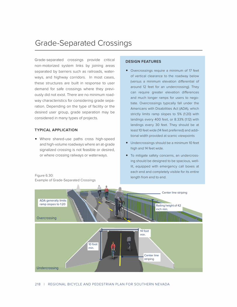
Grade-separated crossings provide critical
non-motorized system links by joining areas
separated by barriers such as railroads, water-
ways, and highway corridors. In most cases,
these structures are built in response to user
demand for safe crossings where they previ-
ously did not exist. There are no minimum road-
way characteristics for considering grade sepa-
ration. Depending on the type of facility or the
desired user group, grade separation may be
considered in many types of projects.
TYPICAL APPLICATION
• Where shared-use paths cross high-speed
and high-volume roadways where an at-grade
signalized crossing is not feasible or desired,
or where crossing railways or waterways.
Grade-Separated Crossings
Center line striping
Overcrossing
Undercrossing
Railing height of 42 inch min.
Figure 6.30:
Example of Grade-Separated Crossings
DESIGN FEATURES
• Overcrossings require a minimum of 17 feet
of vertical clearance to the roadway below
(versus a minimum elevation differential of
around 12 feet for an undercrossing). They
can require greater elevation differences
and much longer ramps for users to nego-
tiate. Overcrossings typically fall under the
Americans with Disabilities Act (ADA), which
strictly limits ramp slopes to 5% (1:20) with
landings every 400 feet, or 8.33% (1:12) with
landings every 30 feet. They should be at
least 10 feet wide (14 feet preferred) and addi-
tional width provided at scenic viewpoints
• Undercrossings should be a minimum 10 feet
high and 14 feet wide.
• To mitigate safety concerns, an undercross-
ing should be designed to be spacious, well-
lit, equipped with emergency call boxes at
each end and completely visible for its entire
length from end to end.
ADA generally limits ramp slopes to 1:20
10 foot min.
14 foot min.
Center line striping

REGIONAL BICYCLE AND PEDESTRIAN PLAN FOR SOUTHERN NEVADA | 219
Bicycle Facilities at Intersections
A bike box is a designated area located at the
head of a traffic lane at a signalized intersection
that provides bicyclists with a safe and visible
space to get in front of queuing traffic during the
red signal phase. Motor vehicles must queue
behind the white stop line at the rear of the bike
box. On a green signal, all bicyclists can quickly
clear the intersection.
TYPICAL APPLICATION
• At potential areas of conflict between bicy-
clists and turning vehicles, such as a right or
left turn locations.
• At signalized intersections with high bicycle
volumes.
Figure 6.31:
Example of Bike Box
Bike Box
50 foot ingress line to provide access
14 foot minimum depth from back of crosswalk to motor vehicle stop bar
R10-15R10-11b
DESIGN FEATURES
• 14 foot minimum depth from back of cross-
walk to motor vehicle stop bar.
• A “No Turn on Red” or “No Right Turn on
Red” sign shall be installed overhead to
prevent vehicles from entering the Bike
Box. A “Stop Here on Red” sign should be
post mounted at the stop line to reinforce
observance of the stop line.
• A 50 foot ingress lane should be used to
provide access to the box.
• Use of green colored pavement is
optional.

220 | REGIONAL BICYCLE AND PEDESTRIAN PLAN FOR SOUTHERN NEVADA
Two- stage turn boxes offer bicyclists a safe
way to make left turns at multi-lane signalized
intersections from a physically separated or
conventional bike lane. On physically separated
bike lanes, bicyclists are often unable to merge
into traffic to turn due to the physical separation,
making two-stage turn boxes critical.
TYPICAL APPLICATION
• Streets with high vehicle speeds and/or traffic
volumes.
• At intersections with multi-lane roads with sig-
nalized intersections.
• At signalized intersections with a high number
of bicyclists making a left turn from a right side
facility.
Two-Stage Turn Boxes
8 foot by 6 foot preferred depth for bicycle storage
Bicycle stencil and turn arrow pavement markings
Figure 6.32:
Example of Two-Stage Turn Box
DESIGN FEATURES
• The two-stage turn box shall be placed
in a protected area. Typically this is within
the shadow of an on-street parking lane
or protected bike lane buffer area and
should be placed in front of the crosswalk
to avoid conflict with pedestrians.
• 8 foot x 6 foot preferred depth of bicycle
storage area (6 foot x 3 foot minimum).
• Bicycle symbol and turn arrow pavement
markings shall be used to indicate proper
bicycle direction and positioning.

REGIONAL BICYCLE AND PEDESTRIAN PLAN FOR SOUTHERN NEVADA | 221
Figure 6.33:
Example of Bike Lanes at Added Right Turn Lanes
Bike Lanes at Added Right Turn Lanes
Continue existing bike lane width (standard width is 5 to 6 feet)
Colored pavement in transition area for conspicuity
R4-4
DESIGN FEATURES
• Mark inside line with 6 inch stripe.
• Continue existing bike lane width; stan-
dard width of 5 to 6 feet (4 feet in con-
strained locations.)
• Use R4-4 BEGIN RIGHT TURN LANE
YIELD TO BIKES signage to indicate
that motorists should yield to bicyclists
through the conflict area.
• Consider using colored pavement in the
conflict areas to promote visibility of the
dashed conflict area.
The appropriate treatment at right turn only lanes
is to introduce an added turn lane to the outside
of the bicycle lane. The conflict area where peo-
ple driving must cross the bicycle lane should
be marked with dotted lines and dotted green
pavement to identify the potential conflict areas.
Signage should indicate that motorists must
yield to bicyclists through the conflict area.
TYPICAL APPLICATION
• Streets with right turn lanes and right side bike
lanes.
• Streets with left turn lanes and left side bike
lanes.

222 | REGIONAL BICYCLE AND PEDESTRIAN PLAN FOR SOUTHERN NEVADA
When a through lane transitions directly into a
right turn only lane, bicyclists traveling in a curb-
side bike lane must move laterally to the left of
the right turn lane. Designers should provide the
opportunity for bicyclists to utilize gaps in traffic
and smoothly transition to the intersection.
TYPICAL APPLICATION
• Streets with curbside bike lanes where a mod-
erate to high speed (≥30 mph) through travel
lane transitions into a right turn only lane.
• This treatment functions for skilled riders, but
is not appropriate for riders of all ages and
abilities. If a low stress crossing is desired in
these locations, consider a Protected Bicycle
Signal Phase.
Bike Lanes at Through Lane to Right Turn Lane Transition
Bike lane ends a minimum of 100 feet before the intersection. Dashed lines and shared lane markings to indicate the beginning of the transition zone.
Reestablish bicycle lane prior to intersection
Figure 6.34:
Example of Bike Lanes at Through Lane to Right Turn Lane Transition
DESIGN FEATURES
• End the curbside bike lane with dashed
lines at least 100 feet in advance of the
intersection to indicate to bicyclists to
enter the general purpose travel lane.
• Use shared lane markings to raise aware-
ness of the presence of bicyclists in the
travel lanes during the transition segment.
• Reestablish a standard or wide bicycle
lane to the left of the right turn only lane.
• The transition area should be a minimum
of 50 feet long, or a minimum of 100 feet
long along higher speed or higher volume
roadways (MUTCD, NACTO).
REGIONAL BICYCLE AND PEDESTRIAN PLAN FOR SOUTHERN NEVADA | 223
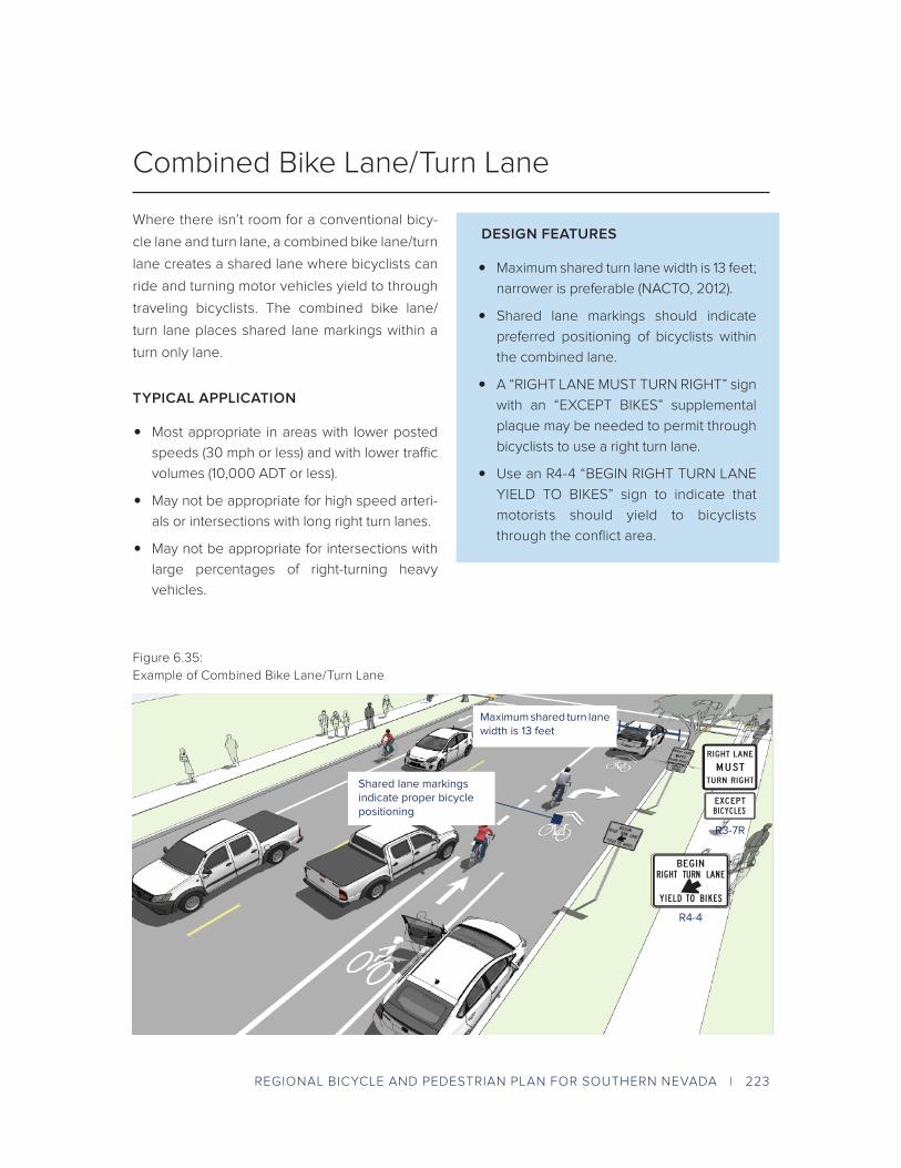
Figure 6.35:
Example of Combined Bike Lane/Turn Lane
Combined Bike Lane/Turn Lane
R4-4
Maximum shared turn lane width is 13 feet
Shared lane markings indicate proper bicycle positioning
R3-7R
DESIGN FEATURES
• Maximum shared turn lane width is 13 feet;
narrower is preferable (NACTO, 2012).
• Shared lane markings should indicate
preferred positioning of bicyclists within
the combined lane.
• A “RIGHT LANE MUST TURN RIGHT” sign
with an “EXCEPT BIKES” supplemental
plaque may be needed to permit through
bicyclists to use a right turn lane.
• Use an R4-4 “BEGIN RIGHT TURN LANE
YIELD TO BIKES” sign to indicate that
motorists should yield to bicyclists
through the conflict area.
Where there isn’t room for a conventional bicy-
cle lane and turn lane, a combined bike lane/turn
lane creates a shared lane where bicyclists can
ride and turning motor vehicles yield to through
traveling bicyclists. The combined bike lane/
turn lane places shared lane markings within a
turn only lane.
TYPICAL APPLICATION
• Most appropriate in areas with lower posted
speeds (30 mph or less) and with lower traffic
volumes (10,000 ADT or less).
• May not be appropriate for high speed arteri-
als or intersections with long right turn lanes.
• May not be appropriate for intersections with
large percentages of right-turning heavy
vehicles.

224 | REGIONAL BICYCLE AND PEDESTRIAN PLAN FOR SOUTHERN NEVADA
Bicycle pavement markings through intersec-
tions guide bicyclists on a safe and direct path
through the intersection and provide a clear
boundary between the paths of through bicy-
clists and vehicles in the adjacent lane.
TYPICAL APPLICATION
• Streets with conventional, buffered, or sepa-
rated bike lanes.
• At direct paths through intersections.
• Streets with high volumes of adjacent traffic.
• Where potential conflicts exist between
through bicyclist and adjacent traffic.
Figure 6.36:
Example of Intersection Crossing Markings
Intersection Crossing Markings
DESIGN FEATURES
• Intersection markings should be the same
width and in line with the leading bike
lane.
• Dotted lines should be a minimum of 6
inches wide and 4 feet long, longitudinally
spaced every 12 feet.
• All markings should be white, skid resis-
tant, and retro reflective.
• Green pavement markings may also be
used.

REGIONAL BICYCLE AND PEDESTRIAN PLAN FOR SOUTHERN NEVADA | 225
Figure 6.37:
Example of Mixing Zone
Mixing Zone
Short transition taper dimensions and vehicle storage length promote slower speeds
“Shark’s teeth” yield line prior to intersection
Shared lane markings indicate proper bicycle positioning
Mixing zone width varies (9 - 13’)
Transition to mixing zone should begin 70 feet prior to intersection
DESIGN FEATURES
• Use short transition taper dimensions
and short storage length to promote slow
motor vehicle travel speeds.
• The width of the mixing zone should be 9
feet minimum and 13 feet maximum.
• The transition to the mixing zone
should begin 70 feet in advance of the
intersection.
• Shared lane markings should be used
to illustrate bicyclists’ position within the
zone.
• A yield line should be used in advance of
the intersection.
A mixing zone creates a shared travel lane where
turning motor vehicles yield to through traveling
bicyclists. Geometric design is intended to slow
motor vehicles to bicycle speed, provide regu-
latory guidance to people driving, and require
all users to negotiate conflicts upstream of the
intersection.
TYPICAL APPLICATION
• Most appropriate in areas with low to moder-
ate right turning vehicular volumes.
• Streets with a right turn lane but not enough
width to have a standard width bicycle lane at
the intersection.

226 | REGIONAL BICYCLE AND PEDESTRIAN PLAN FOR SOUTHERN NEVADA
Loop Detectors. Bicycle-activated loop detec-
tors installed in the roadway trigger a change
in the traffic signal, allowing the bicyclist to stay
within the travel or bike lane without having
to maneuver to the roadside to push a button.
Loops that are sensitive enough to detect bicy-
cles should be supplemented with pavement
markings to instruct bicyclists how to trip them.
Video Detection Cameras. These systems use
digital image processing to detect an image
change at a location. These can be calibrated to
detect bicycles.
Remote Traffic Microwave Sensor Detection
(RTMS). Uses frequency-modulated continu-
ous wave radio signals to detect objects in the
roadway, which marks the detected object with
a time code to determine its distance from the
sensor. The RTMS system is unaffected by tem-
perature and lighting, which can affect standard
video detection.
TYPICAL APPLICATION
• Signalized intersections and where bicyclists
require crossing of a major street with high
vehicle speeds and/or traffic volumes where
a signal either exists or is needed.
• Where bicyclists are not currently detected or
where detection, actuation, or timing is inad-
equate to provide a safe and comfortable
crossing for users of all ages and abilities.
• Where bicycle ridership data needs to be
collected.
Detection and Signal Timing for Bicyclists
DESIGN FEATURES
• Recommend a minimum green time for
streets that do not possess bicycle detec-
tion that accommodates bicyclists travel-
ing at the 15th percentile speed using the
formula: minimum green time = 3 + (width
/ 14 ft/s)
• Shorter minimum green times should only
be utilized only when bicycle detection
is available, but not activated by a bicy-
clist. This may improve capacity and
reduce unnecessary wait times in some
scenarios.
In bike lane loop detection
RTMS
Video detection camera
Bicycle detector pavement marking(MUTCD Figure 9C-7)
Figure:
Types of Bicycle Detection

REGIONAL BICYCLE AND PEDESTRIAN PLAN FOR SOUTHERN NEVADA | 227
Protected bicycle lane crossings through signal-
ized intersections can be accomplished through
the use of a bicycle signal phase which reduces
conflicts with motor vehicles by separating bicy-
cle movements from any conflicting motor vehi-
cle movements, especially turns. Bicycle sig-
nals are traditional three-lens signal heads with
green, yellow, and red bicycle stenciled lenses.
Figure 6.39:
Example of Protected Bicycle Signal Phase
Protected Bicycle Signal Phase
TYPICAL APPLICATION
• Two-way separated bike lanes where contra-
flow bicycle movement or increased conflict
points warrant protected operation.
• Bicyclists moving on a green or yellow signal
indication in a bicycle signal shall not be in
conflict with any simultaneous motor vehicle
movement at the signalized location.
Exclusive/protected right-turn signal phase
R10-10B
• Right (or left) turns on red should be prohib-
ited in locations where such operation would
conflict with a green bicycle signal indication.
R10-11b
DESIGN FEATURES
• An additional “Bicycle Signal” sign should
be installed below the bicycle signal head.
• Designs for bicycles at signalized cross-
ings should allow bicyclists to trigger sig-
nals and safely maneuver the crossing.
• On bikeways, signal timing and actuation
shall be reviewed and adjusted to con-
sider the needs of bicyclists.

228 | REGIONAL BICYCLE AND PEDESTRIAN PLAN FOR SOUTHERN NEVADA
Figure 6.40:
Example of Bike Lanes at Channelized Turn Lanes
Preferred approach angle is no greater than 15 - 30 degrees
Colored pavement markings help denote conflict areas
Slip lane should be designed for slower travel speeds
Bike Lanes at Channelized Turn Lanes
DESIGN FEATURES
• The preferred angle of approach is no
more than 15-30 degrees.
• Design the turn radius of the right turn
lane to encourage appropriate decelera-
tion in preparation for yielding to crossing
pedestrians.
• Colored pavement markings should be
used at locations where motor vehicles
are directed to cross bicycle lanes.
Bicycle-friendly channelized turn lanes can
reduce the risk of potential conflicts between
bicyclists and turning vehicles by improving
sight lines of turning vehicles, slowing turning
vehicle speed, and reminding users of bicycle
priority in conflict areas.
TYPICAL APPLICATION
• At signalized intersections.
• Intersections with high right turn traffic vol-
umes, and very low levels of pedestrian
activity.
• Increase intersection efficiency for vehicles
and reduce delay at areas with high right-turn
traffic volumes.
• Wide streets with long crossing distances;
transition across bike lane should be as short
as possible to reduce bicyclist exposure.
• As an improvement to intersections with an
existing traditional channelized right-turn lane.

REGIONAL BICYCLE AND PEDESTRIAN PLAN FOR SOUTHERN NEVADA | 229
Some arterials may contain high speed free-
way-style designs such as merge lanes and exit
ramps, which can create difficulties for people
on bicycles. The entrance and exit lanes typi-
cally have intrinsic visibility problems because
of low approach angles and high speed differ-
entials between bicyclists and motor vehicles.
Strategies to improve safety focus on increasing
sight distances, creating formal crossings, and
minimizing crossing distances.
TYPICAL APPLICATION
• Streets with high speed freeway style merge
lanes.
• Where users are skilled adult riders.
• Design strategies differ for low-speed and
high-speed configurations.
Figure:
Example of Bike Lanes at Entrance and Exit Ramp
Crossing located in location with lowest speed and highest visibility
Crossing located before drivers’ attention is focused on the upcoming merge
Main St
Industrial Dist
Waterfront
0.1 MI. 1 MIN.
2.0 MI. 15 MIN.
3.0 MI. 20 MIN.
W11-1 W11-1
R1-2
R1-2
Wayfinding signage should clarify path to destinations
Ramp geometrics minimize speed for exiting vehicles
Bike Lanes at Entrance and Exit Ramps
DESIGN FEATURES
• On low-speed entrance ramps (≤ 35 mph), the
bike lane should travel straight through the
merge area. Use dotted lines, colored pave-
ment, and signs to define bicyclist priority over
merging traffic.
• At high-speed entrance ramps (≥ 40 mph),
with dedicated receiving lanes, bicyclists
should be encouraged to yield to merging traf-
fic and cross when safe. Angle the bike lane
to increase the approach angle with entering
traffic and position the crossing before the
drivers’ attention is focused on the upcoming
merge.
• On low-speed exit ramps (≤ 40 mph), the bike
lane should travel straight through the merge
area. Use dotted lines, colored pavement, and
signs to define bicyclist priority.
• On high-speed exit ramps (≥ 45 mph), use a 45
foot (35 foot minimum) jug handle turn to bring
bicyclists to a visible location with exiting traf-
fic and a 45 foot (35 foot minimum) taper from
roadway.

230 | REGIONAL BICYCLE AND PEDESTRIAN PLAN FOR SOUTHERN NEVADA
Figure 6.42:
Example of “Toucan” Signal
Push button activation
Stop lines, crosswalks, and green pavement markings help clarify crossing behaviors.
Minor cross street is controlled by STOP sign.
R10-10B
Toucan signal assembly pairs bicycle and pedestrian signal heads
“Toucan” Signal
DESIGN FEATURES
• A toucan signal assembly may be created by
pairing a bicycle signal head with a pedestrian
signal head.
• If located at an intersection, the major street
receives standard traffic signal control, and
the minor cross street has a STOP sign to
control motor vehicle traffic. The design may
be paired with access management or other
measures to reduce potential motor vehi-
cle-bicycle and motor vehicle-pedestrian
conflicts.
• The walking and bicycling phase is typically
activated by a push button or by passive
detection.
• Stop lines, high visibility crosswalk markings,
and bicycle lane dotted line extensions should
be used to clarify crossing expectations.
• Green colored pavement may be used to
highlight the bike lane crossing.
“Toucan” crossings of streets are a type of sig-
nal configuration that provides minor street or
mid-block signal indication for bicyclists and
pedestrians, but not for motor vehicles, so that
“two can” cross the major street.
TYPICAL APPLICATION
• Appropriate at mid-block or carefully designed
intersection locations.
• Across higher traffic streets where pedestri-
ans and bicyclists are crossing together.
• Across higher traffic streets where a conven-
tional traffic signal or pedestrian hybrid bea-
con is considered to assist in pedestrian and
bicyclist crossings.

REGIONAL BICYCLE AND PEDESTRIAN PLAN FOR SOUTHERN NEVADA | 231
W11-15
A protected intersection uses a collection of
intersection designs that maximize user com-
fort within the intersection and promote a high
rate of yielding to people bicycling. The design
is based on a setback bikeway crossing using
physical separation within the intersection to
define the turning paths of motor vehicles, slow
motor vehicle turning speed, and offer a com-
fortable refuge for people bicycling and walking
while waiting at a red signal.
TYPICAL APPLICATION
• At signalized intersections along streets with
separated bicycle lanes.
• At signalized intersections along streets with
other bikeway types, provided that the bike-
way transitions into a separated bicycle lane
just upstream of the intersection
• Connecting two or more appropriate Regional
Active Transportation Network facilities.
• Along crossings of major or minor streets to
slow vehicles and increase yielding.
• At corner locations where pedestrian curb
extensions are desired.
Figure 6.43:
Example of Protected Intersection
W11-15
Protected Intersections
DESIGN FEATURES
• Setback bicycle crossing of 20 feet allows
for one passenger car to queue while
yielding. A larger setback is desired in
high speed areas (> 35 mph). Smaller set-
back distance is possible in slow-speed,
constrained conditions.
• Corner safety island with a 15-20 foot cor-
ner radius slows motor vehicle speeds.
Larger radius designs may be possible
when paired with a deeper setback or a
protected signal phase.
• A forward stop bar should indicate the
area for people bicycling to wait at a red
signal.
• If a permissive left turn is allowed, a
median island extending into the inter-
section should be used to channelize and
direct left turning motor vehicles.
• Intersection crossing markings should
be used to identify the bicycle crossing.
Consider green pavement to highlight the
crossing area.

232 | REGIONAL BICYCLE AND PEDESTRIAN PLAN FOR SOUTHERN NEVADA
Figure 6.44:
Example of Single Lane Roundabout with Bicycle and Pedestrian Crossings & Infrastructure
In single lane roundabouts it is important to
indicate to motorists, bicyclists and pedestri-
ans the right-of-way rules and correct way for
them to circulate, using appropriately designed
signage, pavement markings, and geometric
design elements.
TYPICAL APPLICATION
• Where a bike lane or separated bikeway
approaches a single-lane roundabout.
Single Lane Roundabouts
DESIGN FEATURES
• 25 mph maximum circulating design speed
• Design approaches/exits to the lowest speeds
possible.
• Encourage bicyclists navigating the round-
about like motor vehicles to “take the lane.”
• Maximize yielding rate of motorists to pedes-
trians and bicyclists at crosswalks.
• Provide separated facilities for bicyclists who
prefer not to navigate the roundabout on the
roadway.
W11-15
Crossings set back at least one car length from the entrance of the roundabout; crossings shall utilize splitter islands as refuge areas
Bicycle entrance ramp in line with bicycle lane
Visible, well marked crossings alert motorists to the presence of bicyclists and pedestrians (W11-15 signage)
Narrow circulating lane to discourage attempted passing and promote slower circulating speeds
Truck apron can provide adequate clearance for longer vehicles
Separate pedestrian and bicycle traffic through sidewalk and adjacent bike lanes
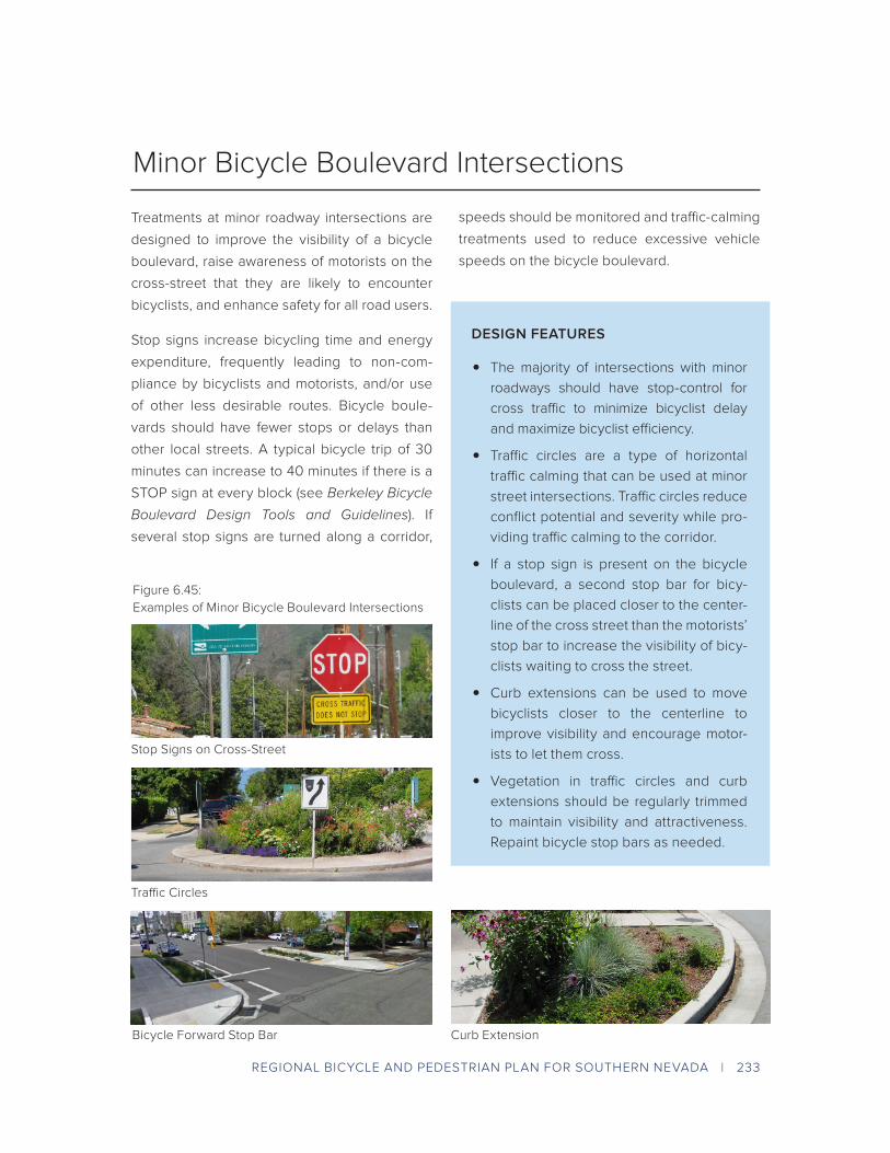
REGIONAL BICYCLE AND PEDESTRIAN PLAN FOR SOUTHERN NEVADA | 233
Treatments at minor roadway intersections are
designed to improve the visibility of a bicycle
boulevard, raise awareness of motorists on the
cross-street that they are likely to encounter
bicyclists, and enhance safety for all road users.
Stop signs increase bicycling time and energy
expenditure, frequently leading to non-com-
pliance by bicyclists and motorists, and/or use
of other less desirable routes. Bicycle boule-
vards should have fewer stops or delays than
other local streets. A typical bicycle trip of 30
minutes can increase to 40 minutes if there is a
STOP sign at every block (see Berkeley Bicycle
Boulevard Design Tools and Guidelines). If
several stop signs are turned along a corridor,
speeds should be monitored and traffic-calming
treatments used to reduce excessive vehicle
speeds on the bicycle boulevard.
Minor Bicycle Boulevard Intersections
DESIGN FEATURES
• The majority of intersections with minor
roadways should have stop-control for
cross traffic to minimize bicyclist delay
and maximize bicyclist efficiency.
• Traffic circles are a type of horizontal
traffic calming that can be used at minor
street intersections. Traffic circles reduce
conflict potential and severity while pro-
viding traffic calming to the corridor.
• If a stop sign is present on the bicycle
boulevard, a second stop bar for bicy-
clists can be placed closer to the center-
line of the cross street than the motorists’
stop bar to increase the visibility of bicy-
clists waiting to cross the street.
• Curb extensions can be used to move
bicyclists closer to the centerline to
improve visibility and encourage motor-
ists to let them cross.
• Vegetation in traffic circles and curb
extensions should be regularly trimmed
to maintain visibility and attractiveness.
Repaint bicycle stop bars as needed.
Stop Signs on Cross-Street
Traffic Circles
Bicycle Forward Stop Bar Curb Extension
Figure 6.45:
Examples of Minor Bicycle Boulevard Intersections

234 | REGIONAL BICYCLE AND PEDESTRIAN PLAN FOR SOUTHERN NEVADA
The quality of treatments at major street cross-
ings can significantly affect a bicyclist’s choice to
use a bicycle boulevard, as opposed to another
road that provides a crossing treatment.
Maintain signs, markings, and other treatments
and replace as needed. Monitor intersections
for bicyclist delay to determine if additional
treatments are warranted.
TYPICAL APPLICATION
• Bicycle boulevard retrofits to local streets
are typically located on streets without exist-
ing signalized accommodation at crossings
of collector and arterial roadways. Without
treatments for bicyclists, these intersections
can become major barriers along the bicycle
boulevard and compromise safety.
Major Bicycle Boulevard Intersections
DESIGN FEATURES
• Bike boxes increase bicyclist visibility to
motorists and reduce the danger of right
“hooks” by providing a space for bicyclists
to wait at signalized intersections.
• Median islands provided at uncontrolled
intersections of bicycle boulevards and
major streets allow bicyclists to cross one
direction of traffic at a time as gaps in traf-
fic occur.
• Hybrid beacons, active warning beacons
and bicycle signals can facilitate bicyclists
crossing a busy street on which cross-traf-
fic does not stop.
• Select treatments based on engineer-
ing judgment; see National Cooperative
Highway Research Program (NCHRP)
Report # 562 Improving Pedestrian
Safety at Unsignalized Crossings (2006)
for guidance on appropriate use of cross-
ing treatments. Treatments are designed
to improve visibility and encourage
motorists to stop for pedestrians; with
engineering judgment many of the same
treatments are appropriate for use along
bicycle boulevards.
Bike Box
Median Island
Hybrid Beacon (HAWK) Rectangular Rapid Flash Beacon (RRFB)
Figure 6.46:
Examples of Major Bicycle Boulevard Intersections