chapter 6 delivery and forwarding of ip...
TRANSCRIPT
1Kyung Hee University
Chapter 6Delivery and
Forwarding of IP Packets
2Kyung Hee University
6.1 Delivery
The network layer supervises the handling of the packets by the underlying physical networks.
This handling is called as delivery of a packet
The delivery of a packet to its final destination is accomplished using two different methods of delivery : direct and indirect

3Kyung Hee University
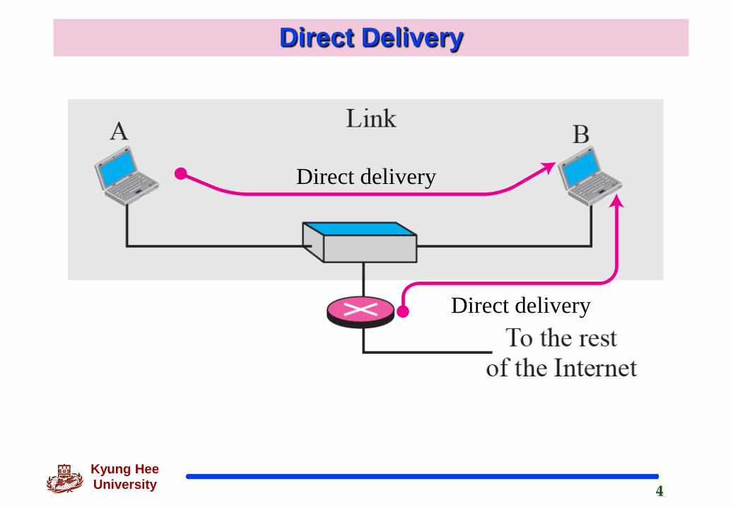
Direct DeliveryThe final destination of the packet is a host connected to the
same physical network as the deliverer.
Source and destination of the packet are located on the same physical network
Delivery between last router and the destination host
Extract the network address of the destination and compare this address with the addresses of the networks to which it is connected
If a match is found, the delivery is direct
The sender uses the destination IP address to find the destination physical address
4Kyung Hee University
Direct Delivery
Direct delivery
Direct delivery

5Kyung Hee University
Indirect Delivery
The destination host in not on the same network as the delivery
The packet goes from router to router until it reaches the one connected to the same physical network
The sender uses the destination IP address and a routing table to find IP address of the next router

6Kyung Hee University
Indirect Delivery
Link LinkLink
A B
Indirect delivery Indirect delivery Direct delivery

7Kyung Hee University
6.2 Forwarding
Forwarding means to place the packet in its route to its destination
Since the Internet today is made of a combination of links, forwarding means to deliver the packet to the next hop
Although IP protocol was originally designed as a connectionless protocol, today the tendency is to use IP as a connection-oriented protocol based on the label attached to an IP datagram

8Kyung Hee University
Forwarding
Forwarding based on destination address
Next-hop
Network- Specific Method
Host-Specific Method
Default Method
Forwarding Based on Label

9Kyung Hee University
Next-Hop Method
One technique to reduce the contents of a routing table
The routing table holds only the address of the next hop instead of information about the complete route

10Kyung Hee University
Network Specific Method
Reduce the routing table and simplify the searching process
The routing table has only one entry that defines the address of the destination network itself
N2 R1Destination Next Hop
Network-specificrouting table for host S
ABCD
DestinationR1R1R1R1
Next Hop
Host-specificrouting table for host S

11Kyung Hee University
Host-Specific Method The Destination host address is given in the routing table
Inverse of network-specific method
When administrator wants to have more control
R2
Host B
R3
Host A
R1
N1
N2 N3
Routing table for host A
R3R1R3
......
Destination Next HopHost B
N2N3......
12Kyung Hee University
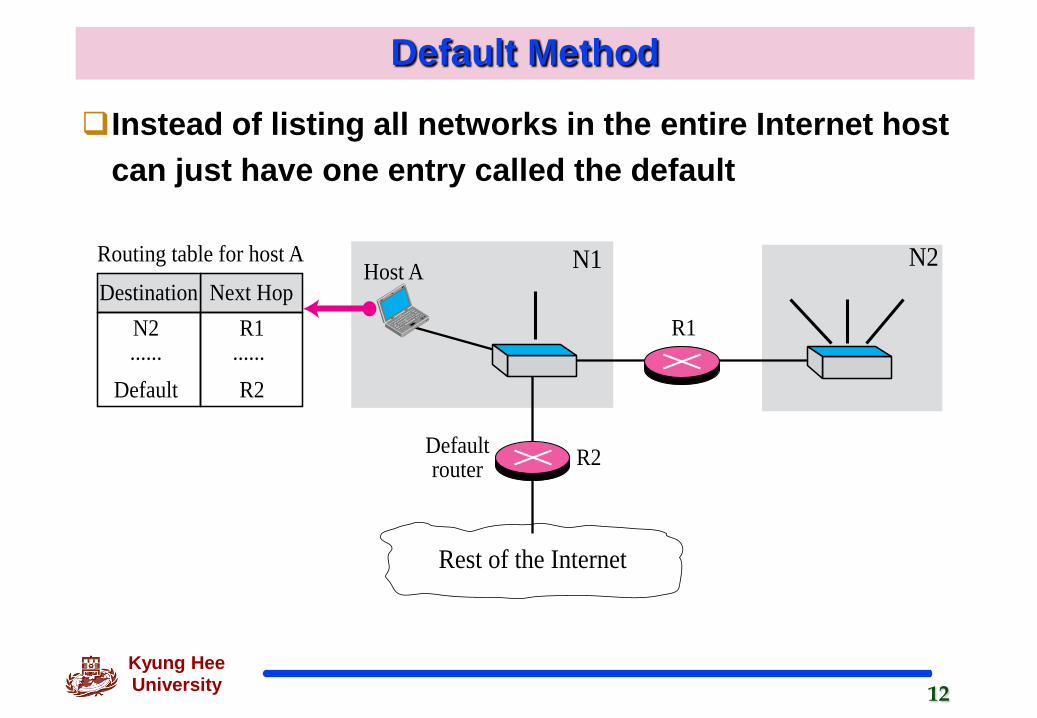
Default Method
Instead of listing all networks in the entire Internet host can just have one entry called the default
R1
Host A N1
Rest of the Internet
Defaultrouter R2
N2Routing table for host A
Destination Next Hop
......N2
Default......R1
R2
13Kyung Hee University
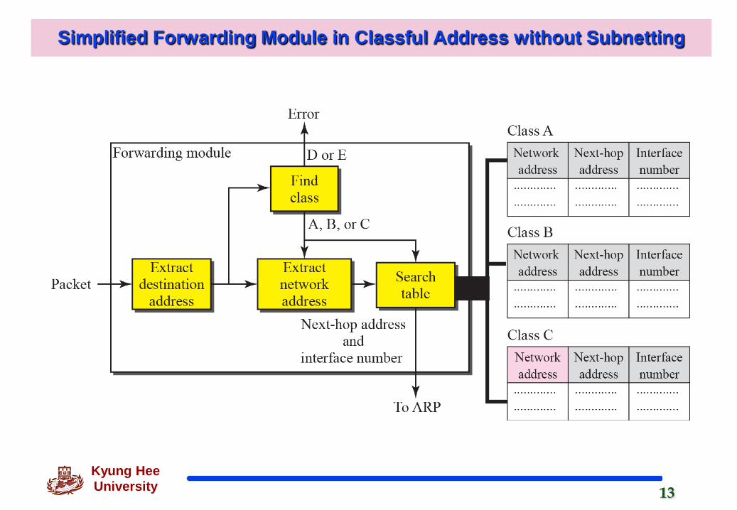
Simplified Forwarding Module in Classful Address without Subnetting
14Kyung Hee University
Example 6.1
Figure 6.8 shows an imaginary part of the Internet. Show the routing tables for router R1.
Solution
Figure 6.9 shows the three tables used by router R1. Note that some entries in the next-hop address column are empty because in these cases, the destination is in the same network to which the router is connected. In these cases, the next-hop address used by ARP is simply the destination address of the packet as we will see in Chapter 8.

15Kyung Hee University
Figure 6.8 Configuration for routing

16Kyung Hee University
: Figure 6.8 : Table for Example 6.1
17Kyung Hee University
Example 6.2
Router R1 in Figure 6.8 receives a packet with destination address 192.16.7.14. Show how the packet is forwarded.
Solution
The destination address in binary is 11000000 00010000 00000111 00001110. A copy of the address is shifted 28 bits to the right. The result is 00000000 00000000 00000000 00001100 or 12. The destination network is class C. The network address is extracted by making off the left-most 24 bits of the destination address; the result is 192.16.7.0. The table for Class C is searched. The network address is found in the first row. The next-hop address 111.15.17.32 and the interface m0 are passed to ARP(see Chapter 8)

18Kyung Hee University
Simplified Forwarding Module in Classful Address with Subnetting

19Kyung Hee University
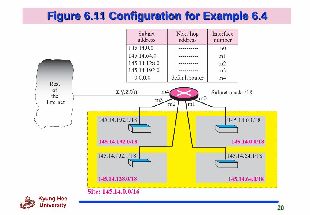
Example 6.4
Figure 6.11 shows a router connected to four subnets. Note several points. First, the site address is 145.14.0.0/16 (a class B address). Every packet with destination address in the range 145.14.0.0 to 145.14.255.255 is delivered to the interface m4 and distributed to the final destination subnet by the router. Second, we have used the address x.y.z.t/n for the interface m4 because we do not know to which network this router is connected. Third, the table has a default entry for packets that are to be sent out of the site. The router is configured to apply the subnet mask /18 to any destination address
20Kyung Hee University
Figure 6.11 Configuration for Example 6.4
21Kyung Hee University
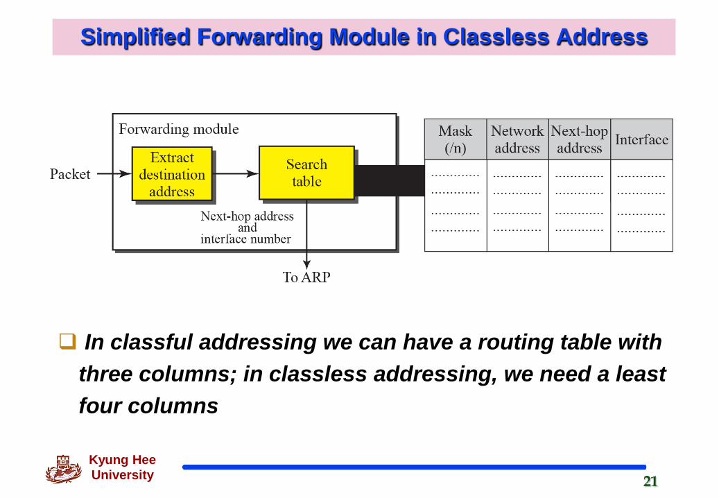
Simplified Forwarding Module in Classless Address
In classful addressing we can have a routing table with three columns; in classless addressing, we need a least four columns
22Kyung Hee University
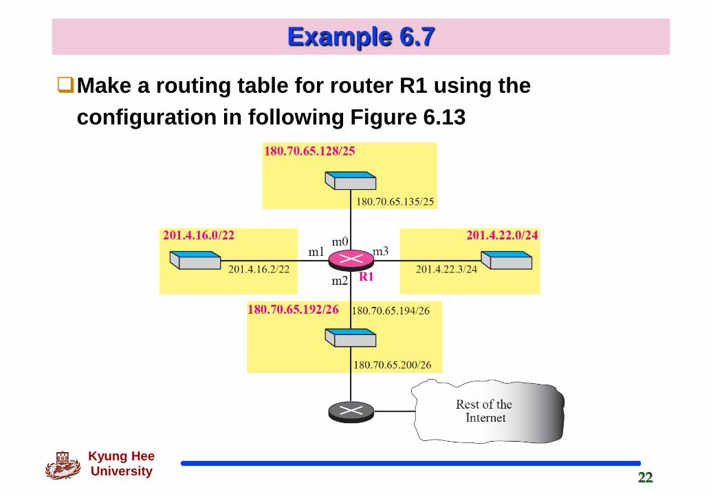
Example 6.7
Make a routing table for router R1 using the configuration in following Figure 6.13

23Kyung Hee University
Routing Table for router R1 in previous Figure
Solution
Mask Network Address Next Hop Interface
/26 180.70.65.192 - m2
/25 180.70.65.128 - m0
/24 201.4.22.0 - m3
/22 201.4.16.0 …. m1
Default Default 180.70.65.200 m2

24Kyung Hee University
Example 6.8
Show the forwarding process if a packet arrives at R1 in Figure 6.13 with the destination address 180.70.65.140.
Solution
The router performs the following steps:
1. The first mask(/26) is applied to the destination address. The result is 180.70.65.128, which does not match the corresponding network address.
2. The second mask(/25) is applied to the destination address. The result is 180.70.65.128, which matched the corresponding network address. The next-hop address and the interface number m0 are passed to ARP
25Kyung Hee University
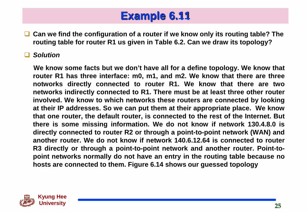
Example 6.11 Can we find the configuration of a router if we know only its routing table? The
routing table for router R1 us given in Table 6.2. Can we draw its topology?
Solution
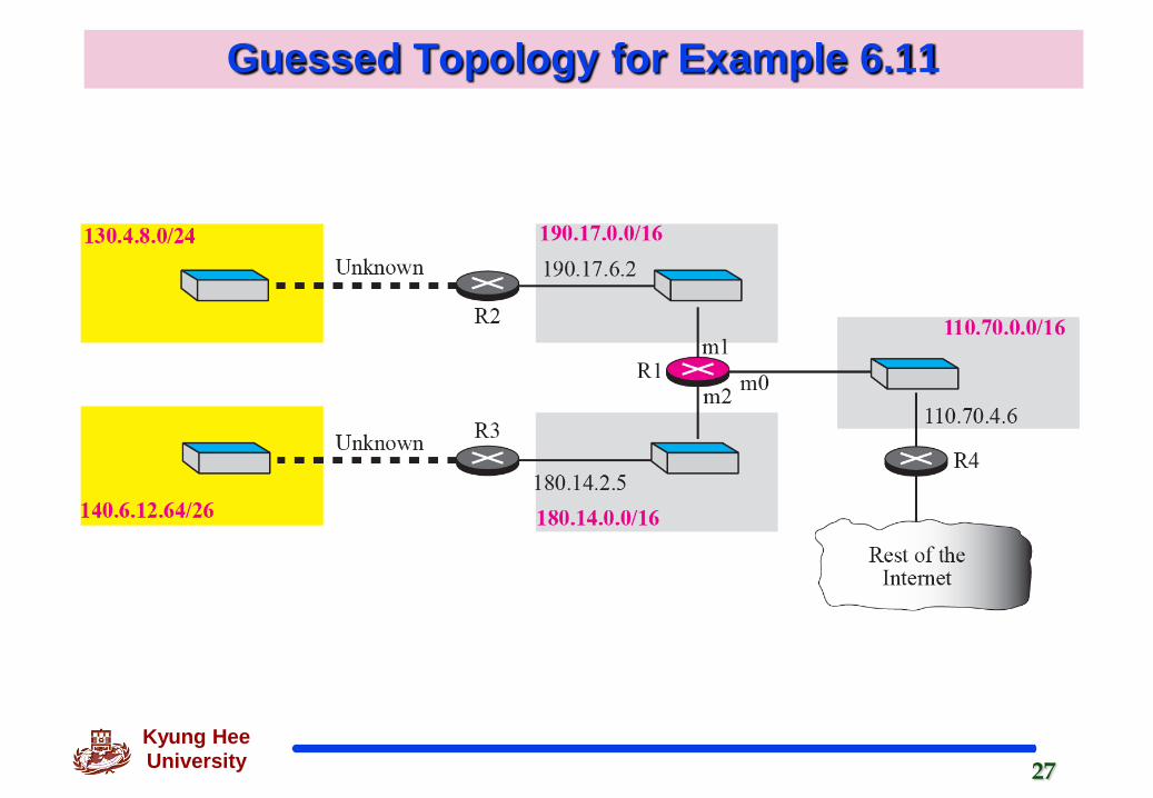
We know some facts but we don’t have all for a define topology. We know thatrouter R1 has three interface: m0, m1, and m2. We know that there are threenotworks directly connected to router R1. We know that there are twonetworks indirectly connected to R1. There must be at least three other routerinvolved. We know to which networks these routers are connected by lookingat their IP addresses. So we can put them at their appropriate place. We knowthat one router, the default router, is connected to the rest of the Internet. Butthere is some missing information. We do not know if network 130.4.8.0 isdirectly connected to router R2 or through a point-to-point network (WAN) andanother router. We do not know if network 140.6.12.64 is connected to routerR3 directly or through a point-to-point network and another router. Point-to-point networks normally do not have an entry in the routing table because nohosts are connected to them. Figure 6.14 shows our guessed topology

26Kyung Hee University
Routing Table for Example 6.11 : Table 6.1
Mask Network Address Next HopAddress
InterfaceNumber
/26 140.6.12.64 180.14.2.5 m2
/24 130.4.8.0 190.17.6.2 m1
/16 110.70.0.0 - m0
/16 180.14.0.0 - m2
/16 190.17.0.0 - m1
Default Default 110.70.4.6 m0
27Kyung Hee University
Guessed Topology for Example 6.11

28Kyung Hee University
Address Aggregation
The increased size of the table results in an increase in the amount of time needed to search the table
29Kyung Hee University
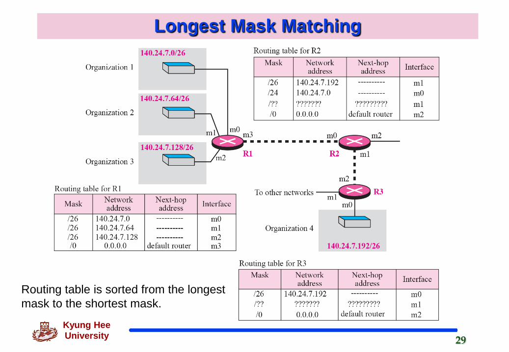
Longest Mask Matching
Routing table is sorted from the longestmask to the shortest mask.
30Kyung Hee University
Routing
Hierachical Routing
To solve the problem of gigantic routing table.
If the routing table has a sense of hierarchy like the Internet architecture, the routing table can be decrease in size
Geographical Routing
Divide the entire address space into a few large block- US, EU, Asia, Africa and so on
Routing table search algorithms
See the Chapter 11

31Kyung Hee University
Example 6.12
As an example of hierarchical routing, let us consider Figure 6.17. A regional ISP is a granted 16,384 addresses starting from 120.14.64.0. The regional ISP has decided to divided to divide this block into 4 subblocks, each with 4096 addresses. Three of these subblock are assigned to three local ISPs, the second subblock is reserved for future use. Note that the mask for each block is /20 because the original block with mask /18 is divided into 4 blocks.

32Kyung Hee University
Hierarchical Routing with ISPs
33Kyung Hee University
Forwarding Based on Label
Change IP to behave like a connection-oriented protocol in witch the routing is replaced by switching
34Kyung Hee University
Example 6.13
Figure 6.18 shows a simple example of searching in a routing table using the longest match algorithm. Although there are some more efficient algorithms today, the principle is the same. When the forwarding algorithm gets the destination address of the packet, it needs to delve into the mask column. For each entry, it needs to apply the mask to find the destination network address. It then needs to check the network addresses in the table until it finds the match. The router then extracts the next-hop address and the interface number to be delivered to the ARP protocol for delivery of the packet to the next hop.

35Kyung Hee University
Figure 6.18 : Forwarding based on Destination Address
Next-hopaddress InterfaceNetwork
addressMask�(/n)
NF
NF
NFNFNFNFNFNFF
F
323231313131313029
2
0
1
2
Routing Table
Legend
: Compare:Not found
:Found
y
36Kyung Hee University
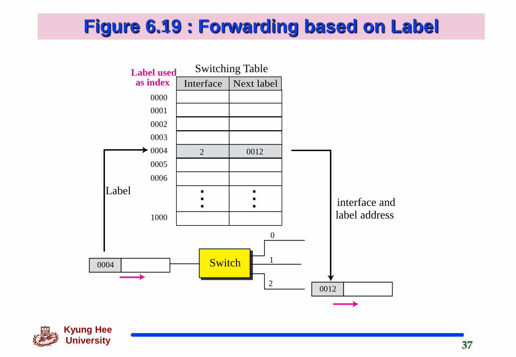
Example 6.14
Figure 6.19 shows a simple example of using a label to access a switching table. Since the labels are used as the index to the table, finding the information in the table is immediate.
37Kyung Hee University
Figure 6.19 : Forwarding based on Label
Interface Next label000000010002
1
0
2
00030004 200050006
1000
Switching TableLabel usedas index
0012
Switch0004
Labelinterface andlabel address
0012

38Kyung Hee University
MPLS(Multi-Protocol Label Switching)
During the 1980s, several vendors created routers that implement switching technology.
When behaving like a router, MPLS can forward the packet based on the destination address; when behaving like a switch, it can forward a packet based on label.
A new header is needed
MPLS header added to an IP packet
39Kyung Hee University
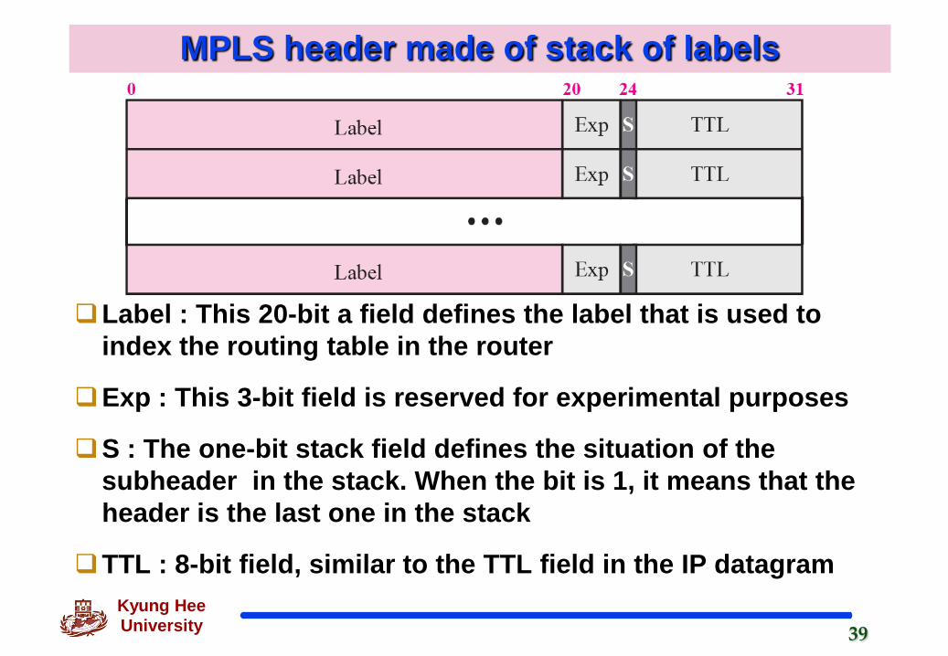
MPLS header made of stack of labels
Label : This 20-bit a field defines the label that is used to index the routing table in the router
Exp : This 3-bit field is reserved for experimental purposes
S : The one-bit stack field defines the situation of the subheader in the stack. When the bit is 1, it means that the header is the last one in the stack
TTL : 8-bit field, similar to the TTL field in the IP datagram
40Kyung Hee University
6.3 Structure of a Router
Router is
Black box that accepts incoming packets, uses a routing table to find the output port, and sends the packets
In this section,
Open the black box and look inside.
But this is a just an review and our discussion will not be very detaoled.

41Kyung Hee University
Router Component
42Kyung Hee University
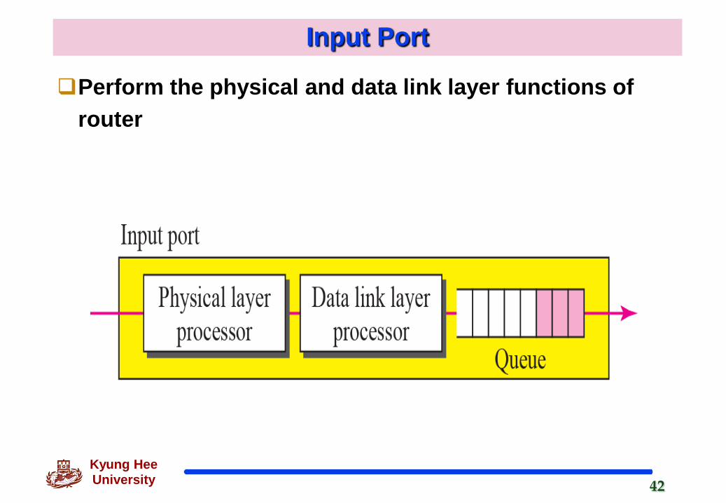
Input Port
Perform the physical and data link layer functions of router
43Kyung Hee University
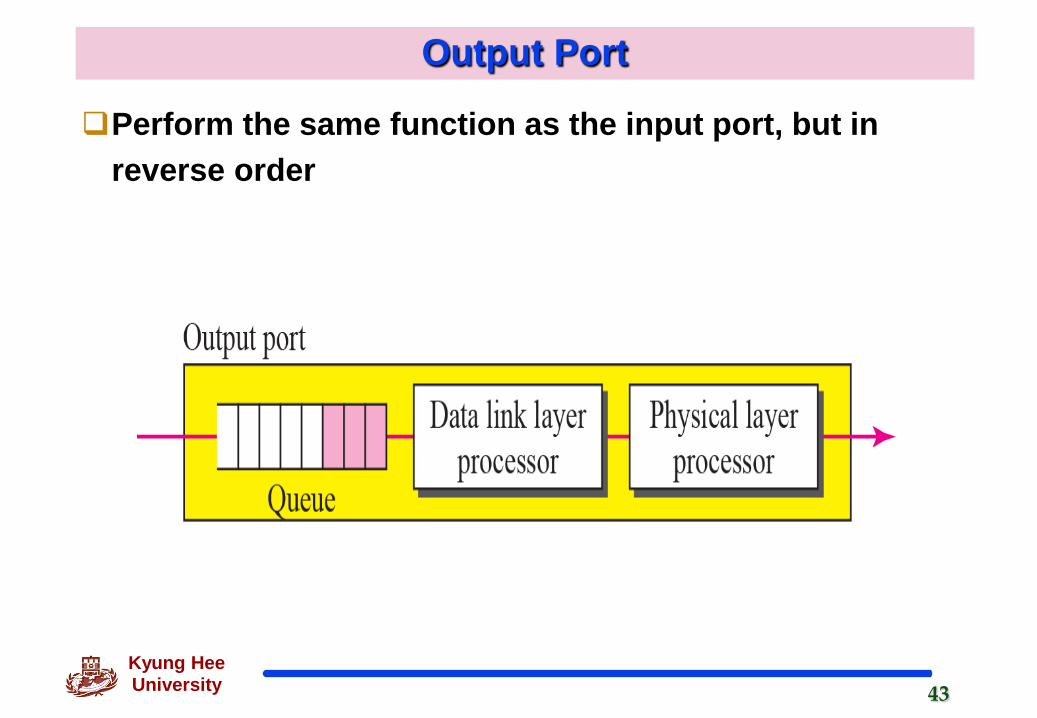
Output Port
Perform the same function as the input port, but in reverse order

44Kyung Hee University
Routing Processor and Switching Fabric
Routing Processor
Perform the functions of the network layer
The destination address is used to find the address of next hop and the output port number from which the packet is sent out
Switching Fabric
The most difficult task in a router
Move the packet from the input queue to output queue
Routers use a variety of switching fabrics

45Kyung Hee University
Crossbar Switch
Connects n inputs to n outputs in a grid
Using electronic microswitches at each cross point
46Kyung Hee University
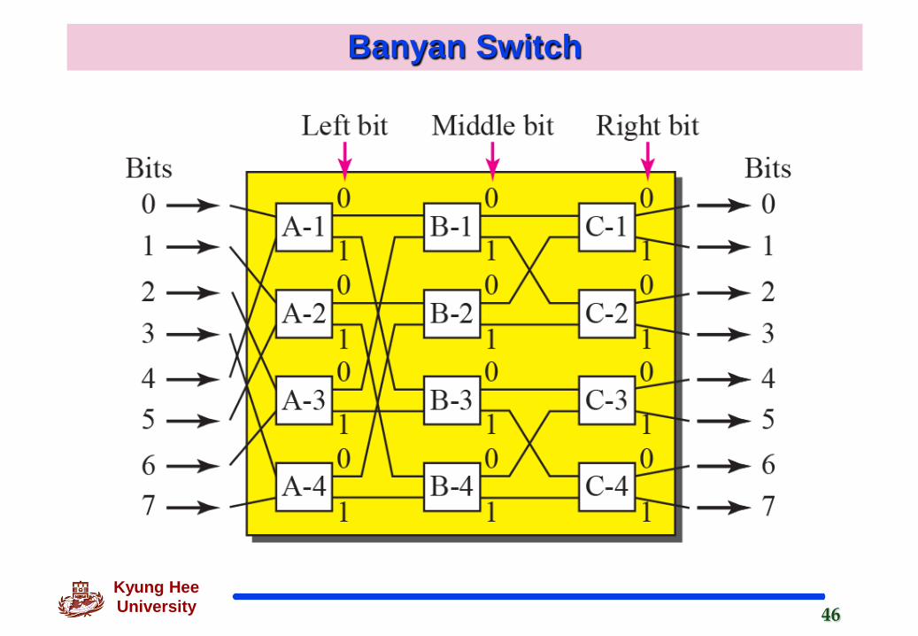
Banyan Switch
47Kyung Hee University
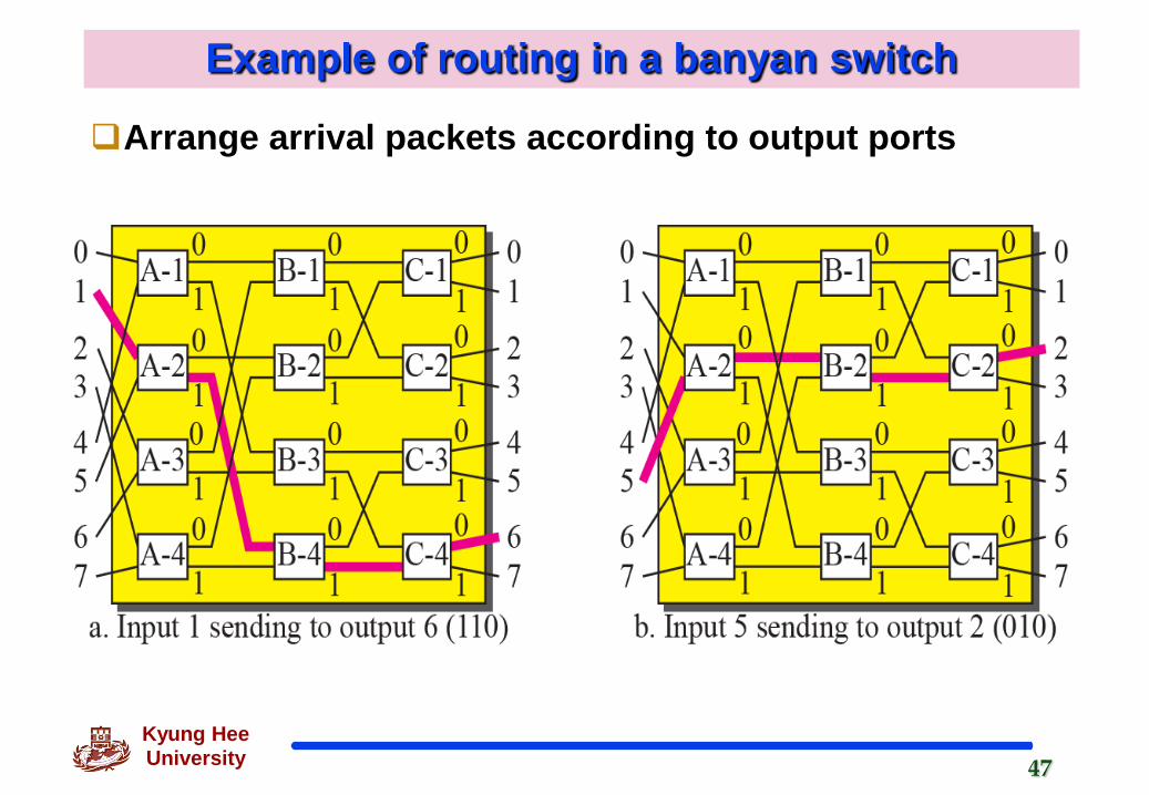
Example of routing in a banyan switch
Arrange arrival packets according to output ports

48Kyung Hee University
Batcher-banyan Switch