chapter 6: cvt drive and brake system -...
TRANSCRIPT

CVT DRIVE AND BRAKE SYSTEM
93
About this chapter
The drive and brake systems for the Cub Cadet Series 1000 tractor are combined. Two reasons for this:
• The brake on the Series 1000 tractor is supplied with the transaxle.
• The brake pedal applies the brake and disengages the drive system. Both systems share common link-age.
The transaxle used in the Cub Cadet Series 1000 is a relatively simple gearbox containing forward, neutral, and reverse gears. The variation in speed is all handled by the variable speed pulley system that drives the transaxle.
If the tractor has drive system problems within the warranty period, the servicing Cub Cadet dealer has the fol-lowing responsibilities:
• Eliminate any external causes for drive system problems before removing the transmission from the trac-tor.
• External problems would include, but are not limited to: belt, linkage, or brake issues.
• Look for signs of over-use or abuse. Transaxles that fail because of over use or abuse are not warrant-able. They are to be repaired or replaced at the customer’s expense.
• If the problem is internal, the transmission is to be replaced under the like-kind exchange policy.
• If a transaxle is replaced under warranty, the original transaxle may be called-back for evaluation by MTD Vendor Recovery Dept.
• Warranty Claims will be denied, returned, or adjusted if the returned transaxle does not meet Cub Cadet’s replacement criteria.
• Dealers are encouraged to open transaxles for inspection, allowing them to identify a problem within the transaxle.
• Beyond warranty, dealers are free to repair transmissions at customer expense.
• If the dealer has questions regarding transaxle replacement, they should call Cub Cadet Service using the dealer only line before proceeding.
About the variable speed drive system.
There are two drive belts in the system. A long drive belt transfers power from the engine crankshaft to the lower sheave of the variable-speed pulley. A shorter belt fits in the upper sheave of the variable speed pulley; transferring power from there to the input pulley on the transaxle.
• The drive control pedal tensions the front drive belt.
• The center partition of the variable speed pulley separates the lower (front) belt from the upper (rear) belt.
• As the front belt is tensioned, it is drawn deeper into its sheave. The effective circumference of the driven pulley shrinks.
• As the front belt is drawn deeper into its sheave, the center partition is forced upward, making the upper shave narrower.
• As the upper sheave pinches-down on the rear drive belt, the belt is forced outward in the sheave. The effective circumference of the pulley driving the rear belt grows.
• As the upper and lower sheaves change size, the drive ratio shifts increasing the speed of the rear belt.
• As the sheave that drives the rear belt changes size, the belt must be kept under constant tension. A ten-sion idler pulley accomplishes this task.
• The clutch/brake pedal automatically de-tensions the front belt when it is applied.
CHAPTER 6: CVT DRIVE AND BRAKE SYSTEM

LTX Tractors
94
Externally repairable drive system problems:
Most of the problems listed in this section will result in a customer complaint of low power or low ground speed. If the tractor is difficult to push, check the brakes.
1. Engine performance:
• If the engine does not turn at the specified RPM, the tractor will not travel at its designed speed. See Figure 6.1.
• If the engine does not produce the specified amount of power, the tractor will not have its designed amount of tractive force.
1a. Find the specified engine RPM for the tractor ( 3,375-3,525 RPM for the Cub Cadet Series 1000).
1b. Check the engine with a tachometer to con-firm that it maintains the specified RPM under normal load.
1c. Correct engine performance problems before trying to diagnose drive system problems.
2. Check the tires: Confirm that the correct size tires are on the tractor.
Smaller rear tires will yield lower ground speed. Under-filled tires will put additional load on the drive system.
• LTX 1040 Series has 20” x 8” rear tires.
• LTX 1050 Series has 20” x 10” rear tires.
• SLTX 1050 Series has 22” x 9.5” rear tires.
3. Check the brakes: See Figure 6.2.
3a. The brake linkage applies the brakes and dis-engages the drive belt. Confirm that both parts of the linkage are moving properly.
• When the brake pedal is released, the front drive belt should be slightly slack.
• The drive and brake linkages are connected in such a way that the pedals will “see-saw”, and it should not be possible to apply drive and clutch/brake pedal at the same time.
Figure 6.1
Figure 6.2

CVT DRIVE AND BRAKE SYSTEM
95
3b. If the linkage is working properly, but the brakes seem to be dragging, check the brake yoke. The linkage is not adjustable. See Figure 6.3.
• When the brakes are released, it should be possi-ble to wiggle the brake rotor within the yoke.
• If the rotor is tight in the caliper, check the yoke adjustment.
• If the rotor is tight in the yoke, check the operation of the yoke to confirm that it is not stuck.
• When the brake pedal is released, the brake arm on the yoke should fall completely back against the axle housing.
4. Check the drive belts. See Figure 6.4.
• In normal use, drive belts typically last for years without problems.
• If the belt fails prematurely, identify and correct the cause of the belt failure before returning the tractor to service.
4a. Look-up the part number for the belts, and con-firm that the correct OEM belts are on the trac-tor.
4b. Check the belt routing.
4c. Check the brake/clutch linkage and belt ten-sioning pulleys.
4d. Check for foreign objects jammed against the belt.
4e. Check for missing or out-of-place belt guides. See the belt replacement section of this chap-ter.
4f. Check the engine crankshaft and transaxle input pulleys; Confirm that the sheaves are not spread-out, causing a loose belt fit.
Figure 6.3
Brake yoke
Figure 6.4

LTX Tractors
96
5. Check the drive control linkage. See Figure 6.5.
5a. The travel limit pin fits into the curved slot in the drive pedal latch plate. The pedal bracket should have enough travel for the pin to hit both ends of the curved slot when the pedal is moved through the full range of its travel.
5b. Some relatively simple things that may go wrong with the pedal linkage:
• The drive pedal itself being loose on the bracket.
• Worn plastic bushings between the drive pedal bracket and the brake cross-shaft. See Figure 6.6.
5c. Check the adjustment of the front tensioner pulley control rod.
6. Transaxle mounting: See Figure 6.7.
6a. The primary symptoms of a transaxle that is loose in the frame are that it will lose drive or throw-off the upper drive belt in reverse.
6b. Check the torque bracket and the axle mount-ing points at the frame.
7. If there is no drive in either direction, check the gear selector adjustment.
Figure 6.5
Travel limit pin
Figure 6.6
Plastic bushing
Pedal mounting bracket
Figure 6.7
Torque bracket bolts

CVT DRIVE AND BRAKE SYSTEM
97
Indications that a transaxle is not warrantable
Anything that would indicate misuse, abuse, neglect, accident, improper maintenance, alteration, vandalism, theft, fire, water or damage because of other peril or natural disaster will render the transaxle non-warrantable even though it is within the normal warranty period.
Typical indicators of a void warranty would be:• The normal warranty is for 3 years or 120 hours, whichever comes first. Beyond 120 hours of use, the
tractor is out of warranty• Abnormally high wear indicators for the age of the tractor (usually consistent with high hours of usage). As
an example, if the tires are completely worn-out on a tractor that is 6-months old, it is reasonable to think it has been used pretty heavily even if the hour meter has been unplugged.
• Bent axle, broken housing, or other obvious signs of impact damage• Contaminated fluid or low fluid• Damage to the cooling fan• Indication that the tractor has been overloaded.
Brake adjustment
1. Test the operation of the brakes: See Figure 6.8.
1a. Put the transaxle in neutral.
1b. Set the parking brake by depressing the brake/clutch pedal and pushing-down on the parking brake/cruise control lever.
1c. Attempt to push the tractor. If it can be pushed by hand without skidding a rear wheel, check and adjust the brakes.
1d. Release the parking brake.
1e. Attempt to push the tractor again. If it cannot be pushed with little effort, check and adjust the brakes.
2. Visually inspect the linkage to confirm that it functions properly. See Figure 6.9.
• Beneath the floor panel, on the right side of the tractor there are two semi-circular latch plates.
• The outer latch plate rotates with the drive control pedals. The inner latch plate rotates with the clutch/brake pedal.
2a. With the clutch/brake pedal fully released:
• The travel limit pin should be resting against the front of the curved slot. See Figure 6.9.
Figure 6.8
Figure 6.9
Travel limit pin Clutch/brake latch plate:
fully released position

LTX Tractors
98
• The rod that connects the clutch/brake latch plate to the heavy brake actuator spring should be just slack. See Figure 6.10.
2b. Check the gap between the brake rotor and the brake pads.
• There is a fixed pad in the transaxle housing.
• There is a moving pad in the brake caliper.
• Wiggle the brake rotor slightly, and attempt to insert a 0.010” (0.38mm) feeler gauge between the rotor and either pad.
2c. Adjust the gap, if necessary, so that the feeler gauge slips between the pad and the rotor with light pressure. See Figure 6.11.
• Turn the nut to adjust the gap. The gap should be in the range of 0.010”-0.015” (0.25mm-0.38mm)
• Apply and release the brake pedal, then re-check the gap.
2d. If the brake seems to be sticking, or the rotor is discolored from dragging, remove the brake yoke for repair or replacement.
2e. Set the brake. The front drive belt should be slack.
2f. Re-test the operation of the brakes before returning the tractor to service.
Figure 6.10
Brake springBrake rod
Figure 6.11
CVT DRIVE AND BRAKE SYSTEM
99
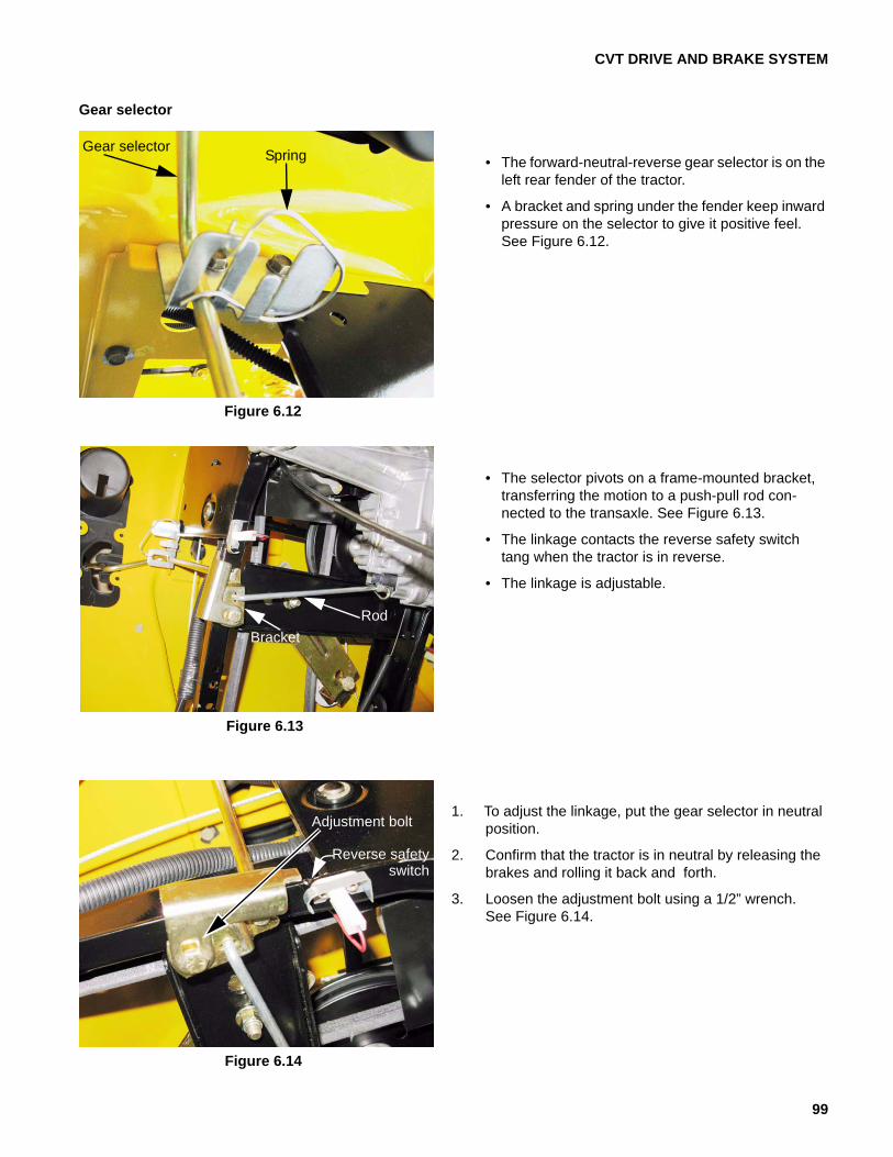
Gear selector
• The forward-neutral-reverse gear selector is on the left rear fender of the tractor.
• A bracket and spring under the fender keep inward pressure on the selector to give it positive feel. See Figure 6.12.
• The selector pivots on a frame-mounted bracket, transferring the motion to a push-pull rod con-nected to the transaxle. See Figure 6.13.
• The linkage contacts the reverse safety switch tang when the tractor is in reverse.
• The linkage is adjustable.
1. To adjust the linkage, put the gear selector in neutral position.
2. Confirm that the tractor is in neutral by releasing the brakes and rolling it back and forth.
3. Loosen the adjustment bolt using a 1/2” wrench. See Figure 6.14.
Figure 6.12
Gear selector Spring
Figure 6.13
RodBracket
Figure 6.14
Adjustment bolt
Reverse safety switch

LTX Tractors
100
4. Check that the gear selector handle is fully seated in the N notch on the fender. See Figure 6.15.
5. Tighten the adjustment bolt and re-check the posi-tion of the gear selector.
Tensioner pulley control rod
The tensioner pulley control rod is the link that ties the pedal shaft to the pulleys that tighten the front drive belt. See Figure 6.16.
If the tensioner pulley control rod is out of adjustment:
• Gear engagement may be crunchy (if the clutch/brake is not set) because the front drive belt tension is not fully released. Link too short.
• The tractor may creep when it is in gear, even though the operator’s foot is not on the drive control pedal. Link too short.
• The tractor may not have it’s full range of ground speeds. Link too long.
The tensioner pulley control rod may also need to be adjusted after the drive belts are replaced.
Figure 6.15
Figure 6.16
tensionerpulley control rod

CVT DRIVE AND BRAKE SYSTEM
101
To check and adjust the link:
1. Set the belts to their lowest speed position;
1a. Start the engine.
1b. Place the gear selector in Neutral and release the brake pedal.
1c. Depress the drive pedal to the end of its travel.
1d. Slowly release the drive pedal.
1e. When the drive pedal has reached the top of its travel, turn-off the engine.
2. Remove the mowing deck.
3. Loosen the link jam nut using a 9/16” wrench. See Figure 6.17.
4. Remove the nut that holds the link to the tensioner pulley bracket using a 9/16” wrench.
5. Remove and discard the cotter pin that holds the plain end of the rod to the cobra head arm on the pedal shaft. See Figure 6.18.
6. Pull both pedals (clutch/brake & drive control) all the way back. Secure them with a shock cord if neces-sary.
NOTE: The ball joint end of the rod will not come out of the tensioner pulley bracket, but pushing it up slightly makes it easier to adjust the rod length.
7. Thread the rod into or out of the ball joint end to lengthen or shorten it.
8. Adjust the rod so that the hole in the plain end fits over the arm on the pedal shaft.
9. Install the lock-washer and nut on the ball-joint stud, then re-check the adjustment.
10. Once the adjustment is correct, fasten the rod to the arm with a new cotter pin.
11. Tighten the jam nut.
12. Test-run the tractor to confirm that the drive and brake systems work correctly before reinstalling the mowing deck.
13. Test run the tractor again after the mowing deck is installed, and confirm that all of the safety features work properly.
Figure 6.17
Jam nut
Figure 6.18
Plain end
cobra head

LTX Tractors
102
Linkage: pedal shaft
Description: The Clutch/brake pedal and the drive control pedal operate on two concentric shafts.
• The clutch/brake shaft runs the full width of the tractor.
• The drive control shaft is tubular, and pivots on the clutch/brake shaft.
• Each shaft has a toothed latch plate. The latch plates are next to each other.
• The cruise control/park brake lever operates a common pawl that engages the latch plate of whichever pedal is applied. See Figure 6.19.
• A travel limit pin passes through curved slots in both of the latch plates. The pin is blocked into place by the fenders. See Figure 6.20.
Pedal shaft assembly removal:
NOTE: Confirm that the parking brake is released before starting work.
1. Remove the mowing deck.
2. Remove the fenders, as described in the body pan-els chapter of this manual.
3. Disconnect the rod that joins the arm at the left side of the brake/clutch shaft to the drive belt tensioner pulley bracket. See Figure 6.21.
• Remove and discard the cotter pin.
• The rod will come out easily as the pedal shaft assembly is lowered out of the tractor.
Figure 6.19
Cruise / park pawl
Clutch/brakelatch plate
Drive (cruise control) latch plate
Figure 6.20
Travel limit pin
Figure 6.21
Clutch/brake shaft Rod

CVT DRIVE AND BRAKE SYSTEM
103
4. Remove the locking clip that holds the travel limit pin in place.
5. Withdraw the travel limit pin. See Figure 6.22.
6. Unhook and remove the clutch/brake pedal return spring.
7. Remove the cotter pin and flat washer that hold the brake rod into the latch plate. Discard the cotter pin.
8. Remove and discard the cotter pin that holds the ten-sioner pulley control rod to the “cobra head” arm on the drive control pedal. See Figure 6.23.
9. Remove and discard the push cap that holds the drive control pedal shaft onto the clutch/brake shaft. See Figure 6.24.
Figure 6.22
Travel limit pin
Figure 6.23
Return spring
Flat washer
Brake rod
Cobra head
Control rod
Figure 6.24
Tie-rodseparator
Push cap

LTX Tractors
104
10. Loosen the bolt that holds the left pedal shaft sup-port strap using a 1/2” wrench. See Figure 6.25.
11. Remove the bolt that holds the right pedal shaft sup-port strap using a 1/2” wrench.
NOTE: This will allow the pedal shaft assembly to hang-down slightly on the right side of the tractor.
12. As the pedal shaft is lowered, and the drive control pedal shaft can be slipped to the right: See Figure 6.26.
• The brake rod will slip out of the latch plate on the brake pedal shaft.
• The rod that ties the arm at the left end of the brake pedal shaft to the tensioner pulley bracket will slip free.
13. Remove the bolt from the left side pedal shaft sup-port strap, and remove the pedal shaft assembly from the tractor. See Figure 6.27.
Figure 6.25
Left pedal shaft support strap
Figure 6.26
Figure 6.27
Brake pedal bracket Drive pedal bracket
Complete pedal shaft assembly
Arm for brake link to tension pulley bracket cruise latch plate
Cobra-head
Tie plate Brake latch plate

CVT DRIVE AND BRAKE SYSTEM
105
14. Disconnect the cobra-head rod from the pedal shaft tie plate. See Figure 6.28.
• Slip the tie plate off of the cobra head rod.
• Push the hex bushing out of the big end of the pedal shaft tie plate.
• The hex bushing can be snapped-off of the brake pedal shaft.
15. Once the cobra-head rod is loose, the drive control pedal shaft can be rotated and slipped off of the brake pedal shaft. See Figure 6.29.
16. Inspect the pedal shaft components individually. Replace any parts that are worn or damaged.
• The plastic bushings that fit between the two pedal shafts should be replaced any time they are removed. Lubricate them with a dry PTFE or graphite-based lubricant on assembly. NOT grease.
• Replace the push cap and all removed cotter pins with new parts.
17. Install the pedal shaft assembly by reversing the steps used to remove it, then install the fenders.
NOTE: The pedal shaft support straps are two different sizes. The smaller strap holds-up the left (brake pedal) end of the pedal shaft assembly. The larger strap holds-up the right (drive control pedal) end of the pedal shaft assembly. See Figure 6.30.
Figure 6.28
Cobra-head
Tie plate
Hex bushing
Figure 6.29
Drive control pedal shaft
Cobra head
Bushings
Brake pedalshaft
Figure 6.30
Left side strap Right side strap
LTX Tractors
106
17a. Lubricate the points where the pedal shafts meet the frame with a good quality lithium-based grease. See Figure 6.31.
17b. Position the two rods that connect to the brake pedal shaft as the pedal shaft assembly is being lifted into the tractor:
• The rod that de-tensions the drive belts when the brake pedal is pressed.
• The brake rod.
• The rods fit into the holes in the brake shaft much more easily before the pedal shaft is fully in position.
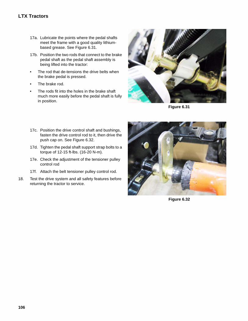
17c. Position the drive control shaft and bushings, fasten the drive control rod to it, then drive the push cap on. See Figure 6.32.
17d. Tighten the pedal shaft support strap bolts to a torque of 12-15 ft-lbs. (16-20 N-m).
17e. Check the adjustment of the tensioner pulley control rod
17f. Attach the belt tensioner pulley control rod.
18. Test the drive system and all safety features before returning the tractor to service.
Figure 6.31
Figure 6.32
CVT DRIVE AND BRAKE SYSTEM
107
Linkage: pedal tie strap
NOTE: If there is reason to remove the pedal tie strap, it can be taken off without further disassembly of the pedal shaft. The most likely reason for this would be the discovery of damage to the plate or hex bushing while making an adjustment to the ten-sioner pulley control rod.
1. Remove the mowing deck.
2. Remove and discard the cotter pin that holds the ten-sioner pulley control rod and the tie plate to the “cobra-head” arm on the drive control pedal shaft. See Figure 6.33.
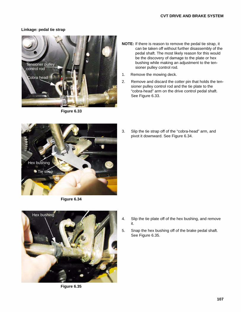
3. Slip the tie strap off of the “cobra-head” arm, and pivot it downward. See Figure 6.34.
4. Slip the tie plate off of the hex bushing, and remove it.
5. Snap the hex bushing off of the brake pedal shaft. See Figure 6.35.
Figure 6.33
Tensioner pulley control rod
Cobra head
Figure 6.34
Hex bushing
Tie strap
Figure 6.35
Hex bushing

LTX Tractors
108
NOTE: The hook on the tie strap goes over the trimmed section of the flange on the hex bushing. See Figure 6.36.
6. Install the tie strap by reversing the process used to remove it. Use a new cotter pin.
7. Test-drive the tractor to confirm that the drive sys-tem is working correctly before returning it to ser-vice.
Figure 6.36

CVT DRIVE AND BRAKE SYSTEM
109
Belt control: tension make-up pulley
1. Remove the upper drive belt from the make-up ten-sioner pulley as described in the drive belts section of this chapter. See Figure 6.37.
2. Unbolt the arm from the torque bracket using a pair of 9/16” wrenches. See Figure 6.38.
! CAUTION! CAUTION The battery will be removed in this procedure. Review the Operator’s Manual and Chapter 7: Electrical System for important safety information about handling batteries before proceeding.
Figure 6.37
Bolt loosened
Figure 6.38
Tension make-uparm pivot bolt

LTX Tractors
110
3. The arm pivots on a shouldered bushing. See Figure 6.39.
• A shoulder bolt threads into the bottom of the arm, for the tension spring to hook onto.
• The tension make-up pulley bolts to the top of the arm.
4. Install the arm by reversing the procedure used to remove it.
• Lubricate the pivot point with grease or anti-seize compound.
• One end of the tensioner spring is offset. The offset end connects to the arm.
Figure 6.39
Tension make-up pulley Shoulder bushing
Mounting bolt
Shoulder bolt
Figure 6.40

CVT DRIVE AND BRAKE SYSTEM
111
Belt control: variable speed pulley
1. Remove the battery and battery tray by following the procedures described in Chapter 4: Body Panels. See Figure 6.41.
2. Disconnect the lateral spring from the frame, relieving tension from the make-up pulley.
3. Roll the upper drive belt off of the transmission input pulley and the top sheave of the variable speed pul-ley.
4. Remove the input pulley from the transaxle using a 7/8” wrench. See Figure 6.42.
! CAUTION! CAUTION The battery will be removed in this procedure. Review the Operator’s Manual and Chapter 7: Electrical System for important safety information about handling batteries before proceeding.
Figure 6.41
Lateral spring
Figure 6.42
Input pulley

LTX Tractors
112
5. Roll the lower drive belt out of the lower sheave of the variable speed pulley. See Figure 6.43.
6. Unbolt variable speed pulley bracket from the tran-saxle using a 3/8” wrench.
7. Loosen, then remove the bolts that hold the variable speed pulley bracket to the frame using a 1/2” wrench. See Figure 6.44.
8. Lift the variable speed pulley and bracket out of the tractor.
9. Bench repairs:
9a. Clamp the pulley and bracket assembly into a vise, gripping the center shaft of the variable speed pulley.
9b. Use a 1/2” wrench to remove the pulley bolt. See Figure 6.45.
Figure 6.43
Variable speed pulley
Bracketbolts
Figure 6.44
Variable speed pulley bracket bolts
Figure 6.45
Bracket
Belt keeper
Variable speedpulley bolt

CVT DRIVE AND BRAKE SYSTEM
113
9c. Lift the bracket, belt keeper, and bearing holder off of the pulley.
9d. Clamp the variable speed pulley bracket into a vise. Match-mark the bracket to the belt keeper. See Figure 6.46.
9e. Remove the three screws that fasten the bear-ing holder to the bracket, and lift away the bear-ing holder. See Figure 6.47.
9f. Inspect the bearings and variable speed pulley.
• The bearings should turn smoothly, with no unusual noise.
• The variable speed pulley should spin true in the bearings.
• The center partition of the variable speed pulley should slide up-and-down smoothly.
9g. Reassemble the variable speed pulley by reversing the steps used to disassemble it.
10. Reinstall the variable speed pulley assembly in the tractor by reversing the steps used to remove it.
• Apply thread locking compound such as LocTiteTM 242 (blue) to the variable speed pulley bolt. Tighten the bolt to a torque of 150-180 in-lbs (17-20 N-m).
• Tighten the bearing holder screws to a torque of 90-135 in-lbs (10-15 N-m).
11. Run and test the drive system before returning the tractor to service.
Figure 6.46
Bearing holder Bearings
Figure 6.47
Bearing cover
Bracket
keeperBelt
Bearings

LTX Tractors
114
Belt control: tensioner pulleys
NOTE: The V-pulley can be removed from below using a 1/2” wrench, with no disassembly beyond removing the cutting deck. See Figure 6.48.
NOTE: Confirm that the parking brake is released before starting work.
1. Remove the mowing deck.
2. Remove the fenders, as described in the body pan-els chapter of this manual.
3. Disconnect the rod that joins the arm at the left side of the clutch/brake shaft to the drive belt tensioner pulley bracket. See Figure 6.49.
• Remove and discard the cotter pin to discon-nect the rod.
4. Disconnect the light extension spring that returns the bracket and pulley to the relaxed position when the drive pedal is released. See Figure 6.50.
Figure 6.48
V-pulley
Figure 6.49
Cotter pin Rod
Figure 6.50
Return spring

CVT DRIVE AND BRAKE SYSTEM
115
5. Remove the nut that holds the ball joint end of the tensioner pulley control rod to the tensioner pulley bracket using a 1/2” wrench. See Figure 6.51.
6. Note the belt routing, then slip the drive belt off of the two pulleys on the tensioning bracket.
7. Remove the nut and bolt that hold the belt tensioner pulley bracket to the frame using a pair of 9/16” wrenches. See Figure 6.52.
8. Maneuver the belt tensioner bracket assembly to clear the belt, and remove it from the tractor. See Figure 6.53.
NOTE: The bracket assembly pivots on the bolt that passes through the fixed flat-sheave idler pulley.
Figure 6.51
Figure 6.52
Figure 6.53
LTX Tractors
116
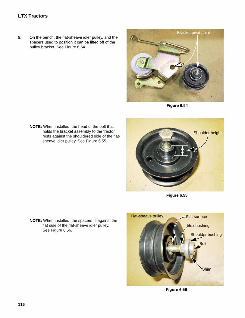
9. On the bench, the flat-sheave idler pulley, and the spacers used to position it can be lifted off of the pulley bracket. See Figure 6.54.
NOTE: When installed, the head of the bolt that holds the bracket assembly to the tractor rests against the shouldered side of the flat-sheave idler pulley. See Figure 6.55.
NOTE: When installed, the spacers fit against the flat side of the flat-sheave idler pulley. See Figure 6.56.
Figure 6.54
Bracket pivot point
Figure 6.55
Shoulder height
Figure 6.56
Flat surface
Hex bushing
Shoulder bushing
Bolt
Flat-sheave pulley
Shim

CVT DRIVE AND BRAKE SYSTEM
117
10. The V-sheave tensioner pulley can be un-bolted from the bracket using a 1/2” wrench.
11. The rod that connects the bracket to the clutch/brake pedal shaft can be maneuvered to come out of its slot in the bracket. See Figure 6.57.
12. Assemble and install the belt tensioner pulley by reversing the steps used to remove and disassemble it.
• Lubricate the pivot point with a good quality lith-ium-base grease.
13. Reinstall the fenders.
14. Test the drive system and all safety features before returning the tractor to service.Figure 6.57

LTX Tractors
118
Drive belt replacement
NOTE: The variable speed pulley system that drives this tractor counts on interplay between two belts:
• If one belt fails, replace both belts. One new belt and one partially worn belt will not work the same as two new belts.
• Do not use any belt other than the correct Cub Cadet part number belt. This drive system counts on an unusual cross-section shape of the belts. Use of a wrong belt will very likely cause the tractor not to drive properly.
• Check the tensioner pulley control rod adjust-ment after replacing belts.
1. Remove the mowing deck.
2. Set the park brake to release belt tension.
3. Remove the battery and battery tray by following the procedures described in Chapter 4: Body Panels. See Figure 6.58.
4. Remove upper (rear) drive belt:
4a. Release the lateral spring that provides force for the tension idler pulley. See Figure 6.59.
! CAUTION! CAUTION The battery will be removed in this procedure. Review the Operator’s Manual and Chapter 7: Electrical System for important safety information about handling batteries before proceeding.
Figure 6.58
Figure 6.59
Lateral spring

CVT DRIVE AND BRAKE SYSTEM
119
NOTE: Use a rope to unhook the spring from the frame. See Figure 6.60.
4b. Loosen the tension idler pulley from its bracket using a 1/2” wrench.
4c. Lift the pulley far enough to allow the belt to clear the belt keepers. See Figure 6.61.
4d. The slack created will allow the upper belt to slip easily out of the top sheave of the variable speed pulley and off of the transmission input pulley. See Figure 6.62.
4e. Withdraw the belt through the battery opening under the seat.
Figure 6.60
End of spring
Starter rope
Figure 6.61
Tension idler pulley
Rear drive belt
Figure 6.62
Variable speed pulley
Upper belt

LTX Tractors
120
5. Remove the lower (front) drive belt:
5a. Slip the belt off of the two tensioner pulleys. See Figure 6.63.
5b. Roll the belt off of the lower sheave of the vari-able speed pulley. See Figure 6.64.
NOTE: The belt can be walked-up from the lower sheave to the upper sheave, then off. Rotate the variable speed pulley to help slip the belt past the belt keepers.
5c. Remove the belt from the engine pulley.
Manual PTO
A. Loosen the crankshaft pulley using a 5/8” wrench.
NOTE: An impact wrench and socket will be most effective. Otherwise it may be necessary to block the ring-gear to prevent the crankshaft from turning .
B. Drop crankshaft pulley down far enough to let the belt clear the belt keepers that are built into the bottom of the frame. See Figure 6.65.
Figure 6.63
Figure 6.64
Lower belt
Variable speed pulley
Figure 6.65
Upper belt
Crankshaft pulley

CVT DRIVE AND BRAKE SYSTEM
121
C. Work the belt past the PTO pulley, and with-draw it from the front of the tractor. See Figure 6.66.
Electric PTO
A. Remove the belt keeper near the crankshaft using a 1/2” wrench.
• One bolt holds the belt keeper to the frame, to the left side of the engine.
• A nut holds the belt keeper to the right side frame channel.
NOTE: The electric PTO belt keeper incorporates an anti-rotation bracket for the PTO clutch.
B. Disconnect the PTO clutch electrical plug from the harness.
Figure 6.66
Figure 6.67
Nut
Belt keeper
Bolt
Figure 6.68
Wire harness
PTO clutch plug

LTX Tractors
122
C. Remove the bolt that holds the PTO clutch to the engine crankshaft using a 5/8” wrench. See Figure 6.69.
NOTE: An impact wrench and socket will be most effective. Otherwise it may be necessary to block the ring-gear to prevent the crankshaft from turning .
D. Carefully lower the PTO clutch and any asso-ciated hardware. See Figure 6.70.
E. Slide the pulley off of the engine crankshaft. The belt will clear the belt keepers as the pul-ley comes down. See Figure 6.71.
Figure 6.69
Crankshaft bolt PTO Clutch
! CAUTION! CAUTIONThe PTO clutch is heavy, and it may fall as the bolt is removed.
Figure 6.70
Washers (2)PTO clutch
Crankshaft bolt
Figure 6.71
Belt keepers

CVT DRIVE AND BRAKE SYSTEM
123
F. Withdraw the belt from the front of the tractor.
NOTE: The flat edge of the crankshaft pulley faces the electric PTO clutch. The end with the inside diame-ter chamfered goes against the fillet near the base of the crankshaft. See Figure 6.72.
NOTE: If the drive belt failed prematurely, identify and cor-rect the cause of the failure before installing a new belt.
6. Install the new belt by reversing the steps used to remove it.
Belt installation notes:
• Install only correct OEM belts. Incorrect belts may cause problems that effect the performance and/or safety of the tractor.
• Apply a small amount of anti-seize compound to the engine crankshaft before installing the crank-shaft pulley.
• Apply a small amount of thread locking compound such as Loctite 271TM (red) to the threads of the crankshaft bolt.
• Tighten the crankshaft bolt to a torque of 36-50 ft-lbs (50-68 N-m).
• The belt is routed to the left of the steering shaft, and the foremost keeper pin goes between the runs of the belt. See Figure 6.73.
7. Thoroughly test the operation of the drive system and all safety features before returning the tractor to ser-vice.
Figure 6.72
Top of crankshaft pulley
Bottom of crankshaft pulley
Figure 6.73
Belt routing

LTX Tractors
124
Transaxle removal and replacement
1. Remove the upper drive belt as described in the drive belt replacement section of this chapter.
2. Remove the input pulley and input pulley adaptor from the transaxle using a 7/8” wrench. See Figure 6.74.
NOTE: A crow foot wrench with a long extension works well for this step. Use a tapered pin to keep the pulley from rotating.
NOTE: The recessed side of the pulley faces up. See Figure 6.75.
! CAUTION! CAUTION The battery will be removed in this procedure. Review the Operator’s Manual and Chapter 7: Electrical System for important safety information about handling batteries before proceeding.
Figure 6.74
Input pulley
Figure 6.75
Top
Bottom

CVT DRIVE AND BRAKE SYSTEM
125
3. Loosen, but do not remove the wheel bolts (Double-D axles) or lug nuts, using a 1/2” wrench or a 3/4” wrench, respectively.
4. Unbolt the variable speed pulley bracket from the transaxle using a 3/8” wrench. See Figure 6.76.
5. Lift, and safely support the tractor. The rear of the tractor should be high enough to allow the transaxle to pass under it.
6. Remove the rear wheels. If the tractor has Double-D axles, remove the wheel spacers too. See Figure 6.77.
7. Disconnect the forward-neutral-reverse gear selector rod from the transaxle by removing the hair pin clip. See Figure 6.78.
Figure 6.76
bracket boltsV.S. pulley
Figure 6.77
Figure 6.78
f-n-r selector rod
Hair pin clip

LTX Tractors
126
8. Disconnect the forward-neutral-reverse gear selec-tor rod from the gear selector by rotating the rod 90 degrees. The coined ears on the rod will align with notches in the selector, and the rod can be pulled-free. See Figure 6.79.
9. Support the transaxle so that it can be lowered out of the tractor in a controlled fashion.
10. Remove the torque bracket bolts using a 1/2” wrench. See Figure 6.80.
11. Take the nuts off of the T-bolts that hold the tran-saxle to the frame using a 1/2” wrench. See Figure 6.81.
Figure 6.79
Figure 6.80
Torque bracket bolts
Figure 6.81
T-bolts

CVT DRIVE AND BRAKE SYSTEM
127
NOTE: At this point, the brake actuator spring is still attached to the brake rod from the pedal shaft, and the brake arm on the transaxle.
12. Carefully lower the transaxle out of the tractor. See Figure 6.82.
13. Move the transaxle forward to make some slack in the brake linkage. Use the slack to unhook the brake spring from the brake rod. See Figure 6.83.
Figure 6.82
Figure 6.83
Brake rod
Unhook here

LTX Tractors
128
NOTE: The brake spring has a tighter hook on the brake arm end than on the brake rod end. It is much easier to disconnect the spring from the rod. See Figure 6.84.
14. Carefully lift the transaxle onto a workbench for dis-assembly as needed.
15. Installation notes:
15a. Check adjustment of the brake before install-ing the transaxle.
15b. Connect both ends of the brake actuator spring before lifting the transaxle back into the tractor.
15c. Coat the Double-D axle shaft with a high qual-ity grease or anti seize compound before installing the wheels
15d. The wheel spacer sleeves are of different lengths: the short one goes on the right, the long one goes on the left.
15e. Install the transaxle by reversing the steps used to remove it.
15f. Tighten fasteners according to the torque table at the end of this chapter.
16. Operate and test the drive system, brake system, and all safety features before returning the tractor to service
Figure 6.84
Rod end
Arm end

CVT DRIVE AND BRAKE SYSTEM
129
Transaxle repair
1. Assess the damage from the outside: See Figure 6.85.
1a. If the tractor is within the warranty period, is the damage consistent with a warrantable failure?
1b. If the tractor is beyond the warranty period, is the transaxle feasible to repair?
1c. Are the axles bent?
1d. Is the housing broken from the outside-in?
1e. Is the housing broken from the inside-out?
1f. Spin-test:
• Will the input shaft turn in neutral?
• Will it drive the wheels forward in forward gear? Hold the brake rotor and check input-shaft back-lash. It should be 0.006”-0.014” (0.15-0.36mm).
• Will it drive the wheels backward in reverse gear? Hold the brake rotor and check input-shaft back-lash. It should be 0.006”-0.014” (0.15-0.36mm).
1g. If it fails the spin test, are the brakes too tight?
2. If further investigation is required to determine the cause of the failure or to asses the feasibility of repair, disassemble the transaxle using the following steps:
NOTE: steps #4 through #6 can be skipped if this is a war-ranty-related autopsy.
3. Slide the shift shaft pillow block off of the shift shaft. See Figure 6.86.
4. Remove the detent screw using a 1/4” allen wrench.
5. Use a magnet, or turn the transaxle upside-down to remove the detent ball and spring. See Figure 6.87.
Figure 6.85
Figure 6.86
Shift shaft
Pillow block
Figure 6.87
Detent ball
Detent spring
Detent screw
Detent screw hole

LTX Tractors
130
6. Disassemble the brake:
6a. Unhook and remove the brake spring. See Figure 6.88.
6b. Unbolt the brake yoke from the transaxle using a 3/8” wrench. See Figure 6.89.
6c. Slip the brake rotor off of the brake shaft (splined end of bevel gear shaft). See Figure 6.90.
Figure 6.88
Figure 6.89
Brake yoke
Figure 6.90
Brake rotor
Brake pad (fixed)
Brake shaft

CVT DRIVE AND BRAKE SYSTEM
131
6d. Inspect the brake shaft and inner brake pad.
NOTE: The inner pad is epoxied in-place, but may be pried-out for replacement.
6e. Disassemble and inspect the brake yoke. See Figure 6.91.
7. Remove the 13 remaining perimeter screws that hold the upper transaxle housing to the lower transaxle housing using a 3/8” wrench.
8. Separate the two housings. See Figure 6.92.
NOTE: The axle shafts will generally be of different lengths. Mark, or note the orientation of the differ-ential and axle assembly to the transaxle housing before removing it.
9. Lift the axle and differential housing out of the tran-saxle. See Figure 6.93.
10. Note the positions of the shim washers.
Figure 6.91
Brake arm
Brake yoke
Brake pins
Backing plate
Brake pad
Figure 6.92
Lower housing
Upper housing
Figure 6.93
Shims

LTX Tractors
132
11. Slip the seals, bearings, and washers off of the dif-ferential and axle assembly. See Figure 6.94.
NOTE: When correctly installed, the seals fit on the axle shaft with the lips facing out. Their pri-mary purpose is to exclude dirt and mois-ture. Grease does not tend to migrate past the axle seals.
NOTE: If the transaxle is to be re-built, replace the bearings and seals with new ones.
12. Inspect the differential and axle assembly.
12a. Look for damaged ring gear teeth.
12b. With the ring gear held still, turning one axle should cause the other axle to rotate smoothly in the opposite direction.
12c. Look for rust or excessive wear on the bearing contact surfaces.
12d. Problems in any of these areas mean the differential assembly should be replaced.
12e. If this is a warranty-related autopsy, identify the root cause of the problem. If it is not something that was done wrong at the factory, the problem is not warrantable.
NOTE: Cub Cadet does not have a part number for water, and it is not installed at the factory.
13. Lift the bevel gears out of the transaxle for disas-sembly and (mostly) visual inspection. See Figure 6.95.
13a. Note the placement of the shims on the bevel gear shaft.
13b. Check the bevel gear teeth (that mesh with the pinion gear) for wear or damage.
13c. Check the shift collar engagement teeth on the bevel gears for wear or damage.
13d. Check the inside bearing surface of each bevel gear for wear or damage.
13e. Check the bevel gear shaft for wear or dam-age.
Figure 6.94
Differential and axle assembly
Figure 6.95
Forward bevel gear Reverse bevel gear
Engagement teeth
Shift collar

CVT DRIVE AND BRAKE SYSTEM
133
13f. Check the shift collar and fork for wear.
13g. Check shift collar teeth and splines for wear or damage. See Figure 6.96.
14. Check the interior of the transaxle housings.
14a. If there is heavy gear-tooth damage on the ring gear of bevel gears, there is likely to be large debris in the grease. Dispose of the grease if the transaxle is to be rebuilt.
14b. If there is heavy wear on any of the contact sur-faces, there is likely to be small particles of metal in the grease. Dispose of the grease if the transaxle is to be rebuilt.
14c. If the grease is obviously contaminated with water or other substances, dispose of the grease if the transaxle is to be rebuilt.
14d. If the transaxle is being warranted, leave the grease and debris in place, after the root cause of the failure is identified.
14e. If the transaxle is repaired, the damage is iso-lated, and the grease is not contaminated with anything, it is acceptable to re-use the grease. See Figure 6.97.
15. Inspect the pinion gear and input shaft assembly. See Figure 6.98.
15a. The pinion gear teeth should not show signs of heavy wear or damage.
15b. The input shaft should have 0.015”-0.020” (0.38-0.51mm) end-play, and 0.002”-0.010” run-out.
Figure 6.96
splines
Shift fork
Teeth
Figure 6.97
Figure 6.98
Feeler gauges

LTX Tractors
134
16. If there is a reason to take-apart the input pinion, use the following steps:
16a. Remove the hog-ring pulley stop by prying-open the end gap and slipping it up the shaft. See Figure 6.99.
16b. Use a screwdriver to pry-off the E-ring. See Figure 6.100.
16c. Remove the shim washers. See Figure 6.101.
Figure 6.99
Hog ring
Figure 6.100
Input shaft
E-ring
Figure 6.101
Shims set end-play

CVT DRIVE AND BRAKE SYSTEM
135
16d. Pull the pinion shaft out of the housing. See Figure 6.102.
16e. Inspect the shaft and bearings. See Figure 6.103.
Figure 6.102
Needle bearings
Figure 6.103
Pinion gear Thrust washer

LTX Tractors
136
17. Final evaluation:
It may not be necessary to fully disassemble the transaxle to identify the damage or find the root cause of a war-rantable failure.
At this point of disassembly, or some point earlier in the process, the technician should be able to make an assessment of whether it is feasible to repair the transaxle. It should also be possible to positively identify what went wrong in a warrantable transaxle replacement.
If the transaxle is to be warranted, reassemble it for shipping. It may be called back for inspection.
If repair is feasible, proceed by the following steps:
18. Assemble the pinion gear:
18a. Press-in new bearings, if necessary.
18b. Apply some Durina grease to the shaft and the contact surfaces between the base of the pinion gear and the thrust washer.
18c. Insert the shaft and washer from the inside of the housing.
18d. Install the shim washers and E-clip previously removed, then check end-play and run-out.
• Add shims to reduce end-play.
• Take-out shims to increase end-play.
19. Assemble and install the bevel gear shaft:
19a. Apply a small amount of anti-seize compound to the splined section of the shaft.
19b. Slide the reverse gear, shift collar, and for-ward gear onto the bevel gear shaft. See Figure 6.104.
NOTE: The gears are identical. Forward and reverse are functional references. The reverse bevel gear is nearest the reduction gear, while the forward gear is nearest the brake rotor spline.
Figure 6.104
Reduction gearBrake spline

CVT DRIVE AND BRAKE SYSTEM
137
19c. Re-install the shims in their original locations on the bevel gear shaft.
19d. Smear some DurinaTM grease on the surfaces of the shaft that will ride in the flange bearings.
19e. Install new bevel gear shaft bearings, with their flanges facing the shims. See Figure 6.105.
NOTE: The bevel gear shaft bearings are of different lengths.
The longer bearing goes on the reduction gear end of the shaft. The shorter bearing goes on the brake-spline end of the shaft.
19f. Install the brake shaft seal. The primary pur-pose of this seal is to keep grease away from the brakes. The seal should be installed with the lip facing in.
19g. Install the bevel gear shaft into the transmission housing for a dry fit check.
20. Install the axle and differential assembly:
20a. Check notes, markings, or witness marks on the axle shafts to confirm the correct orienta-tion. See Figure 6.106.
20b. Reinstall the end-play shims in their original positions.
20c. Apply a small amount of DurinaTM grease to the inboard bearing contact surfaces of the axle, then slide new bearings into place.
20d. Apply a small amount of DurinaTM grease to the outer bearing contact surfaces of the axle, then slide new bearings into place.
20e. Slip the seals onto the axle shaft. The seal lip should face outward.
20f. Carefully place the assembly into the housing for a dry fit. See Figure 6.107.
Figure 6.105
Seal
Brake-side bearing(short)
Reduction-gearside bearing (long)
Shims
Shims
Figure 6.106
Witness marks
This axle is in backwards!
INCORRECT
NOTE: Witness marks not aligned w/case
Figure 6.107

LTX Tractors
138
21. Press the differential and the reverse gears as close together as they will go while remaining properly seated in the housing.
22. Confirm that there is at least 0.030” (0.762mm) between the rivet heads on the differential and the back side of the reverse gear. See Figure 6.108.
23. Collective axle end play (the amount one axle shaft moves when the opposite axle is pushed) should be between 0.010”-0.080” (0.25-2.0mm).
24. Adjust the shims as necessary to achieve these two conditions.
25. Install the shift fork.26. Install the top of the transaxle housing, and tighten
the perimeter screws finger-tight.27. Spin-test the transaxle in forward, neutral, and
reverse.28. Check the input shaft backlash:
28a. Engage forward gear, hold the brake spline and rotate the input shaft. The top edge of the input shaft should rotate between 0.006”-0.014” (0.15-0.36mm).
28b. Engage reverse gear, hold the brake spline and rotate the input shaft. The top edge of the input shaft should rotate between 0.006”-0.014” (0.15-0.36mm).
29. Remove the top of the housing, and adjust the bevel shaft gear shims as necessary, then re-check.NOTE: The backlash in the input shaft is a function of the amount of play between the pinion gear and the
bevel gear it is driving. Shimming a bevel gear to run nearer the pinion shaft will reduce the backlash. Removing shims to allow more space between the pinon and bevel gears will increase the amount of backlash.
30. Install, or add DurinaTM grease to a total of 20 fl.oz. (0.59 liters) in the housing.31. Carefully install the top of the housing, and install the 13 perimeter screws, leaving 2 empty screw holes; 1 on
each side of the brake spline.NOTE: No sealant is necessary.
32. Tighten the screws to a torque of 90-135 in-lbs. (10-15 N-m).
33. Install the detent ball, spring, and screw.34. Tighten the detent screw to a torque of 160-200 in-
lbs. (18-23 N-m).35. Assemble the brake yoke:
35a. Apply a small amount of anti-seize compound to the brake rotor splines and to the actuator pins in the brake yoke.
35b. Install the steel backing plate against the pins, then place the friction pad against the backing plate. See Figure 6.109.
Figure 6.108
Figure 6.109
! CAUTION! CAUTIONDo not get anti-seize on the fric-tion surfaces of the brake.

CVT DRIVE AND BRAKE SYSTEM
139
35c. Install the brake rotor, with the flat side facing the transaxle housing. See Figure 6.110.
35d. Install the brake yoke to the transaxle, being careful not to let the friction pad or backing plate fall out of place.
35e. Tighten the brake yoke screws to a torque of 90-135 in-lbs. (10-15 N-m).
35f. Set the clearance between the pads and rotor to 0.010-0.015” (0.25-0.38mm) using the adjusting nut on the brake yoke. See Figure 6.111.
35g. Re-hook the brake spring to the brake arm
35h. Re-install the shift rod pillow block.
35i. Give the transaxle a final spin-test before instal-lation.
Figure 6.110
Brake rotor
Figure 6.111
Adjustment nut

LTX Tractors
140
Transmission Specifcations
Specification U.S. Metric
Pinion end play 0.010”-0.015” 0.25-0.38mm
Pinion run-out 0.002”-0.010” 0.05-0.25mm
Pinion backlash 0.006”-0.014” 0.15-0.36mm
Differential rivet.-to-gear clearance 0.030” minimum 0.762mm
Axle end-play 0.010”-0.08” 0.25-2.0
Amount of Durina grease, 2 10 oz. tubes (P/N: 737-0148)
20 fl.oz 0.59 liters
Brake clearance 0.010”-0.015” 0.25-0.38mm
Drive System Torque Specs.
Fastener Torque in-lb. Torque N-m
Seat bolt 60-80 17-20
Lug nut 350-500 41-57
Wheel bolt 160-190 18-22
Crankshaft bolt 450-600 51-68
Tq. bracket bolt 175-250 20-28
Axle T-bolt nuts 150-180 17-20
Tensioner bracket 150-180 17-20
Pedal shaft straps 150-180 17-20
Belt keeper nut /bolt 150-180 17-20
Idler pulley bolt 150-180 17-20
Brake yoke bolts 90-135 10-15
Input pulley nut 300-400 34-45
Housing screws 90-135 10-15
Detent screw 160-200 18-23
V.S. pulley bolt 150-180 17-20
V.S. bearing cover 90-135 10-15
Make-up pulley pivot bolt 175-250 20-28