chapter 5: timers and counters - personal.kent.edupersonal.kent.edu/~asamba/tech43550/chap05.pdf ·...
TRANSCRIPT

Chapter 5: Timers and Counters
Computer Aided Manufacturing TECH 4/53350 1
Ladder LogicLearning objectivesLearning objectives
Describe the use of timers and counters in ladder logic
Describe such terms as retentive cascade delay on Describe such terms as retentive, cascade, delay onand delay off
E l i th ti f TON TOF d RTO ti Explain the operation of TON, TOF, and RTO timers
Explain the use of CTU and CTD timersp
Utilize timers and counters in ladder logic
Computer Aided Manufacturing TECH 4/53350 2

TimersOverview
Ti d t d l ti
Overview
Timers are used to delay actions Keep an output on for a specified time after an input turns off Keep an output off for a specified time before it turns on
Timing functions are vital in PLC applications Cycle times are critical in many processes
Many PLCs use block-type timers and counters Compliance with IEC 61131-3 standards
Computer Aided Manufacturing TECH 4/53350 3

Block-Type TimerE lExample
TON
TIMER ON DELAYTimer T4:0Time Base 0.1Preset 50Accum 0
TONEN
DN
I:2
Ti A ib
Above Timer is labeled T4:0
Time Base: Timers are typically programmed with several different time bases
Timer Attributes
yp y p g 1 second, 0.1 second, 0.01 second, 0.001 second Suppose time base is set to 0.1 and Delay increments is set to 50
timer has 5 seconds delay (0.1 x 50)
Computer Aided Manufacturing TECH 4/53350 4

Block-Type TimerExample
TON
Example
TIMER ON DELAYTimer T4:0Time Base 0.1Preset 50Accum 0
TONEN
DN
I:2
Preset Attribute: Preset value is the number of time increments timer must count
before changing the state of the output Time Delay = Preset value x Time Base ( refer to previous example) Preset can be constant or a variable
Computer Aided Manufacturing TECH 4/53350 5

Block-Type TimerExample
TIMER ON DELAY
TONENI:2
Example
Timer T4:0Time Base 0.1Preset 50Accum 0
DN
Accum Attribute: [Rockwell] Timers have one input. When the input transits from low
to high, the timer will begin timing (Accum value) Timers that do not lose their accumulated time when the enable input line
transitions to low again are known as Retentive Timers Retentive Timers continue to maintain accumulated time and increment
the time when the input line goes to high again Non-retentive Timers lose the accumulated time whenever the enable
input transitions to low The accumulated time resets to zero
Computer Aided Manufacturing TECH 4/53350 6
The accumulated time resets to zero

Timer BlockNumbering SystemNumbering System
TIMER ON DELAY
TONENI:2 TIMER ON DELAY
Timer T4:0Time Base 0.1Preset 50Accum 0
DN
I:2
T Fil T (Ti )
Above Timer is calledT4:0
Timer T4:0T File Type (Timer)4 File Number of the Timer: Delimiter0 Element (The actual timer number)0 Element (The actual timer number)
Computer Aided Manufacturing TECH 4/53350 7
Block-Type TimerE lExample
TONTIMER ON DELAYTimer T4:0Time Base 0.1Preset 50Accum 0
TONEN
DN
I:2
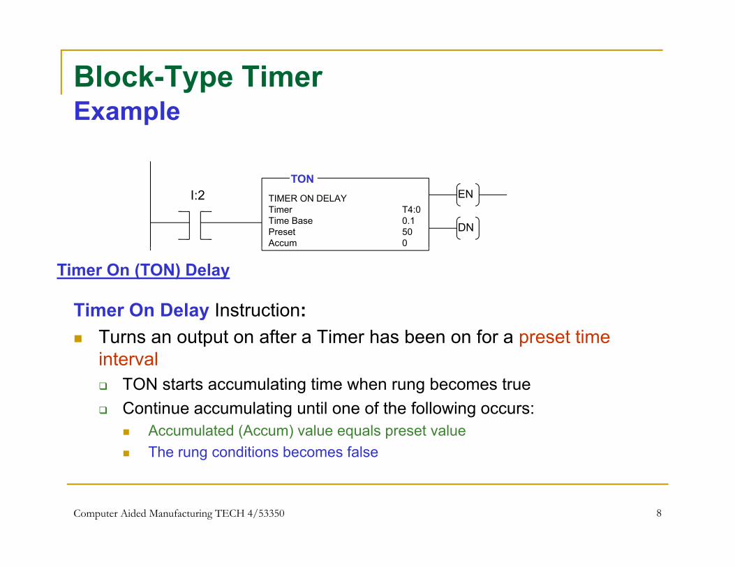
Timer On Delay Instruction:
Timer On (TON) Delay
y Turns an output on after a Timer has been on for a preset time
interval TON starts accumulating time when rung becomes true g g Continue accumulating until one of the following occurs:
Accumulated (Accum) value equals preset value The rung conditions becomes false
Computer Aided Manufacturing TECH 4/53350 8

Block-Type TimerStatus Bits (EN, DN, TT)Status Bits (EN, DN, TT)
Bit S t Wh R i S t Till
Timer Status bits can be used in ladder logic
Bit Set When Remains Set TillTimer done Bit(bit 13 or DN)
Accumulated value is equal to or greater than the
preset value
Rung conditions go false
Timer Timing bit(bit 14 or TT)
Rung conditions are true and the accumulated value
is less than the preset value
Rung conditions go false or when the done bit is set
Timer enable bit(bit 15 or EN)
Rung conditions are true Rung conditions go false
Computer Aided Manufacturing TECH 4/53350 9

Using Status Bits in Ladder LogicEN BitEN Bit
Timer Enabled bit can be used in ladder logicTimer Enabled bit can be used in ladder logic
Consider timer T4:0 from the example:
The Timer Enable (EN) bit is set immediately when the rung goes true. It stays set until the rung goes false
The EN bit indicates that the timer T4:0 is enabled
The EN bit from any timer can be used for logic:
T4:0/EN could be used as a contact in a ladder
Computer Aided Manufacturing TECH 4/53350 10

Using Status Bits in Ladder LogicTT BitTT Bit
Timer Timing (TT) bit can be sed in ladderTimer Timing (TT) bit can be used in ladder logicC id ti T4 0 f th l Consider timer T4:0 from the example:
The Timer Timing (TT) bit is set when the rung goes true. It stays set until the rung goes false or the Timer Done (DN) bit is set (i eset until the rung goes false or the Timer Done (DN) bit is set (i.e., when accumulated value equals preset value)
The TT bit from any timer can be used for logic:The TT bit from any timer can be used for logic:
T4:0/TT could be used as a contact in a ladder
Computer Aided Manufacturing TECH 4/53350 11

Using Status Bits in Ladder LogicDN BitDN Bit
Timer Done bit can be sed in ladder logicTimer Done bit can be used in ladder logic Consider timer T4:0 from the example:
The Timer Done (DN) bit is not set until the accumulated value is equal to the preset value. It stays set until the rung goes false
When DN bit is set, it indicates Timing operation is complete
The DN bit from any timer can be used for logic:
T4:0/DN could be used as a contact in a ladder
Computer Aided Manufacturing TECH 4/53350 12
Using Other Bits in Ladder Logic
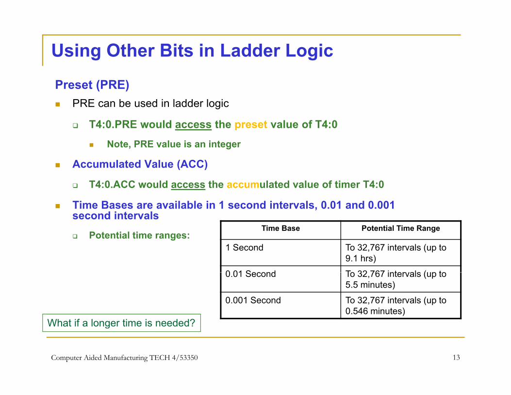
Preset (PRE) PRE can be used in ladder logic
T4:0 PRE would access the preset value of T4:0 T4:0.PRE would access the preset value of T4:0
Note, PRE value is an integer
Accumulated Value (ACC)
T4:0.ACC would access the accumulated value of timer T4:0
Time Bases are available in 1 second intervals, 0.01 and 0.001 second intervals
Potential time ranges:Time Base Potential Time Range
1 Second To 32,767 intervals (up to 9.1 hrs)
0 01 Second To 32 767 intervals (up to0.01 Second To 32,767 intervals (up to 5.5 minutes)
0.001 Second To 32,767 intervals (up to 0.546 minutes)
What if a longer time is needed?
Computer Aided Manufacturing TECH 4/53350 13
What if a longer time is needed?

Memory StorageTimers
15 14 13 12 11 10 9 8 7 6 5 4 3 2 1 0 BitsEN TT DN Internal Use
Preset Value
Accumulated Value
0 T4:0
1 T4:0.PRE
2 T4:0 ACC
Bits
Accumulated Value 2 T4:0.ACC
Current status of timer bits (EN, TT and DN) stored in first 16 bits PRE value is held in the second 16 bit of timer storage Third 16 bit holds accumulated value of timer
Computer Aided Manufacturing TECH 4/53350 14

TON Timer Ladder Diagram TONLadder Diagram
TIMER OFF DELAYTimer T4:0Time Base 1.0Preset 180Accum 0
TONEN
DN
I:2
3
T4:0O:5
TT 1
T4:0O:5
DN 2
When input I:2/3 is true timer begins to increment the accumulated value of TON Timer T4:0 in 1 second intervals
The TT bit is used in rung 2 to turn on Output O:5/1, while the timer is timing (ACC <PRE)The DN bit of timer 4:0 is used in rung 3 to turn an output O:5/2 when the timer is done The DN bit of timer 4:0 is used in rung 3 to turn an output O:5/2 when the timer is done timing (ACC = PRE)
Note: the Preset for this timer is 180 The timer will have to accumulate 180 1-second intervals to time out
Note: This is a non-retentive timer: If Input I:2/3 goes low before 180 is reached, the accumulated value
Computer Aided Manufacturing TECH 4/53350 15
is reset to zero

Timer OFF DelayTOFTOFTimer OF (TOF) -Delay Used to turn an output On or OFF after rung has Used to turn an output On or OFF after rung has
been off for a desired time1. TOF starts to accumulate time when the rung becomes false
2. It continues to accumulate time until the accumulated value equals the preset value or the rung becomes true
3. The timer enable bit (EN bit 15) is set when the rung becomes true. It is reset when the rung becomes false and ACC < PRE or the DN bit is reset (ACC = PRE)the DN bit is reset (ACC PRE)
4. The done bit (DN bit 13) is reset when the ACC value is equal to the PRE value. The DN bit is set when the rung becomes true
Computer Aided Manufacturing TECH 4/53350 16
g

Timer Off DelayTOF Bits
Bit S t Wh R i S t Till
TOF Bits
Bit Set When Remains Set Till
Timer done Bit(bit 13 or DN)
Rung conditions are true Rung conditions go false and the accumulated value is greater than or equal tois greater than or equal to
the preset value
Timer Timing bit(bit 14 or TT)
Rung conditions are false and the accumulated value
is less than the preset
Rung conditions go true or when the done bit is reset
is less than the preset value
Timer enable bit(bit 15 or EN)
Rung conditions are true Rung conditions go false
Computer Aided Manufacturing TECH 4/53350 17
Ladder LogicTOF Timer TOFTOF Timer
TIMER OFF DELAYTimer T4:0Time Base 1.0Preset 180Acc 0
TOFEN
DN
I:2
3
T4:0O:5
TT 1
This output is energized while the timer is timing
T4:0O:5
DN 2
This output is energized when the timer is done timing
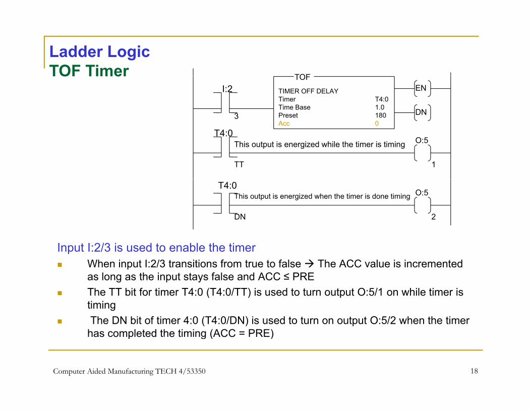
Input I:2/3 is used to enable the timer When input I:2/3 transitions from true to false The ACC value is incremented
as long as the input stays false and ACC ≤ PRE The TT bit for timer T4:0 (T4:0/TT) is used to turn output O:5/1 on while timer is
timing The DN bit of timer 4:0 (T4:0/DN) is used to turn on output O:5/2 when the timer
has completed the timing (ACC = PRE)
Computer Aided Manufacturing TECH 4/53350 18
has completed the timing (ACC = PRE)
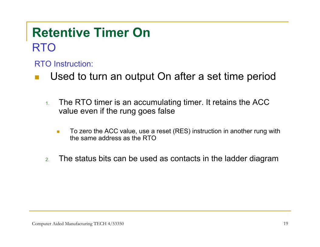
Retentive Timer OnRTORTORTO Instruction: Used to turn an output On after a set time period Used to turn an output On after a set time period
1. The RTO timer is an accumulating timer. It retains the ACC l if th f lvalue even if the rung goes false
To zero the ACC value, use a reset (RES) instruction in another rung with the same address as the RTOthe same address as the RTO
2. The status bits can be used as contacts in the ladder diagram
Computer Aided Manufacturing TECH 4/53350 19

Retentive Timer OnStatus Bits
Bit Set When Remains Set Till
Timer done Bit Accumulated value The appropriate RES
Status Bits
Timer done Bit(bit 13 or DN)
Accumulated value ≥ preset value
The appropriate RES Instruction is enabled
Timer Timing bit(bit 14 or TT)
Rung conditions are true and the accumulated value
< preset value
Rung conditions go false or when the done bit is set
< preset value
Timer enable bit(bit 15 or EN)
Rung conditions are true Rung conditions go false
Computer Aided Manufacturing TECH 4/53350 20

Ladder LogicRTO TimerRTO Timer
TIMER OFF DELAYTimer T4:0Time Base 1 0
RTOENI0:2
Time Base 1.0Preset 180Accum 0
DN
I0:2 T4:0
3
4
RES
EN bit is set when rung becomes true When EN is 1 Indicates Timer is timing
Note: EN remains 1until rung becomes false TT bit is set when rung becomes true and remains set until ACC value equalsTT bit is set when rung becomes true and remains set until ACC value equals
the preset value or RES instruction resets the timer DN bit is set when the timer’s ACC value is equal to the preset value
When DN bit is set it indicates timing is complete
Computer Aided Manufacturing TECH 4/53350 21

Cascading Timers
When Application requires longer time delays When Application requires longer time delays than a single timer can provide Use multiple timers Use multiple timers
When the first timer times out, it becomes an input to start the second timer timing

Cascading TimersTON
TIMER ON DELAYTimer T4:0Time Base 1.0Preset 32,767Accum 0
OEN
DN
I:2.0
1
TIMER ON DELAYTimer T4:1Time Base 1.0Preset 7233
TONEN
DN
T4:0
DN
Two timers are used to extend the time delay The first timer output, T4:0/DN, acts as input to second timer
Preset 7233Accum 0
DN
When Input I:2.0 becomes true, timer 1 begins to count to 32,767 seconds (the limit of the timers) When it gets to 32,767 seconds, output T4:0/DN turns on This energizes timer T4:1 Timer T4:1 times to 7233 seconds (its preset value)
T4:1/DN turns on
23
What is the delay?
Counters
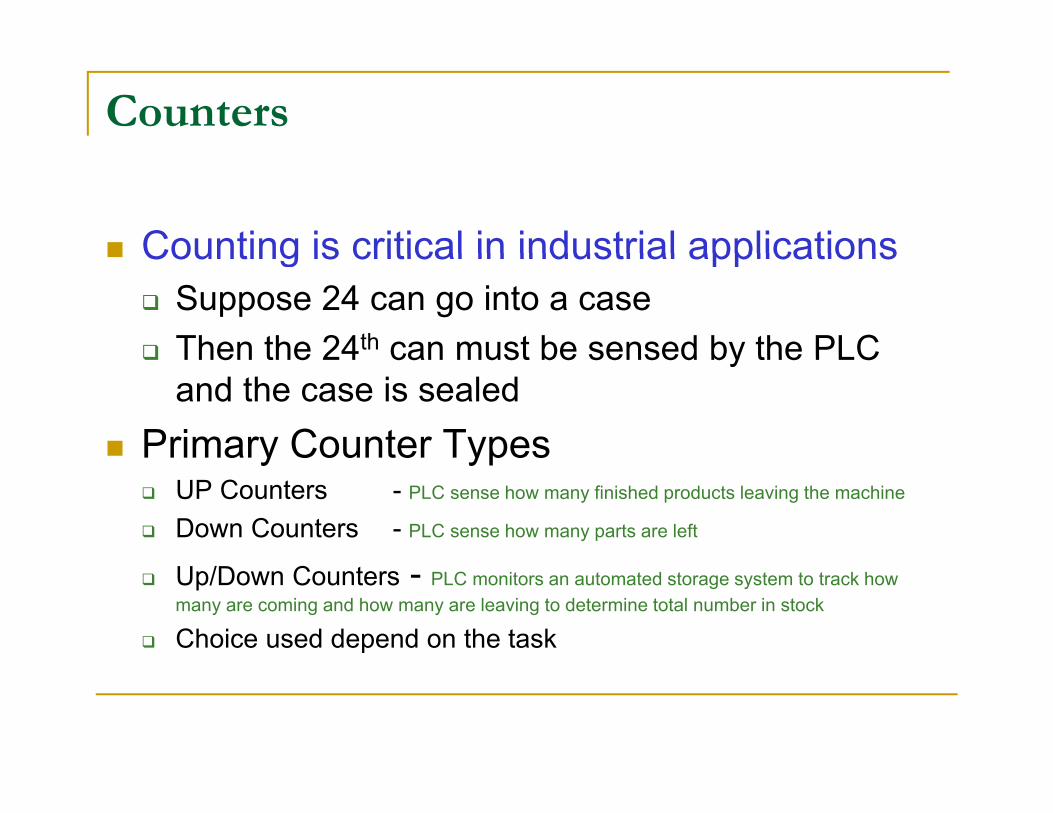
Counting is critical in industrial applications Counting is critical in industrial applications Suppose 24 can go into a case Then the 24th can must be sensed by the PLC Then the 24 can must be sensed by the PLC
and the case is sealed Primary Counter Typesy C yp
UP Counters - PLC sense how many finished products leaving the machine
Down Counters - PLC sense how many parts are left
Up/Down Counters - PLC monitors an automated storage system to track how many are coming and how many are leaving to determine total number in stock
Choice used depend on the task

CountersA ibAttributes
Counters usually use low-to-high transition from Counters usually use low to high transition from an input to trigger the counting action
Counters count the number of low-to-high gtransitions on the input line Similar to Timers, which count the number of time
increments Counters also have a reset instruction to clear
th l t d tthe accumulated count

Counters (CTU)Edge-Triggered Count Up
CTUENI:2Edge Triggered
Counter C5:0Preset 10Accum 0 DN
C5:0O:5
3
Energized when the Accum >= Preset
DN 1
Energized when the Accum >= Preset
Input I:2/3Status
Output O:5/1
OnOf
OnOf
The rising edge triggers the counter I:2/3 counts the pulses:
Status Of
1 2 10 110
I:2/3 counts the pulses: Each time there is an Of to On transition, the Counter increments its count by 1 (CTU) When the Accumulate count equals the preset value, the counter turns on
Turns on Output O:5/1How does CTD work?
Computer Aided Manufacturing TECH 4/53350 26
How does CTD work?

CountersNumbering SystemNumbering System
How counters are addressed:
C5:0C File Type5 File Number of the counter: Delimiter0 Element (The actual counter number)
Computer Aided Manufacturing TECH 4/53350 27

Counters in Ladder LogicAccessing Counter ValuesAccessing Counter Values
C5 4 DNTo use the Done Bit: C5:4.DN
To use the Preset Value C5:4.PRE
To use the Accumulated Value C5:4.ACC
Computer Aided Manufacturing TECH 4/53350 28

Memory StorageCTU Counter Bits
15 14 13 12 11 10 9 8 7 6 5 4 3 2 1 0Bits Element
CU DN OV Internal UsePreset Value
Accumulated Value
0 C5:0
1 C5:0.PRE
2 C5:0 ACC
Bits
Count Up (CU), Done (DN) and Overflow (OV) bits are stored in first 16 bits
Accumulated Value 2 C5:0.ACC
p ( ), ( ) ( ) The CPU sets the OV bit when the counter exceeds upper limit +32,767
ACC wraps around to -32,767 and continues from there towards zero PRE value is held in the second 16 bit of counter storage
Thi d 16 bit h ld l t d l f t Third 16 bit holds accumulated value of counter
Computer Aided Manufacturing TECH 4/53350 29

CTU Counter Bits
Bit S t Wh R i S t TillBit Set When Remains Set Till
Count-up Overflow bit(bit 12 or OV)
Accumulated value wraps around to -32,768 (from +32 767) and continues up
A RES instruction that has same address as the CTU instruction is executed or+32,767) and continues up
from there towards zeroinstruction is executed or the count is decremented less than or equal to +32,767 with a CTD instruction
Done bit(bit 13 or DN)
The accumulated value is => the preset value
The accumulated value becomes less than the preset value
Count-up enable bit (bit 15 Rung conditions are true Rung conditions go false orCount up enable bit (bit 15 or CU)
Rung conditions are true Rung conditions go false or a RES instruction that has the same address as the
CTU instruction is enabled

Count-Up CounterLadder Diagram COUNT UP
CTUENI:2Ladder Diagram
Counter C5:0Preset 4Accum 0 DN
C5:0O:5
3
Energized when the Accumulated ≥ Preset
DN 1
C5:0O:5
g
Energized when the counter overflows
OV 2
Input I:2/3 is used to enable the counter
g
Input I:2/3 is used to enable the counter Each time I:2/3 makes a low-to-high transition, the counter ACC value gets
incremented by1 The DN bit is set when the ACC value ≥ the Preset value
The DN bit of C5:0 (C5:0/DN) is used to turn on O:5/1 when ACC ≥ Preset value The OV bit of C5:0 (C5:0/OV) is used to set O:5/2 when <What happens?>
See next slide
Computer Aided Manufacturing TECH 4/53350 31

Count-Up CounterLadder Diagram COUNT UP
CTUENI:2Ladder Diagram
Counter C5:0Preset 4Accum 0 DN
C5:0O:5
3
Energized when the Accumulated >= Preset
DN 1
C5:0O:5
g
Energized when the counter overflows
OV 2
g
I:2 C5:0Reset counter to zero
The OV bit of C5:0 (C5:0/OV) is used to set O:5/2
1
RESese cou e o e o
if the count reaches +32,767 Bit 1 of contact I:2/1 is set to true(1) this causes the RES instruction to reset CTU C5:0’s ACC value (i.e
“Accum”) to zero
Computer Aided Manufacturing TECH 4/53350 32

Count-Down CounterLadder Diagram COUNT DOWN
CTDCDI:2Ladder Diagram
Counter C5:0Preset 4Accum 0 DN
C5:0O:3
3
Energized when the Accumulated ≥ Preset
DN 1
C5:0O:3
g
Energized when the counter underflows
UN 2
g
I:2 C5:0Resets counter to zero
1
RESese s cou e o e o
Input I:2/3 is used to enable the counter Each time input I:2/3 makes a 01 transition, the counter ACC value gets decremented by1
The DN bit is set when the ACC value ≥ the Preset value The DN bit of C5:0 (C5:0/DN) is used to turn output O:3/1 on when Accum ≥ Preset value The UN bit of C5:0 (C5:0/UN) is used to set OUTPUT O:3/2 ON when the ACC value
underflows (-32,768)
Computer Aided Manufacturing TECH 4/53350 33
Input I:2/1 is used to reset the C5:0’s ACC value to zero
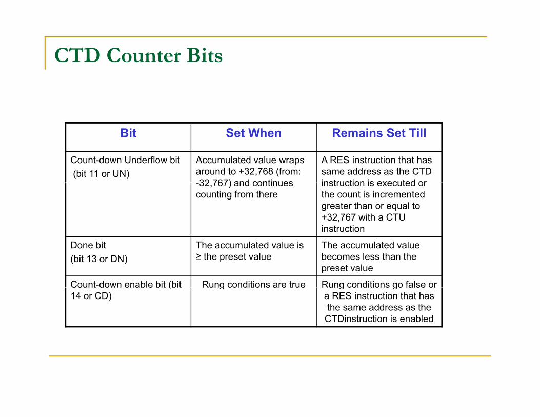
CTD Counter Bits
Bit S t Wh R i S t TillBit Set When Remains Set Till
Count-down Underflow bit(bit 11 or UN)
Accumulated value wraps around to +32,768 (from: 32 767) and continues
A RES instruction that has same address as the CTD instruction is executed or-32,767) and continues
counting from thereinstruction is executed or the count is incremented greater than or equal to +32,767 with a CTU instruction
Done bit(bit 13 or DN)
The accumulated value is ≥ the preset value
The accumulated value becomes less than the preset value
Count-down enable bit (bit Rung conditions are true Rung conditions go false orCount down enable bit (bit 14 or CD)
Rung conditions are true Rung conditions go false or a RES instruction that has the same address as the CTDinstruction is enabled

Memory StorageCTU and CTD Counter Bits
15 14 13 12 11 10 9 8 7 6 5 4 3 2 1 0Bits Element
CU CD DN OV UN Internal UsePreset Value
Accumulated Value
0 C5:0
1 C5:0.PRE
2 C5:0 ACC
Bits
Count Up (CU), Count Down (CD), Done (DN), Overflow (OV) and Underflow (UN) bits are stored in first 16 bits
The CPU sets the OV bit when the counter exceeds upper limit +32 767
Accumulated Value 2 C5:0.ACC
The CPU sets the OV bit when the counter exceeds upper limit +32,767 ACC wraps around to -32,767 and continues incrementing from there towards
zero to +32,767 The CPU sets the UN bit when the counter exceeds lower limit -32,767
ACC d t 32 767 d ti d ti f th t d ACC wraps around to +32,767 and continues decrementing from there towards zero to -32,767
PRE value is held in the second 16 bit of counter storage Third 16 bit holds accumulated value of counter
Computer Aided Manufacturing TECH 4/53350 35

Cascading CountersCTU
COUNT UPCounter C5:0Preset 24Accum 0
ENI:2.0
1 DN
COUNT UPCounter C5:1Preset 5000Accum 257
CTUEN
DN
C5:0
DN
RES
Accum 257DN
C5:0
Two counters are used to extend the count Counter C5:0 is used to count 24 cans for each case
When C5:0 ACC value ≥ 24, DN bit is set The CTU C5:0/DN energizes CTU C5:1
The C5:1 Acc value is incremented to count number of cases of 24 cans
36
The ladder diagram shows 257 cases of 24 cans