chapter 5 shaping and forming - home - almet marine · the tools and forming techniques ... blade...
TRANSCRIPT
73
Alcan
Mari
ne
1. Receiving and storage of semis . . . . . . . . . . . . . . . . . . . . . . . . . . . . . . . . . . . . . . . . . . . . . . . . . . . 741.1 Receiving packs . . . . . . . . . . . . . . . . . . . . . . . . . . . . . . . . . . . . . . . . . . . . . . . . . . . . . . . . . . . . . . . . . . . 751.2 Storage . . . . . . . . . . . . . . . . . . . . . . . . . . . . . . . . . . . . . . . . . . . . . . . . . . . . . . . . . . . . . . . . . . . . . . . . . 75
2. Cutting to shape . . . . . . . . . . . . . . . . . . . . . . . . . . . . . . . . . . . . . . . . . . . . . . . . . . . . . . . . . . . . . . . . 762.1 Plate and crocodile shears . . . . . . . . . . . . . . . . . . . . . . . . . . . . . . . . . . . . . . . . . . . . . . . . . . . . . . . . . . . 762.2 Bandsaw . . . . . . . . . . . . . . . . . . . . . . . . . . . . . . . . . . . . . . . . . . . . . . . . . . . . . . . . . . . . . . . . . . . . . . . . 762.3 Circular saw . . . . . . . . . . . . . . . . . . . . . . . . . . . . . . . . . . . . . . . . . . . . . . . . . . . . . . . . . . . . . . . . . . . . . . 772.4 Plasma cutting . . . . . . . . . . . . . . . . . . . . . . . . . . . . . . . . . . . . . . . . . . . . . . . . . . . . . . . . . . . . . . . . . . . . 772.5 Fluid jet cutting . . . . . . . . . . . . . . . . . . . . . . . . . . . . . . . . . . . . . . . . . . . . . . . . . . . . . . . . . . . . . . . . . . . 79
3. Forming . . . . . . . . . . . . . . . . . . . . . . . . . . . . . . . . . . . . . . . . . . . . . . . . . . . . . . . . . . . . . . . . . . . . . . . . 793.1 Influence of the temper . . . . . . . . . . . . . . . . . . . . . . . . . . . . . . . . . . . . . . . . . . . . . . . . . . . . . . . . . . . . . 793.2 Sheet bending . . . . . . . . . . . . . . . . . . . . . . . . . . . . . . . . . . . . . . . . . . . . . . . . . . . . . . . . . . . . . . . . . . . . 793.3 Non-machinable surfaces . . . . . . . . . . . . . . . . . . . . . . . . . . . . . . . . . . . . . . . . . . . . . . . . . . . . . . . . . . . . 803.4 Bending tubes and shapes . . . . . . . . . . . . . . . . . . . . . . . . . . . . . . . . . . . . . . . . . . . . . . . . . . . . . . . . . . . 80
C h a p t e r 5S H A P I N G A N D F O R M I N G
73

74
Alcan
Mari
ne
THE SHAPING and forming ofaluminium alloy semi-finished
products for use in shipbuilding andmarine applications comprises all ofthe operations prior to assemblyby welding, riveting and bonding.These are: marking out prior to cutting, ifrequired, cutting to shape and size beforeassembly, forming.
The development of computer soft-ware for naval architecture and shipdesign has made it possible to auto-mate metal cutting operations.These operations may be carried outby the shipyard or by a sub-contrac-tor who specialises in this activity.
This preparatory phase of formingmust be conducted with extremecare, especially with regard to cut-ting. Cutting must be both asaccurate as possible to ensure agood fitup of components that willbe welded together, and as regularas possible to prevent any sites ofcrack initiation. Cutting quality isone of the parameters that deter-mines the fatigue strength ofwelded joints.
The surface hardness of aluminiumis less than that of steel. This factormust be taken into considerationwhen handling semis, whenclamping components in machinejaws and during certain formingoperations, to prevent scoring orbruising to the metal. Aluminiumsheet must never be draggedalong the ground, placed in thepath of handling equipment suchas stacker trucks, or walked on.
Aluminium alloy semis must beprotected from metal particles dis-charged by the forming or shaping(grinding, machining etc.) of othermetals such as steels or copperalloys. Such particles can causesuperficial micro-pitting in thepresence of moisture if allowed tobecome embedded in the surfaceof the aluminium.
The tools and forming techniquesused for aluminium alloys do notdiffer greatly from those used forstainless steel. However certainsettings (or arrangements) of tool-ing are different, for example bend-ing radii or the angles of sawteeth.
1.RECEIVING ANDSTORAGE OF SEMIS
Packaging to the size of the fin-ished product is made of timber orsteel pallets on which sheets arestacked. These may be separatedfrom one another by liners madefrom special moisture-absorbentpaper.
The packs of aluminium sheet arewrapped in polyethylene film andKraft paper and strapped to thepallet (figure 53).
5 . S H A P I N G
74
COASTGUARD CP 280

75
Alcan
Mari
ne
1.1Receiving packs
Polymer film and Kraft paper cantear, which means that these pack-aging materials are not watertightand incoming packs of aluminiumalloy semis must be unwrappedunder cover.
Aluminium sheet must be handledwith care and precautions taken toprotect its clean surface conditionto ensure the good quality of weld-ments and the general appearanceof aluminium alloy structures.
1.2Storage
There is no compelling need toremove aluminium semi productsfrom their original packagingbefore they are actually needed.They just have to be protectedfrom water and damp environ-ments at their place of storage.
However if sheets or shapes areremoved from their original pack-aging and stored flat, they must beplaced on wooden blocks severalcentimetres thick to prevent any
direct contact with the ground,even if this is cemented. When sheets or shapes are laidflat without any liners betweenthem (paper or board or evenwooden blocks), whitish or green-ish stains on facing surfaces willusually be observed after a certainperiod of time (1). These stains aredue to the effect of moisture seep-ing in between the sheets orshapes by capillary action.
Prolonged storage of unpackedsemis in the open air can lead tosuperficial changes on the surfaceof the material. These will usuallybe very superficial micro-pits (afew microns in size), stains oreven general tarnishing (2).
While such alterations have noeffect on the metal’s subsequentresistance to corrosion, when theyare in service on the ship they rep-resent moisture “traps” that mustbe carefully removed before anywelding. They will affect the gen-eral appearance of the semis how-ever, though this is less criticalwhen the products are painted orcannot be seen from the outside.
Note: Ideal storage is in a coveredroom protected from the weather,with semis stocked upright andsheets or shapes spaced apart toprevent moisture penetratingbetween them. When stored flat,semis should be spaced apartusing wooden blocks.
A N D F O R M I N G
75
PACKING "MARINE" GRADE SHEET
Figure 53
(1) These stains will have the sameshape on both of the facing surfaces.They are symmetrical about the axisparallel with the sides of the sheets (orshapes).(2) It goes without saying that thesechanges will be made worse inaggressive atmospheres highly pollutedby industrial emissions, smoke etc.
FLYINGCAT 3

76
Alcan
Mari
ne
2.CUTTING TO SHAPE
The basic tools used for cuttingaluminium alloys are the same asfor steel. These are: plate or crocodile shears, bandsaw, circular saw, plasma, fluid jet.
The first three tools (and plasma)are used for manual cutting,whereas plasma and fluid jet arethe preferred media when cuttingis automated using programmescreated with naval constructionsoftware.
The contours of the parts mustfirst be traced on the semi beforethey are cut out. Metal scribingtools should not be used for trac-ing as they can leave marks in thematerial which could becomecrack initiation sites under theeffect of stresses in service.
It is preferable to use a mediumhard pencil (e.g. 5H) (3) that makeslines which are very visible andeasy to erase if corrections arenecessary.
2.1Plate and crocodileshears
These shears are used for makingstraight-line cuts. Aluminium alloysare cut with machines of the samepower as for unalloyed steel E24.
The surface condition of the edgeof the shear blade must also be asclean as possible. A roughness Raof less than 0.1 micron on a steelblade of type Z160CDV12 min-imises the risks of seizing.
A suitable “cutting gap” or clear-ance should be set between theblade and the frame of the shearto protect sheet from distortion.The optimum setting will increasewith the metal’s shearstrength; the gap will also besmaller for annealed sheet than forstrain hardened sheet.
The use of shears to cut sheetmore than 10 mm thick is notadvisable in practice, as cuttingintroduces stresses on thesheared edges that can ultimatelylead to severe pitting corrosionand also cause cracks.
2.2Bandsaw
A bandsaw is essential for cuttingsheet more than 10 mm thick andfor shapes.
Sawblades used for cutting alu-minium are special – their teethhave a greater pitch (i.e. there ismore space between adjacentteeth) and a wider throat thanblades used to saw steel (figure54) so as to assist chip fragmenta-tion and removal.
The pitch of the teeth must besuch that two teeth are engaged inthe thickness of the metal at alltimes, so there is a minimumthickness of material that is suit-able for cutting with this tool.
The rate at which aluminium issawn is greater than for steel, andmay attain 1000 mm.min-1.Lubrication using soluble oil or cut-ting oil is essential for long lengthsand high cutting rates.
Sawing will produce cut edgesthat are clean and burr-free pro-vided the sawblade is suitable foraluminium and the cutting parame-ters are set correctly.
Note: Jigsaws can be used to cutthin sheet less than 6 mm thick;jigsaws have the advantage ofbeing very easy to handle and canbe used to cut relatively complexshapes as well as straight lines.
76
BANDSAW
2,5 to 8 mm 1,8 t
3° à 0°55°
t
Figure 54
(3) Graphite markers should not be usedon surfaces which will be in contact withwater or moisture.

77
Alcan
Mari
ne
2.3Circular saw
Also called a milling saw by some,it operates with an action similarto milling.
The characteristics of circular sawblades for aluminium are shown infigure 55.
With semi-finished products in the5000 and 6000 series, cuttingspeeds can attain 600 to 1000mm/min. with high speed steel(HSS) blades and 800 to 1500mm/min. using carbide blades.
As with the bandsaw blade, lubri-cation is essential for long cutsand high cutting speeds.
The values of p and h will dependon the diameter of the saw
Note: Portable circular saws maybe used on products not morethan 20 mm thick.
2.4Plasma cutting
The industrial use of plasma cut-ting for metals began in theNineteen Fifties.
In this process, the cutting of themetal is achieved with a combina-tion of the thermal and kineticeffects of a plasma arc which isgenerated by a special torchwhose path follows the contoursof the piece that is to be cut.
The plasma arc is obtained by pass-ing an electric current through astream of gas, also known as plas-magen gas, that has been broughtup to ionisation temperature.
To obtain the characteristics thatare required for cutting, the plasmaarc is passed through a smalldiameter energy-cooled apertureor nozzle, the containing effect ofwhich is to greatly increase thetemperature and velocity of theresulting jet of plasma arc.
As an indication, the current flow-ing in the column of plasma arccan be between 10 and 1000Amps, the diameter of the jetemerging from the nozzle rangesfrom several tenths of a millimetreto several millimetres, the temper-ature inside the jet from 15,000 to
30,000 K and the discharge veloc-ity at the exit from the nozzle fromMach 1 to Mach 2.
The process of the plasma cut-ting of metal materials is basedon a transferred arc, whichmeans that an arc is establishedbetween a refractory electrode (–pole) and the piece to be cut (+pole) (figure 56).
This highly rigid and extremely hotstream of plasma fuses the metalover its full thickness and ejects itoutside the cut thanks to thekinetic energy generated by theplasma’s very high velocity.
The choice of gas depends on thethickness of the material that is tobe cut and on other criteria suchas the quality of cut, productivityand running costs (table 45, p. 78).
Plasma cutting can be manualwith the compressed air andargon/hydrogen processes, orautomatic (on machines).
Manual plasma cutting is used pri-marily on site to make unplannedcuts, e.g. breaches for pipesthrough bulkheads, partitions etc.A template should be used foraccurate cutting. Material up to50 mm thick can be cut manuallyand with a limited amount of skill.
5. SHAPING AND FORMING
77
CIRCULAR SAW
25°
hp
d
t–3t–3
tt
60° 60°
d : draw of 8°over 1 mm of width
p and h are in relation with the saw diameter
Figure 55
PLASMA CUTTING
-
+
R
A
B
Plasmagen gas
Coolingwater
Tungsten electrode
Figure 56

78
Alcan
Mari
ne
Automatic plasma cutting isdone on straight or contouredcutting tables (such as numeri-cally controlled (NC) X-Ymachines or multiple jointedrobots). The path of the plasmatorch is controlled by machineaxis control programmes; theserun in conjunction with softwarethat defines the geometry of thecomponents and their interfaceswith other parts so as to min-imise waste by optimising boththe position of the componentwithin the sheet format and thepaths of the torch.
There are two plasma cutting tech-niques (figure 57):
- “dry” plasma cutting on a table,in air. The draft may be as much as5° with a plasmagen gas mixtureof argon and hydrogen,
- water vortex plasma, in which thesheet to be cut is placed in a tankfilled with water. The torch itself ispartially submerged. The cuttingdraft is smaller, in the region of 2to 3° (4).
Water vortex plasma allows highercutting speeds than argon/hydro-gen plasma cutting which is donein air. It demands more electricalpower for the same thickness ofcut however. Argon/hydrogen canbe used to cut material thick-nesses of up to 150 mm, and thegeometrical accuracy of the cutpieces is in the region of 1 mil-limetre.
Given the high energy input thattakes place during the localisedfusion of the metal, heat is dif-fused to a width of around onemillimetre on either side of the cutwhatever the alloy and whateverits thickness. As happens with arcwelding (5), this “heat affectedzone” is annealed (in the metallur-gical sense).
This zone can be removed bymachining more than 2 mm fromthe cut edge, although this opera-tion is obviously pointless whenthe piece has been cut to size andshape for subsequent arc welding.
Note: The process of oxygen cut-ting with the oxy-acetylene torchwhich is used widely for mild steelis not at all suitable for aluminium.
78
PLASMAGEN GASESThickness (mm) Gas Remarks
0,4 - 15 Oxygen High cutting speeds0,4 - 30 Compressed air Low running costs8 – 150 Mixture
Argon (80 to 65 %) / Hydrogen (20 to 35 %) Superior cut quality 1 – 70 Nitrogen + Post injection of water Immersing the component in water reduces sources
of nuisance (noise, fumes and radiation)Table 45
PRINCIPLE OF PLASMA
+ +
-
Coolingwater
Electrode
Plasmagen gasPlasmagen gas
Electrode
Water cone
Plasma columnVortex water inlet
Plasma in vortex Plasma in free air
-
Figure 57
(4) During water vortex plasma cutting,the fine particles of aluminium can reactwith the water and give off hydrogen. Itis therefore essential to avoid any build-up of this gas which can cause localexplosions.(5) Cf. Chapter 6.

79
Alcan
Mari
ne
2.5Fluid jet cutting
In fluid jet cutting, the metal is cutby a calibrated jet of watercharged with abrasive particles(granules of garnet, corundum orother very hard minerals). Thewater is projected at very highpressure - 3000 bars and more -through a nozzle onto the materialwhich is in a tank filled with water(figure 58).
Water jet cutting produces a cleanand extremely accurate cut with-out a draft.
On aluminium, the technique canbe used to cut through thick-nesses between 1 and 100 mm atspeeds of 3500 and 30 mm/minrespectively.
Unlike plasma cutting, there is noheat affected zone either side ofthe cut because no heat is trans-ferred.
3.FORMING
In naval construction, forming con-sists essentially of the folding andforming of sheet and the bendingof shapes.
Because forming requires themetal to be sufficiently plastic, itfollows that the temper of alu-minium alloy semis is an importantparameter that must be taken intoconsideration for delivery and dur-ing the forming operations if theseinvolve significant work hardening.
3.1Influence of the temper
Most aluminium alloys used inshipbuilding and in coastal installa-tions belong to:
the 5000 series (aluminium-magnesium alloys), mainly in theform of sheet and plate. The mostcommon alloys are: 5754, 5086,5086, 5383. These alloys lend them-selves very well to forming espe-cially in the annealed tempers Oand annealed flattened tempersH111. It is these tempers whichshould be preferred as having thebest suitability for forming. This sui-tability decreases for the H116 tem-per and even more so for the H321. the 6000 series (aluminium—sili-con-magnesium alloys), mainly inthe form of shapes. The most com-mon alloys are: 6005A, 6082 and6061. As in all the 6000 series,these are age hardened alloys.Semis are delivered in the T6 or T5tempers and less frequently in theT4 or T1 tempers (6). Even thoughthese alloys lend themselves lesswell to forming in the artificiallyaged tempers (T6 or T5), they mustnevertheless be formed cold andnot hot. Heating would have amore or less marked annealingeffect and hence a significantreduction in mechanical properties.
3.2Sheet bending
Conventional table bendingmachines and bending presses areperfectly adequate provided thetools are free from unacceptableirregularities.
If for reasons of appearance thebent sheet must not display anyclamp marks from the jaws, thenthe contact surfaces should beprotected with kraft paper or plas-tic film.
For multiple bendings, holesshould be drilled to mark theirpoints of intersection to avoid theformation of cracks during bending(figure 59). The hole diameter willincrease with the thickness of thematerial. It is 4 mm for sheet 1mm thick and 6 mm for material 2mm thick.
Aluminium alloys must never bebent at a sharp angle. The insideradius of bending is a function ofthe thickness of the sheet to bebent (table 46):
Note: Aluminium alloy sheet (orshapes) from which forms havealready been cut out should neverbe formed. Cutouts must alwaysbe made after forming, using a jig-saw for example.
5. SHAPING AND FORMING
79
WATER JET CUTTING
High pressure waterHigh speed jet
Injection ofabrasiveAccelerationand focusingFocused jet
Materialbeing cut
Collector
Figure 58
(6) For the meaning of the tempers, referto section 4.3 in Chapter 3.
INTERSECTING BENDINGS
Relief hole
Figure 59

80
Alcan
Mari
ne
3.3Non-machinablesurfaces
All scoring or clamping marks leftbehind after cutting must beremoved from the edges of sheetmaterial to prevent the formationof cracks at points of deep defor-mation.
If the material is so work hardenedthat shaping becomes difficult,intermediate annealing must becarried out either in the furnace orusing an oxy-acetylene torch.
In this case the rise in temperaturemust be monitored. Tallow can beused as a temperature indicator –it turns brown around 340 °C – oruse thermocolour pencils thatchange colour as the temperaturechanges.
3.4Bending tubes and shapes
Bending can be carried out manu-ally on timber templates for slen-der sections or steel templates forthicker sections. If necessary,tubes are filled with sand andshapes are internally reinforced toprevent collapse or distortion.
Bending can also be done on suit-able presses (three-roll bendingpress etc.).
6000 series alloys in the T6 tempershould be bent cold so as not toaffect their mechanical propertiesin the delivery condition. If this isnot possible, they will have to bebent in the quenched T1 or T4 tem-per and then artificially aged underthe usual conditions of tempera-ture and time.
80
INSIDE RADII FOR COLD BENDING, AT 90 °TYPICAL VALUES (*)Alloy Thickness (mm)
Temper 1,5 - 3,0 3,0 - 6,0 6,0 - 12,5 5454 O and H111 1,0 t 1,5 t 2,5 t
H24 and H34 2,5 t 3,0 t 4,0 t 5754 O and H111 1,0 t 1,0 t 2,0 t
H24 and H34 2,0 t 2,5 t 3,0 t 5083 O and H111 1,0 t 1,5 t 2,5 t
H116 2,0 t 2,5 t 4,0 t H24 and H34 2,5 t 3,5 t 4,5 t
5383 O and H111 1,0 t 1,5 t 2,5 t H116 2,0 t 2,5 t 4,0 t
H24 and H34 2,5 t 3,5 t 4,5 t 5086 O and H111 1,0 t 1,5 t 2,5 t
H116 2,0 t 2,5 t 3,5 t H24 and H34 2,5 t 3,5 t 4,5 t
6061 O 1,0 t 1,0 t 2,0 t T6 (**) 3,5 t 4,0 t 5,0 t
6082 O 1,0 t 1,5 t 2,5 t T6 (**) 3,5 t 4,5 t 6,0 t
(*) Taken from standard EN 485-2, December 2001. Table 46(**) Sheet made from these alloys can be bent to significantly smaller radii on a "fresh quench".

81
Alcan
Mari
ne
5. SHAPING AND FORMING
HIGH INERTIA BEAM FABRICATED BY WELDING SHEETS
82
Alcan
Mari
ne
PATROL BOATS

83
Alcan
Mari
ne
1. Historical review . . . . . . . . . . . . . . . . . . . . . . . . . . . . . . . . . . . . . . . . . . . . . . . . . . . . . . . . . . . . . . . . 842. Specifics of welding aluminium. . . . . . . . . . . . . . . . . . . . . . . . . . . . . . . . . . . . . . . . . . . . . . . . . . . 852.1 The oxide film . . . . . . . . . . . . . . . . . . . . . . . . . . . . . . . . . . . . . . . . . . . . . . . . . . . . . . . . . . . . . . . . . . . . 852.2 Solubility of hydrogen in the fused metal . . . . . . . . . . . . . . . . . . . . . . . . . . . . . . . . . . . . . . . . . . . . . . . . 862.3 Physical properties . . . . . . . . . . . . . . . . . . . . . . . . . . . . . . . . . . . . . . . . . . . . . . . . . . . . . . . . . . . . . . . . . 862.4 The heat affected zone (HAZ) . . . . . . . . . . . . . . . . . . . . . . . . . . . . . . . . . . . . . . . . . . . . . . . . . . . . . . . . . 872.5 Weldable aluminium alloys . . . . . . . . . . . . . . . . . . . . . . . . . . . . . . . . . . . . . . . . . . . . . . . . . . . . . . . . . . . 883. Implications for the design and execution of welds . . . . . . . . . . . . . . . . . . . . . . . . . . . . . . . . . 893.1 Distortion . . . . . . . . . . . . . . . . . . . . . . . . . . . . . . . . . . . . . . . . . . . . . . . . . . . . . . . . . . . . . . . . . . . . . . . . 893.2 Stresses . . . . . . . . . . . . . . . . . . . . . . . . . . . . . . . . . . . . . . . . . . . . . . . . . . . . . . . . . . . . . . . . . . . . . . . . 903.3 Controlling distortion . . . . . . . . . . . . . . . . . . . . . . . . . . . . . . . . . . . . . . . . . . . . . . . . . . . . . . . . . . . . . . . 903.4 Use in the fabrication of a section with stiffeners . . . . . . . . . . . . . . . . . . . . . . . . . . . . . . . . . . . . . . . . . . 924. Arc welding processes . . . . . . . . . . . . . . . . . . . . . . . . . . . . . . . . . . . . . . . . . . . . . . . . . . . . . . . . . . . 934.1 TIG welding (Tungsten Inert Gas) . . . . . . . . . . . . . . . . . . . . . . . . . . . . . . . . . . . . . . . . . . . . . . . . . . . . . . 934.2 MIG welding (Metal Inert Gas) . . . . . . . . . . . . . . . . . . . . . . . . . . . . . . . . . . . . . . . . . . . . . . . . . . . . . . . . 944.3 Synergic pulsed MIG . . . . . . . . . . . . . . . . . . . . . . . . . . . . . . . . . . . . . . . . . . . . . . . . . . . . . . . . . . . . . . . 944.4 "Spray MODAL" synergic MIG with modulated current . . . . . . . . . . . . . . . . . . . . . . . . . . . . . . . . . . . . . . 964.5 Filler wires . . . . . . . . . . . . . . . . . . . . . . . . . . . . . . . . . . . . . . . . . . . . . . . . . . . . . . . . . . . . . . . . . . . . . . . 965. Storage of semi-finished products and filler wire . . . . . . . . . . . . . . . . . . . . . . . . . . . . . . . . . . 976. Surface preparation . . . . . . . . . . . . . . . . . . . . . . . . . . . . . . . . . . . . . . . . . . . . . . . . . . . . . . . . . . . . . 987. Joint preparation and setup . . . . . . . . . . . . . . . . . . . . . . . . . . . . . . . . . . . . . . . . . . . . . . . . . . . . . . 988. Filler metal . . . . . . . . . . . . . . . . . . . . . . . . . . . . . . . . . . . . . . . . . . . . . . . . . . . . . . . . . . . . . . . . . . . . . 989. Finishing . . . . . . . . . . . . . . . . . . . . . . . . . . . . . . . . . . . . . . . . . . . . . . . . . . . . . . . . . . . . . . . . . . . . . . 1009.1 Repair of defective welds . . . . . . . . . . . . . . . . . . . . . . . . . . . . . . . . . . . . . . . . . . . . . . . . . . . . . . . . . . . 1019.2 Cleaning . . . . . . . . . . . . . . . . . . . . . . . . . . . . . . . . . . . . . . . . . . . . . . . . . . . . . . . . . . . . . . . . . . . . . . . . 1029.3 Correcting distortion . . . . . . . . . . . . . . . . . . . . . . . . . . . . . . . . . . . . . . . . . . . . . . . . . . . . . . . . . . . . . . . 1029.4 Shaving . . . . . . . . . . . . . . . . . . . . . . . . . . . . . . . . . . . . . . . . . . . . . . . . . . . . . . . . . . . . . . . . . . . . . . . . 1029.5 Shot-peening . . . . . . . . . . . . . . . . . . . . . . . . . . . . . . . . . . . . . . . . . . . . . . . . . . . . . . . . . . . . . . . . . . . . 10210. Inspection . . . . . . . . . . . . . . . . . . . . . . . . . . . . . . . . . . . . . . . . . . . . . . . . . . . . . . . . . . . . . . . . . . . . 10310.1 Approval procedures . . . . . . . . . . . . . . . . . . . . . . . . . . . . . . . . . . . . . . . . . . . . . . . . . . . . . . . . . . . . . . 10310.2 Testing welded joints . . . . . . . . . . . . . . . . . . . . . . . . . . . . . . . . . . . . . . . . . . . . . . . . . . . . . . . . . . . . . 10311. Weld imperfections . . . . . . . . . . . . . . . . . . . . . . . . . . . . . . . . . . . . . . . . . . . . . . . . . . . . . . . . . . . . 10311.1 Common weld imperfections . . . . . . . . . . . . . . . . . . . . . . . . . . . . . . . . . . . . . . . . . . . . . . . . . . . . . . . 10411.2 Effect of weld imperfections on fatigue strength . . . . . . . . . . . . . . . . . . . . . . . . . . . . . . . . . . . . . . . . . 10512. Repairs and fittings . . . . . . . . . . . . . . . . . . . . . . . . . . . . . . . . . . . . . . . . . . . . . . . . . . . . . . . . . . . 10613. Laser welding . . . . . . . . . . . . . . . . . . . . . . . . . . . . . . . . . . . . . . . . . . . . . . . . . . . . . . . . . . . . . . . . 10613.1 Principle of the laser . . . . . . . . . . . . . . . . . . . . . . . . . . . . . . . . . . . . . . . . . . . . . . . . . . . . . . . . . . . . . . 10613.2 Welding lasers . . . . . . . . . . . . . . . . . . . . . . . . . . . . . . . . . . . . . . . . . . . . . . . . . . . . . . . . . . . . . . . . . . 10613.3 Laser welding of aluminium alloys . . . . . . . . . . . . . . . . . . . . . . . . . . . . . . . . . . . . . . . . . . . . . . . . . . . 10713.4 Laser weldability of aluminium alloys . . . . . . . . . . . . . . . . . . . . . . . . . . . . . . . . . . . . . . . . . . . . . . . . . 10714. Friction Stir Welding (FSW) . . . . . . . . . . . . . . . . . . . . . . . . . . . . . . . . . . . . . . . . . . . . . . . . . . . . 10814.1 Principle of friction stir welding . . . . . . . . . . . . . . . . . . . . . . . . . . . . . . . . . . . . . . . . . . . . . . . . . . . . . . 10814.2 Microstructure of the FSW joint . . . . . . . . . . . . . . . . . . . . . . . . . . . . . . . . . . . . . . . . . . . . . . . . . . . . . 10814.3 Comparisons with arc welding . . . . . . . . . . . . . . . . . . . . . . . . . . . . . . . . . . . . . . . . . . . . . . . . . . . . . . 10914.4 Possibilities of welding with FSW . . . . . . . . . . . . . . . . . . . . . . . . . . . . . . . . . . . . . . . . . . . . . . . . . . . . 11014.5 Performance of FSW welds . . . . . . . . . . . . . . . . . . . . . . . . . . . . . . . . . . . . . . . . . . . . . . . . . . . . . . . . . 11115. Standards . . . . . . . . . . . . . . . . . . . . . . . . . . . . . . . . . . . . . . . . . . . . . . . . . . . . . . . . . . . . . . . . . . . . 112
C h a p t e r 6W E L D I N G
83

84
Alcan
Mari
ne
W ELDING is the process bywhich two or more parts
are joined by localised fusion ofthe metal to form a single com-ponent; the original contours ofthe initial parts disappear afterassembly.
Arc welding is still by far the mostwidespread joining process andthe one used most frequently inshipbuilding.
Technical advances in arc weld-ing with pulsed MIG havehelped improve the perform-ance of welding machines andthe quality of the weldmentsproduced.
The development of other processessuch as laser beam welding or fric-tion stir welding (FSW) will furtheradvance the design and fabricationof aluminium sub-assemblies forshipbuilding.
Whatever the welding techniquethat is used, the quality of work-manship of aluminium alloy weld-ments becomes increasinglyimportant on very long ships as itdetermines the fatigue resistanceof the most stressed areas of thevessel. The weld is a vital elementin the fatigue strength of anassembly.
1.HISTORICAL REVIEW
The first attempts at welding alu-minium were made in 1904, andgas welding was used at thattime [1].
Up until the early Sixties, weldingwith the oxy-acetylene torch wasthe only method available for weld-ing aluminium alloys. The use ofthis process was limited to flatwelding and thin sheet.
For many years the presence of anatural oxide film on the surface ofaluminium was a major obstacle tothe welding of this metal. For alu-minium to be welded correctly,this film must be removed andprevented from re-forming byshielding the weld pool from thesurrounding atmosphere.
In oxy-acetylene welding, fluxesin the form of paste diluted inwater were deposited on theedges to be welded and on thefiller wire to eliminate the oxidefilm. These fluxes were based onchlorides and fluorides. To avoidany risk of corrosion from fluxresidues, these had to beremoved by brushing or washingin water.
As with the arc welding of steel,rods of filler metal coated in fluxfor welding thicker products beganto become available from 1925onwards. One of the very firstknown applications of arc weldingusing coated rods came in Francein 1934 with the construction ofrailway vehicles in 5056 (A-G5)alloy for the ‘Cie Française desChemins de Fer du Nord’ [2]. Thisprocess was not developed to anygreat extent owing to the unsatis-factory quality of the weldments.
The first attempts at arc welding ina shielding gas (argon or helium)were made in the middle of theNineteen Thirties [3]. This techniquerepresented a major step forward,and eliminated the need for fluxwith its attendant risks of corro-sion. It was now possible to weldat high speed and in all positions,making aluminium a “fullyfledged” fabrication metal in itsown right.
The industrial development of theTIG and MIG processes began inthe early Fifties and advances andimprovements in these processeshave been made ever since. Onesuch innovation came at the begin-ning of the Nineties with electroni-cally controlled pulsed MIG welding.
6 . W E L D I N G
84
WELDING A HATCHWAY FRAME

85
Alcan
Mari
ne
Up until the early Sixties, shipsmade from aluminium alloys – aswell as aluminium alloy equipmenton steel ships (superstructures,funnels etc.) – were assembled bymeans of riveting, as indeed steelships still were.
The sailing ship “Morag Mhor”, a70 foot ketch made from alu-minium-magnesium alloy (4 and 5% magnesium) and designed by aBritish naval architect, was thefirst known boat to be constructedwith MIG welding in 1953 [4].
2.SPECIFICSOF WELDINGALUMINIUM
Although the techniques used forwelding semi-finished productsmade from aluminium alloys arevery similar to and even the sameas those used for carbon steel, theoperating conditions are ratherdifferent. This is due to thepresence of the oxide film (Al2O3)on the surface of the metal (1) andto the physical properties ofaluminium alloys which are verydifferent from those of steels(table 47, p. 87).
2.1The oxide film
The natural film of oxide whichpermanently covers the surface ofthe metal is 50 to 100 nanometersthick. Its melting point is very high,2052 °C, and it is insoluble in solidor liquid aluminium.
For welding purposes the filmmust be removed (2) andprevented from re-forming whilethe filler metal is being applied tothe weld seam (3). This is whyaluminium must be arc welded orlaser welded in a controlledatmosphere consisting of an inertgas such as argon, helium or theirmixtures.
Although the film is chemicallystable (it is an oxide) it neverthelessreacts with its environment byadsorbing traces of rolling mill oils,shaping lubricants and themoisture present in the air. All ofthese elements are sources ofhydrogen (4) when they aredissociated in the plasma of theelectric arc.
85
(1) Cf. Chapter 10.(2) In arc welding with the continuousTIG process, the welded piece is alwaysconnected to the minus pole (–) toremove the oxide film.(3) Although it is an electrical insulator,the film is too thin to stop the flow ofelectrical current in the same way aslayers of anodising whose thickness iscommonly 15 to 20 microns.(4) Greases and lubricants are carbonchains with the general formula CnH2nO.
LNG CARRIERS

86
Alcan
Mari
ne
2.2Solubility of hydrogen in thefused metal
Given the very high solubility ofhydrogen in liquid aluminium, itdissolves in the weld pool of theweld seam as it is formed (figure60) (5). However since hydrogen is solublein solid aluminium, if cooling is toofast it will have a tendency tobecome trapped in the metalforming bubbles that will beporosities in the weld seam (6).
This is why it is so important toremove all possible sources ofhydrogen on the metal that arepresent in moisture, in traces ofgrease and in the shielding gases.
2.3Physical properties
Table 47 presents a comparativelist of those physical properties ofaluminium and steel which affectthe welding of these metals. It isthe thermal properties whichaccount for the significant differ-ences between the welding condi-tions for aluminium comparedwith those for steel.
Aluminium has a high calorificcapacity (899 J.kg-1.K-1, comparedwith 420 for steel) and a higher ther-mal conductivity (229 W.m-1.K-1,against 78 for steel). This meansthat much of the energy inputfrom the arc is used to heat up thepieces that are to be welded.
Aluminium’s high effusivity (7)requires a very high level of weld-ing energy. All other things beingequal, the rise in temperature ofaluminium parts to be welded willbe greater than for steel parts.
Heat quickly dissipates in alu-minium due to its high diffusivity(8) (0.9 compared with 0.2 forsteel), and this must be compen-sated by the input of heat from theelectric arc.
Aluminium’s high coefficient ofexpansion (23.10-6), its high diffu-sivity and the metal’s high level oftemperature mean that welding isaccompanied by more strain in alu-minium than in other metals.
To maintain stable conditionstherefore, aluminium must bewelded at a rate higher than therate at which the heat is propa-gated (figure 61).
If carbon steels are cooled tooquickly they undergo a martensitictransformation that is accompa-nied by an increase in volumewhich in turn can cause cracks atthe base of the weld seam.
86
SOLUBILITY OF HYDROGEN
50
0,7
0,036660 2500
Meltingpoint
Boiling point
Solub
ility o
f hyd
rogen
(in cm
3 /100
g me
tal)
Solubility in liquid aluminium
Solubility in solid aluminium
Figure 60
(5) Contrary to what happens withcertain steels, hydrogen does notembrittle aluminium and does notsensitise it to stress corrosion.(6) Cf. table 54, pp. 104-105.(7) (7) Effusivity “b” is the product ofthermal conductivity λ by density ρ andby specific heat capacity cp :b = :λ.p.Cp.This variable describes the amount ofheat which a heated zone receives byconduction, where: λ = thermal conductivityρ = densityCp = calorific capacity.(8) hermal diffusivity “a” is defined bythe relation a = λ
ρ. Cp

87
Alcan
Mari
ne
There are no such changes withaluminium alloys. As a result, therapid cooling rate of the weld –between 100 and 1000 °C persecond – does not cause anydefect in the seam.
It is therefore not normallynecessary to preheat aluminiumprior to welding as can be donewith steel (to prevent cracks in theweldment during cooling).
All of these factors must beallowed for when designing jointsand executing the actual welds.This highly important aspect isdiscussed in Section 3.
2.4The heat affectedzone (HAZ)
With steels, changes of phasecause local hardening of the heataffected zone over a width ofseveral millimetres. In contrast,the effect of heating is to softenaluminium alloys when they are: in the strain hardened conditionas is the case with the 5000 alloysin the H116, H24, H32 and H34tempers, thermally treated, e.g. 6000alloys in the T5 or T6 tempers.
As figure 62, p. 88, shows, thematerial’s mechanical propertieschange gradually from the weldseam outward to the edges of theHAZ (9).
As a result, the mechanicalproperties of the weldment areusually inferior to those of theparent metal. They are near to theannealed condition for strainhardened alloys and to the T4temper for age hardening alloys.
6. WELDING
87
PHYSICAL PROPERTIES OF ALUMINIUM AND STEEL E24Property Unalloyed Aluminium (1050A) Steel E24 Ratio Al/Steel
Fusion interval (°C) 645/658 1 400/1 530 Melting point of oxides (°C) 2 052 900 Solidification shrinkage (%) 1,7 1,2 1,4 Density (kg.m-3)2 700 7 820 0,34 Mass heat capacity Cp (J.kg-1.K-1) 899 420 2,14 Latent heat of fusion (kJ.kg-1) 385 210 1,83 Thermal conductivity (W.m-1.K-1) 229 54 4,24 Thermal diffusivity "a" (10-4.m2.sec-1) 0,9 0,2 4,5 Effusivity "b" (J. m-2.K-1.sec -1/2) 24 000 16 000 1,5 Coefficient of linear expansion α (10-6.K-1) 23,5 13,5 1,74 Electrical resistivity ρ (10-9 µ.Ω.m-1) 292 1010 0,29 Young’s modulus (MPa) 70 000 210 000 0,33
HEAT FLOW DURING WELDINGz
x
y
θy3
θy2θy1
θy0
Welding directionMaximum
temperature level
θx0θx1
θx2
Table 47
Figure 61
(9) The mechanical properties of theweld seam itself are usually superior tothose of the HAZ. When there is a crack,this usually occurs outside the weldseam.

88
Alcan
Mari
ne
This is why for stress calculations,the design codes and regulationsof the classification societiesspecify levels of yield strength ofthe annealed condition for strainhardening alloys and of the T4temper for age hardening alloys.
In the case of butt welds, the HAZis some 25 mm wide either side ofthe weld seam whatever thethickness of the parent metal andwhether TIG or MIG welding isused.
The impact on the mechanicalproperties of the weldment mustbe minimised by: selecting the filler metal that isbest suited to the parent alloy, establishing a welding cycle thatis as rapid as possible to limit thesize of the HAZ, designing the assembly so thatthe weldments are in the leaststressed positions.
2.5Weldable aluminiumalloys
Most of the alloys belonging to the1000, 3000, 5000 and 6000 seriescan be welded with the conven-tional TIG or MIG processes and bythe other energy beam processes– electron beam, laser etc.
The 5000 series is the one that ismost suitable for welding.
The wrought alloys containing cop-per in the 2000 and 7000 series(10) are not easy to arc weld (11).The presence of the coppercauses cracking and shrinkagecracks on the weld seam.
The weldability of castingsdepends more on the method ofcasting than on the chemical com-position of the alloy. Diecast partscannot be welded as they maycontain a lot of air that is intro-duced during the casting process.
Sand cast or chill cast parts can bewelded provided they are “clean”,i.e. free from porosities and shrinkholes that produce blisters in theweld seam (12).
The 42100 (A-S7G) and 43300 (A-S10G) alloys can be welded withalloys in the 6000 series (13).
88
HAZ
MECHANICAL CHARACTERISTICS OF THE HAZ
Rp0,2
Figure 62
(10) The 7000 alloys without copper suchas the 7020 can be welded but the HAZis very sensitive to exfoliating corrosion(cf. Chapter 10).(11) The welding regulations andconstruction codes such as Eurocode 9and standard BS 8118 actually excludethese alloys from arc weldedassemblies.(12) Porosities in sand castings can beavoided by the use of metal heat sinksthat improve the microstructure andprevent the formation of porosity.<0(13) The 5000 series cannot be weldedwith the 42000.
89
Alcan
Mari
ne
3.IMPLICATIONS FOR THE DESIGNAND EXECUTION OF WELDS
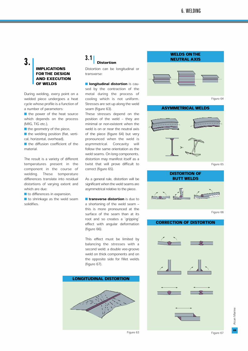
During welding, every point on awelded piece undergoes a heatcycle whose profile is a function ofa number of parameters: the power of the heat sourcewhich depends on the process(MIG, TIG etc.), the geometry of the piece, the welding position (flat, verti-cal, horizontal, overhead), the diffusion coefficient of thematerial.
The result is a variety of differenttemperatures present in thecomponent in the course ofwelding. These temperaturedifferences translate into residualdistortions of varying extent andwhich are due: to differences in expansion, to shrinkage as the weld seamsolidifies.
3.1Distortion
Distortion can be longitudinal ortransverse:
longitudinal distortion is cau-sed by the contraction of themetal during the process ofcooling which is not uniform.Stresses are set up along the weldseam (figure 63). These stresses depend on theposition of the weld – they areminimal or non-existent when theweld is on or near the neutral axisof the piece (figure 64) but verypronounced when the weld isasymmetrical. Concavity willfollow the same orientation as theweld seams. On long components,distortion may manifest itself as atwist that will prove difficult tocorrect (figure 65).
As a general rule, distortion will besignificant when the weld seams areasymmetrical relative to the piece.
transverse distortion is due toa shortening of the weld seam –this is more pronounced at thesurface of the seam than at itsroot and so creates a ‘gripping’effect with angular deformation(figure 66).
This effect must be limited bybalancing the stresses with asecond weld: a double vee-grooveweld on thick components and onthe opposite side for fillet welds(figure 67).
6. WELDING
89
LONGITUDINAL DISTORTION
WELDS ON THE NEUTRAL AXIS
ASYMMETRICAL WELDS
DISTORTION OFBUTT WELDS
CORRECTION OF DISTORTION
Figure 63
Figure 64
Figure 65
Figure 66
Figure 67
90
Alcan
Mari
ne
3.2Stresses
Local levels of stress can exceedthe yield strength of the metal,and are a function of: the shape of the piece, the layout of the weld seams, the weld sequence, positioning tools, clamping.
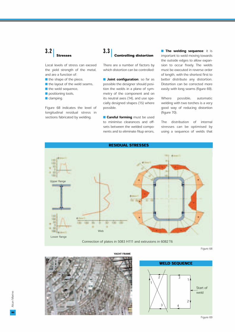
Figure 68 indicates the level oflongitudinal residual stress insections fabricated by welding.
3.3Controlling distortion
There are a number of factors bywhich distortion can be controlled:
Joint configuration: so far aspossible the designer should posi-tion the welds in a plane of sym-metry of the component and onits neutral axes (14), and use spe-cially designed shapes (15) wherepossible.
Careful forming must be usedto minimise clearances and off-sets between the welded compo-nents and to eliminate fitup errors,
The welding sequence: it isimportant to weld moving towardsthe outside edges to allow expan-sion to occur freely. The weldsmust be executed in reverse orderof length, with the shortest first tobetter distribute any distortion.Distortion can be corrected moreeasily with long seams (figure 69).
Where possible, automaticwelding with two torches is a verygood way of reducing distortion(figure 70).
The distribution of internalstresses can be optimised byusing a sequence of welds that
90
Connection of plates in 5083 H111 and extrusions in 6082 T6
Upper flange
Lower flangeWeb
RESIDUAL STRESSES
Figure 68
WELD SEQUENCE
2 31 1
243
Start ofweld
Figure 69
YACHT FRAME

91
Alcan
Mari
ne
WELDINGWITH TWO TORCHES
Torch
Torch
Figure 70
BUTT WELDINGSHAPES
2
3
1Weld sequence : 1, 2, 3
Figure 71
6. WELDING
induces residual compressionstresses in the weld seams thatare stressed in tension (figure 71).This approach will verysignificantly improve the fatiguestrength of the welded joints.
The purpose of clamping is tohold the parts in position.However clamps, fixtures etc.must not prevent expansion onthe longest axes or componentswill be stressed (with an attendantrisk of softening due to expansion∆l). Generally speaking, partsshould not be clamped in thedirections of greatest expansionas this will aggravate distortionsquare to the weld (figure 72).
On thick material, angular distortioncan be avoided by attachingtemporary stiffeners across theweld (figure 73).
Welding parameters: Distor-tion can also be caused by thesolidification shrinkage of theweld seam. The greater the quan-tity of fused metal and the higherthe temperature, the greater thisshrinkage will be. Distortion canbe limited by using high energyheat sources to weld as rapidlyas possible – the faster the wel-ding, the less time the heat hasto dissipate
Balance of heat flows: Long-itudinal distortion can be aggrava-ted by a thermal imbalance bet-ween the welded pieces. Thisimbalance can be due to:- the very different masses of thepieces that are to be joined,- misalignment as the weldingtorch moves, - poor contact with the support, - etc.
Whenever possible therefore, the“thermal masses” must be bal-anced to achieve good thermal sym-metry in the assembly (figure 74).
91
EFFECT OF CLAMPING
L0 = Initial lengthL1 = Final length
L0
L1
-∆l
-∆l
CLAMPING WITH STIFFENERSACROSS THE WELD
THERMAL BALANCEOF A WELD
Figure 72 Figure 73Figure 74
(14) This layout has a positive influenceon the fatigue behaviour of the weldedassembly, cf. Chapter 4.(15) Cf. Figures 11 to 14, Chapter 2.
Compression

92
Alcan
Mari
ne
3.4Use in the fabricationof a section with stif-feners
Figure 75 shows the optimumwelding sequence (i.e. order inwhich the welds are made) for
limiting distortion when weldingthe elements of the sectionillustrated in figure 76.
Welding starts in the centre of thepanel and moves out towards thefree edges to allow unimpededexpansion.
92
TYPICAL WELDING SEQUENCE OF A PANEL
19
30 20 1848
9 10 11 31
2940
1738 37 36 33 34 35 39
16 15 12 13 14 32
2827
2526
13
67
2322
2124
47
24
58
PANEL WITH STIFFENERS
Frame
Stiffener
Skin
Figure 76
Figure 75
46 45 44 41 42 43
LIFTING ALUMINIUM SUB-ASSEMBLIES