chapter 5 link layer and lans -...
TRANSCRIPT
5: DataLink Layer 5-1
Chapter 5Link Layer and LANs
Computer Networking: A Top Down Approach Featuring the Internet, 3rd edition. Jim Kurose, Keith RossAddison-Wesley, July 2004.
A note on the use of these ppt slides:We’re making these slides freely available to all (faculty, students, readers). They’re in PowerPoint form so you can add, modify, and delete slides (including this one) and slide content to suit your needs. They obviously represent a lot of work on our part. In return for use, we only ask the following:q If you use these slides (e.g., in a class) in substantially unaltered form, that you mention their source (after all, we’d like people to use our book!)q If you post any slides in substantially unaltered form on a www site, that you note that they are adapted from (or perhaps identical to) our slides, and note our copyright of this material.
Thanks and enjoy! JFK/KWR
All material copyright 1996-2005J.F Kurose and K.W. Ross, All Rights Reserved
5: DataLink Layer 5-2
Chapter 5: The Data Link LayerOur goals:r understand principles behind data link layer
services:m error detection, correctionm sharing a broadcast channel: multiple accessm link layer addressingm reliable data transfer, flow control: done!
r instantiation and implementation of various link layer technologies
5: DataLink Layer 5-3
Link Layer
r 5.1 Introduction and services
r 5.2 Error detection and correction
r 5.3Multiple access protocols
r 5.4 Link-Layer Addressing
r 5.5 Ethernet and other data link layers
r 5.6 Hubs and switchesr 5.7 PPPr 5.8 Link Virtualization:
ATM and MPLS

5: DataLink Layer 5-4
Link Layer: IntroductionSome terminology:r hosts and routers are nodesr communication channels that
connect adjacent nodes along communication path are linksm wired linksm wireless links
r layer-2 packet is a frame,encapsulates datagram
“link”
data-link layer has responsibility of transferring datagram from one node to adjacent node over a link

5: DataLink Layer 5-5
Adaptors Communicating
r link layer implemented in “adaptor” (aka NIC)m RAM, DSP chips, host bus
interface, and link interfacem Ethernet card, PCMCIA
card, 802.11 cardr sending side:
m encapsulates datagram in a frame
m adds error checking bits, rdt, flow control, etc.
r receiving sidem looks for errors, rdt, flow
control, etcm extracts datagram, passes to
rcving noder adapter is semi-autonomousr link & physical layers
sendingnode
frame
rcvingnode
datagram
frame
adapter adapter
link layer protocol
5: DataLink Layer 5-6
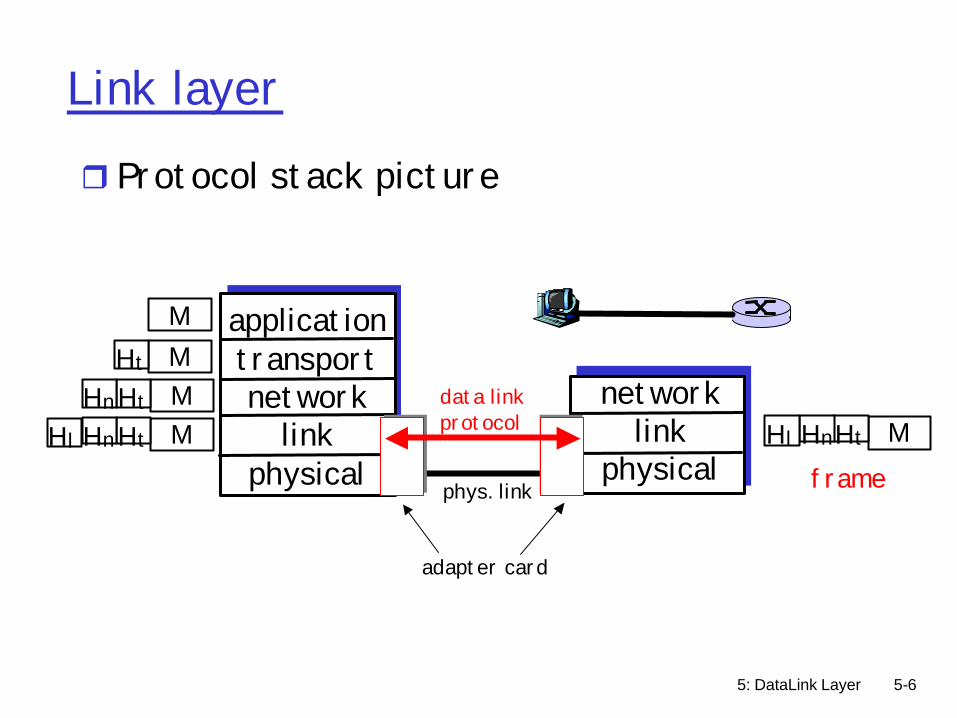
Link layer
r Protocol stack picture
applicationtransportnetwork
linkphysical
networklink
physical
MMMM
Ht
HtHn
HtHnHl MHtHnHl
framephys. link
data linkprotocol
adapter card
5: DataLink Layer 5-7
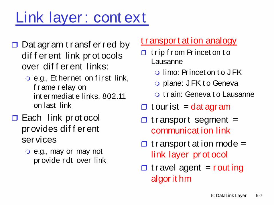
Link layer: contextr Datagram transferred by
different link protocols over different links:m e.g., Ethernet on first link,
frame relay on intermediate links, 802.11 on last link
r Each link protocol provides different servicesm e.g., may or may not
provide rdt over link
transportation analogyr trip from Princeton to
Lausannem limo: Princeton to JFKm plane: JFK to Genevam train: Geneva to Lausanne
r tourist = datagramr transport segment =
communication linkr transportation mode =
link layer protocolr travel agent = routing
algorithm
5: DataLink Layer 5-8
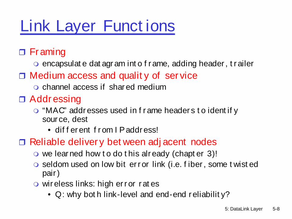
Link Layer Functionsr Framing
m encapsulate datagram into frame, adding header, trailerr Medium access and quality of service
m channel access if shared mediumr Addressing
m “MAC” addresses used in frame headers to identify source, dest
• different from IP address!r Reliable delivery between adjacent nodes
m we learned how to do this already (chapter 3)!m seldom used on low bit error link (i.e. fiber, some twisted
pair)m wireless links: high error rates
• Q: why both link-level and end-end reliability?

5: DataLink Layer 5-9
Link Layer Functions (more)
r Flow Controlm pacing between adjacent sending and receiving nodes
r Error Detectionm errors caused by signal attenuation, noise. m receiver detects presence of errors:
• signals sender for retransmission or drops frame
r Error Correctionm receiver identifies and corrects bit error(s) without
resorting to retransmissionr Securityr Demux to upper protocol

5: DataLink Layer 5-10
Framing
rData encapsulation for transmission over physical link
rData embedded within a link-layer frame before transmission
rData-link header and/or trailer addedr Physical addresses used in frame headers
to identify source and destination (not IP)
5: DataLink Layer 5-11
Fixed length framing
r Length delimitedm Beginning of frame has lengthm Single corrupt length can cause problems
• Must have start of frame character to resynchronize• Resynchronization can fail if start of frame character
is inside packets as well

5: DataLink Layer 5-12
Variable length framing
r Byte stuffingm Special start of frame byte (e.g. 0xFF)m Special escape byte value (e.g. 0xFE)m Values actually in text are replaced (e.g. 0xFF
by 0xFEFF and 0xFE by 0xFEFE)mWorst case – can double the size of frame
r Bit stuffingm Special bit sequence (0x01111110)m 0 bit stuffed after any 11111 sequence
5: DataLink Layer 5-13
Clock-Based Framing
rUsed by SONETr Fixed size frames (810 bytes)r Look for start of frame marker that
appears every 810 bytesrWill eventually sync up
5: DataLink Layer 5-14
Demux to upper protocol
r Protocol type specification interfaces to network layer
rData-link layer can support any number of network layersm Type field in data-link header specifies network
layer of packetm Each data-link layer defines its own protocol
type numbering for network layerm IP is one of many network layers
5: DataLink Layer 5-15
Demux to upper protocol
r http://www.cavebear.com/CaveBear/Ethernet/type.html
rSome Ethernet protocol types– 0800 DOD Internet Protocol (IP) – 0806 Address Resolution Protocol (ARP)– 8037 IPX (Novell Netware) – 80D5 IBM SNA Services– 809B EtherTalk (AppleTalk over Ethernet)
5: DataLink Layer 5-16
Security
rMainly for broadcast data-link layersm Encrypt payload of higher layersmHide IP source/destination from eavesdroppersm Important for wireless LANs especially
• Parking lot attacks• 802.11b and WEP
r If time permits, security will be covered at the end of the course….
5: DataLink Layer 5-17
Flow control
r Pacing between sender and receiverrSender prevented from overrunning
receiverr Ready-To-Send, Clear-To-Send

5: DataLink Layer 5-18
Reliable delivery
r Reliability at the link layerrHandled in a similar manner to transport
protocolsm ARQ, Stop-and-wait, Go-back-N, Selective
RepeatrWhen and why should this be used?
? Rarely done over twisted-pair or fiber optic links
? Usually done over lossy links for performance improvement (versus correctness)
5: DataLink Layer 5-19
Link Layer
r 5.1 Introduction and services
r 5.2 Error detection and correction
r 5.3Multiple access protocols
r 5.4 Link-Layer Addressing
r 5.5 Ethernet and other data link layers
r 5.6 Hubs and switchesr 5.7 PPPr 5.8 Link Virtualization:
ATM

5: DataLink Layer 5-20
Error detection/correction
r Errors caused by signal attenuation, noise. r Receiver detects presence of errorsr Possible actionsm Signal sender for retransmissionm Drops framem Correct bit errors if possible and continue
5: DataLink Layer 5-21
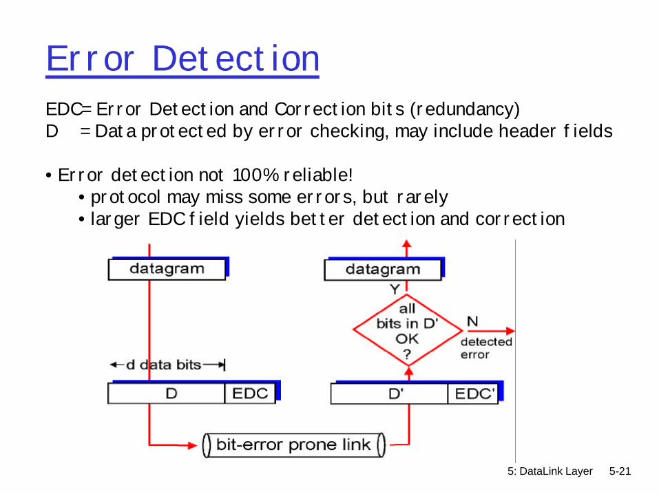
Error DetectionEDC= Error Detection and Correction bits (redundancy)D = Data protected by error checking, may include header fields
• Error detection not 100% reliable!• protocol may miss some errors, but rarely• larger EDC field yields better detection and correction
5: DataLink Layer 5-22
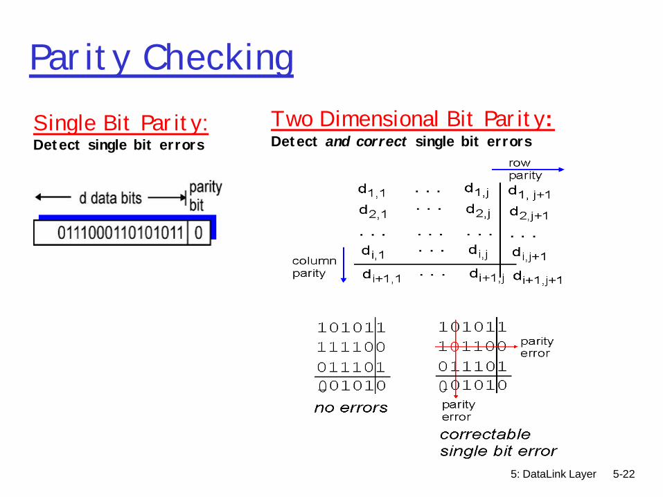
Parity CheckingSingle Bit Parity:Detect single bit errors
Two Dimensional Bit Parity:Detect and correct single bit errors
0 0

5: DataLink Layer 5-23
Internet checksum
Sender:r treat segment contents
as sequence of 16-bit integers
r checksum: addition (1’s complement sum) of segment contents
r sender puts checksum value into UDP checksum field
Receiver:r compute checksum of received
segmentr check if computed checksum
equals checksum field value:m NO - error detectedm YES - no error detected. But
maybe errors nonetheless?More later ….
Goal: detect “errors” (e.g., flipped bits) in transmitted segment (note: used at transport layer only)

5: DataLink Layer 5-24
Cyclic Redundancy Check (CRC)
r Polynomial codem Treat packet bits a coefficients of n-bit polynomialm Choose r+1 bit generator polynomial G
• G well known – chosen in advancem Add r bits to packet so that message is divisible by G
• At receiver, divide payload by generator polynomial• If result not zero, error detected
r Better loss detection properties than checksumsm All single bit errors, all double bit errors, all odd-
numbered errors, burst errors less than rm widely used in practice (ATM, HDCL, now in SCTP)
5: DataLink Layer 5-25
Cyclic Redundancy Check (CRC)
r Calculate code using modulo 2 division of data by generator polynomialm Subtraction equivalent to XORmWeak definition of magnitude
• X >= Y iff position of highest 1 bit of X is the same or greater than the highest 1 bit of Y
r Record remainder after division and send after data
r Result divisible by generator polynomial

5: DataLink Layer 5-26
Cyclic Redundancy Check (CRC)
5: DataLink Layer 5-27
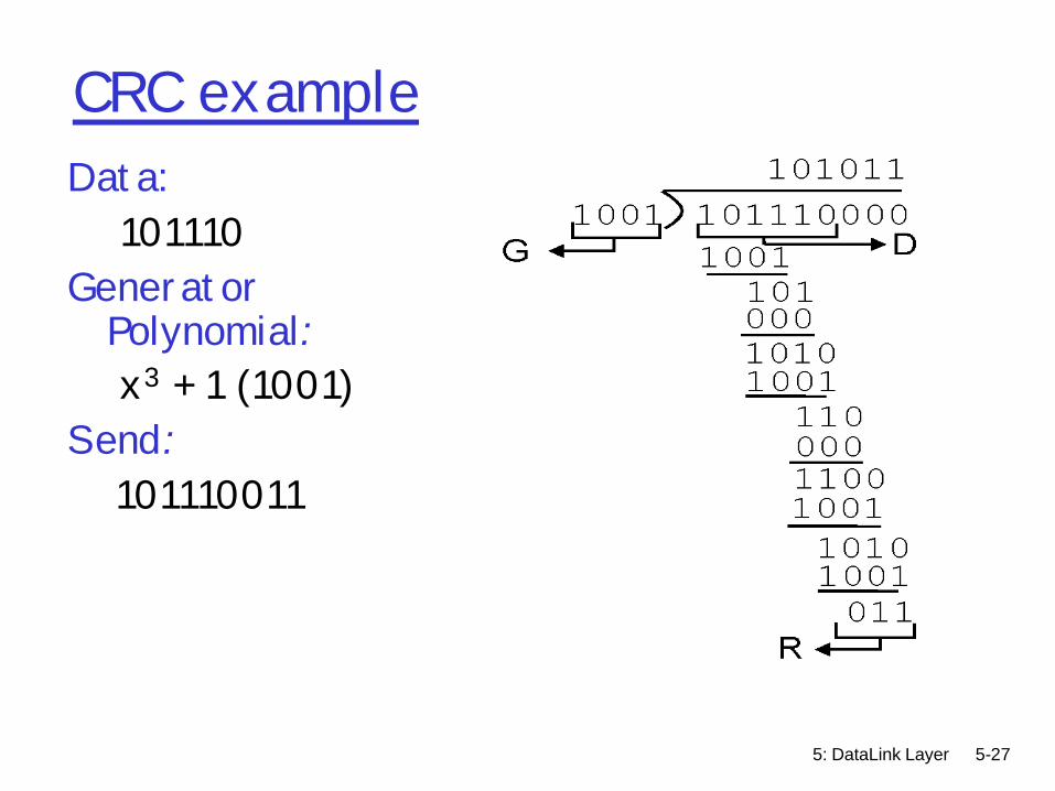
CRC exampleData:
101110Generator
Polynomial:x3 + 1 (1001)
Send:101110011

5: DataLink Layer 5-28
CRC exampleData:
10000Generator
Polynomial:x2 + 1 (101)
Send:1000001
101 1000000101
01000010010101000010010101
101
D
G
R

5: DataLink Layer 5-29
Cyclic Redundancy Check (CRC)
r CRC-16 implementationrShift register and XOR gates
5: DataLink Layer 5-30
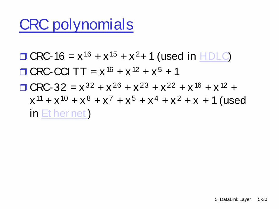
CRC polynomials
r CRC-16 = x16 + x15 + x2+ 1 (used in HDLC) r CRC-CCITT = x16 + x12 + x5 + 1 r CRC-32 = x32 + x26 + x23 + x22 + x16 + x12 +
x11 + x10 + x8 + x7 + x5 + x4 + x2 + x + 1 (used in Ethernet)
5: DataLink Layer 5-31
Forward error correction
r FECm Use error correcting codes to repair lossesm Add redundant information which allows
receiver to correct bit errorsm Suggest looking at information and coding
theory work.

5: DataLink Layer 5-32
Link Layer
r 5.1 Introduction and services
r 5.2 Error detection and correction
r 5.3Multiple access protocols
r 5.4 Link-Layer Addressing
r 5.5 Ethernet and other data link layers
r 5.6 Hubs and switchesr 5.7 PPPr 5.8 Link Virtualization:
ATM
5: DataLink Layer 5-33
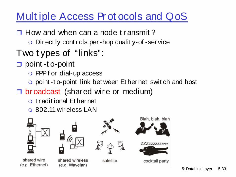
Multiple Access Protocols and QoSr How and when can a node transmit?
m Directly controls per-hop quality-of-service
Two types of “links”:r point-to-point
m PPP for dial-up accessm point-to-point link between Ethernet switch and host
r broadcast (shared wire or medium)m traditional Ethernetm 802.11 wireless LAN
5: DataLink Layer 5-34
Media access problemr Point-to-point link and switched media no problemr Broadcast links?
m Network arbitrationm Give everyone a fixed time/freq slot?
• Ok for fixed bandwidth (e.g., voice)• What if traffic is bursty?
m Centralized arbiter• Ex: cell phone base station• Single point of failure
m Distributed arbitration• Aloha/Ethernet
m Humans use multiple access protocols all the time
5: DataLink Layer 5-35
Multiple access protocolsr single shared communication channel r two or more simultaneous transmissions by nodes:
interference m only one node can send successfully at a time
r multiple access protocol:m distributed algorithm that determines how stations share
channel, i.e., determine when station can transmitm communication about channel sharing uses channel itself! m what to look for in multiple access protocols:
• synchronous or asynchronous • information needed about other stations • robustness (e.g., to channel errors) • performance
5: DataLink Layer 5-36
Ideal Mulitple Access Protocol
Broadcast channel of rate R bps1. When one node wants to transmit, it can send at
rate R.2. When M nodes want to transmit, each can send at
average rate R/M3. Fully decentralized:
m no special node to coordinate transmissionsm no synchronization of clocks, slots
4. Simple
5: DataLink Layer 5-37
MAC Protocols: a taxonomyThree broad classes:r Channel Partitioning
m divide channel into smaller “pieces” (time slots, frequency, code)
m allocate piece to node for exclusive user Random Access
m channel not divided, allow collisionsm “recover” from collisions
r “Taking turns”m tightly coordinate shared access to avoid collisionsm Nodes take turns, but nodes with more to send can take
longer turns
Goal: efficient, fair, simple, decentralized
5: DataLink Layer 5-38
Channel Partitioning MAC protocols: TDMA
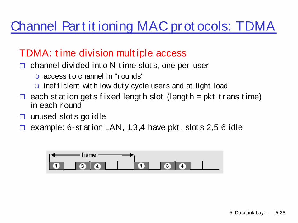
TDMA: time division multiple accessr channel divided into N time slots, one per user
m access to channel in "rounds" m inefficient with low duty cycle users and at light load
r each station gets fixed length slot (length = pkt trans time) in each round
r unused slots go idle r example: 6-station LAN, 1,3,4 have pkt, slots 2,5,6 idle
5: DataLink Layer 5-39
Channel Partitioning MAC protocols: FDMA
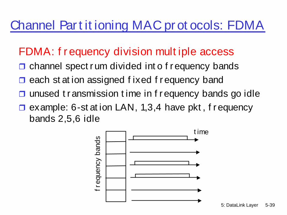
FDMA: frequency division multiple accessr channel spectrum divided into frequency bandsr each station assigned fixed frequency bandr unused transmission time in frequency bands go idle r example: 6-station LAN, 1,3,4 have pkt, frequency
bands 2,5,6 idle
freq
uenc
y ba
nds
time

5: DataLink Layer 5-40
Channel Partitioning MAC protocols
CDMA (Code Division Multiple Access)r unique “code” assigned to each user; ie, code set partitioningr used mostly in wireless broadcast channels (cellular,
satellite,etc)r each user has own “chipping” sequence (ie, code) to encode
datar encoded signal = (original data) X (chipping sequence)r decoding: inner-product of encoded signal and chipping
sequencer allows multiple users to “coexist” and transmit
simultaneously with minimal interference (if codes are “orthogonal”)

5: DataLink Layer 5-41
Channel Partitioning MAC protocolsr CDMA Encode/Decode
5: DataLink Layer 5-42
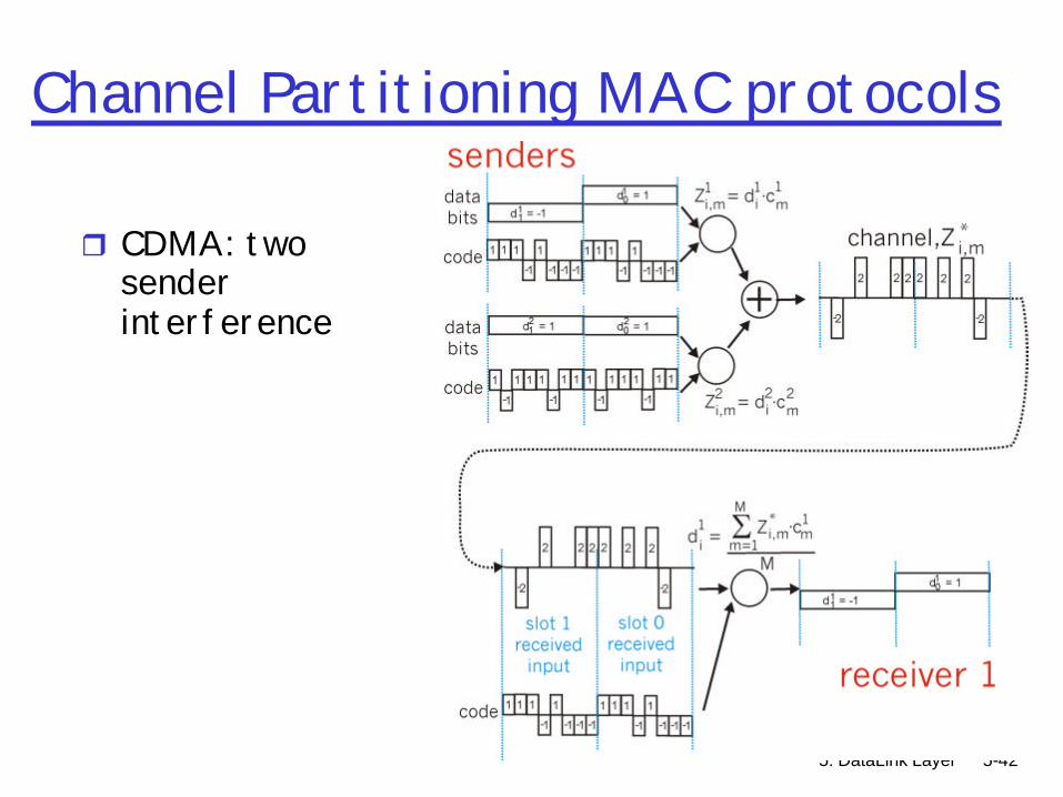
Channel Partitioning MAC protocols
r CDMA: two sender interference
5: DataLink Layer 5-43
Random Access Protocols
r When node has packet to sendm transmit at full channel data rate R.m no a priori coordination among nodes
r two or more transmitting nodes ? “collision”,r To avoid deterministic collisions: randomize
m random access MAC protocol specifies: • how to detect collisions• how to recover from collisions (e.g., via delayed
retransmissions)• “Asynchronous” TDMA
r Examples of random access MAC protocols:m slotted ALOHAm ALOHAm CSMA, CSMA/CD, CSMA/CA
5: DataLink Layer 5-44
Slotted ALOHA
Assumptionsr all frames same sizer time is divided into
equal size slots, time to transmit 1 frame
r nodes start to transmit frames only at beginning of slots
r nodes are synchronizedr if 2 or more nodes
transmit in slot, all nodes detect collision
Operationr when node obtains fresh
frame, it transmits in next slot
r no collision, node can send new frame in next slot
r if collision, node retransmits frame in each subsequent slot with prob. p until success

5: DataLink Layer 5-45
Slotted ALOHA
Prosr single active node can
continuously transmit at full rate of channel
r highly decentralized: only slots in nodes need to be in sync
r simple
Consr collisions, wasting slotsr idle slotsr nodes may be able to
detect collision in less than time to transmit packet
r clock synchronization
5: DataLink Layer 5-46
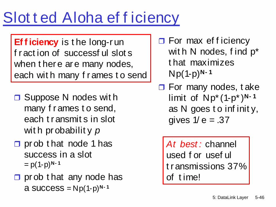
Slotted Aloha efficiency
r Suppose N nodes with many frames to send, each transmits in slot with probability p
r prob that node 1 has success in a slot= p(1-p)N-1
r prob that any node has a success = Np(1-p)N-1
r For max efficiency with N nodes, find p* that maximizes Np(1-p)N-1
r For many nodes, take limit of Np*(1-p*)N-1
as N goes to infinity, gives 1/e = .37
Efficiency is the long-run fraction of successful slots when there are many nodes, each with many frames to send
At best: channelused for useful transmissions 37%of time!
5: DataLink Layer 5-47
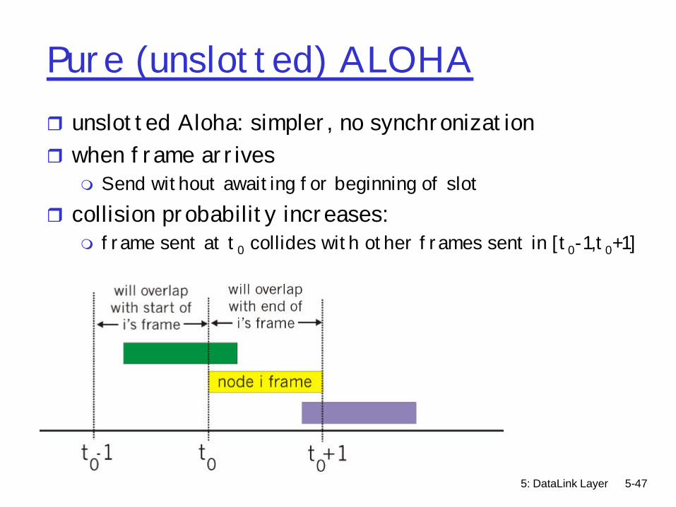
Pure (unslotted) ALOHAr unslotted Aloha: simpler, no synchronizationr when frame arrives
m Send without awaiting for beginning of slotr collision probability increases:
m frame sent at t0 collides with other frames sent in [t0-1,t0+1]

5: DataLink Layer 5-48
Pure Aloha efficiency
P(success by given node) = P(node transmits) .P(no other node transmits in [p0-1,p0] .P(no other node transmits in [p0,p0+1]
= p . (1-p)(N-1) . (1-p) (N-1)
P(success by any of N nodes) = N p . (1-p) (N-1). (1-p) (N-1)
… choosing optimum p as n -> infty ... = 1/(2e) = .18
S =
thr
ough
put
= “g
oodp
ut”
(suc
cess
rat
e)
G = offered load = Np0.5 1.0 1.5 2.0
0.1
0.2
0.3
0.4
Pure Aloha
Slotted Aloha
protocol constrainseffective channelthroughput!

5: DataLink Layer 5-49
CSMA (Carrier Sense Multiple Access)
CSMA: listen before transmit:If channel sensed idle: transmit entire framer If channel sensed busy, defer transmission m Persistent CSMA: retry immediately with
probability p when channel becomes idlemNon-persistent CSMA: retry after random interval
r Human analogy: don’t interrupt others!

5: DataLink Layer 5-50
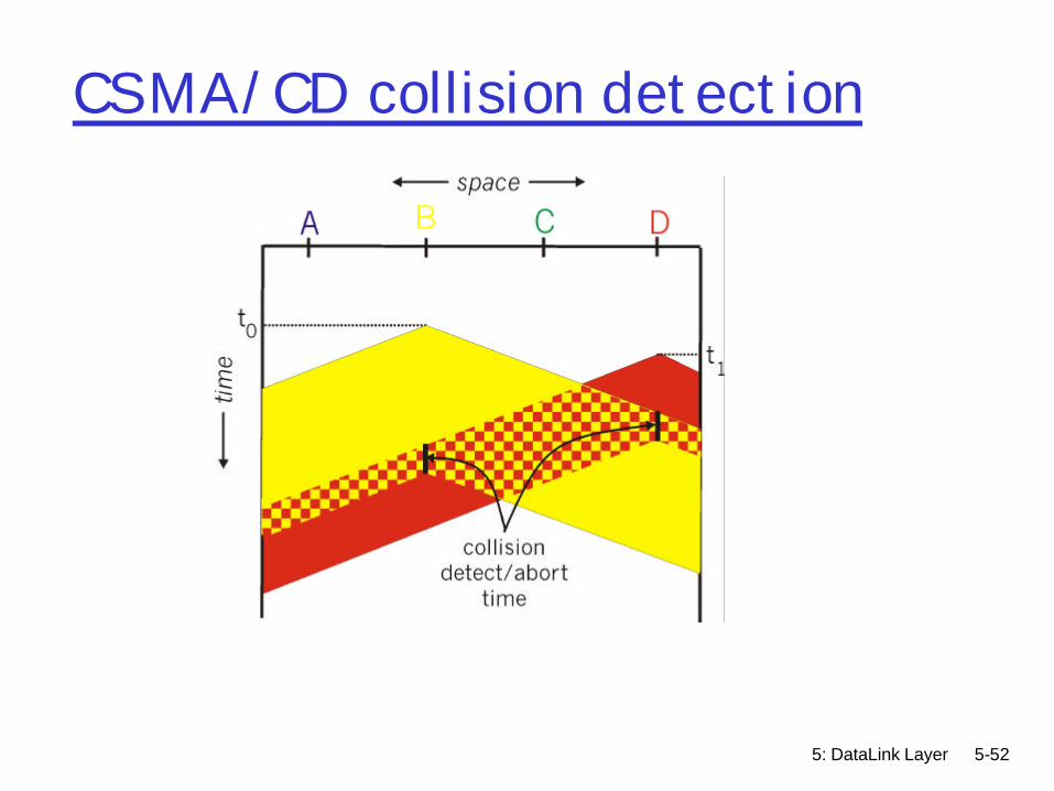
CSMA collisions
collisions can still occur:propagation delay means two nodes may not heareach other’s transmission
collision:entire packet transmission time wasted
spatial layout of nodes
note:role of distance & propagation delay in determining collision probability
5: DataLink Layer 5-51
CSMA/CD (Collision Detection)CSMA/CD: carrier sensing, deferral as in CSMAm collisions detected within short timem colliding transmissions aborted, reducing channel
wastage r collision detection:m easy in wired LANs: measure signal strengths,
compare transmitted, received signals• Collisions detected within short time• Abort transmission as soon as collision detected to reduce
channel waste
r human analogy: the polite conversationalist
5: DataLink Layer 5-52
CSMA/CD collision detection
5: DataLink Layer 5-53
CSMA/CD problems
r Can CSMA/CD work over wireless LANsm Collision detection difficult in wireless LANs:
receiver shut off while transmittingm Hidden terminal problem

5: DataLink Layer 5-54
Hidden Terminal effect
rA, C cannot hear each otherm obstacles, signal attenuationmNeither A or C can tell if they collide at B
5: DataLink Layer 5-55
CSMA/CAr Use base CSMAr Add acknowledgements
m Receiver acknowledges receipt of datam Avoids hidden terminal problem
r Avoid collisions explicitly via channel reservationm Sender sends “request-to-send” (RTS) messages
• Transmitted without reservation using CSMA with ACKsm Receiver sends “clear-to-send” (CTS) messages
• Transmitted without reservation using CSMA with ACKsm Sender sends data packet using reservation
• Explicitly indicates length of so others know how long to back offr Used in 802.11 wireless LAN networks

5: DataLink Layer 5-56
“Taking Turns” MAC protocols
Recall, channel partitioning MAC protocols:m share channel efficiently and fairly at high loadm inefficient at low load: delay in channel access,
1/N bandwidth allocated even if only 1 active node!
Random access MAC protocolsm efficient at low load: single node can fully
utilize channelm high load: collision overhead
“taking turns” protocolslook for best of both worlds!
5: DataLink Layer 5-57
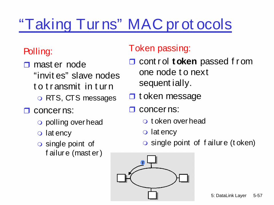
“Taking Turns” MAC protocolsPolling:r master node
“invites” slave nodes to transmit in turnm RTS, CTS messages
r concerns:m polling overhead m latencym single point of
failure (master)
Token passing:r control token passed from
one node to next sequentially.
r token messager concerns:
m token overhead m latencym single point of failure (token)

5: DataLink Layer 5-58
Taking-turns protocolsDistributed Polling:r time divided into slotsr begins with N short reservation slots
m reservation slot time equal to channel end-end propagation delay
m station with message to send posts reservationm reservation seen by all stations
r after reservation slots, message transmissions ordered by known priority

5: DataLink Layer 5-59
Summary of MAC protocols
rWhat do you do with a shared media?m Channel Partitioning, by time, frequency or code
• Time Division, Frequency Divisionm Random partitioning (dynamic),
• ALOHA, S-ALOHA, CSMA, CSMA/CD• carrier sensing: easy in some technologies (wire), hard
in others (wireless)• CSMA/CD used in Ethernet• CSMA/CA used in 802.11
m Taking Turns• polling from a central site, token passing
5: DataLink Layer 5-60
Link Layer
r 5.1 Introduction and services
r 5.2 Error detection and correction
r 5.3Multiple access protocols
r 5.4 Link-Layer Addressing
r 5.5 Ethernet and other data link layers
r 5.6 Hubs and switchesr 5.7 PPPr 5.8 Link Virtualization:
ATM
5: DataLink Layer 5-61
MAC Addresses
r 32-bit IP address: m network-layer addressm used to route between networks to get datagram to
destination IP subnet r MAC (or LAN or physical or Ethernet) address:
m used to get frame from one interface to another physically-connected interface (same network)
m 48 bit MAC address (for most LANs) burned in the adapter ROM
• ifconfig –a• arp -a

5: DataLink Layer 5-62
Physical addressing
rWhy have separate IP and hardware addresses?m Assign adapters an IP address
• Hardware only works for IP (no IPX, DECNET)• Must be reconfigured when moved
m Use hardware address as network address• Need standardized fixed length hardware address• No route aggregation

5: DataLink Layer 5-63
LAN Addresses and ARPEach adapter on LAN has unique LAN address
Broadcast address =FF-FF-FF-FF-FF-FF
= adapter
1A-2F-BB-76-09-AD
58-23-D7-FA-20-B0
0C-C4-11-6F-E3-98
71-65-F7-2B-08-53
LAN(wired orwireless)
5: DataLink Layer 5-64
LAN Address (more)
r MAC address allocation administered by IEEEm manufacturer buys portion of MAC address space (to
assure uniqueness)r Analogy:
(a) MAC address: like Social Security Number(b) IP address: like postal address
r MAC flat address ? portability m can move LAN card from one LAN to another
r IP hierarchical address NOT portablem depends on IP subnet to which node is attached

5: DataLink Layer 5-65
ARP: Address Resolution Protocol
r Each IP node (Host, Router) on LAN has ARP table
r ARP Table: IP/MAC address mappings for some LAN nodes
< IP address; MAC address; TTL>m TTL (Time To Live): time
after which address mapping will be forgotten (typically 20 min)
Question: how to determineMAC address of Bknowing B’s IP address?
1A-2F-BB-76-09-AD
58-23-D7-FA-20-B0
0C-C4-11-6F-E3-98
71-65-F7-2B-08-53
LAN
237.196.7.23
237.196.7.78
237.196.7.14
237.196.7.88

5: DataLink Layer 5-66
ARP protocol: Same LAN (network)
r A knows B’s IP address and wants to send datagram to B, and B’s MAC address not in A’s ARP table.
r A broadcasts ARP query packet, containing B's IP address m Dest MAC address =
FF-FF-FF-FF-FF-FFm all machines on LAN
receive ARP queryr B receives ARP packet,
replies to A with its (B's) MAC addressm frame sent to A’s MAC
address (unicast)
r A caches (saves) IP-to-MAC address pair in its ARP table until information becomes old (times out) m soft state: information
that times out (goes away) unless refreshed
r ARP is “plug-and-play”:m nodes create their ARP
tables without intervention from net administrator
5: DataLink Layer 5-67
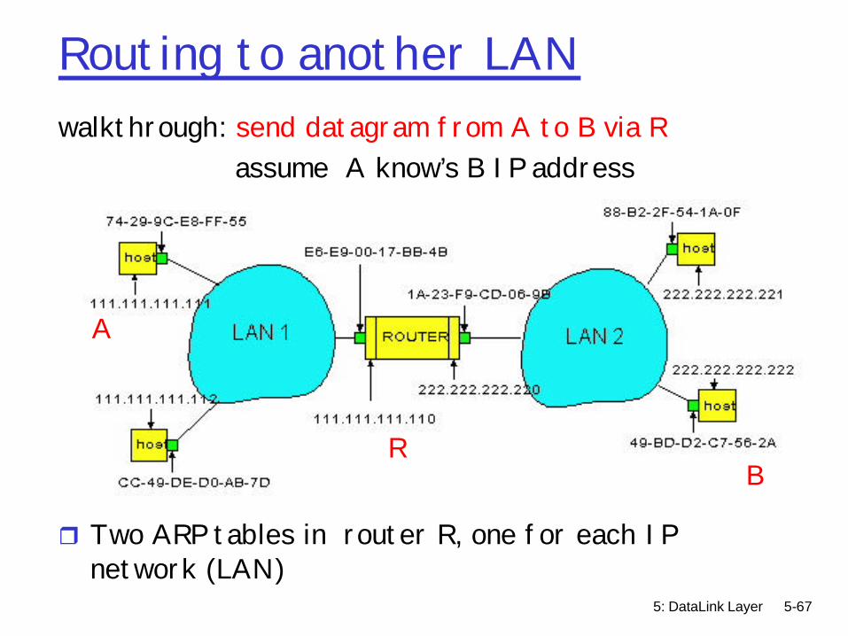
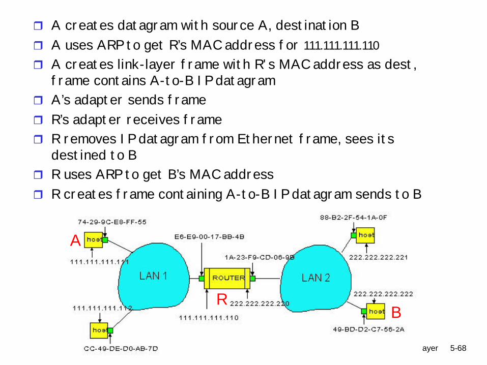
Routing to another LANwalkthrough: send datagram from A to B via R
assume A know’s B IP address
r Two ARP tables in router R, one for each IP network (LAN)
A
RB
5: DataLink Layer 5-68
r A creates datagram with source A, destination B r A uses ARP to get R’s MAC address for 111.111.111.110r A creates link-layer frame with R's MAC address as dest,
frame contains A-to-B IP datagramr A’s adapter sends frame r R’s adapter receives frame r R removes IP datagram from Ethernet frame, sees its
destined to Br R uses ARP to get B’s MAC address r R creates frame containing A-to-B IP datagram sends to B
A
RB

5: DataLink Layer 5-69
RARP, BOOTP, DHCPARP: Given an IP address, return a hardware addressRARP: Given a hardware address, give me the IP
addressDHCP, BOOTP: Similar to RARPHosts (host portion):r hard-coded by system admin in a filer DHCP: Dynamic Host Configuration Protocol:
dynamically get address: “plug-and-play”m host broadcasts “DHCP discover” msgm DHCP server responds with “DHCP offer” msgm host requests IP address: “DHCP request” msgm DHCP server sends address: “DHCP ack” msg
5: DataLink Layer 5-70
Link Layer
r 5.1 Introduction and services
r 5.2 Error detection and correction
r 5.3Multiple access protocols
r 5.4 Link-Layer Addressing
r 5.5 Ethernet and other data link layers
r 5.6 Hubs and switchesr 5.7 PPPr 5.8 Link Virtualization:
ATM
5: DataLink Layer 5-71
Specific data-link layers
r Specific data-link layersm Ethernet (802.3)m Token Ring (802.5)m WiFi (802.11)m X.25m Frame relaym Special link layers covered later (PPP, ATM)
5: DataLink Layer 5-72
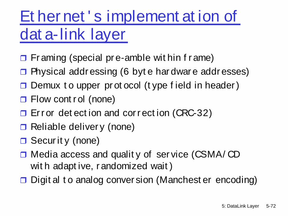
Ethernet's implementation of data-link layerr Framing (special pre-amble within frame)r Physical addressing (6 byte hardware addresses)r Demux to upper protocol (type field in header)r Flow control (none)r Error detection and correction (CRC-32)r Reliable delivery (none)r Security (none)r Media access and quality of service (CSMA/CD
with adaptive, randomized wait)r Digital to analog conversion (Manchester encoding)

5: DataLink Layer 5-73
Ethernet“dominant” wired LAN technology:
m First practical local area network, built at Xerox PARC in 70’s
m cheap: $3 for 100Mbs NICm first widely used LAN technologym Simpler, cheaper than token LANs and ATMm Kept up with speed race: 10 Mbps – 10 Gbps
Metcalfe’s Ethernetsketch

5: DataLink Layer 5-74
Ethernet Frame StructureSending adapter encapsulates IP datagram (or other
network layer protocol packet) in Ethernet frame
Preamble:r 7 bytes with pattern 10101010 followed by one
byte with pattern 10101011m used to synchronize receiver, sender clock rates
r Ethernet II frame standard, some others….m Original circa 1970 Xerox PARCm IEEE 802.3 LLC framem IEEE 802.3 SNAP framem Novell Proprietarym Not all compatible with each other

5: DataLink Layer 5-75
Ethernet Frame Structure (more)r Addresses: 6 bytes
m Globally unique, allocated to manufacturersm if adapter receives frame with matching destination address, or
with broadcast address (eg ARP packet), it passes data in frame to net-layer protocol
m otherwise, adapter discards framer Type: indicates the higher layer protocol
m mostly IP but others include Novell IPX and AppleTalkr Data – 46 to 1500 bytesr CRC: 4 bytes
m checked at receiver, if error is detected, frame is droppedm CRC-32
• (x32+x26+x23+x22+x16+x12+x11+x10+x8+x7+x5+x4+x2+x+1)
5: DataLink Layer 5-76
Unreliable, connectionless service
r Connectionless: No handshaking between sending and receiving adapter.
r Unreliable: receiving adapter doesn’t send acks or nacks to sending adapterm stream of datagrams passed to network layer can have
gapsm gaps will be filled if app is using TCPm otherwise, app will see the gaps

5: DataLink Layer 5-77
Ethernet uses CSMA/CD
r No slotsr adapter doesn’t transmit
if it senses that some other adapter is transmitting, that is, carrier sense
r transmitting adapter aborts when it senses that another adapter is transmitting, that is, collision detection
r Before attempting a retransmission, adapter waits a random time, that is, random access
5: DataLink Layer 5-78
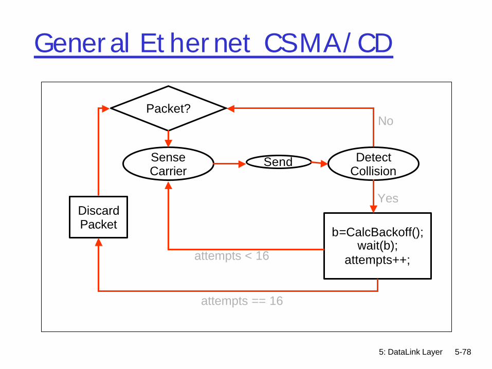
General Ethernet CSMA/CD
Packet?
Sense Carrier
Discard Packet
Send Detect Collision
b=CalcBackoff(); wait(b);
attempts++;
No
Yes
attempts < 16
attempts == 16
5: DataLink Layer 5-79
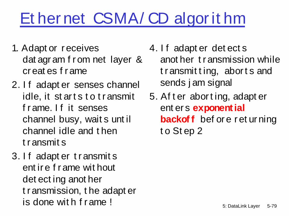
Ethernet CSMA/CD algorithm1. Adaptor receives
datagram from net layer & creates frame
2. If adapter senses channel idle, it starts to transmit frame. If it senses channel busy, waits until channel idle and then transmits
3. If adapter transmits entire frame without detecting another transmission, the adapter is done with frame !
4. If adapter detects another transmission while transmitting, aborts and sends jam signal
5. After aborting, adapter enters exponential backoff before returning to Step 2

5: DataLink Layer 5-80
Ethernet’s CSMA/CD (more)Jam Signal: make sure all other transmitters are aware of
collision; 48 bits (more later)Bit time: .1 microsec for 10 Mbps Ethernet ;
for K=1023, wait time is about 50 msecExponential backoff calculation: If deterministic delay after
collision, collision will occur again in lockstepm If random delay with fixed mean
• Few senders à needless waiting• Too many senders à too many collisions
m Exponentially increasing random delay• Infer senders from # of collisions• More senders à increase wait time
5: DataLink Layer 5-81
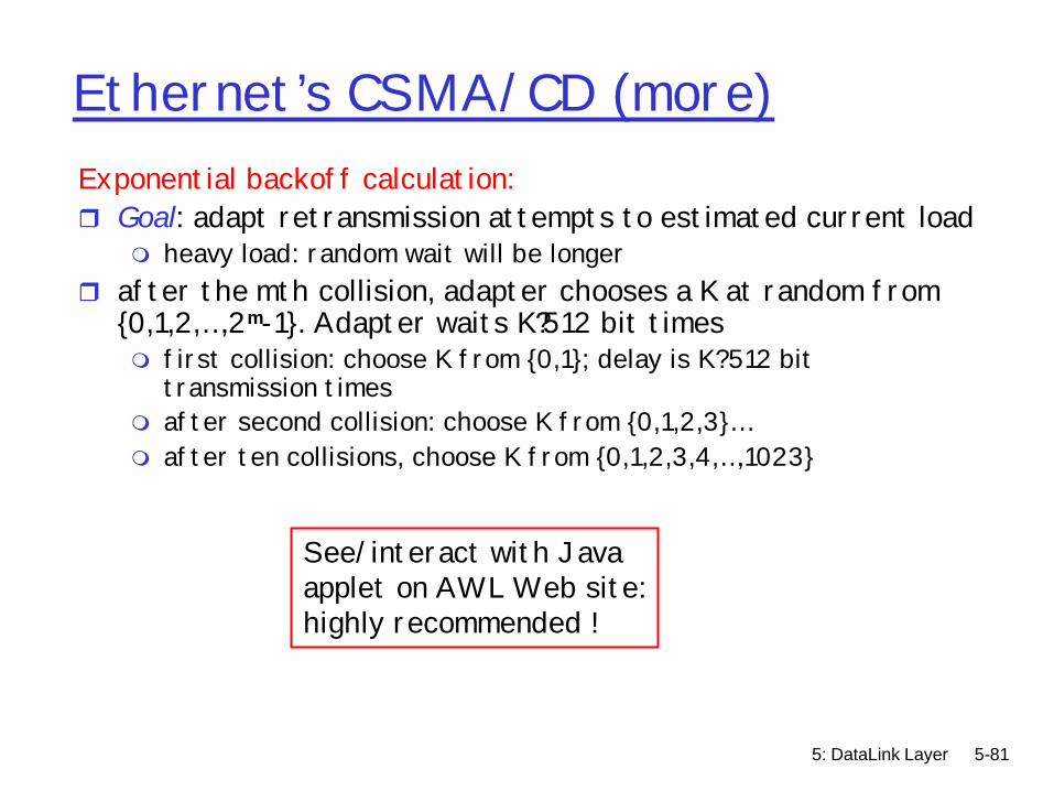
Ethernet’s CSMA/CD (more)Exponential backoff calculation:r Goal: adapt retransmission attempts to estimated current load
m heavy load: random wait will be longerr after the mth collision, adapter chooses a K at random from
{0,1,2,…,2m-1}. Adapter waits K?512 bit timesm first collision: choose K from {0,1}; delay is K?512 bit
transmission timesm after second collision: choose K from {0,1,2,3}…m after ten collisions, choose K from {0,1,2,3,4,…,1023}
See/interact with Javaapplet on AWL Web site:highly recommended !

5: DataLink Layer 5-82
Ethernet: uses CSMA/CDif packetthen {
A: sense channelif idlethen {
transmit and monitor the channel; if detect another transmission then {
abort and send jam signal; update # collisions; delay as required by exponential backoff algorithm; goto A}
else {done with the frame; set collisions to zero}}
else {wait until ongoing transmission is over and goto A}}

5: DataLink Layer 5-83
Ethernet CSMA/CD and Packet Size
rWhat if two people sent really small packetsmHow do you find
collision?mMust have a
minimum packet size
5: DataLink Layer 5-84
Ethernet Collision Detect & Packet SizerMin packet length > 2x max prop delaym If A, B are at opposite sides of link, and B
starts one link prop delay after Ar Jam signalm Jam network for after collision, then stop
sendingm Ensures that everyone notices collision

5: DataLink Layer 5-85
Propagation delay & packet size
r Propagation delay determines min. packet size to prevent undetected collisions
rModern 10Mb EthernetmMinimum packet size calculation
• 500m maximum segment length• Can add repeaters up to a maximum 5 segments
(2500m)• c in cable = 60% * c in vacuum = 1.8 x 10^8 m/s• ~ 12.5us one-way delay• Add repeater and tranceiver delay• To be safe IEEE specifies a 512 “bit-time” slot for
Ethernet = 51.2us • 512 bits = 64 bytes (data payload = 46 bytes)

5: DataLink Layer 5-86
Minimum packet size
rWhat about scaling? 100Mbit, 1Gbit...rMake network smaller?m Solution for 100BaseT
rMake min pkt size larger?m 512bits @ 1Gbps = 512nsm 512ns * 1.8 * 10^8 = 92metersm Gigabit ethernet uses collision extension for
small pkts
5: DataLink Layer 5-87
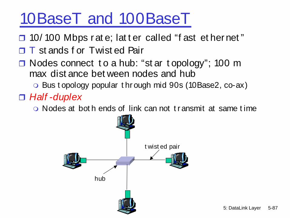
10BaseT and 100BaseTr 10/100 Mbps rate; latter called “fast ethernet”r T stands for Twisted Pairr Nodes connect to a hub: “star topology”; 100 m
max distance between nodes and hubm Bus topology popular through mid 90s (10Base2, co-ax)
r Half-duplexm Nodes at both ends of link can not transmit at same time
twisted pair
hub
5: DataLink Layer 5-88
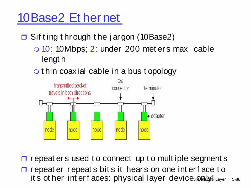
10Base2 Ethernetr Sifting through the jargon (10Base2)m 10: 10Mbps; 2: under 200 meters max cable
lengthm thin coaxial cable in a bus topology
r repeaters used to connect up to multiple segmentsr repeater repeats bits it hears on one interface to
its other interfaces: physical layer device only!
5: DataLink Layer 5-89
Gbit Ethernet
r uses standard Ethernet frame formatr allows for point-to-point links and shared
broadcast channelsr in shared mode, CSMA/CD is used; short distances
between nodes required for efficiencyr Full-Duplex at 1 Gbps for point-to-point links
m Nodes can transmit and receive at 1Gbps simultaneouslyr 10 Gbps now !

5: DataLink Layer 5-90
Ethernet Problems
r Ethernet unstable at high loadsm Peak utilization = 1/e = 37%
r Peak throughput worse withmMore hosts – more collisions needed to identify
single senderm Smaller packet sizes – more frequent
arbitrationm Longer links – collisions take longer to observe,
more wasted bandwidth

5: DataLink Layer 5-91
Token Rings
r Packets broadcast around ringrToken “right to send” rotates around ringm Fair, real-time bandwidth allocation
• Every host holds token for limited time• Higher latency when only one sender
mHigher bandwidth• Point to point links electrically simpler than bus
5: DataLink Layer 5-92
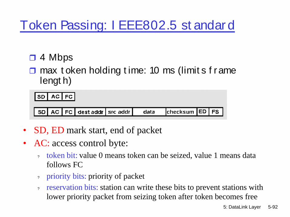
Token Passing: IEEE802.5 standard
r 4 Mbps r max token holding time: 10 ms (limits frame
length)
• SD, ED mark start, end of packet • AC: access control byte:
? token bit: value 0 means token can be seized, value 1 means data follows FC
? priority bits: priority of packet ? reservation bits: station can write these bits to prevent stations with
lower priority packet from seizing token after token becomes free

5: DataLink Layer 5-93
Why Did Ethernet Win?
r Better failure modesm Token rings – network unusablem Ethernet – node detached
r Good performance in common caser Volume à lower cost à higher volume ….r Adaptable
m To higher bandwidths (vs. FDDI)m To switching (vs. ATM)
r Completely distributed, easy to maintain/administer
r Easy incremental deploymentr Cheap cabling, etc
5: DataLink Layer 5-94
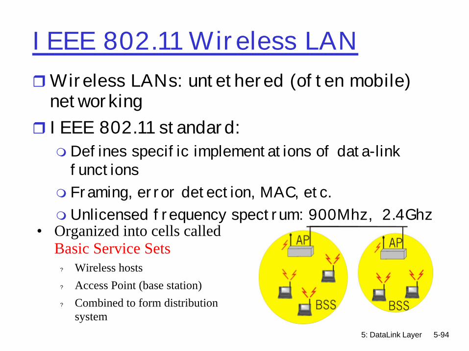
IEEE 802.11 Wireless LANrWireless LANs: untethered (often mobile)
networkingr IEEE 802.11 standard:m Defines specific implementations of data-link
functionsm Framing, error detection, MAC, etc.m Unlicensed frequency spectrum: 900Mhz, 2.4Ghz
• Organized into cells called Basic Service Sets
? Wireless hosts? Access Point (base station)? Combined to form distribution
system
5: DataLink Layer 5-95
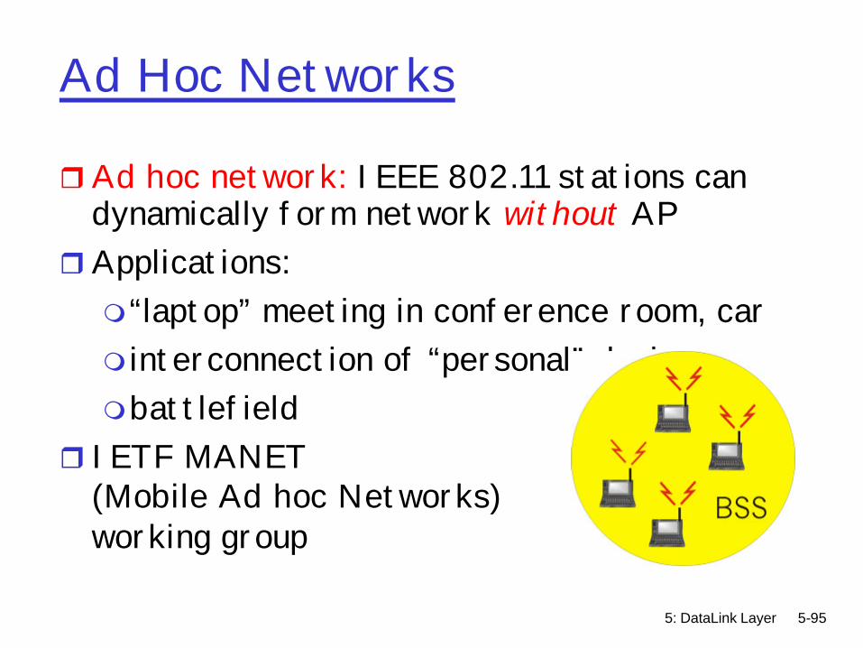
Ad Hoc Networks
rAd hoc network: IEEE 802.11 stations can dynamically form network without AP
rApplications:m“laptop” meeting in conference room, carm interconnection of “personal” devicesmbattlefield
r IETF MANET (Mobile Ad hoc Networks) working group

5: DataLink Layer 5-96
IEEE 802.11 MAC
r Allows for several modesm CSMA (with explicit ACK to indicate collision)m CSMA/CA: reservationsm Polling from AP
5: DataLink Layer 5-97
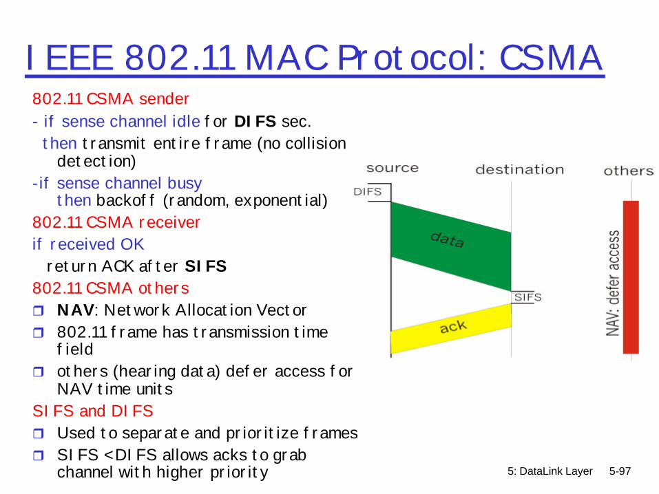
IEEE 802.11 MAC Protocol: CSMA802.11 CSMA sender- if sense channel idle for DIFS sec.
then transmit entire frame (no collision detection)
-if sense channel busy then backoff (random, exponential)
802.11 CSMA receiverif received OK
return ACK after SIFS802.11 CSMA othersr NAV: Network Allocation Vectorr 802.11 frame has transmission time
fieldr others (hearing data) defer access for
NAV time unitsSIFS and DIFSr Used to separate and prioritize framesr SIFS < DIFS allows acks to grab
channel with higher priority

5: DataLink Layer 5-98
IEEE 802.11 MAC Protocol CSMA/CAr Same as previous mode but with explicit channel reservation
m Send short reservation messages via CSMA to reserve channel• Sender RTS (request to send), Receiver CTS (clear to send)• CTS notifies all hidden stations of sender's reservation• Short messages so that collision less likely and of short duration
m Send data unobstructed on reserved channel• End result similar to CSMA/CD

5: DataLink Layer 5-99
X.25 and Frame Relay
Like ATM:rwide area network technologiesr virtual circuit oriented r origins in telephony worldrNot really a link layer but....
m Viewed as link layers by IP protocolm Used mostly to carry IP datagrams between IP
routersr Going the way of the dinosaurs....
5: DataLink Layer 5-100
X.25
r X.25 builds VC between source and destination for each user connection
r Per-hop control along pathm error control (with retransmissions) on each hop using
LAP-B• variant of the HDLC protocol• developed when bit error rates over long-haul copper
links were orders of magnitude higher m per-hop flow control using credits
• congestion arising at intermediate node propagates to previous node on path
• back to source via back pressure

5: DataLink Layer 5-101
IP versus X.25
rX.25: reliable in-sequence end-end delivery from end-to-endm “intelligence in the network”m built for dumb terminals accessing mainframes
rIP: unreliable, out-of-sequence end-end deliverym “intelligence in the endpoints”
r2000m gigabit routers: limited processing possiblem CPU capacity at end-hostsm IP wins
5: DataLink Layer 5-102
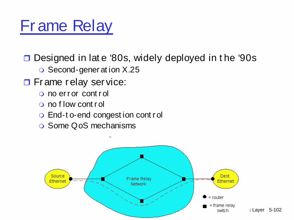
Frame Relay
r Designed in late ‘80s, widely deployed in the ‘90sm Second-generation X.25
r Frame relay service:m no error controlm no flow controlm End-to-end congestion controlm Some QoS mechanisms
5: DataLink Layer 5-103
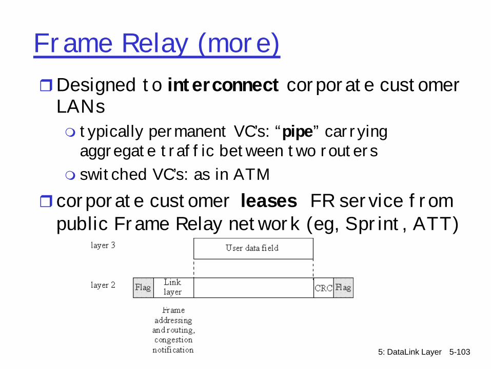
Frame Relay (more)rDesigned to interconnect corporate customer
LANsm typically permanent VC’s: “pipe” carrying
aggregate traffic between two routers m switched VC’s: as in ATM
rcorporate customer leases FR service from public Frame Relay network (eg, Sprint, ATT)
5: DataLink Layer 5-104
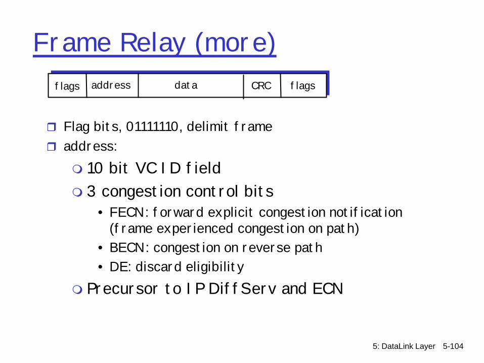
Frame Relay (more)
r Flag bits, 01111110, delimit framer address:
m 10 bit VC ID fieldm 3 congestion control bits
• FECN: forward explicit congestion notification (frame experienced congestion on path)
• BECN: congestion on reverse path• DE: discard eligibility
m Precursor to IP DiffServ and ECN
addressflags data CRC flags
5: DataLink Layer 5-105
Frame Relay -VC Rate Controlr Committed Information Rate (CIR)
m defined, “guaranteed” for each VCm negotiated at VC set up timem customer pays based on CIR
r DE bit: Discard Eligibility bitm Edge FR switch measures traffic rate for each VC; marks DE
bitm DE = 0: high priority, rate compliant frame; deliver at “all
costs”m DE = 1: low priority, eligible for discard when congestionm Precursor to IP DiffServm Can be used to support higher layer QoS mechanisms
5: DataLink Layer 5-106
Link Layer
r 5.1 Introduction and services
r 5.2 Error detection and correction
r 5.3Multiple access protocols
r 5.4 Link-Layer Addressing
r 5.5 Ethernet and other data link layers
r 5.6 Interconnections: Hubs and switches
r 5.7 PPPr 5.8 Link Virtualization:
ATM
5: DataLink Layer 5-107
Link-layer devices
Q: Why not just one big LAN? r Limited amount of supportable traffic: on
single LAN, all stations must share bandwidth
r limited length: 802.3 specifies maximum cable length
r large “collision domain” (can collide with many stations)
r limited number of stations: 802.5 have token passing delays at each station

5: DataLink Layer 5-108
HubsHubs are essentially physical-layer, multi-port repeaters:
m bits coming from one link go out all other linksm at the same ratem no frame bufferingm no CSMA/CD at hub: adapters detect collisionsm provides net management functionality
twisted pair
hub

5: DataLink Layer 5-109
Hubs (more)
rHubs do not isolate collision domains: node may collide with any node residing at any segment in LAN
rHub Advantages:m simple, inexpensive devicem extends maximum distance between node pairsmMulti-tier provides graceful degradation:
portions of the LAN continue to operate if one hub malfunctions
5: DataLink Layer 5-110
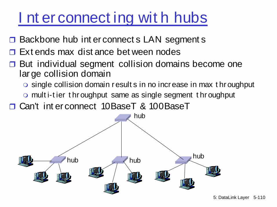
Interconnecting with hubsr Backbone hub interconnects LAN segmentsr Extends max distance between nodesr But individual segment collision domains become one
large collision domainm single collision domain results in no increase in max throughputm multi-tier throughput same as single segment throughput
r Can’t interconnect 10BaseT & 100BaseT
hub hub hub
hub
5: DataLink Layer 5-111
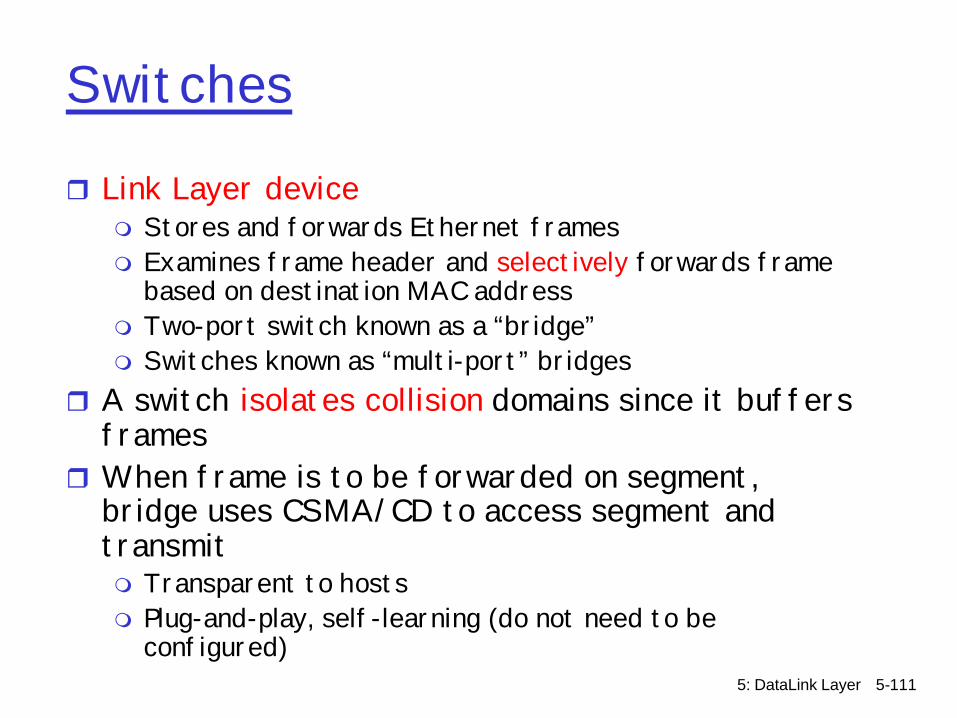
Switches
r Link Layer devicem Stores and forwards Ethernet framesm Examines frame header and selectively forwards frame
based on destination MAC addressm Two-port switch known as a “bridge”m Switches known as “multi-port” bridges
r A switch isolates collision domains since it buffers frames
r When frame is to be forwarded on segment, bridge uses CSMA/CD to access segment and transmitm Transparent to hostsm Plug-and-play, self-learning (do not need to be
configured)

5: DataLink Layer 5-112
Switches (more)
rSwitch advantages:m Isolates collision domains resulting in higher
total max throughput, and does not limit the number of nodes nor geographical coverage
m Can connect different type Ethernet since it is a store and forward device
m Transparent: no need for any change to hosts LAN adapters
5: DataLink Layer 5-113
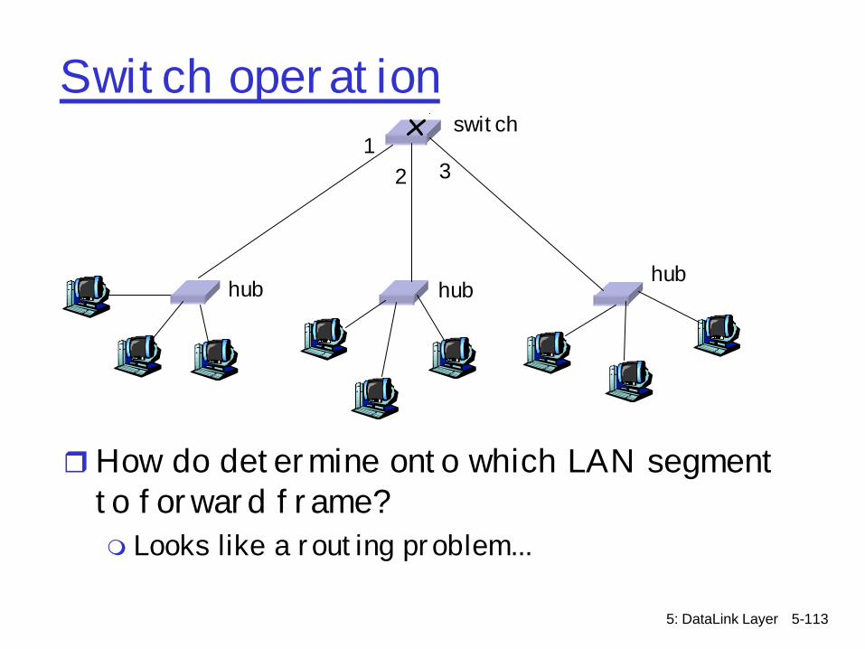
Switch operation
rHow do determine onto which LAN segment to forward frame?m Looks like a routing problem...
hub hubhub
switch1
2 3
5: DataLink Layer 5-114
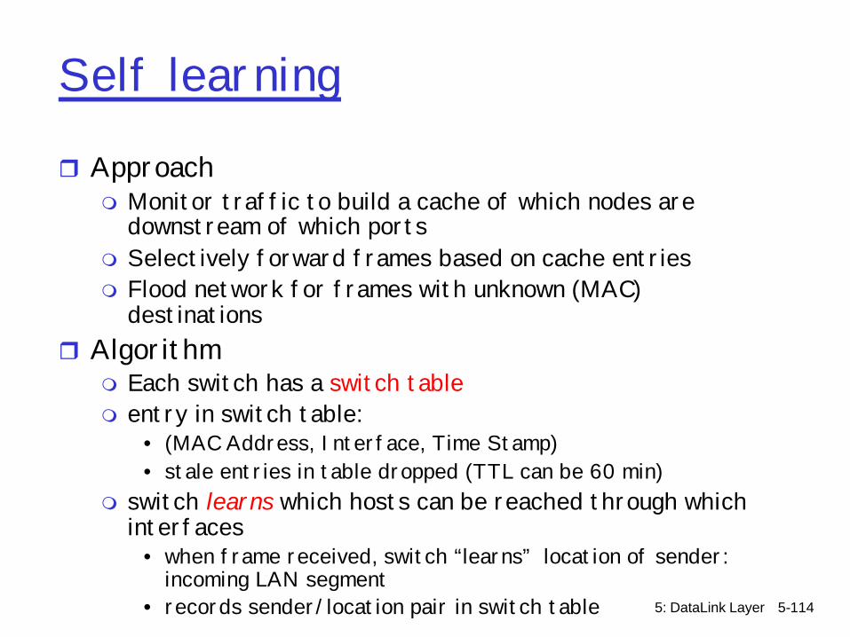
Self learning
r Approachm Monitor traffic to build a cache of which nodes are
downstream of which portsm Selectively forward frames based on cache entriesm Flood network for frames with unknown (MAC)
destinationsr Algorithm
m Each switch has a switch tablem entry in switch table:
• (MAC Address, Interface, Time Stamp)• stale entries in table dropped (TTL can be 60 min)
m switch learns which hosts can be reached through which interfaces
• when frame received, switch “learns” location of sender: incoming LAN segment
• records sender/location pair in switch table

5: DataLink Layer 5-115
Filtering/ForwardingWhen switch receives a frame:
index switch table using MAC dest addressif entry found for destination
then{if dest on segment from which frame arrived
then drop the frameelse forward the frame on interface indicated
}else flood
forward on all but the interface on which the frame arrived
5: DataLink Layer 5-116
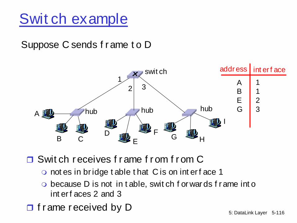
Switch exampleSuppose C sends frame to D
r Switch receives frame from from Cm notes in bridge table that C is on interface 1m because D is not in table, switch forwards frame into
interfaces 2 and 3r frame received by D
hub hub hub
switch
A
B CD
EF G H
I
address interface
ABEG
1123
12 3

5: DataLink Layer 5-117
Switch exampleSuppose D replies back with frame to C.
r Switch receives frame from from Dm notes in bridge table that D is on interface 2m because C is in table, switch forwards frame only to
interface 1r frame received by C
hub hub hub
switch
A
B CD
EF G H
I
address interface
ABEGC
11231

5: DataLink Layer 5-118
Switch: traffic isolationr switch installation breaks subnet into LAN
segmentsr switch filters packets:m same-LAN-segment frames not usually
forwarded onto other LAN segmentsm segments become separate collision domains
hub hub hub
switch
collision domain collision domain
collision domain
5: DataLink Layer 5-119
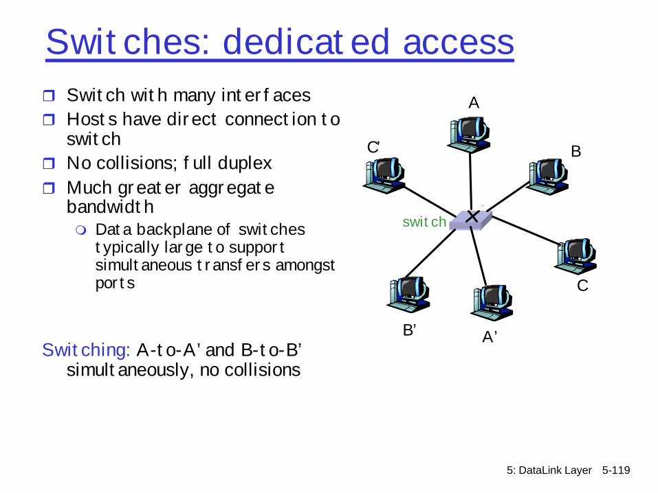
Switches: dedicated accessr Switch with many interfacesr Hosts have direct connection to
switchr No collisions; full duplexr Much greater aggregate
bandwidthm Data backplane of switches
typically large to support simultaneous transfers amongst ports
Switching: A-to-A’ and B-to-B’ simultaneously, no collisions
switch
A
A’
B
B’
C
C’
5: DataLink Layer 5-120
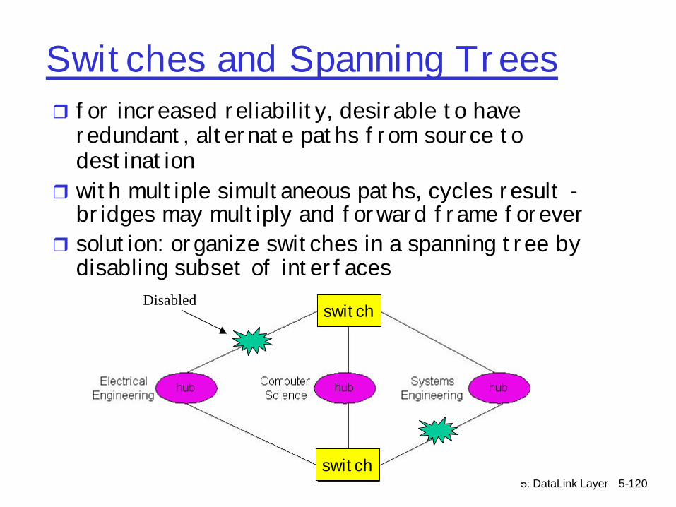
Switches and Spanning Treesr for increased reliability, desirable to have
redundant, alternate paths from source to destination
r with multiple simultaneous paths, cycles result -bridges may multiply and forward frame forever
r solution: organize switches in a spanning tree by disabling subset of interfaces
Disabled
switch
switch

5: DataLink Layer 5-121
Switches vs. Routersr both store-and-forward devices
m routers: network layer devices (examine network layer headers)
m switches/bridges are link Layer devicesr routers maintain routing tables, implement routing
algorithmsr swtiches maintain filtering tables, implement
filtering, learning and spanning tree algorithmsr why can't the Internet be one great big switch?

5: DataLink Layer 5-122
Routers vs. Switches
Switches + and -+ Switch operation is simpler requiring less processing
bandwidth- Topologies are restricted with switches: a spanning tree must
be built to avoid cycles - Switches do not offer protection from broadcast storms
(endless broadcasting by a host will be forwarded by a switch)
5: DataLink Layer 5-123
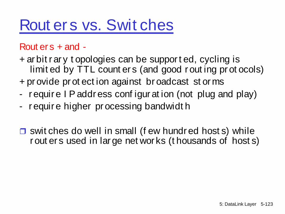
Routers vs. SwitchesRouters + and -+ arbitrary topologies can be supported, cycling is
limited by TTL counters (and good routing protocols)+ provide protection against broadcast storms- require IP address configuration (not plug and play)- require higher processing bandwidth
r switches do well in small (few hundred hosts) while routers used in large networks (thousands of hosts)
5: DataLink Layer 5-124
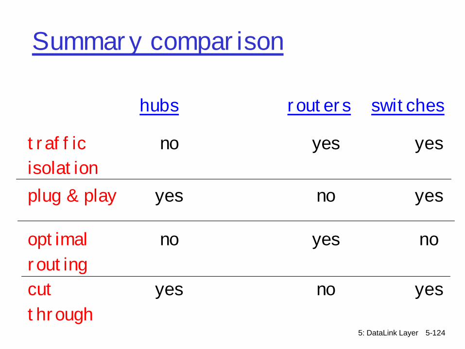
Summary comparison
hubs routers switches
traffic isolation
no yes yes
plug & play yes no yes
optimal routing
no yes no
cut through
yes no yes

5: DataLink Layer 5-125
Link Layer
r 5.1 Introduction and services
r 5.2 Error detection and correction
r 5.3Multiple access protocols
r 5.4 Link-Layer Addressing
r 5.5 Ethernet and other data link layers
r 5.6 Hubs and switchesr 5.7 PPPr 5.8 Link Virtualization:
ATM

5: DataLink Layer 5-126
Point to Point Data Link Controlr Point-to-point links
m One sender, one receiver, one linkm Easier than shared broadcast links
• No media access control• No need for explicit MAC addressing (ie ARP)
r Goal of Point-to-Point protocolsm Layer generic “higher-level” data-link layer functions on top of
a variety of point-to-point links• Dial-up phone line, DSL, ISDN etc.• Each different link does its own digital-analog conversion (ie
provides bits)• Implement pseudo-link layer on top that implements common
functions– Framing, Demux to upper layer, etc.
r Examplesm PPP (point-to-point protocol)m HDLC: High level data link control (Data link used to be
considered “high layer” in protocol stack!)
5: DataLink Layer 5-127
PPP Design Requirements [RFC 1557]
r packet framing: encapsulation of network-layer datagram in data link frame m carry network layer data of any network layer
protocol (not just IP) at same timer demultiplex upwardsr bit transparency: must carry any bit pattern in the
data fieldr error detection (no correction)r connection liveness: detect, signal link failure to
network layerr network layer address negotiation: endpoint can
learn/configure each other’s network address
5: DataLink Layer 5-128
PPP non-requirements
r no error correction/recoveryr no flow controlr out of order delivery OK r no need to support multipoint links (e.g., polling)
Error recovery, flow control, data re-ordering all relegated to higher layers!
5: DataLink Layer 5-129
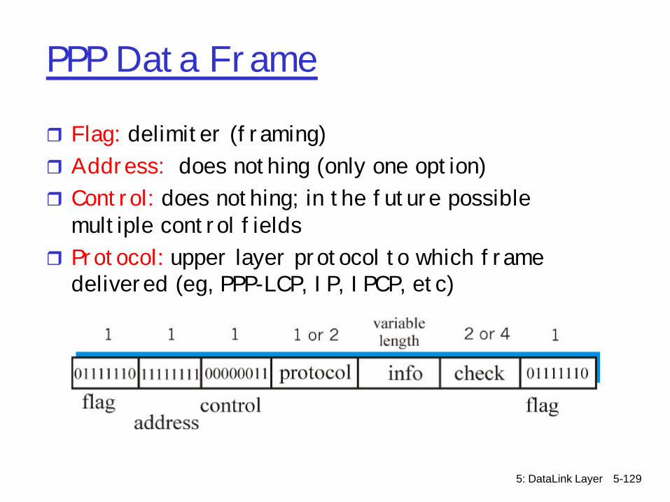
PPP Data Frame
r Flag: delimiter (framing)r Address: does nothing (only one option)r Control: does nothing; in the future possible
multiple control fieldsr Protocol: upper layer protocol to which frame
delivered (eg, PPP-LCP, IP, IPCP, etc)
5: DataLink Layer 5-130
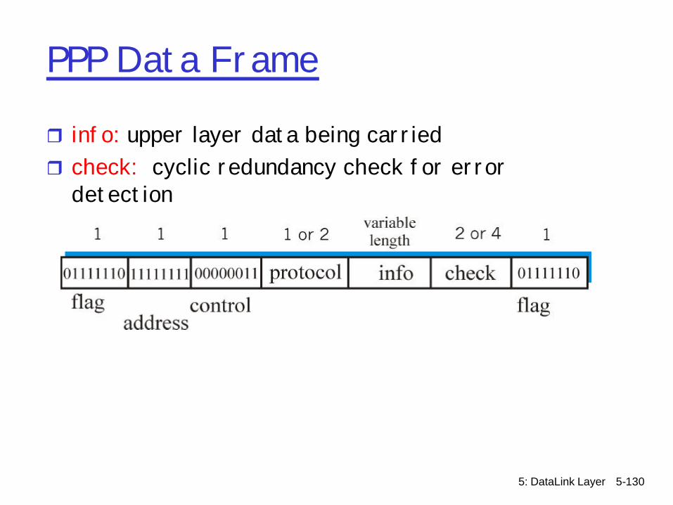
PPP Data Frame
r info: upper layer data being carriedr check: cyclic redundancy check for error
detection

5: DataLink Layer 5-131
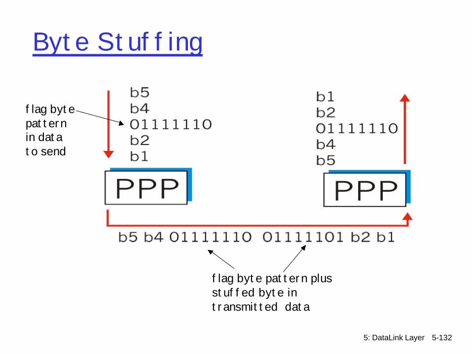
Byte Stuffingr “data transparency” requirement: data field must
be allowed to include flag pattern <01111110>mQ: is received <01111110> data or flag?
r Sender: adds (“stuffs”) extra < 01111101> byte before each < 01111110> data byte
r Receiver:m two 01111101 byte followed by 01111110 byte:
discard first byte, continue data receptionm single 01111110: flag byte
5: DataLink Layer 5-132
Byte Stuffing
flag bytepatternin datato send
flag byte pattern plusstuffed byte in transmitted data

5: DataLink Layer 5-133
PPP Data Control ProtocolBefore exchanging network-
layer data, data link peers must
r configure PPP link (max. frame length, authentication)
r learn/configure networklayer informationm for IP: carry IP Control
Protocol (IPCP) msgs (protocol field: 8021) to configure/learn IP address
5: DataLink Layer 5-134
Link Layer
r 5.1 Introduction and services
r 5.2 Error detection and correction
r 5.3Multiple access protocols
r 5.4 Link-Layer Addressing
r 5.5 Ethernet and other data link layers
r 5.6 Hubs and switchesr 5.7 PPPr 5.8 Link Virtualization:
ATM and MPLS
5: DataLink Layer 5-135
Virtualization of networks
Virtualization of resources: a powerful abstraction in systems engineering:
r computing examples: virtual memory, virtual devicesm Virtual machines: e.g., javam IBM VM os from 1960’s/70’s
r layering of abstractions: don’t sweat the details of the lower layer, only deal with lower layers abstractly

5: DataLink Layer 5-136
The Internet: virtualizing networks
1974: multiple unconnected nets mARPAnetm data-over-cable networksm packet satellite network (Aloha)m packet radio network
… differing in:m addressing conventionsm packet formatsm error recoverym routing
ARPAnet satellite net"A Protocol for Packet Network Intercommunication", V. Cerf, R. Kahn, IEEE Transactions on Communications,May, 1974, pp. 637-648.

5: DataLink Layer 5-137
The Internet: virtualizing networks
ARPAnet satellite net
gateway
Internetwork layer (IP): r addressing: internetwork
appears as a single, uniform entity, despite underlying local network heterogeneity
r network of networks
Gateway: r “embed internetwork packets in
local packet format or extract them”
r route (at internetwork level) to next gateway
5: DataLink Layer 5-138
Cerf & Kahn’s Internetwork Architecture
What is virtualized?r two layers of addressing: internetwork and local
networkr new layer (IP) makes everything homogeneous at
internetwork layerr underlying local network technology m cablem satellitem 56K telephone modemm today: ATM, MPLS
… “invisible” at internetwork layer. Looks like a link layer technology to IP!

5: DataLink Layer 5-139
Virtual links and tunneling
rMany options of encapsulating or tunnelingpackets through a “virtual link” (VPN)m Generic Routing Encapsulation (GRE)
• PPTP (Point-to-point Tunneling Protocol)• L2F (Layer 2 Forwarding)• L2TP (Layer 2 Tunneling Protocol)
m Example• Encrypt data at a layer below network layer• IPsec only works for IP packets• Allows encryption at data-link layer
rCan also be done at network layer via IPsec
5: DataLink Layer 5-140
ATM and MPLS
rATM, MPLS separate networks in their own rightm different service models, addressing, routing
from Internetr viewed by Internet as logical link connecting
IP routersm just like dialup link is really part of separate
network (telephone network)

5: DataLink Layer 5-141
Multiprotocol label switching (MPLS)
r initial goal: speed up IP forwarding by using fixed length label (instead of IP address) to do forwarding m borrowing ideas from Virtual Circuit (VC) approachm but IP datagram still keeps IP address!
PPP or Ethernet header
IP header remainder of link-layer frameMPLS header
label Exp S TTL
20 3 1 5

5: DataLink Layer 5-142
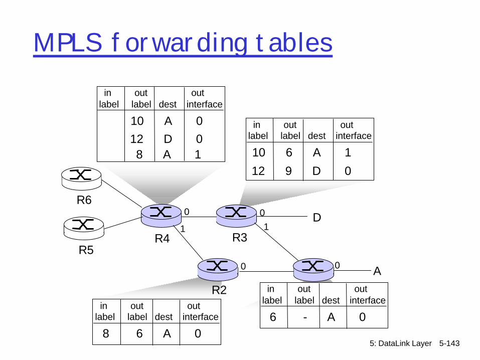
MPLS capable routers
r a.k.a. label-switched routerr forwards packets to outgoing interface based
only on label value (don’t inspect IP address)mMPLS forwarding table distinct from IP forwarding
tablesr signaling protocol needed to set up forwardingm RSVP-TEm forwarding possible along paths that IP alone would
not allow (e.g., source-specific routing) !!m use MPLS for traffic engineering
rmust co-exist with IP-only routers
5: DataLink Layer 5-143
R1R2
D
R3R4R5
0
100
A
R6
in out outlabel label dest interface
6 - A 0
in out outlabel label dest interface
10 6 A 1
12 9 D 0
in out outlabel label dest interface
10 A 012 D 0
1
in out outlabel label dest interface
8 6 A 0
0
8 A 1
MPLS forwarding tables
5: DataLink Layer 5-144
Chapter 5: Summaryr principles behind data link layer services:
m error detection, correctionm sharing a broadcast channel: multiple accessm link layer addressing
r instantiation and implementation of various link layer technologiesm Ethernetm switched LANSm PPPm virtualized networks as a link layer: ATM, MPLS
5: DataLink Layer 5-145
Physical Layerr Plethora of physical media
m Fiber, copper, airm Specifies the characteristics of transmission
mediam Too many to cover in detail, not the focus of the
coursem Many data-link layer protocols (i.e. Ethernet,
Token-Ring, FDDI. ATM run across multiple physical layers)
m Physical characteristics dictate suitability of data-link layer protocol and bandwidth limits

5: DataLink Layer 5-146
Digital to analog conversion
r Bits sent as analog signalsm Photonic pulses of a given wavelength over
optical fiberm Electronic signals of a given voltage

5: DataLink Layer 5-147
Digital to analog conversion
rWill cover electronic transmission (optical transmission left for you to research)
r Biggest issuemWhen to sample voltage?m Detecting sequences involves clocking with the
same clock• How to synchronize sender and receiver clocks?
mNeed easily detectible event at both ends• Signal transitions help resync sender and receiver• Need frequent transitions to prevent clock skew
m http://www.mouse.demon.nl/ckp/telco/encode.htm

5: DataLink Layer 5-148
RZ
r Return to Zero (RZ)m 1=pulse to high, dropping back to lowm 0=no transition
5: DataLink Layer 5-149
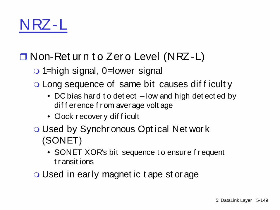
NRZ-L
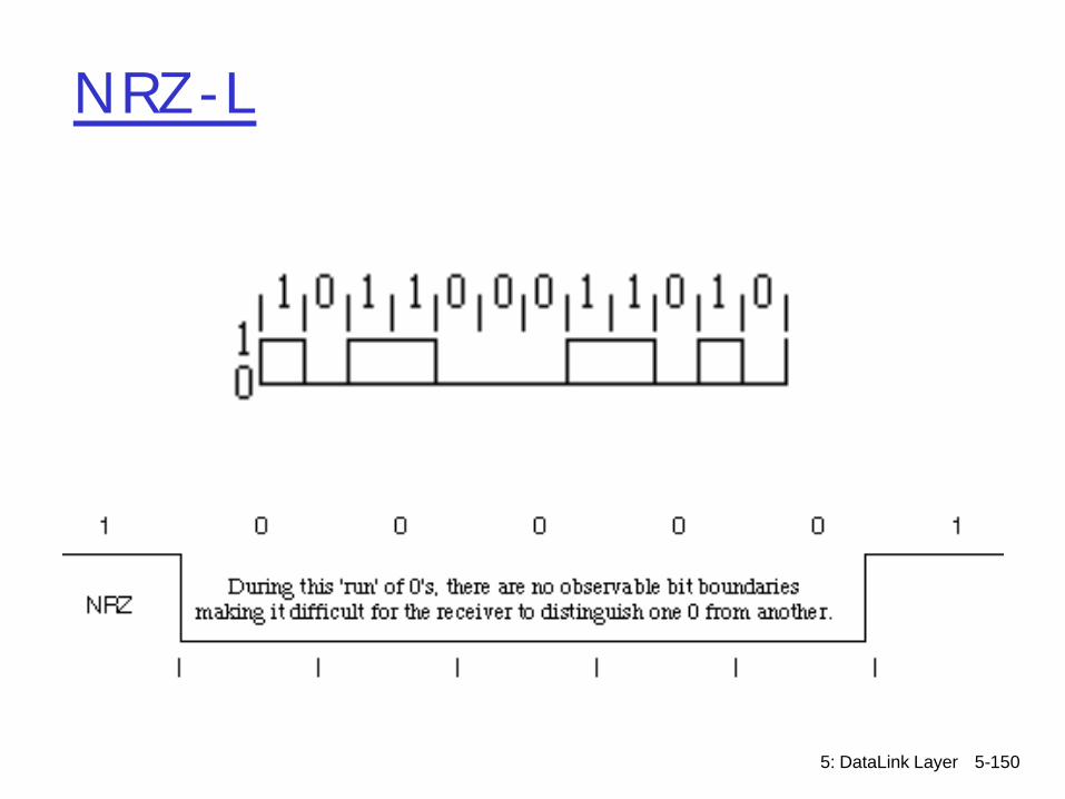
rNon-Return to Zero Level (NRZ-L)m 1=high signal, 0=lower signalm Long sequence of same bit causes difficulty
• DC bias hard to detect – low and high detected by difference from average voltage
• Clock recovery difficultm Used by Synchronous Optical Network
(SONET)• SONET XOR’s bit sequence to ensure frequent
transitionsm Used in early magnetic tape storage
5: DataLink Layer 5-150
NRZ-L
5: DataLink Layer 5-151
NRZ-M
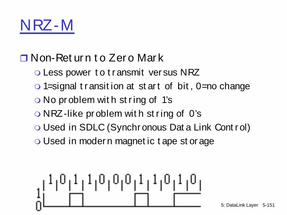
rNon-Return to Zero Markm Less power to transmit versus NRZm 1=signal transition at start of bit, 0=no changemNo problem with string of 1’smNRZ-like problem with string of 0’sm Used in SDLC (Synchronous Data Link Control)m Used in modern magnetic tape storage

5: DataLink Layer 5-152
NRZ-S
rNon-Return to Zero Spacem 1=no change, 0=signal transition at start of bitmNo problem with string of 0’smNRZ-like problem with string of 1’s
5: DataLink Layer 5-153
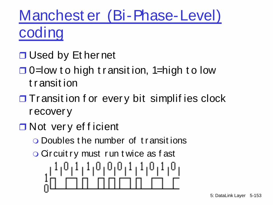
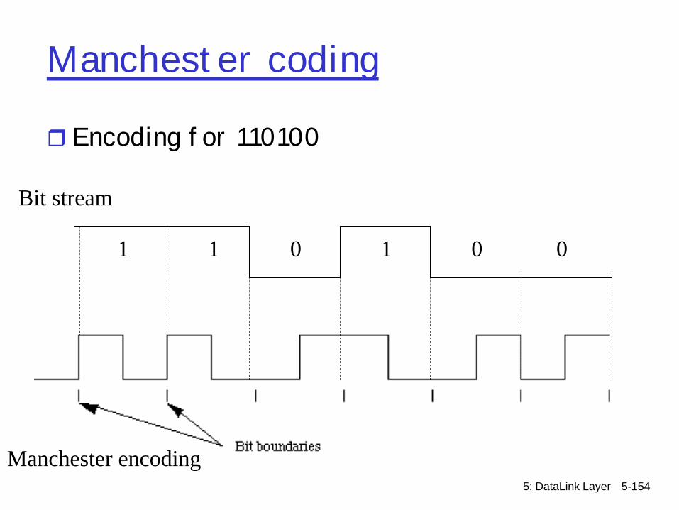
Manchester (Bi-Phase-Level) codingrUsed by Ethernetr 0=low to high transition, 1=high to low
transitionrTransition for every bit simplifies clock
recoveryrNot very efficientm Doubles the number of transitionsm Circuitry must run twice as fast
5: DataLink Layer 5-154
Manchester coding
r Encoding for 110100
Bit stream
1 1 0 1 0 0
Manchester encoding
5: DataLink Layer 5-155
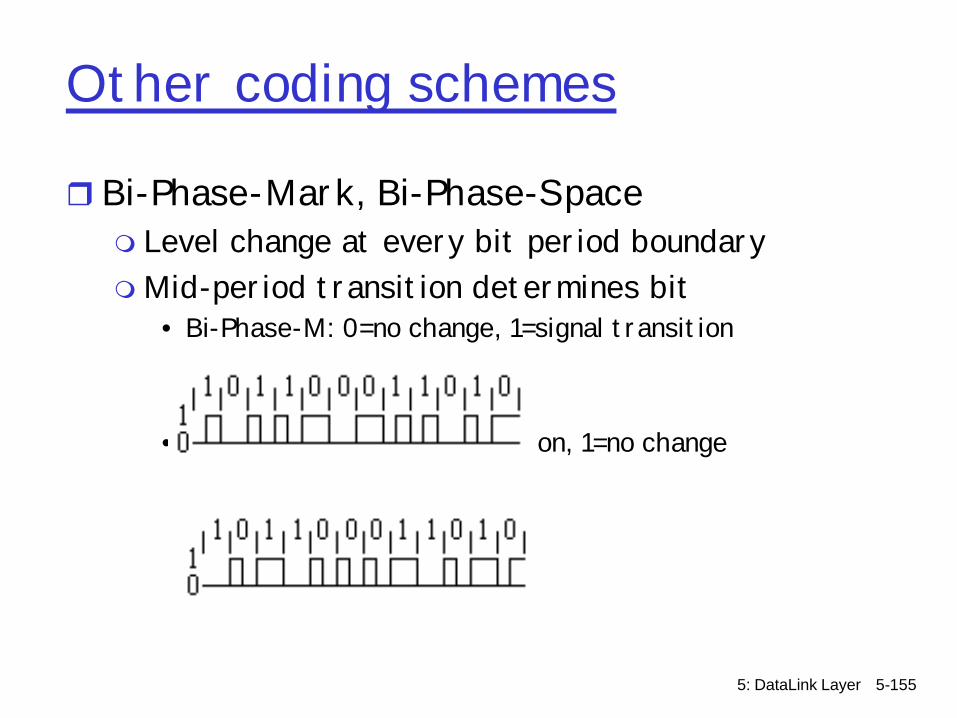
Other coding schemes
r Bi-Phase-Mark, Bi-Phase-Spacem Level change at every bit period boundarymMid-period transition determines bit
• Bi-Phase-M: 0=no change, 1=signal transition
• Bi-Phase-S: 0=signal transition, 1=no change
5: DataLink Layer 5-156
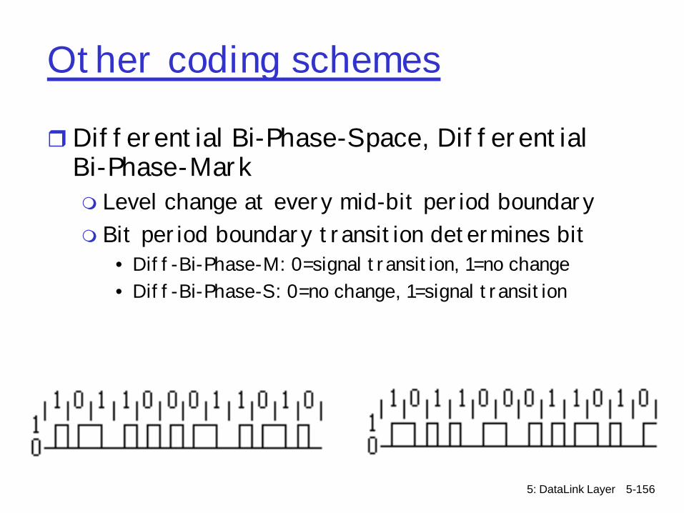
Other coding schemes
rDifferential Bi-Phase-Space, Differential Bi-Phase-Markm Level change at every mid-bit period boundarym Bit period boundary transition determines bit
• Diff-Bi-Phase-M: 0=signal transition, 1=no change• Diff-Bi-Phase-S: 0=no change, 1=signal transition
5: DataLink Layer 5-157
Common Cabling
r Copperm Twisted Pair
• Unshielded (UTP)– CAT-1, CAT-2, CAT-3, CAT-4, CAT-5, CAT-5e
• Shielded (STP)m Coaxial Cable
r Fiberm Single-modemMulti-mode
5: DataLink Layer 5-158
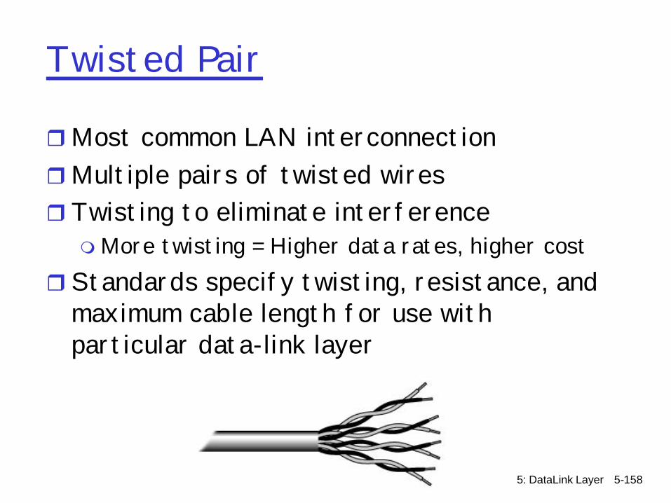
Twisted Pair
rMost common LAN interconnectionrMultiple pairs of twisted wiresrTwisting to eliminate interferencemMore twisting = Higher data rates, higher cost
rStandards specify twisting, resistance, and maximum cable length for use with particular data-link layer
5: DataLink Layer 5-159
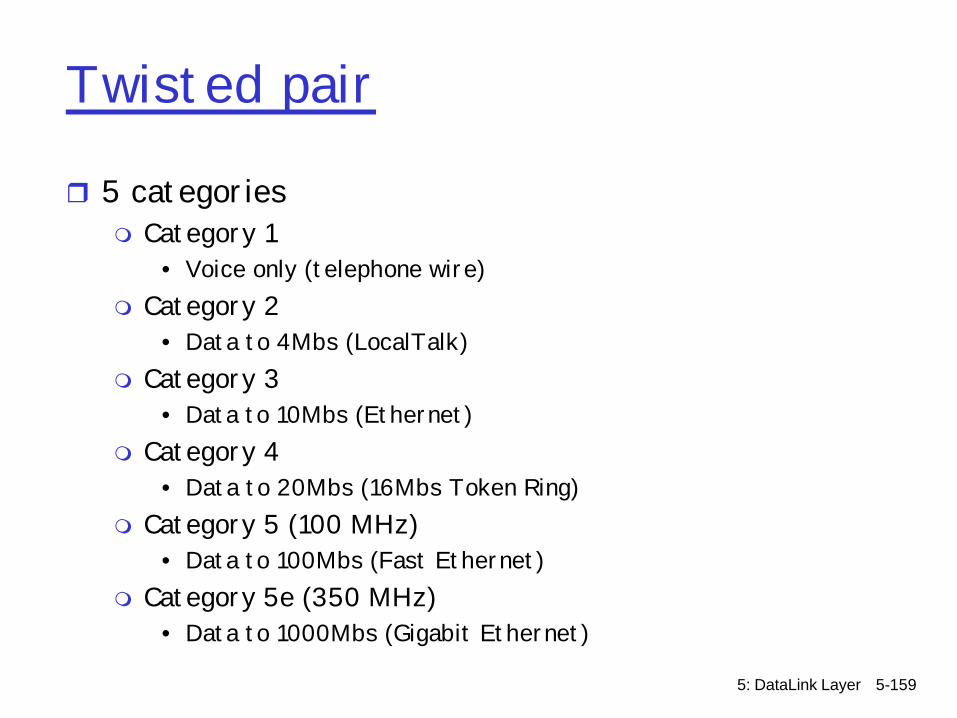
Twisted pair
r 5 categoriesm Category 1
• Voice only (telephone wire)m Category 2
• Data to 4Mbs (LocalTalk)m Category 3
• Data to 10Mbs (Ethernet)m Category 4
• Data to 20Mbs (16Mbs Token Ring)m Category 5 (100 MHz)
• Data to 100Mbs (Fast Ethernet)m Category 5e (350 MHz)
• Data to 1000Mbs (Gigabit Ethernet)

5: DataLink Layer 5-160
Twisted Pair
r Common connectors for Twisted Pairm RJ11 (3 pairs)m RJ45 (4 pairs)
• Allows both data and phone connections• (1,2) and (3,6) for data, (4,5) for voice• Crossover cables for NIC-NIC, Hub-Hub connection
(Data pairs swapped)

5: DataLink Layer 5-161
UTP
rUnshielded Twisted Pairm Limited amount of protection from
interferencem Commonly used for voice and ethernet
• Voice: multipair 100-ohm UTP
5: DataLink Layer 5-162
STP
rShielded Twisted PairmNot as common at UTPm UTP susceptible to radio and electrical
interferencem Extra shielding material addedm Cables heavier, bulkier, and more costlymOften used in token ring topologies
• 150 ohm STP two pair (IEEE 802.5 Token Ring)

5: DataLink Layer 5-163
Coaxial cable
rSingle copper conductor at centerr Plastic insulation layerrHighly resistant to interferencem Braided metal shield m Support longer connectivity distances over UTP

5: DataLink Layer 5-164
Coaxial cable
rThick (10Base5) m Large diameter 50-ohm cablemN connectors
rThin (10Base2) cablesm Small diameter 50-ohm cablem BNC, RJ-58 connector
r Video cablem 75-ohm cablem BNC, RJ-59 connectormNot compatible with RJ-58
5: DataLink Layer 5-165
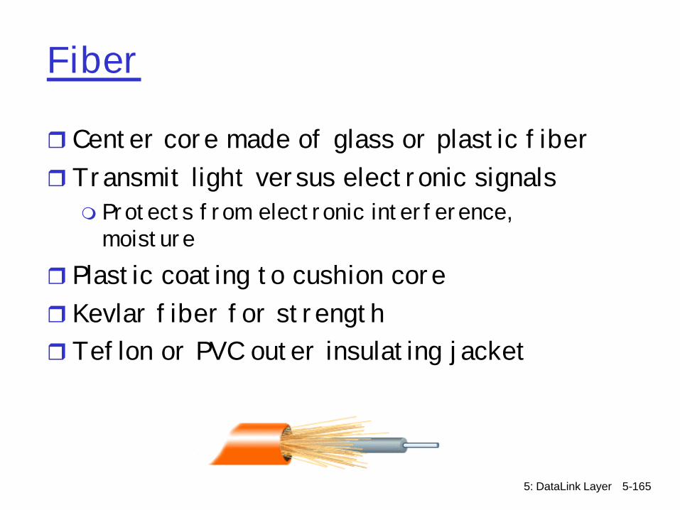
Fiber
r Center core made of glass or plastic fiberrTransmit light versus electronic signalsm Protects from electronic interference,
moisturer Plastic coating to cushion corer Kevlar fiber for strengthrTeflon or PVC outer insulating jacket
5: DataLink Layer 5-166
Fiber
r Single-mode fiberm Smaller diameter (12.5 microns)m One mode onlym Preserves signal better over longer distancesm Typically used for SONET or SDHm Lasers used to signalm More expensive
r Multi-mode fiberm Larger diameter (62.5 microns)m Multiple modesm LEDs used to signalm WDM and DWDM
r Photodiodes at receivers
5: DataLink Layer 5-167
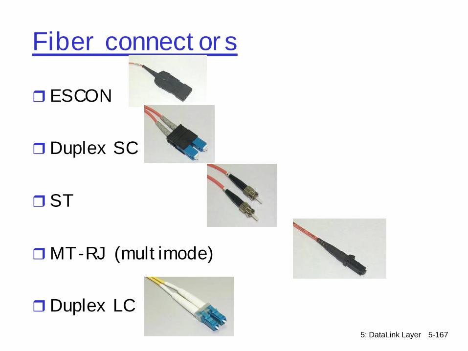
Fiber connectors
r ESCON
rDuplex SC
rST
rMT-RJ (multimode)
rDuplex LC

5: DataLink Layer 5-168
Physical-link lingo
rSpecifies capacities over physical mediar Electronicm T1/DS1=1.54 Mbps m T3/DS3=45Mbps
rOptical (OC=optical carrier)mOC1=52 MbpsmOC3/STM1=156 MbpsmOC12=622 MbpsmOC48=2488 MbpsmOC192=10 Gbps mOC768=40 Gbps

5: DataLink Layer 5-169
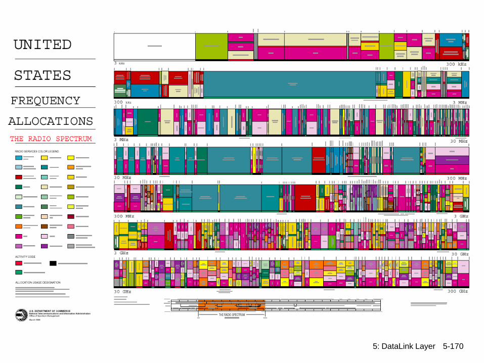
Wireless
r Entire spectrum of transmission frequency rangesm Radiom Infraredm Lasersm Cellular telephone m Microwave m Satellitem Acoustic (see ESE sensors)m Ultra-wide band
r http://www.ntia.doc.gov/osmhome/allochrt.html
5: DataLink Layer 5-170

5: DataLink Layer 5-171
What runs on them?Protocol Summary
Protocol Cable Speed Topology
Ethernet Twisted Pair, Coaxial, Fiber 10 Mbps Linear Bus, Star, Tree
Fast Ethernet Twisted Pair, Fiber 100 Mbps Star
LocalTalk Twisted Pair .23 Mbps Linear Bus or Star
Token Ring Twisted Pair 4 Mbps - 16 Mbps Star-Wired Ring
FDDI Fiber 100 Mbps Dual ring
ATM Twisted Pair, Fiber 155-2488 Mbps Linear Bus, Star, Tree
5: DataLink Layer 5-172
Extra slides

5: DataLink Layer 5-173
DL: ARQ
rAutomatic Repeat Request (ARQ)m Receiver sends acknowledgement (ACK) when it
receives packetm Sender waits for ACK and timeouts if it does
not arrive within some time period
5: DataLink Layer 5-174
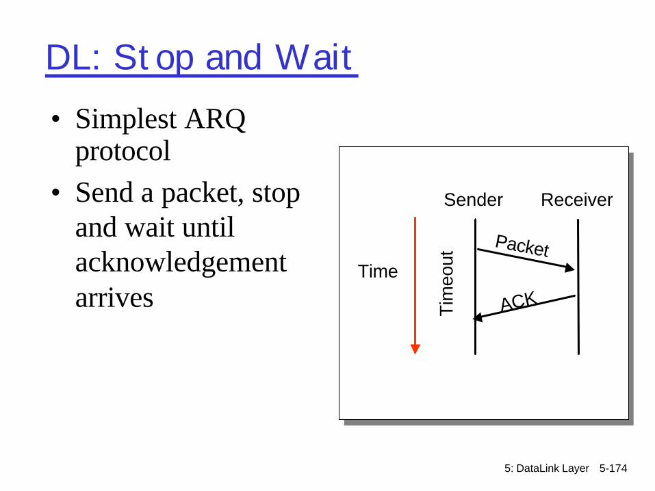
DL: Stop and Wait
Time
Packet
ACKTim
eout
• Simplest ARQ protocol
• Send a packet, stop and wait until acknowledgement arrives
Sender Receiver

5: DataLink Layer 5-175
DL: Recovering from Error
Packet
ACK
Tim
eout
Packet
ACK
Tim
eout
Packet
Tim
eout
Packet
ACKTi
meo
ut
Time
Packet
ACK
Tim
eout
Packet
ACK
Tim
eout
ACK lost Packet lost Early timeout
5: DataLink Layer 5-176
DL: Stop and Wait Problems
rHow to recognize a duplicate?r Performancem Can only send one packet per round trip
5: DataLink Layer 5-177
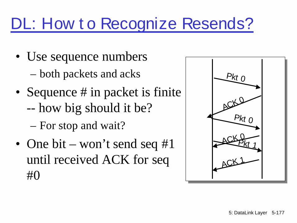
DL: How to Recognize Resends?
• Use sequence numbers– both packets and acks
• Sequence # in packet is finite -- how big should it be? – For stop and wait?
• One bit – won’t send seq #1 until received ACK for seq#0
Pkt 0
ACK 0
Pkt 0
ACK 1
Pkt 1ACK 0

5: DataLink Layer 5-178
DL: How to Keep the Pipe Full?r Send multiple packets without
waiting for first to be ackedm Number of pkts in flight = window
r How large a window is neededm Round trip delay * bandwidth =
capacity of piper Reliable, unordered delivery
m Several parallel stop & waitsm Send new packet after each ackm Sender keeps list of unack’ed packets;
resends after timeoutm Receiver same as stop&wait

5: DataLink Layer 5-179
DL: Sliding Window
r Reliable, ordered deliveryr Receiver has to hold onto a packet until all
prior packets have arrivedrSender must prevent buffer overflow at
receiverr Circular buffer at sender and receiverm Packets in transit <= buffer size m Advance when sender and receiver agree
packets at beginning have been received
5: DataLink Layer 5-180
ReceiverSender
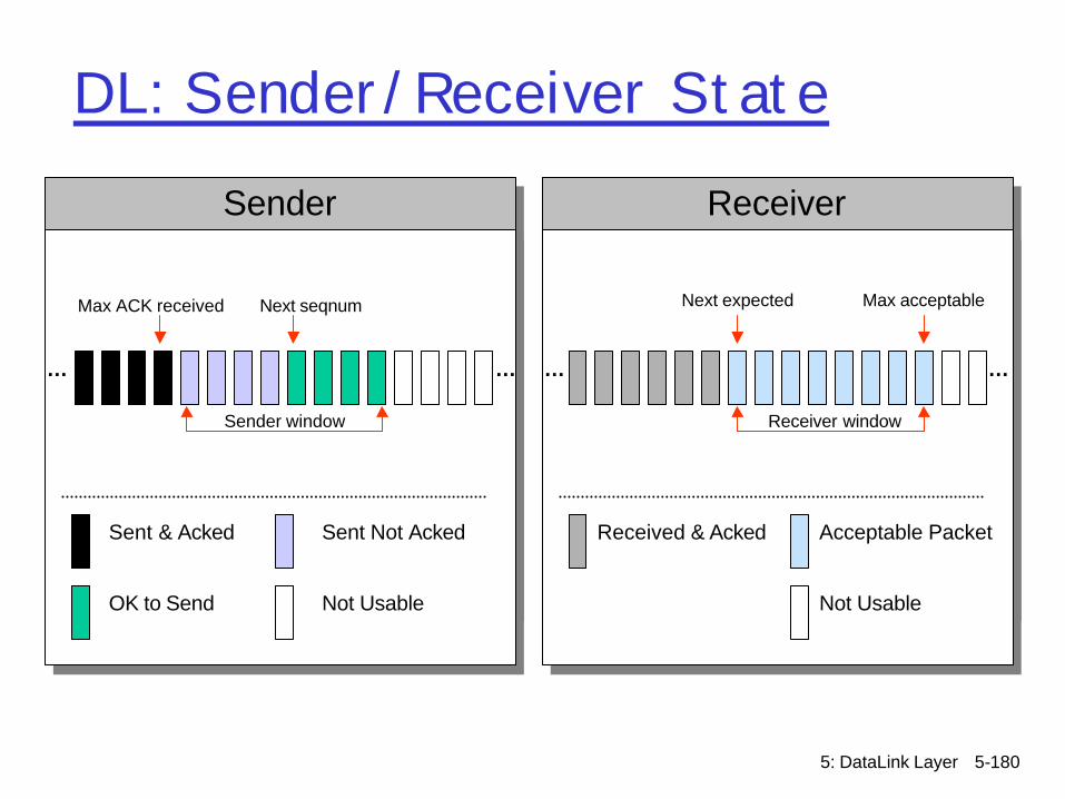
DL: Sender/Receiver State
… …
Sent & Acked Sent Not Acked
OK to Send Not Usable
… …
Max acceptable
Receiver window
Max ACK received Next seqnum
Received & Acked Acceptable Packet
Not Usable
Sender window
Next expected
5: DataLink Layer 5-181
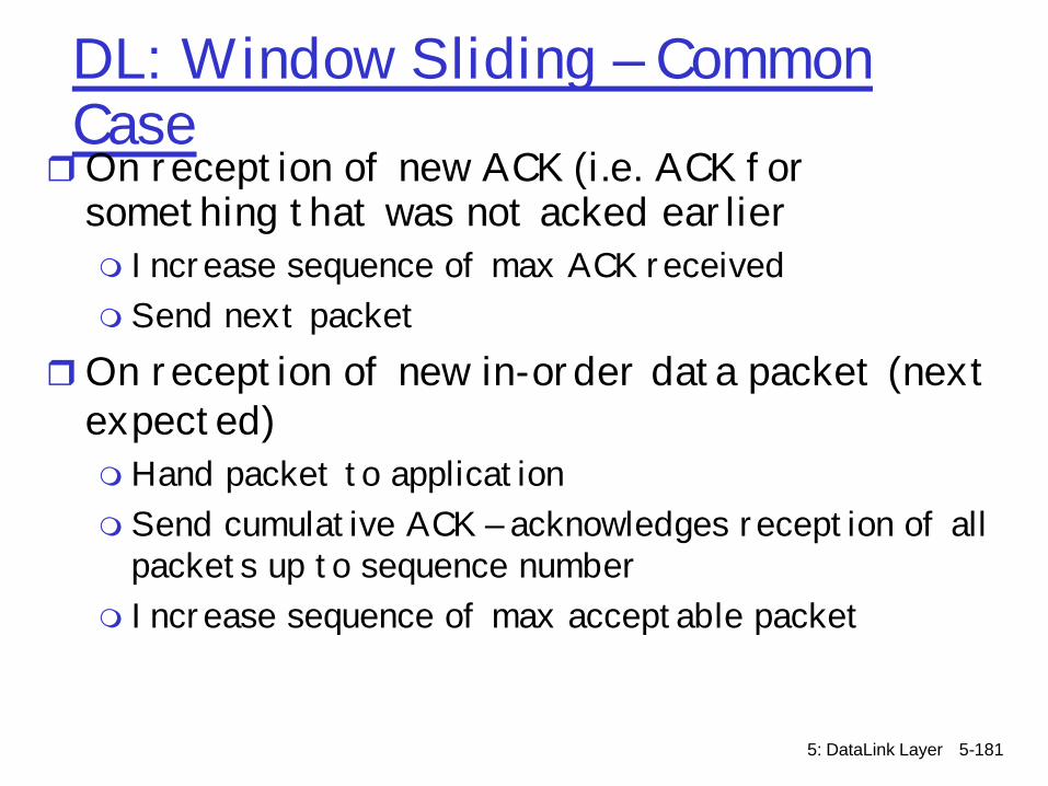
DL: Window Sliding – Common CaserOn reception of new ACK (i.e. ACK for
something that was not acked earlierm Increase sequence of max ACK receivedm Send next packet
rOn reception of new in-order data packet (next expected)mHand packet to applicationm Send cumulative ACK – acknowledges reception of all
packets up to sequence numberm Increase sequence of max acceptable packet
5: DataLink Layer 5-182
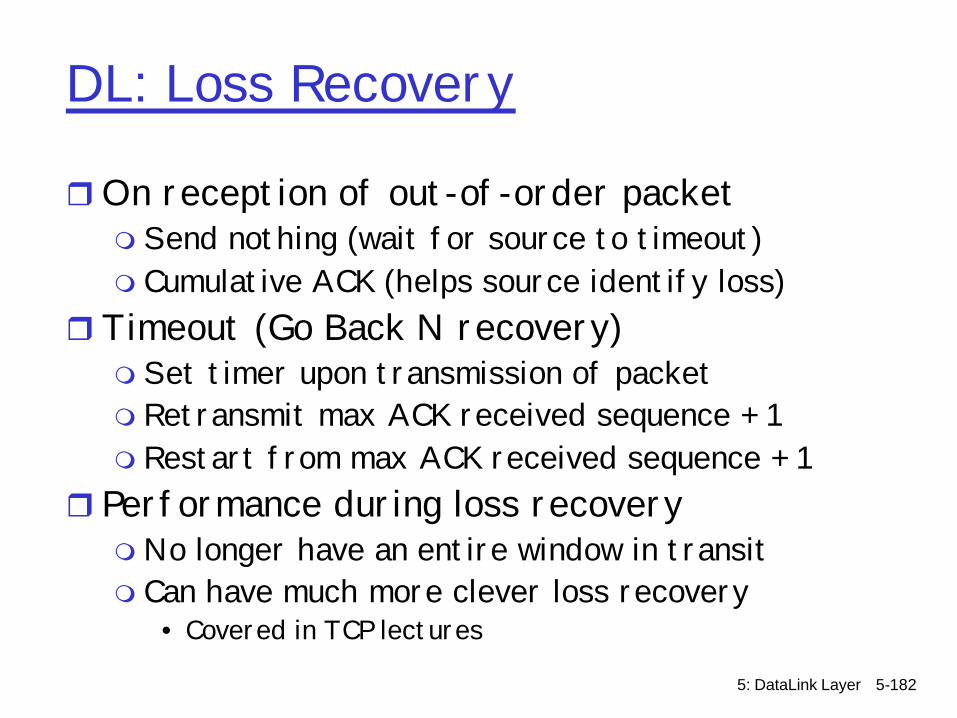
DL: Loss Recovery
rOn reception of out-of-order packetm Send nothing (wait for source to timeout)m Cumulative ACK (helps source identify loss)
rTimeout (Go Back N recovery)m Set timer upon transmission of packetm Retransmit max ACK received sequence + 1m Restart from max ACK received sequence + 1
r Performance during loss recoverymNo longer have an entire window in transitm Can have much more clever loss recovery
• Covered in TCP lectures

5: DataLink Layer 5-183
DL: Sequence Numbers
rHow large do sequence numbers need to be?mMust be able to detect wrap-aroundm Depends on sender/receiver window size
r E.g.mMax seq = 7, send win=recv win=7m If pkts 0..6 are sent succesfully and all acks
lost• Receiver expects 7,0..5, sender retransmits old 0..6
rMax sequence must be >= send window + recv window

5: DataLink Layer 5-184
Checksumming: Cyclic Redundancy Checkr view data bits, D, as a binary numberr choose r+1 bit pattern (generator), Gr goal: choose r CRC bits, R, such that
m <D,R> exactly divisible by G (modulo 2) m receiver knows G, divides <D,R> by G. If non-zero remainder:
error detected!m can detect all burst errors less than r+1 bits
r widely used in practice (ATM, HDCL)

5: DataLink Layer 5-185
Manchester encoding
r Used in 10BaseTr Each bit has a transitionr Allows clocks in sending and receiving nodes to
synchronize to each otherm no need for a centralized, global clock among nodes!
r Hey, this is physical-layer stuff!m More later
5: DataLink Layer 5-186
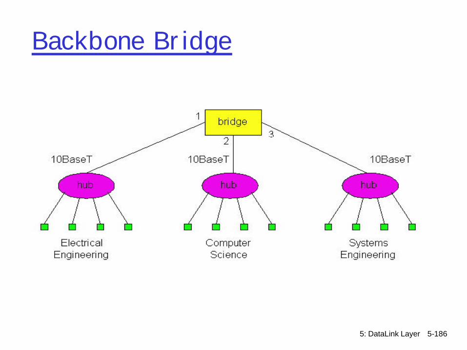
Backbone Bridge
5: DataLink Layer 5-187
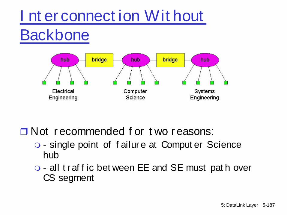
Interconnection Without Backbone
rNot recommended for two reasons:m - single point of failure at Computer Science
hubm - all traffic between EE and SE must path over
CS segment

5: DataLink Layer 5-188
CSMA/CD efficiency
r Tprop = max prop between 2 nodes in LANr ttrans = time to transmit max-size frame
r Efficiency goes to 1 as tprop goes to 0r Goes to 1 as ttrans goes to infinityr Much better than ALOHA, but still decentralized,
simple, and cheap
transprop tt /511
efficiency+
=
5: DataLink Layer 5-189
More on Switches
r cut-through switching: frame forwarded from input to output port without first collecting entire framemslight reduction in latency
r combinations of shared/dedicated, 10/100/1000 Mbps interfaces

5: DataLink Layer 5-190
Institutional network
hub hubhub
switch
to externalnetwork
router
IP subnet
mail server
web server
5: DataLink Layer 5-191
ATM
rATMm Replace existing Internet protocols with a more
“robust” architecturemNetwork architecture to support
• Multiple service classes and per-flow guarantees• Virtual circuits to support real-time applications• Explicit rate signaling and resource allocation
r Covered as a data-link layer…
5: DataLink Layer 5-192
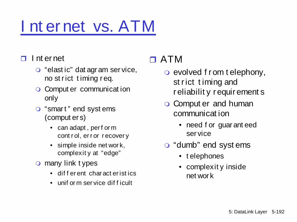
Internet vs. ATM
r Internetm “elastic” datagram service,
no strict timing req. m Computer communication
onlym “smart” end systems
(computers)• can adapt, perform
control, error recovery• simple inside network,
complexity at “edge”m many link types
• different characteristics• uniform service difficult
r ATMm evolved from telephony,
strict timing and reliability requirements
m Computer and human communication
• need for guaranteed service
m “dumb” end systems• telephones• complexity inside
network
5: DataLink Layer 5-193
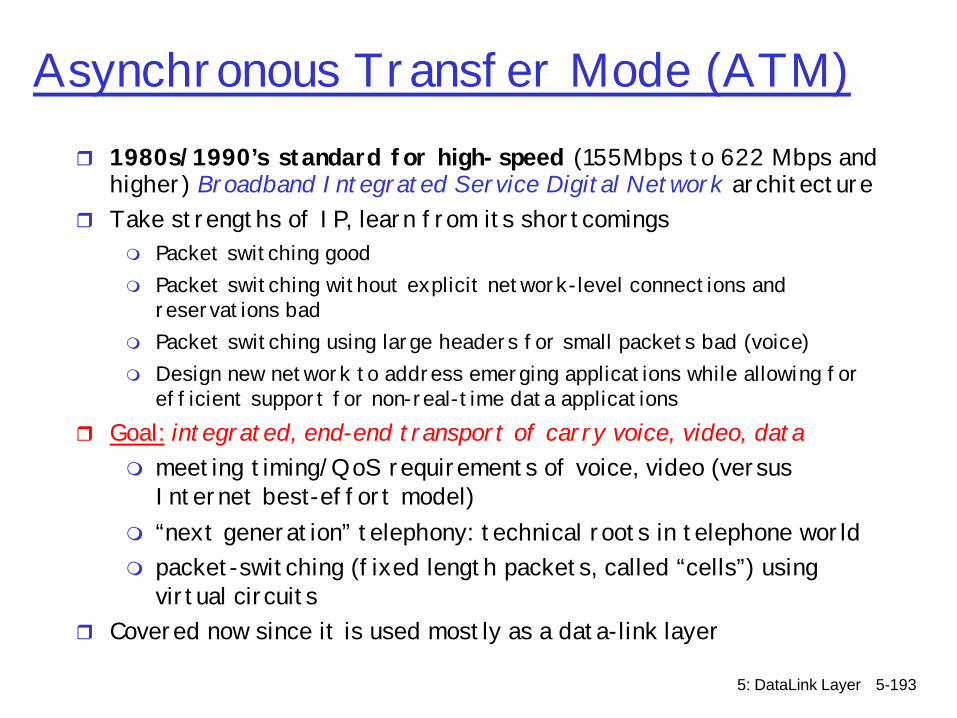
Asynchronous Transfer Mode (ATM)r 1980s/1990’s standard for high-speed (155Mbps to 622 Mbps and
higher) Broadband Integrated Service Digital Network architecturer Take strengths of IP, learn from its shortcomings
m Packet switching goodm Packet switching without explicit network-level connections and
reservations badm Packet switching using large headers for small packets bad (voice)m Design new network to address emerging applications while allowing for
efficient support for non-real-time data applicationsr Goal: integrated, end-end transport of carry voice, video, data
m meeting timing/QoS requirements of voice, video (versus Internet best-effort model)
m “next generation” telephony: technical roots in telephone worldm packet-switching (fixed length packets, called “cells”) using
virtual circuitsr Covered now since it is used mostly as a data-link layer

5: DataLink Layer 5-194
ATM architecture
r adaptation layer: only at edge of ATM networkm data segmentation/reassemblym roughly analagous to Internet transport layer
r ATM layer: “network” layerm cell switching, routing
r physical layer
5: DataLink Layer 5-195
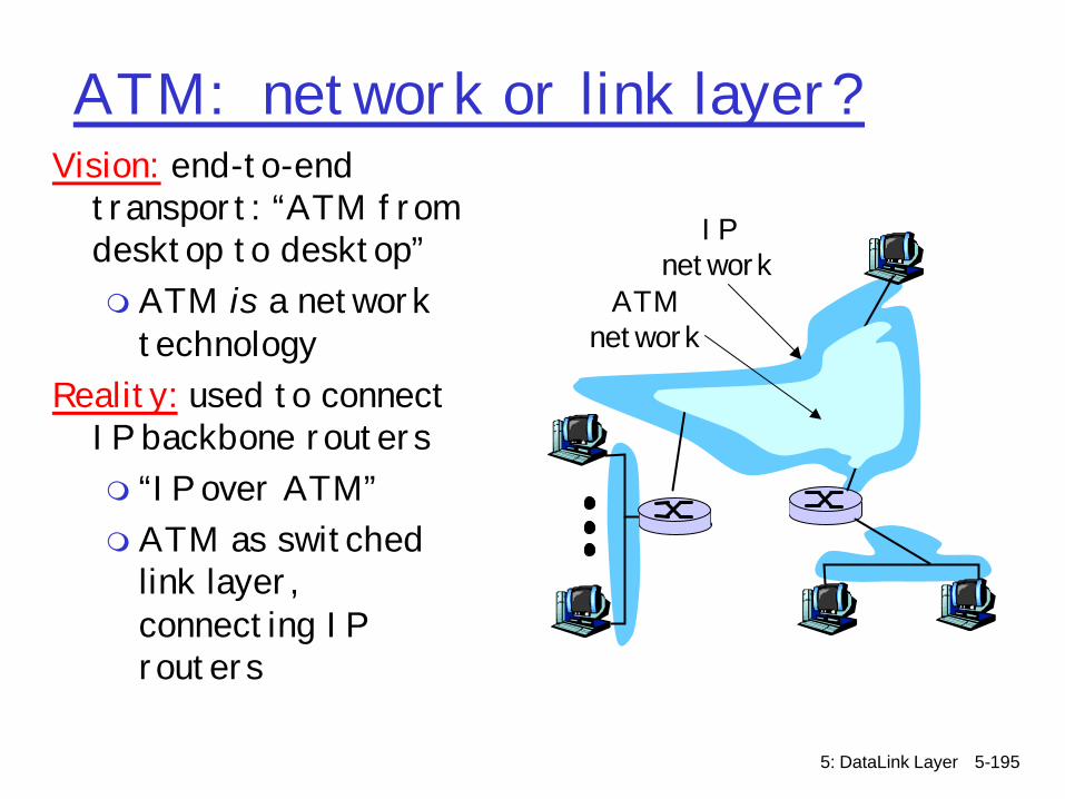
ATM: network or link layer?Vision: end-to-end
transport: “ATM from desktop to desktop”m ATM is a network
technologyReality: used to connect
IP backbone routers m “IP over ATM”m ATM as switched
link layer, connecting IP routers
ATMnetwork
IPnetwork
5: DataLink Layer 5-196
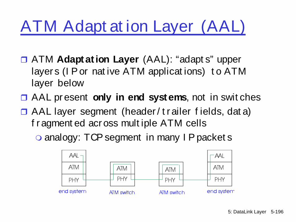
ATM Adaptation Layer (AAL)
r ATM Adaptation Layer (AAL): “adapts” upper layers (IP or native ATM applications) to ATM layer below
r AAL present only in end systems, not in switchesr AAL layer segment (header/trailer fields, data)
fragmented across multiple ATM cells m analogy: TCP segment in many IP packets
5: DataLink Layer 5-197
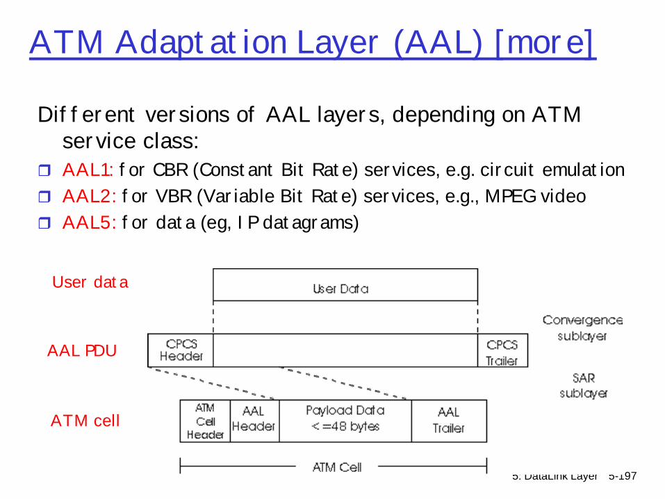
ATM Adaptation Layer (AAL) [more]
Different versions of AAL layers, depending on ATM service class:
r AAL1: for CBR (Constant Bit Rate) services, e.g. circuit emulationr AAL2: for VBR (Variable Bit Rate) services, e.g., MPEG videor AAL5: for data (eg, IP datagrams)
AAL PDU
ATM cell
User data

5: DataLink Layer 5-198
ATM LayerService: transport cells across ATM networkr analogous to IP network layerr very different services than IP network layer
NetworkArchitecture
Internet
ATM
ATM
ATM
ATM
ServiceModel
best effort
CBR
VBR
ABR
UBR
Bandwidth
none
constantrateguaranteedrateguaranteed minimumnone
Loss
no
yes
yes
no
no
Order
no
yes
yes
yes
yes
Timing
no
yes
yes
no
no
Congestionfeedback
no (inferredvia loss)nocongestionnocongestionyes
no
Guarantees ?

5: DataLink Layer 5-199
ATM Layer: Virtual Circuitsr VC transport: cells carried on VC from source to dest
m call setup, teardown for each call before data can flowm each packet carries VC identifier (not destination ID)m every switch on source-dest path maintain “state” for each
passing connectionm link,switch resources (bandwidth, buffers) may be allocated to
VC: to get circuit-like perf.r Permanent VCs (PVCs)m long lasting connectionsm typically: “permanent” route between to IP routers
r Switched VCs (SVC):m dynamically set up on per-call basis
5: DataLink Layer 5-200
ATM VCsr Advantages of ATM VC approach:mQoS performance guarantee for connection
mapped to VC (bandwidth, delay, delay jitter)r Drawbacks of ATM VC approach:m Inefficient support of datagram trafficm one PVC between each source/dest pair) does
not scale (N*2 connections needed) m SVC introduces call setup latency, processing
overhead for short lived connections
5: DataLink Layer 5-201
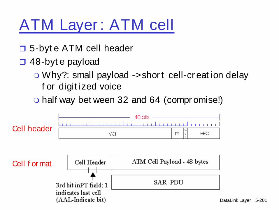
ATM Layer: ATM cellr 5-byte ATM cell headerr 48-byte payloadmWhy?: small payload -> short cell-creation delay
for digitized voicem halfway between 32 and 64 (compromise!)
Cell header
Cell format
5: DataLink Layer 5-202
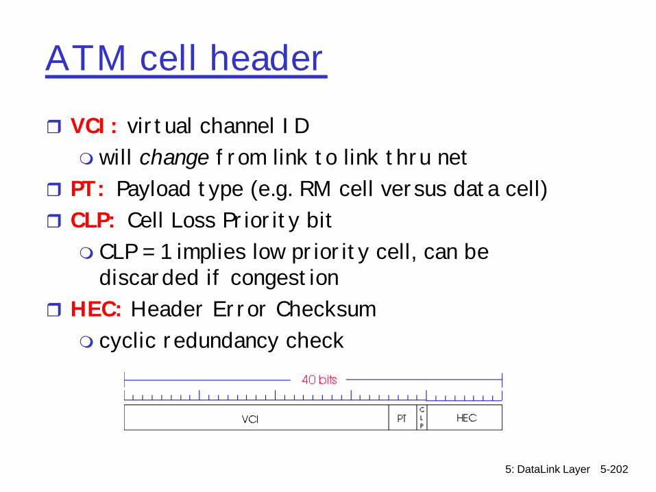
ATM cell headerr VCI: virtual channel IDm will change from link to link thru net
r PT: Payload type (e.g. RM cell versus data cell) r CLP: Cell Loss Priority bitm CLP = 1 implies low priority cell, can be
discarded if congestionr HEC: Header Error Checksumm cyclic redundancy check
5: DataLink Layer 5-203
ATM Physical Layer (more)
Two pieces (sublayers) of physical layer:r Transmission Convergence Sublayer (TCS): adapts
ATM layer above to PMD sublayer belowr Physical Medium Dependent: depends on physical
medium being used
TCS Functions:mHeader checksum generation: 8 bits CRC m Cell delineationmWith “unstructured” PMD sublayer, transmission
of idle cells when no data cells to send
5: DataLink Layer 5-204
ATM Physical Layer
Physical Medium Dependent (PMD) sublayerr SONET/SDH: transmission frame structure (like a
container carrying bits); m bit synchronization; m bandwidth partitions (TDM); m several speeds: OC3 = 155.52 Mbps; OC12 = 622.08
Mbps; OC48 = 2.45 Gbps, OC192 = 9.6 Gbpsr TI/T3: transmission frame structure (old
telephone hierarchy): 1.5 Mbps/ 45 Mbpsr unstructured: just cells (busy/idle)
5: DataLink Layer 5-205
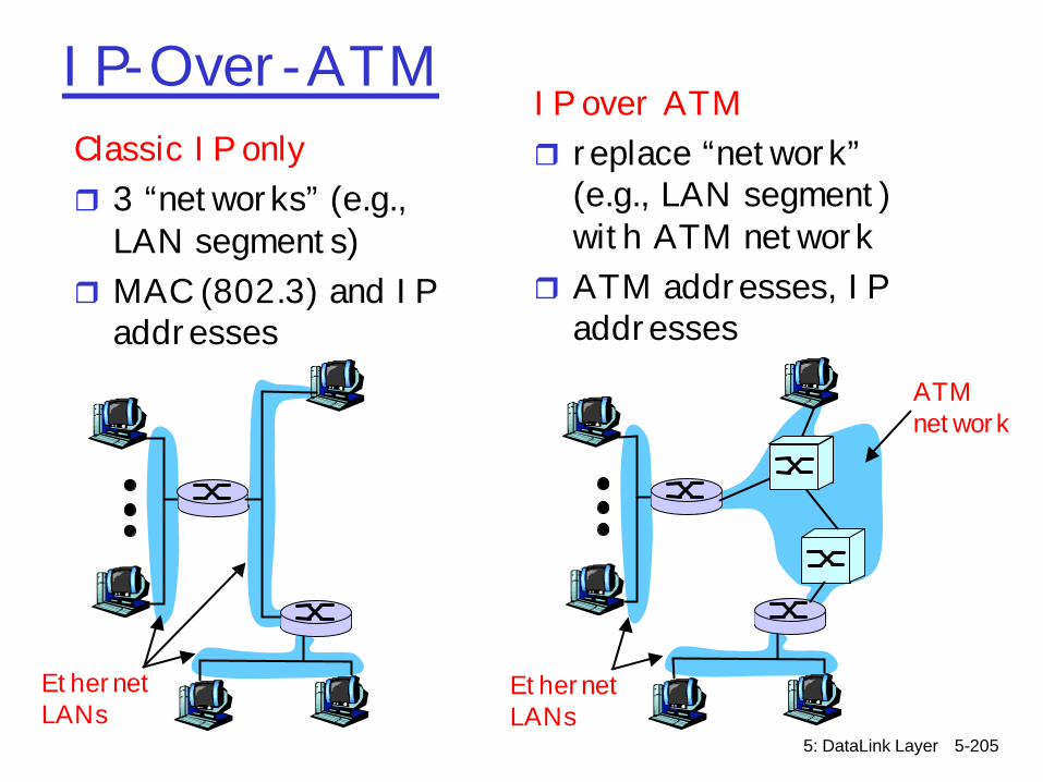
IP-Over-ATMClassic IP onlyr 3 “networks” (e.g.,
LAN segments)r MAC (802.3) and IP
addresses
IP over ATMr replace “network”
(e.g., LAN segment) with ATM network
r ATM addresses, IP addresses
ATMnetwork
EthernetLANs
EthernetLANs

5: DataLink Layer 5-206
IP-Over-ATM
AALATMphyphy
EthIP
ATMphy
ATMphy
apptransport
IPAALATMphy
apptransport
IPEthphy

5: DataLink Layer 5-207
Datagram Journey in IP-over-ATM Network
r at Source Host:m IP layer maps between IP, ATM dest address (using ARP)m passes datagram to AAL5m AAL5 encapsulates data, segments cells, passes to ATM layer
r ATM network: moves cell along VC to destinationr at Destination Host:m AAL5 reassembles cells into original datagramm if CRC OK, datagram is passed to IP
5: DataLink Layer 5-208
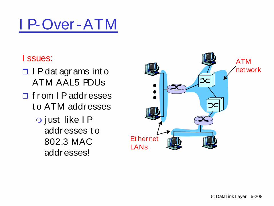
IP-Over-ATM
Issues:r IP datagrams into
ATM AAL5 PDUsr from IP addresses
to ATM addressesm just like IP
addresses to 802.3 MAC addresses!
ATMnetwork
EthernetLANs

5: DataLink Layer 5-209
ATM and “IP switching”r ATM advantages
m Lookup of VCID = O(1), Lookup of IP routes O(log n)m One-time route lookup and circuit establishment, all
subsequent traffic switchedr ATM disadvantages
m Complex signaling and routing for establishing communication
m Difficulty in mapping IP traffic dynamically onto ATM circuits
r Goalm Maintain IP infrastructurem Accelerate it with labels to support O(1) lookups a la
ATMr Solution
m Ipsilon and “IP switching”m http://pnewman.org/papers/infocom96.pdf

5: DataLink Layer 5-210
IP over ATM versus IP switching
IP network controlIP routing
ATM network controlATM label switching
IP network control IP routing
IP network control IP routing
IP network controlATM label switching
IP network controlIP routing
5: DataLink Layer 5-211
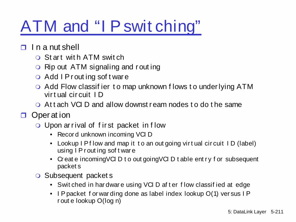
ATM and “IP switching”r In a nutshell
m Start with ATM switchm Rip out ATM signaling and routingm Add IP routing softwarem Add Flow classifier to map unknown flows to underlying ATM
virtual circuit IDm Attach VCID and allow downstream nodes to do the same
r Operationm Upon arrival of first packet in flow
• Record unknown incoming VCID• Lookup IP flow and map it to an outgoing virtual circuit ID (label)
using IP routing software• Create incomingVCID to outgoingVCID table entry for subsequent
packetsm Subsequent packets
• Switched in hardware using VCID after flow classified at edge• IP packet forwarding done as label index lookup O(1) versus IP
route lookup O(log n)
5: DataLink Layer 5-212
ATM and “IP switching”
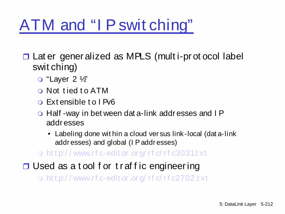
r Later generalized as MPLS (multi-protocol label switching)m “Layer 2 ½”m Not tied to ATMm Extensible to IPv6m Half-way in between data-link addresses and IP
addresses• Labeling done within a cloud versus link-local (data-link
addresses) and global (IP addresses)m http://www.rfc-editor.org/rfc/rfc3031.txt
r Used as a tool for traffic engineeringm http://www.rfc-editor.org/rfc/rfc2702.txt