chapter 4—design elements, considerations, and toolschapter 4—design elements, considerations,...
TRANSCRIPT

4—1
Chapter 4—Design Elements, Considerations, and Tools
Good low-water crossing design is a challenge because the objectives are to produce a structure that meets traffic needs, maintains the natural channel function, passes aquatic species, and is both safe and cost effective. Although each objective may be easy to achieve independently, some objectives can conflict, making it difficult to achieve all objectives at the same time. Poor site selection or choosing an inappropriate structure for a given site can exacerbate the problem. Like most hydraulic structures, low-water crossings require attention to both design detail, and compatibility with the hydrologic and natural setting into which the structure will go.
Acknowledging Risk Low-water crossings inevitably involve some risk in several aspects of the selection and design process because they may allow people to drive through water, and because sites are commonly in rural areas with limited site and hydrologic information. The following risk factors must be taken into consideration when using low-water crossings:
■ Danger when people choose to drive through flooded fords.
■ Occasional traffic delays during flooding making road use more restricted than anticipated.
■ Exceeding the design flow, although fords are less sensitive to this factor than culverts or bridges.
■ Possibility of damage to—and failure of—a structure, depending upon the type of structure selected, the scour protection used, riprap size chosen, etc.
■ Environmental damage if the structure does not perform well.
Although difficult to quantify, each risk can be kept at an acceptable level by applying thorough engineering design and good judgment, using good and suitable materials, and using an interdisciplinary process. Examining existing or current structures that are (or are not) performing well and taking a broad view of the stream and its function can significantly improve project judgment and help reduce the risk of problems. Low-water crossings can be very cost effective structures when the attendant risks are controlled and minimized.
If safety risks are determined to be unacceptably high, choose a different type of structure, such as a large culvert or bridge. On low-volume roads, the advantages of low-water crossings can outweigh their risks because traffic is low, speeds are slow, and a failed ford will likely cause less damage and cost less to replace than a failed culvert or bridge.

4—2
Low-Water Crossings
4.1 Overview of Key Engineering Design Elements
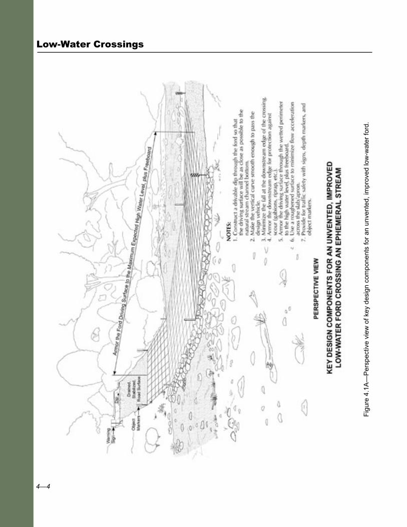
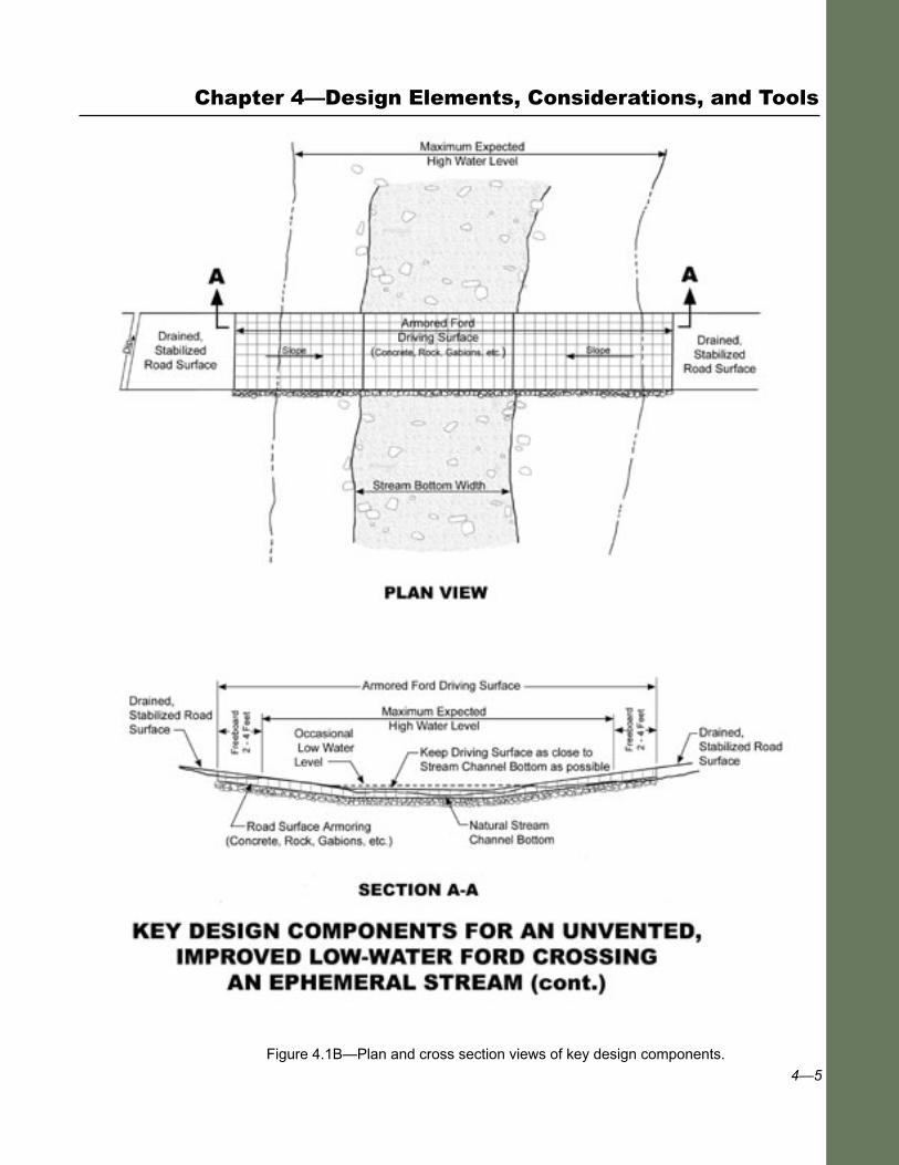
Key design elements of a low-water crossing, as identified in figures 4.1A and 4.1B, include the following:
■ Accommodating traffic and passing the design vehicle safely.
■ Planning for acceptable traffic delays with selection of appropriate low-flow and high-flow values.
■ Ensuring the structure conforms to the site’s shape, is as low as possible, and minimizes site disturbance and channel blockage.
■ Ensuring passage for aquatic organisms, when appropriate, by considering potential obstacles from structure height, changes in flow depth, or accelerated flow velocities.
■ Maintaining the stability of the channel and banks by preventing scour around and beneath the structure, or by preventing bank erosion, sediment deposition, and potential changes in bedload size and quantity (i.e., maintaining channel form and function).
■ Providing structure stability, including driving surface, elevated slabs, footings, approaches, and necessary armoring which prevents damage and minimizes maintenance.
■ Armoring the structure’s entire wetted perimeter, plus freeboard.
■ Providing for traffic safety with warning signs, depth and object markers, curbs, etc.
■ Disconnecting the road from the stream with appropriate surface drainage and roadway stabilization measures.
Poor structure design and site incompatibility can cause a variety of problems, including the following:
■ Causing unreasonable traffic delays or difficulty turning around during flooding.
■ Narrowing the channel, with resultant increase in flow velocity and scour.
■ Damming the channel. (A relatively high structure can cause upstream sediment deposition and downstream scour or degradation, thereby changing the channel’s shape).
■ Restricting or blocking passage of fish or other aquatic organisms, as a result of high velocities and excessively high waterfalls.

4—3
■ Interrupting floodwater access to the flood plain adjacent to the active stream channel.
■ Causing premature structure failure.
■ Accidents and injury.
The USDA Forest Service and other agencies have built many low-water crossings over the past 40 years. Many have worked and many have failed. Most have required some maintenance or improvement to become the functioning structures seen today (see appendix A, case studies). Although functioning from an engineering and road-use standpoint, many low-water crossings are creating stream channel changes, accelerated maintenance needs, and fish barriers. The aquatic, geomorphic, and design perspectives that follow will help interdisciplinary teams design structures to serve road-user needs, minimize long-term costs, and protect the stream environment. Because many sites require considerable experience and judgment for proper structure selection and design, all information in this chapter is based on both standard engineering road design practices and the experience and judgment of the authors.
To accomplish the design objectives of a low-water crossing and have the crossing function well, it is important to evaluate and incorporate several fundamental elements involving channel, hydrologic, hydraulic, fisheries, and engineering considerations. Subsequent sections address these elements in detail. Table 4.1 summarizes these elements and their associated issues, as outlined below:
■ Structure-Site Compatibility.
■ Fish and Aquatic Organism Passage.
■ Roadway and Site Geometry.
■ Site Hydrology.
■ Hydraulic Design.
■ Scour, Bank Protection, and Preventing Channel Changes.
■ Structural Design of the Driving Surface.
■ Traffic Control and Safety.
■ Materials Selection.
■ Best Management Practices for Erosion Control and Water Quality Protection.
Chapter 4—Design Elements, Considerations, and Tools
4—4
Low-Water Crossings
Fig
ure
4.1A
—P
ersp
ectiv
e vi
ew o
f key
des
ign
com
pone
nts
for
an u
nven
ted,
impr
oved
low
-wat
er fo
rd.
4—5
Chapter 4—Design Elements, Considerations, and Tools
Figure 4.1B—Plan and cross section views of key design components.
4—6
Low-Water Crossings
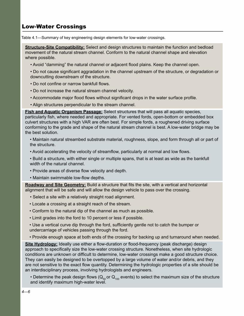
Table 4.1—Summary of key engineering design elements for low-water crossings.
Structure-Site Compatibility: Select and design structures to maintain the function and bedload movement of the natural stream channel. Conform to the natural channel shape and elevation where possible.
• Avoid “damming” the natural channel or adjacent flood plains. Keep the channel open.
• Do not cause significant aggradation in the channel upstream of the structure, or degradation or downcutting downstream of the structure.
• Do not confine or narrow bankfull flows.
• Do not increase the natural stream channel velocity.
• Accommodate major flood flows without significant drops in the water surface profile.
• Align structures perpendicular to the stream channel.
Fish and Aquatic Organism Passage: Select structures that will pass all aquatic species, particularly fish, where needed and appropriate. For vented fords, open-bottom or embedded box culvert structures with a high VAR are often best. For simple fords, a roughened driving surface conforming to the grade and shape of the natural stream channel is best. A low-water bridge may be the best solution.
• Maintain natural streambed substrate material, roughness, slope, and form through all or part of the structure.
• Avoid accelerating the velocity of streamflow, particularly at normal and low flows.
• Build a structure, with either single or multiple spans, that is at least as wide as the bankfull width of the natural channel.
• Provide areas of diverse flow velocity and depth.
• Maintain swimmable low-flow depths.
Roadway and Site Geometry: Build a structure that fits the site, with a vertical and horizontal alignment that will be safe and will allow the design vehicle to pass over the crossing.
• Select a site with a relatively straight road alignment.
• Locate a crossing at a straight reach of the stream.
• Conform to the natural dip of the channel as much as possible.
• Limit grades into the ford to 10 percent or less if possible.
• Use a vertical curve dip through the ford, sufficiently gentle not to catch the bumper or undercarriage of vehicles passing through the ford.
• Provide enough space at both ends of the crossing for backing up and turnaround when needed.
Site Hydrology: Ideally use either a flow-duration or flood-frequency (peak discharge) design approach to specifically size the low-water crossing structure. Nonetheless, when site hydrologic conditions are unknown or difficult to determine, low-water crossings make a good structure choice. They can easily be designed to be overtopped by a large volume of water and/or debris, and they are not sensitive to the exact flow quantity. Determining the hydrologic properties of a site should be an interdisciplinary process, involving hydrologists and engineers.
• Determine the peak design flows (Q50
or Q100
events) to select the maximum size of the structure and identify maximum high-water level.

4—7
• Determine low-flow information (baseflow to Q2, or bankfull flow) to size the vents in a structure,
and estimate the frequency of probable delays.
• Quantify flows suitable for fish passage through structure or vents.
• Estimate traffic-delay times using either flow-duration data or field knowledge of the site.
Hydraulic Design: Determine the site hydraulic factors needed for prudent structure design.
• Determine flow capacity through vents and over the structure, up to the high water elevation.
• Use computer models, Manning’s Equation, pipe capacity nomograms, or broadcrested weir formulas to determine flow through and over respective components of the ford.
• Determine stream velocities (through the structure) that will require riprap or other scour protection measures.
• Limit velocities to those suitable for needed fish passage.
Scour, Bank Protection, and Preventing Channel Changes:¨Protect the channel, the structure, and its foundation against scour and erosion.
• Prevent accelerated stream flows that can damage structures, wash out the approaches, or provide a source of sediment into the watercourse.
• Prevent a “waterfall” and other scour-critical areas by keeping structures low to the channel and by avoiding channel constriction and mid-channel structures or obstructions.
• Install scour protection or energy dissipation measures, including rock riprap, concrete aprons and cutoff walls, gabion basket aprons, or plunge pools.
• Protect streambanks with vegetation, biotechnical measures, erosion control or reinforcing mats, gabions, concrete blocks, rock riprap, etc.
• When riprap is used, size and place the rock to prevent rock movement resulting from the velocity and force of water.
Structural Design of Driving Surface: Design low-water crossings to support the design vehicle for the onsite soil conditions.
• Unless otherwise indicated, design all elevated structures (slabs, box culverts, or pipes) and bridges to support an 80,000 pound, HS-20-44 “legal” design load, in accordance with AASHTO “Standard Specifications for Highway Bridges” requirements.
• Provide at least 1-foot compacted soil cover over culverts, or a concrete slab (typically at least 6 to 8 inches thick) over box culverts, based upon manufacturers’ requirements or structural analysis.
• Construct the roadway driving surface with material durable enough or heavy enough to resist the shear stresses or lateral forces of the water flow.
• Protect the entire “wetted perimeter” of the ford (the area of the entire high flow), plus freeboard (typically 2 to 4 feet of additional height).
• Remove soft or organic subgrade soils and replace the soil with select, structurally sound material in a layer thick enough that will support the traffic without deformation.
Chapter 4—Design Elements, Considerations, and Tools
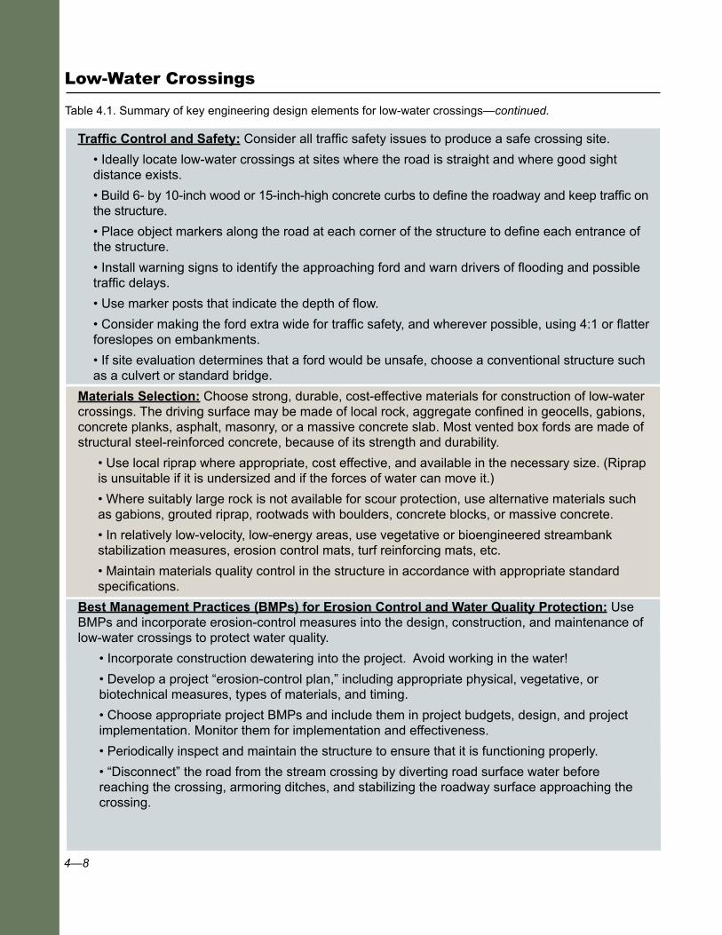
Table 4.1—Summary of key engineering design elements for low-water crossings—continued.
4—8
Low-Water Crossings
Traffic Control and Safety: Consider all traffic safety issues to produce a safe crossing site.
• Ideally locate low-water crossings at sites where the road is straight and where good sight distance exists.
• Build 6- by 10-inch wood or 15-inch-high concrete curbs to define the roadway and keep traffic on the structure.
• Place object markers along the road at each corner of the structure to define each entrance of the structure.
• Install warning signs to identify the approaching ford and warn drivers of flooding and possible traffic delays.
• Use marker posts that indicate the depth of flow.
• Consider making the ford extra wide for traffic safety, and wherever possible, using 4:1 or flatter foreslopes on embankments.
• If site evaluation determines that a ford would be unsafe, choose a conventional structure such as a culvert or standard bridge.
Materials Selection: Choose strong, durable, cost-effective materials for construction of low-water crossings. The driving surface may be made of local rock, aggregate confined in geocells, gabions, concrete planks, asphalt, masonry, or a massive concrete slab. Most vented box fords are made of structural steel-reinforced concrete, because of its strength and durability.
• Use local riprap where appropriate, cost effective, and available in the necessary size. (Riprap is unsuitable if it is undersized and if the forces of water can move it.)
• Where suitably large rock is not available for scour protection, use alternative materials such as gabions, grouted riprap, rootwads with boulders, concrete blocks, or massive concrete.
• In relatively low-velocity, low-energy areas, use vegetative or bioengineered streambank stabilization measures, erosion control mats, turf reinforcing mats, etc.
• Maintain materials quality control in the structure in accordance with appropriate standard specifications.
Best Management Practices (BMPs) for Erosion Control and Water Quality Protection: Use BMPs and incorporate erosion-control measures into the design, construction, and maintenance of low-water crossings to protect water quality.
• Incorporate construction dewatering into the project. Avoid working in the water!
• Develop a project “erosion-control plan,” including appropriate physical, vegetative, or biotechnical measures, types of materials, and timing.
• Choose appropriate project BMPs and include them in project budgets, design, and project implementation. Monitor them for implementation and effectiveness.
• Periodically inspect and maintain the structure to ensure that it is functioning properly.
• “Disconnect” the road from the stream crossing by diverting road surface water before reaching the crossing, armoring ditches, and stabilizing the roadway surface approaching the crossing.
Table 4.1. Summary of key engineering design elements for low-water crossings—continued.
4—9
Key Design Reference Documents This document only summarizes key information on low-water crossing
design. When designing a project, use the following basic references for more detailed information.
■ Lohnes, R. A.; Gu, R. R.; McDonald, T.; Jha, M. K. 2001. Low-water stream crossings: design and construction recommendations. Final Report CTRE Project 01-78, IOWA DOT Project TR-453. Ames, IA: Iowa State University, Center for Transportation Research and Education (http://www.ctre.iastate.edu/).
■ Gu, R. R.; Waugh, J.; Lohnes, R. A. [and others]. 2005. Low-water crossing study: design approach. FHWA-CFL/TD-05-013. Lakewood, CO: U.S. Department of Transportation, Central Federal Lands Highway Division. 136 p. Vol. II. (also see Volume I, Literature Review).
■ Motayed, A. K.; Chang, F. M.; Mukherjee, D. K. 1982. Design and construction of low-water stream crossings. Report No. FHWA/RD-82/163. June. Washington, DC: U.S. Department of Transportation, Federal Highway Administration.
4.2 Structure-Site Compatibility and Crossing Location
4.2.1 Structure-Site Compatibility
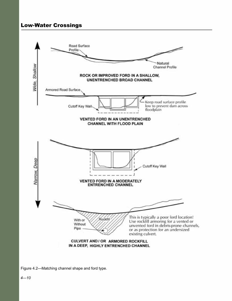
Numerous factors must be taken into consideration when fitting a structure to a specific site (review table 3.3). To be compatible with its site, a structure should preserve channel function as well as providing for safe traffic use. The structure should conform to the site as shown in figure 4.2. Broad, shallow (slightly entrenched) channels are the ideal shape for unvented fords. Slightly to moderately entrenched channels can be well-suited for crossings with vented fords. Deep, entrenched channels are typically least suited for fords, but in special circumstances rock-fill fords and vented fords are appropriate crossings even in these channels. For examples, see case studies 3 and 16.
Structure-site compatibility includes the following elements:
■ The structure should conform to the shape and channel capacity of the natural channel.
■ The structure should not form a “dam” across the channel.
Chapter 4—Design Elements, Considerations, and Tools
4—10
Low-Water Crossings
Figure 4.2—Matching channel shape and ford type.

4—11
Chapter 4—Design Elements, Considerations, and Tools
■ The structure should have a high percentage of open area or a high VAR across the channel (see fig. 1.4.).
■ The structure should prevent or minimize the acceleration of flow velocities through the structure.
■ Approaches to the structure should not dam the flood plain where substantial overbank flow occurs.
■ The structure should cross perpendicular to the channel to minimize the disturbance area and reduce costs.
■ The structure must safely pass the anticipated vehicles, as well as fit the site.
Structures maintain channel function by accommodating channel dynamics, shape, slope, and site characteristics. Streams move mass and energy along the channel and through the flood plain. A properly functioning channel can transport its natural volume of water and sediment, maintain lateral and vertical stability (without excessive scour or deposition), and preserve the channel’s width-to-depth ratio. Because completely matching structure to channel dimensions or roughness is impossible, mitigation measures are often necessary, particularly for protection against accelerated velocities. Section 4.7 (Scour, Bank Protection, and Preventing Channel Changes) addresses commonly used mitigation measures.
A structure usually needs a maximum capacity adequate to pass the design flow (Q
50 to Q
100) within its armored cross section. Flows exceeding
channel or structure capacity will spill over or around the structure, or onto an adjacent flood plain. Narrowing the channel focuses flow through the structure at a greater velocity and increases downstream scour potential and bank erosion. Structures with a low VAR, such as vented fords with small culvert pipes, are most likely to create a decreased channel capacity, a damming effect, and cause upstream deposition. Accelerated velocities through the culvert pipes usually cause downstream scour. As a result, mitigation measures such as channel armoring, stilling basins, or other energy dissipators become necessary.
On deeply entrenched steep channels, the channel will contain the flow, but the road needs protection from the high stream energy, and debris passage must be available. Small bridges are commonly used, particularly if aquatic passage is required. Where aquatic passage is not an issue, however, well-armored rock-fill fords and vented fords have been used successfully on these channels (case study 3), particularly where the channel is prone to debris flows.
4—12
Low-Water Crossings
In slightly entrenched channels (fig. 2.1d) flood flows often overtop the channel and flow across a flood plain. To avoid damming the flood plain in this setting, keep roadway fill approaches to fords low and flat, reflecting the shape of the natural topography. Ideally, the roadway should be overexcavated, backfilled with structurally sound material, and kept at the flood plain elevation. These actions help disperse flows across the flood plain, reducing the chance of concentrated return flows that cause bank erosion. If the roadway must be raised, make sure it has periodic dips or relief culverts across the road for distributing the flood flows. Figure 3.2 shows upstream deposition and downstream scour from a long, elevated low-VAR ford across an unconfined, dynamic channel in Arizona. In this case, the channel and part of the flood plain were dammed, causing channel widening and shifting upstream.
The Jones Wreckum low-water bridge (case study 21) is an example of a structure compatible with its site. The bridge is located immediately upstream of a 90-degree bend in the channel with a gravel point bar on the inside of the bend. Bridge designers appropriately treated this point bar as part of the active channel and spanned it. Debris accumulated under the bridge has increased sediment deposition on the point bar, but channel form is substantially the same as when the bridge was built.
Knowledge of the local stream system and the road needs is necessary to properly assess structure-site compatibility. Field data should include stream channel profiles extending far enough upstream and downstream from the crossing to show whether the natural channel is stable, aggrading, or degrading. Channel cross sections should also be surveyed, and they should be wide enough to cover the possible extent of high water on the flood plain. The cross sections best show how a certain type of low-water crossing will conform to the shape of the natural stream channel. The Hydraulic Structure—Initial Site Examination Form in appendix B is a useful checklist of items to examine in the field and a good tool for documenting channel and other site characteristics. The form includes enough site information to make preliminary design decisions. In addition to the form, all sites should have a site sketch and accurate surveys of channel longitudinal profile and cross sections. Difficult or complicated sites should receive a more indepth investigation.
The longitudinal profile in conjunction with the cross sections will show how the stream has adjusted to the existing structure. It is common to see some sediment accumulation upstream and scour downstream. Using stable grade controls as endpoints, it is possible to project the slope and elevation of the streambed through the crossing, as if no structure were there. That will be the design streambed elevation through the crossing
4—13
(the profile to which the stream will adjust after the new structure is built) unless the goal is for the new structure to control streambed elevation. If the new structure is to function as a grade control, use the longitudinal profile when selecting the elevation to avoid modifying stream slope and sediment transport processes as much as possible.
Similarly, the cross sections will show channel adjustment (usually widening, deposition, and scour) around the existing structure. They can help assess the volume of sediment that might be mobilized after the structure is removed. It may be necessary to remove some accumulated sediment during construction to prevent it from affecting downstream habitats.
If new structure objectives include preserving or reestablishing stream continuity for the purpose of AOP, it will be necessary to take some cross sections outside the area influenced by any existing structure—some distance upstream or downstream from the structure. Ideally, the cross sections would be taken in a reference reach (an undisturbed reach representing natural channel form and slope) near the crossing site. The reference reach cross sections can be used to determine channel width and depth through the crossing, and to design bank reconstruction or other channel restoration elements.
Observe how mobile the streambed materials are. Streambeds composed of loose gravels and finer materials are usually very mobile; that is, sediment moves frequently and the channel will adjust rapidly to a new structure. Depending on slope, rock size, and channel stability, cobble-boulder streambeds may not change much until a large runoff event occurs. The longitudinal profile and cross sections will help with this evaluation, by showing the degree of adjustment to the existing structure. Channels with more mobile materials generally show larger responses to structures that partially interrupt sediment transport.
Streambed material size and mobility affect scour potential and depth around structures. They also affect the decision to backfill an embedded structure such as a box culvert or allow it to fill naturally. Embedding a structure without backfilling it to streambed elevation creates a steep drop, causing the upstream streambed to erode (headcut) until the hole fills and the slope equilibrates. The effect of this erosion on the upstream channel depends in part on how much sediment is available and how mobile it is. If the streambed is mobile, the structure will probably fill rapidly under moderate flows and the stream may not be noticeably affected. If bed material is immobile (i.e., does not move until fairly large flows) little sediment will be available immediately. The structure should probably
Chapter 4—Design Elements, Considerations, and Tools
4—14
Low-Water Crossings
be filled during construction to avoid destabilizing the upstream bed. If it is not filled, a headcut may move upstream, lowering the streambed elevation. The degradation may detrimentally affect bank stability, habitats, buried infrastructure, etc.
Another item to assess is the quantity and size of debris moving through the system. Some small sediment and debris will move through almost any type of structure. If the channel has a lot of mobile sediment and debris, small vents that backwater high flows will tend to plug. Large woody debris can block even large vents. Because they have an open cross section, simple unvented fords are ideal for crossing drainages carrying a lot of debris.
Vented fords and low-water bridges have problems with debris plugging, but are designed to sustain plugging without failing and can still pass additional debris over the top. Trapped debris does require periodic cleaning.
4.2.2 Crossing Location
The ideal crossing location is straight, stable, moderately broad, and moderately entrenched. When channel bed and banks are stable and have firm structural materials, road crossings are least likely to encounter difficulties with changes in channel form, such as widening or incising. Ideal locations include bedrock-controlled channels and those with a rocky bed and banks. Compared to slightly entrenched channels, moderately entrenched channels are also less likely to overflow, outflank the structure, and cause road damage (see section 2.2).
Poor locations for fords include channels with structurally soft bed or banks such as are often found in wide alluvial (meadow) valleys, meander bends, unstable, unconfined reaches or braided channels, and settings with rapid slope change, such as from a mountain to a valley stream where deposition occurs. Alluvial fans are particularly poor locations because they can be very unstable.
Study these sites in detail to ensure the structure and road geometry fit the channel. Protect the channel against local scour and properly key the structure in place. Placing a structure in a poor location usually leads to relatively expensive designs with higher protection and maintenance costs. Simple unimproved fords may be most practical in poor locations because they require minimum investment if the crossing is destroyed in a flood.
4—15
Chapter 4—Design Elements, Considerations, and Tools
A history of structure or channel problems at a site suggests the need to relocate the crossing. Regardless of aquatic resource, structure, and channel impacts, however, features such as other existing infrastructure, archeological sites, rights-of-way, or high moving costs may dictate the crossing remain in its current location. In these situations, maintenance and repair costs, as well as environmental impacts, are likely to remain high.
4.3 Fish and Aquatic Organism Passage
Why do aquatic organisms need to be able to move freely through road crossings? Even where animals do not “migrate,” they still need to move to find
food, mates, better water quality, or simply to disperse. Local habitat characteristics change over time as weather and flow vary, and aquatic animals move at various times to escape poor conditions or seek better ones. Even ephemeral and intermittent streams often support fish and other aquatic species for part of the year. For example, during snowmelt runoff, side channels and intermittent tributaries may provide refuge from high, turbulent flow in the mainstream river. Headwater streams not supporting fish may provide excellent amphibian habitat, and the juvenile lifestages of many amphibians are completely aquatic (Jackson 2003). Even adult lifestages of some species may be unable to move over a dry surface. Due to the many different species potentially involved and their different movement needs, a biologist should determine the need for passage at any specific site.
Where passage for all aquatic organisms is desired, streambed continuity through the crossing should be maintained. Although stream simulation is a crossing design technique usually applied to culverts, it can also be applied to bridges and some crossings designed to sustain overtopping. Stream simulation structures are large enough to enable the channel to maintain characteristics like width, depth, slope, and streambed roughness through the crossing. Areas of diverse water velocity and depth are therefore available through the structure just as they are in the natural channel. The structure is at least as wide as the natural bankfull cross section so that it neither widens nor constricts flow, and

4—16
Low-Water Crossings
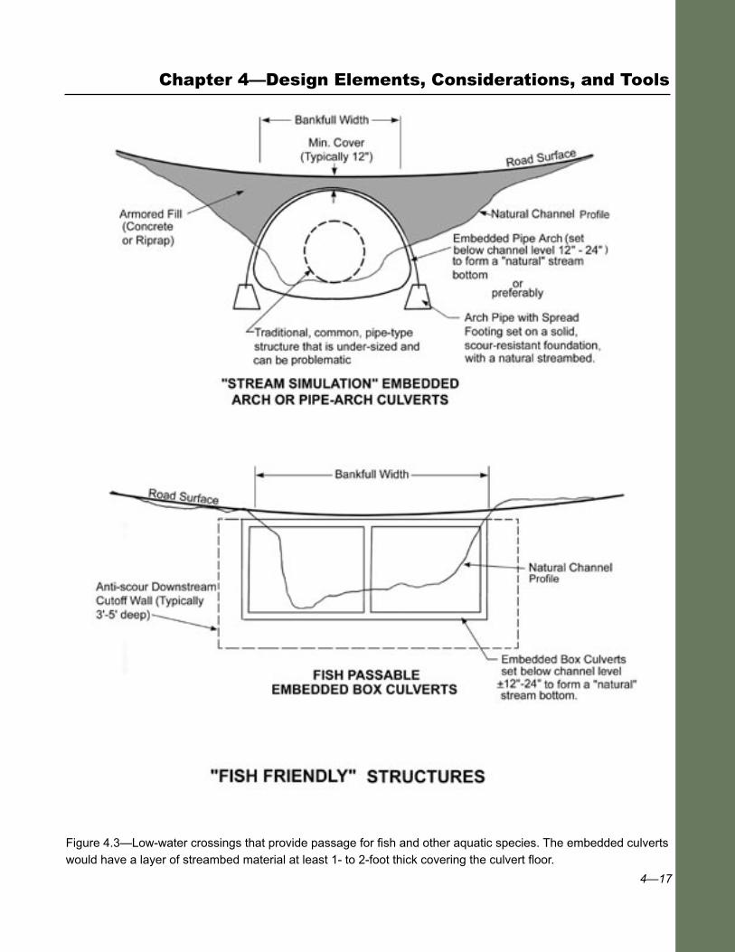
it provides margins for crawling species most of the year. Fish passage is accommodated at low flows and at most flow levels. Aquatic organisms should be able to pass during their normal migration periods. In most cases, stream simulation culverts or bridges are also large enough to pass most materials moving downstream even during floods. Nevertheless, in streams with heavy debris, ice, or bed material loads that might plug the structure, they can be designed to overtop (fig. 4.3).
One low-water crossing style that is used increasingly where aquatic species and habitat protection are important is a series of embedded box culverts that look and perform like a bridge. Crossings described in case studies 17, 18, 19, 20, and 21 appear to provide full passage for most swimming species, if not all aquatic species. The structures are either low-water bridges or embedded box culverts with continuous streambed material through the structure. Some pass the 25-year flood under the deck; others are submerged by bankfull flow. The one characteristic these structures have in common is that they match—or nearly match—channel width. We do not know how stable the streambeds are inside these structures during large floods. If they do wash out, however, they refill with sediment as flow recedes or during later more moderate flows.
Unvented at-grade fords can also be designed for passage of many aquatic species by keeping streambed materials nearly continuous across the driving surface. The ford at Fitzpatrick Creek on the Coos Bay BLM district uses cable concrete mats at a site where debris jams had washed out very large culverts and their fills several times (case study 6). The mats enable streambed material deposition between the blocks, and appear to have sufficient surface roughness so flow velocities remain low enough for juvenile salmon passage at low flows. The availability of full passage for all aquatic organisms is unknown. In some situations, an at-grade ford with a simple rock and gravel driving surface can also provide adequate fish passage (case study 2). Similarly, geocell structures infilled with aggregate, such as those on the Bighorn, Ashley, and Humboldt-Toiyabe National Forests, provide some degree of fish passage (case study 7). When animals and traffic are present at the same time, however, the tradeoffs at an unvented ford call for serious consideration, because some animal mortality is likely. To minimize the impacts to the fish, additional limitations on road use might be considered during spawning periods.
Designers have used some creative techniques to achieve fish passage over concrete floors or slabs (case study 14). Key hydraulic design considerations for passage of any swimming species are water depth, velocity, resting areas, and drops or plunges. The combination of surface roughness and slope is important for maintaining swimmable depths and velocities. For example, some unembedded box culverts (case study 13)
4—17
Figure 4.3—Low-water crossings that provide passage for fish and other aquatic species. The embedded culverts would have a layer of streambed material at least 1- to 2-foot thick covering the culvert floor.
Chapter 4—Design Elements, Considerations, and Tools
4—18
Low-Water Crossings
fail to pass small fish because the concrete box floor, set to match channel slope, is so smooth even extreme low flows are a velocity barrier.
Concrete fords with slots can provide fish passage and keep vehicles out of the water during low flows. The slot design is important for ensuring that velocities and depths are appropriate at low flows, and that the slot does not plug. The Mesman ford (case study 9) works for the following reasons:
■ The slot is designed to meet the velocity and depth criteria for trout at normal low flows.
■ Gravels in transport are small compared to the 4-inch-wide slot, so plugging is not an issue.
■ Riprap placed immediately upstream of the inlet creates an additional protection against small debris plugging.
In contrast, the Grubbs vented ford (case study 12) has a 3-foot-wide slot designed for fish passage. The slot regularly fills with the very mobile boulder-sized rock this channel transports. Fortunately some fish movement has been observed over the structure. Fords constructed of concrete planks, with a 6-inch space between the planks (case study 5), also provide some degree of animal passage when the structure is submerged.
Generally, the closer the structure can imitate and blend in with the adjacent natural stream channel, the better the aquatic species passage.
FishXing is a program that helps designers deal with fish passage issues. A team headed by Michael Furniss, principally funded by USDA Forest Service and U.S. Department of Transportation, Federal Highway Administration, developed FishXing, which is available at http://www.stream.fs.fed.us/fishxing/index.html. FishXing is a hydraulic model that calculates water velocity and depth in a culvert, and then compares them with the swimming capabilities of specific fish species. The model can reveal at what flows fish cannot pass the culvert and what the obstruction is. To find velocity and depth criteria for the target fish and lifestage, review the FishXing help files, or other sources such as Beamish (1978).
FishXing is not designed for slab fords. For slabs, designers can use HEC-RAS, or simply Manning’s equation to determine velocity and depth over the ford (see Section 4.6 Hydraulic Design).
4—19
4.4 Roadway and Site Geometry
Roadway geometry must be adequate for safe passage of the design vehicle. Moreover the road profile should conform to the shape of the natural channel as much as possible. To minimize damming of the channel, any elevated structure should maintain as high a VAR as possible. Low-water crossing structures are designed with a vertical sag, or dip, in the middle of the structure to concentrate overtopping flow to the midchannel, and minimize flow against channel banks. To pass the design vehicle, which may be a log truck, lowboy, or trailer, the vertical curve across the top of the crossing must be broad enough and have a gentle transition to avoid scraping the bumper, trailer hitch, or stinger of the passing vehicle. It may be necessary to control the opening size (box height) of vented fords to help establish the shape and depth of the dip in the roadway surface. Doing so will obviously affect the vent capacity.
4.4.1 Channel Geometry
Ideally, a ford is located on a straight, stable reach of the channel, with the structure crossing perpendicular to the channel to minimize the structure length and maximize sight distance. Angled road approaches may be necessary to fit the terrain or reduce the road grade; however, the design will likely be more difficult, have more site disturbance, cost more, or require additional mitigation measures. Poor alignment may cause or aggravate problems with channel stability. Placing structures with multiple openings on bends should be avoided because the stream usually chooses one opening to carry most flow and the other openings fill with sediment (case study 19). If the structure crosses the channel at an angle that focuses stream energy into the bank, bank erosion and decreased lateral stability will occur. The structure itself, particularly the vents, should be centered on the channel and oriented parallel to the direction of the average bankfull flow.
In slightly entrenched broad shallow channels, fords are often easy to construct, conforming to the natural channel shape. In entrenched deep channels, the dip may be radical with a tight vertical curve, consequently restricting some vehicle passage. Because a raised platform would partially dam the channel, consider a vented ford with a raised roadway platform to accommodate the design vehicle. (Review fig. 2.1 for definition of entrenchment.)
Chapter 4—Design Elements, Considerations, and Tools

4—20
Low-Water Crossings
Some sites, like moderately entrenched channels with locally steep banks, require changes to the channel shape to accommodate a ford. Flattening a streambank requires bank excavation, subsequent channel widening, and possibly mitigation measures for bank stabilization. The widened point decreases flow velocity and increases the possibility of local channel aggradation (case study 7). Road maintenance will probably be necessary after major flows to remove the deposited material.
4.4.2 Roadway Design Geometry
The road width of a ford is typically as wide as the normal roadway width, usually 10 to 12 feet wide at a minimum. On elevated structures, AASHTO “Guidelines for Geometric Design of Very Low-Volume Local Roads” (2001) recommend at least 15 feet for safety reasons. Ideally, the roadway surface should have an outslope of 3 to 5 percent to promote drainage and debris passage during overtopping. If the roadway curves across the drainage, the horizontal curve radius should be a 50-foot minimum to accommodate the turning ability of most vehicles and logging trucks, or a 35-foot minimum for light vehicles. Curved crossings, however, are discouraged due to poor sight distance and safety concerns, particularly in situations where the roadway platform is elevated such as vented fords and low-water bridges.
The design vehicle limits the vertical curve (dip) geometry. Dip geometry is a function of grade into and out of the ford, the vertical-curve length, the depth of the dip, and the wheelbase distance. The most severe limitations often come from chip vans, low boys, trailers, or long recreation vehicles. The AASHTO “Policy on Geometric Design of Highways and Streets” (2001), Chapter 5, and the USDA “Forest Service Handbook (FSH) Preconstruction Handbook, Section 4.3 Alignment” (FSH 7709.56) offer specific guidance for both vertical and horizontal curve design. Where practical, 10 percent is the recommended maximum approach grade. Grades into and out of fords have been in the 15- to 20- percent range (see case study 6, where moderate earthwork was needed), but steep grades require additional stabilization on the approach road to avoid excessive sediment delivery to the creek.
4.5 Site Hydrology
Streamflows are used for several purposes in low-water crossing design. The high design flow determines the maximum expected high water level and the length of roadway that will require surface armoring for scour protection. The high design flow velocity helps determine the necessary
4—21
type of scour protection and riprap size. Duration and volume of low flows, or normal flows, help determine whether a ford is suitable at the site. For vented fords, low flows are also used to determine vent capacity.
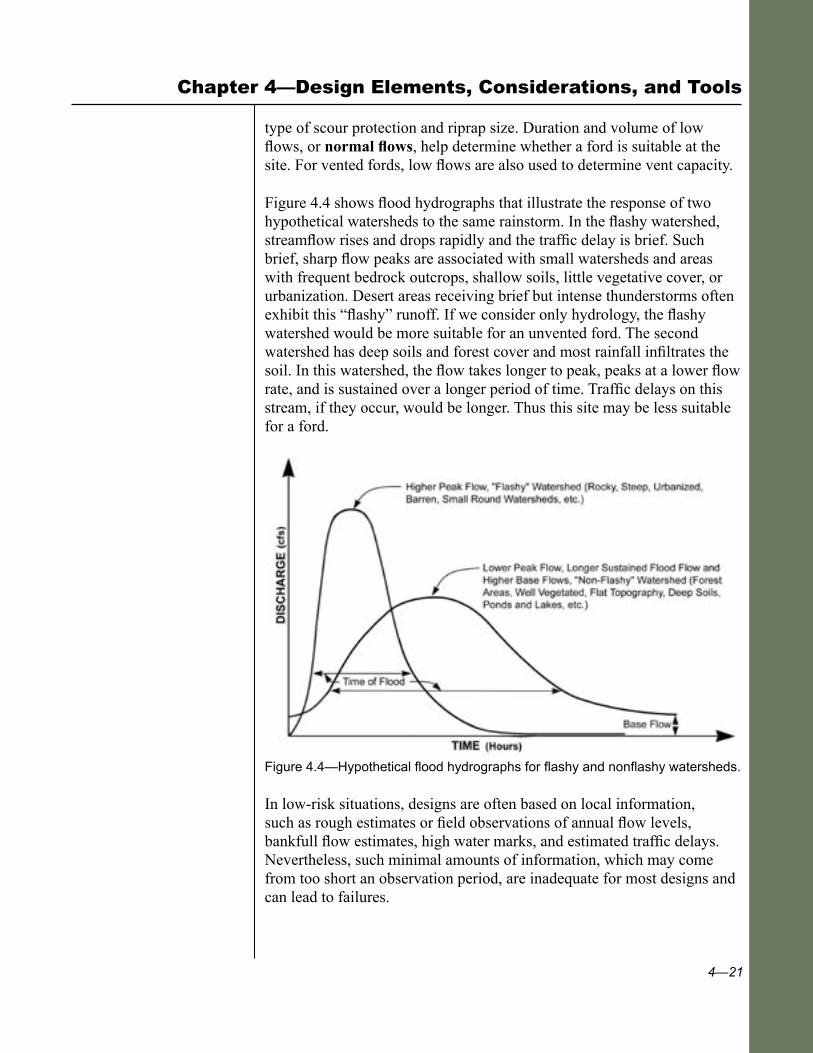
Figure 4.4 shows flood hydrographs that illustrate the response of two hypothetical watersheds to the same rainstorm. In the flashy watershed, streamflow rises and drops rapidly and the traffic delay is brief. Such brief, sharp flow peaks are associated with small watersheds and areas with frequent bedrock outcrops, shallow soils, little vegetative cover, or urbanization. Desert areas receiving brief but intense thunderstorms often exhibit this “flashy” runoff. If we consider only hydrology, the flashy watershed would be more suitable for an unvented ford. The second watershed has deep soils and forest cover and most rainfall infiltrates the soil. In this watershed, the flow takes longer to peak, peaks at a lower flow rate, and is sustained over a longer period of time. Traffic delays on this stream, if they occur, would be longer. Thus this site may be less suitable for a ford.
Figure 4.4—Hypothetical flood hydrographs for flashy and nonflashy watersheds.
In low-risk situations, designs are often based on local information, such as rough estimates or field observations of annual flow levels, bankfull flow estimates, high water marks, and estimated traffic delays. Nevertheless, such minimal amounts of information, which may come from too short an observation period, are inadequate for most designs and can lead to failures.
Chapter 4—Design Elements, Considerations, and Tools
4—22
Low-Water Crossings
Two quantitative approaches should be considered in the hydrologic design of fords. The first approach involves using flow-duration data to estimate the typical annual delay time at a ford and the needed capacity of vents. The second approach involves using (a) flood-frequency data to estimate peak flow values for design of total structure capacity, and (b) local knowledge of low-flow characteristics to determine the type of ford, vent size, and estimate delay times. Because interpretation of flow-duration curves or flood-frequency data can be complicated, we recommend professional help from a hydrologist familiar with the area or watershed.
The more rigorous low-water crossing design approach uses a flow-duration curve developed from daily streamflow data for the specific drainage being crossed. A flow-duration curve based on annual data gives an estimated percentage of time (number of days in the year) that a certain flow will be exceeded. Crossings can be designed so traffic delays occur no more than an acceptable number of days per year. These curves are useful where the total delay time due to structure inundation is important, such as on rural roads accessing communities, homes, or significant public routes. Gu (2003) addresses this design methodology in detail in the recent FHWA publication on Low-Water Crossings.
Figure 4.5 shows a typical annual flow-duration, or exceedence curve. The curve is useful for estimating the time a ford may be impassable and for determining the size or capacity of vents in a ford. Although this data describes the percent of days in a year the road may be impassable, it cannot specify when, how many hours, or how many times per year the delays will occur. Local observations of flow characteristics can help estimate frequency and length of delays.
The simplest, most common approach for designing fords, particularly in the USDA Forest Service, involves using flood-frequency analysis. In this approach, we estimate the peak flow likely to occur or be exceeded every ‘x’ years on average (the recurrence interval for that flow). This method identifies the probability of exceeding different peak flow levels, but does not estimate the timeframe the road may be closed during inundation. Crossings are usually designed so that the armored cross section contains the 50- or 100-year flow.
Use an appropriate high frequency flood, such as a 2 - or 2-year event, to determine vent capacity. A 2 year event (Q2) is a peak flow occurring (on average) twice per year and a 2-year event (Q
2) occurs on average
once every 2 years. The objective would be to keep most traffic out of the water.

4—23
Figure 4.5—Typical flow-duration curve.
The USDA Forest Service most commonly uses the flood-frequency approach in arid areas where high flows are infrequent and of short duration, on roads closed during periods of peak runoff (seasonal road closure), or on roads where infrequent traffic delays do not create problems for users. This approach is very practical because it is possible to estimate peak flows on many small drainages, but reliable flow-duration data will not be available.
As discussed in section 4.3, where fish passage is needed, the ideal way to determine the vent width is to match the channel bankfull width. However, vents can also be designed for fish passage based on hydraulic capacity. In this method, the vent is designed so that fish can swim the length of the culvert at the “fish passage flow.” The fish passage flow is a flow or range of flows that occur when the “design fish” is naturally moving in the channel. It varies for different species, lifestages, and areas, and many States have required standards. When stream simulation is achieved through the structure, specific flows or velocities are not an issue because a natural diversity of conditions exists.
Chapter 4—Design Elements, Considerations, and Tools
4—24
Low-Water Crossings
A variety of methods exist to estimate design flows for either whole-structure capacity or vent capacity. Use more than one method to estimate flows because errors (which can be significant) are inherent in each method. Supplement these methods with information from road maintenance records, old flood photos, field observations, interviews with knowledgeable local residents, and professional judgment.
Excellent summaries of hydrologic design tools for fords and road drainage structures are available in “Highway Hydrology, FHWA Hydraulic Design Series No. 2” (McKuen et al. 2002), and the AASHTO “Highway Drainage Guidelines” (1999). Common flow estimation methods include the following:
■ U.S. Geologic Survey Regression Equations can be found in the National Flood Frequency Program available on the USGS Web site. These equations are based on statistical analysis of existing gauging data and use watershed area, as well as other variables, such as annual precipitation, mean elevation, or watershed latitude. Some areas also have regression equations for bankfull, mean annual, or 7-day low flows for various recurrence intervals. Background information about development and application of the equations, including the users’ manual, is in Ries and Crouse (2002).
■ Computer programs can help determine specific design flows from published rainfall data. Some commonly used programs are: FHWA’s HYDRAIN, the USDA’s Natural Resources Conservation Service TR-20 (now WinTR-20), and the U.S. Army Corps of Engineer’s HEC-1. Reminder: a 50-year rainfall does not necessarily produce a 50-year flow.
■ For small watersheds (under about 300 acres), use simple methods such as the Rational Method, for determining peak flows. The runoff coefficient in this method can be modified to reflect changes in watershed characteristics occurring over time.
■ The slope-area method estimates flow volumes (Q) at any given flow level for which there are high water marks (bankfull, flood flows, etc.) and field observations of channel cross section characteristics and geometry. Determine average flow velocity (V) using Manning’s or other equations, then multiply it by cross-section area to calculate flow volume. For this analysis, use a cross section in a straight, uniform reach outside the crossing’s area of influence.
Numerous hydrology and hydraulics texts and manuals, such as HDS 4 (Schall et al. 2001), explain how to use the Rational Method and
4—25
Manning’s Equation. The program WinXSPRO allows calculation of velocity using Manning’s or other equations for simple or complex cross sections (Hardy et al. 2005). It is available at the USDA Forest Service Stream Systems Technology Center Web site.
Leopold (1994) gives some values to use when making an initial estimate of high water level for 50-year events in various parts of the United States. Very roughly, the data he used showed that the flow depth in a 50-year flood is between 1.4 and 2 times bankfull depth. It is often possible to estimate recent high water levels from field observations of flood-eroded banks, sediment deposits over soils, flood plain swales, and floating debris deposited on the banks and in vegetation.
Understanding design flow depth and volume helps ensure protection of the full wetted perimeter of the ford against the high flow. Add at least 2 feet of additional freeboard to guarantee that high water does not scour around the structure. In broad flood plain areas, armor the ford up to a level where water spreads out across the flood plain. Armor the roadway surface across the entire flood plain area and install cross-drainage.
Because low-water fords are designed to be overtopped, they can usually accommodate very large flows over the structure—plus large amounts of debris—so they are forgiving rather than sensitive to imprecise flow calculations. The “vented” portion of a vented ford has a finite capacity, as do typical culvert installations. Once the structure is overtopped, however, all additional water and debris can flow over the top of the structure. In areas with large flow fluctuations, where the difference between low flow and peak flow is extreme, designing a culvert or bridge capable of handling extreme flows can be either expensive or difficult. Low-water crossings can handle these situations and are especially appropriate in desert environments and ephemeral channels.
4.6 Hydraulic Design
For hydraulic design of a low-water crossing, two or three different calculations are usually necessary to determine the water velocity (V) and flow capacity (Q) of the channel, the entire ford, or through the vents.
Use Manning’s Equation to determine flow capacity through simple unvented fords, as well as flow capacity through low-water bridges where most of the natural channel cross section is open. Use the broad-crested weir formula to determine flow over a raised ford. Select appropriate nomograms and programs from various Federal Highway Administration publications (figs. 4.7 and 4.8) to determine the capacity of pipes or vents,
Chapter 4—Design Elements, Considerations, and Tools
4—26
Low-Water Crossings
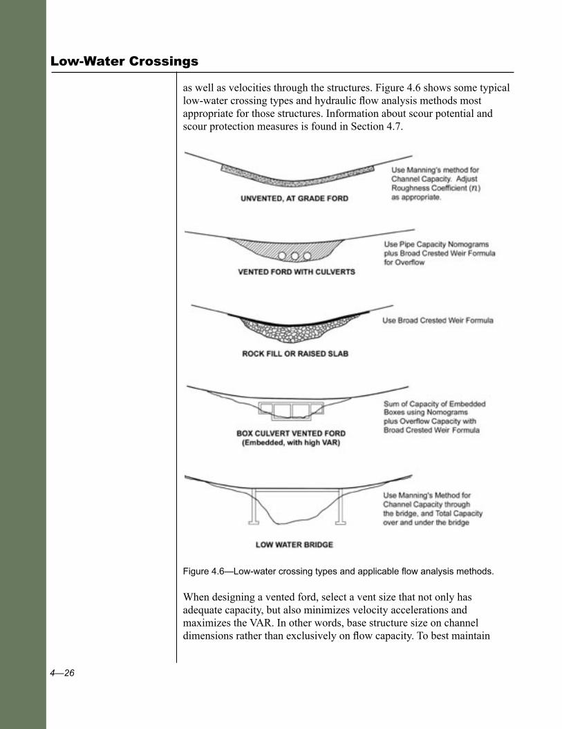
as well as velocities through the structures. Figure 4.6 shows some typical low-water crossing types and hydraulic flow analysis methods most appropriate for those structures. Information about scour potential and scour protection measures is found in Section 4.7.
Figure 4.6—Low-water crossing types and applicable flow analysis methods.
When designing a vented ford, select a vent size that not only has adequate capacity, but also minimizes velocity accelerations and maximizes the VAR. In other words, base structure size on channel dimensions rather than exclusively on flow capacity. To best maintain

4—27
channel function, minimize channel changes, and prevent their associated problems, the opening width should be equal to or larger than the bankfull width (fig. 4.3). This typically results in a very large vent flow capacity.
Flow Capacity As mentioned previously, Manning’s Equation is a very useful tool for determining flow capacity of a natural stream channel or an unimproved ford. In entrenched channels, use Manning’s Equation after obtaining an accurate cross section of the channel and determining the channel slope and roughness characteristics.
In unentrenched channels where part of the flow is across a flood plain, the channel cross section is typically broken into two or more segments to reflect the faster velocities and greater capacity in the main channel and the slower velocities found in the shallower flows (see WinXSPRO program, Hardy et al. 2005). In this case, use Manning’s Equation on each separate part of the channel and add the results to get the total flow. On complicated channels or structures, use programs like the U.S. Army Corps of Engineers HEC-RAS models (USACE 1991) to route water through a varying or complicated reach of the stream. Be aware, however, this program requires extensive field data to produce good results.
Use the broad-crested weir formula to determine the flow capacity over simple unvented fords with a raised roadway driving surface, along with the depth of flow over the raised platform. Use the same formula to estimate the additional flow capacity over vented fords (beyond what goes through the vents). Gu (2005) presents examples of the use of the broad-crested weir formula. Using these formulas requires an iterative process to determine the depth of flow for a given discharge. In these examples, Gu assumes that, for traffic safety, the maximum allowable depth of flow over a weir is 6 inches. The equations in Gu’s examples reflect his design assumptions.
The broad-crested weir formula has limited application on some USDA Forest Service structures because raising the platform of an unvented ford any significant height is generally undesirable. Raising the platform creates both a damming effect and a downstream waterfall, each adversely affecting channel function.
To determine flow capacity through ford vents for round culverts and small box structures in inlet control, use simple design curves for culvert pipe size versus design flow for various entrance conditions (Gu 2005). Alternatively, by using the families of nomograms available in the FHWA publication HDS 5, “Hydraulic Design of Highway Culverts” (Normann, 1985) and the FHWA program HY8 (part of HYDRAIN), flow capacity can be determined for a wide variety of culvert types (round pipes, arches,
Chapter 4—Design Elements, Considerations, and Tools

4—28
Low-Water Crossings
concrete boxes, etc.) for both inlet control and outlet control conditions, as a function of size, entrance type, and headwater depth. The American Iron and Steel Institute’s “Handbook of Steel Drainage and Highway Construction Products” (Fifth Edition 1994) also contains considerable useful information on steel culvert design and installation.
Figures 4.7 and 4.8 present the two HDS-5 nomograms most commonly used to determine capacity versus size for round corrugated metal pipe and concrete box culverts, with various inlet types and for varying headwater depth. These nomograms should be used for inlet control conditions, the condition most often encountered for upland pipe installations. These
Figure 4.7—Corrugated metal pipe capacity nomograph. (Normann, 1985)

4—29
nomograms are strictly for fluid capacity. They are not valid for partially embedded pipes (which have a natural stream bottom for fish passage), nor do they reflect the size needed to pass sediment or debris. Therefore, use local experience and knowledge of the characteristics of the watershed and channel to estimate additional pipe capacity needed for sediment and debris passage
.
Figure 4.8—Concrete box culverts capacity nomograph. (Normann, 1985)
As mentioned in section 4.5, one of the great advantages of fords is their adaptability in conditions where good design flow predictions or local data do not exist, and where there are large amounts of sediment, debris, or
Chapter 4—Design Elements, Considerations, and Tools
4—30
Low-Water Crossings
trash in the channel. Such conditions make determining culvert capacity either very difficult or unrealistic. Although no rational design criteria for debris passage exists, fords are generally able to pass a large flow with a small increase in flow depth over the ford. They can also pass large quantities of debris with minimal damage. Therefore, fords are excellent candidates for sites with these uncertain conditions.
If the channel has significant debris, the vents may periodically plug. Therefore, design to accommodate the entire flow over the structure. Alternatively, increase the size of the vents or use trash racks. If using trash racks, incorporate them into the structure itself at a sloping vent entrance to minimize pipe plugging. The Sibley Creek crossing on the Mount Baker-Snoqualmie National Forest uses a trash rack in this way (case study 16). Trash racks will require periodic cleaning and maintenance.
If an existing culvert is undersized for the anticipated flows, one alternative is to modify it to act like a vented ford by armoring a dip and the fill over the pipe. Although this type of modified structure may not be as effective as a designed ford, it can minimize or prevent site damage or failure from flows overtopping an undersized or plugged pipe.
Flow Velocity In low-water crossing design, it is necessary to estimate average or local velocities for the following reasons:
■ To determine the scour potential and scour depth in parts of the channel.
■ To determine the size of bed material that will move in the channel.
■ To select vegetation, biotechnical measures, riprap, or other armoring adequate in preventing bank erosion.
■ To size rock riprap properly.
■ To determine fish passage limitations or needs.
Bed-material movement is directly related to the shear stress of water flowing against the channel substrate. Some professionals use water velocity in place of shear stress, because velocity is generally an easier parameter to estimate. Nevertheless, local velocities around midchannel piers or obstructions, over waterfalls, cascading over rock-armored slopes, etc., are actually hard to determine, so scour protection measures often rely on model studies or empirical observations.
In natural channels, local flow velocities are highest midchannel and near the surface, and slowest along the banks. However, the average velocity—

4—31
averaged across the entire cross section of flow—is used for most design purposes. Manning’s Equation is most useful for determining average flow velocities in natural or constructed open channels, including embedded or open-bottom culverts where the inlet is not submerged. Velocities can be adjusted across smooth or roughened channel surfaces by modifying the “roughness coefficient” in Manning’s Equation. Programs that calculate streamflow velocities include the U.S. Army Corps of Engineers HEC-RAS, and WinXSPRO, which is available on the USDA Forest Service Stream Systems Technology Center Web site.
Velocities accelerate when flow is confined and forced through a smaller area, such as in a channel constriction. Figure 4.9 shows the pattern of exit flow and velocities from small, constricting pipes as opposed to larger pipes. Traditional small culverts that constrict the channel and accelerate flow velocities can cause bank, fill, and channel scour, both at the pipe inlet and outlet. The higher velocity may also impede or prevent fish passage.
Figure 4.9—Outlet flow patterns and local scour from culverts of different widths.
Chapter 4—Design Elements, Considerations, and Tools

4—32
Low-Water Crossings
When determining exit velocities for pipes or vents, use programs like HY-8, the design charts in the FHWA manual HDS 3 (“Design Charts for Open Channel Flow”) (1961), or simply divide flow volume (cubic feet per second) by the flowing pipe area. For an outlet-controlled pipe flowing full, use the area for that pipe diameter. To determine the area of flow for an inlet-controlled pipe where the pipe is flowing only partially full, find the critical or normal exit flow depth and use it to calculate flow area. To determine critical flow depth, use charts in HDS3 or use a trial-and-error solution of Manning’s Equation.
Pipe exit velocities are often quite high, requiring significant scour protection or energy dissipation, and creating a fish passage barrier. Designing to minimize channel confinement, prevent head buildup over pipes, and maintain flow across roughened or rocky surfaces helps reduce flow velocity. If a ford is built to simulate natural stream conditions (such as matching bankfull width), problems with both channel stability and fish passage will be minimized. Fish passage issues are discussed earlier in sections 3.2 and 4.3. Again, FishXing is a very useful program to evaluate fish passage potential for anticipated flow velocities.
4.7 Scour, Bank Protection, and Preventing Channel Changes
If local or average velocities exceed the permissible velocities of the materials for movement, erosion and scour will result. Therefore, either take measures to reduce the velocities, redirect the flow, dissipate the energy of the flow, provide stability below the likely depth of scour, or armor the areas with various materials that can resist the forces of the flow.
Scour protection and maintaining channel stability—fundamental parts of hydraulic structure design—are particularly important in low-water crossings. Design the crossings to withstand overtopping. Protect or armor the structure to the “wetted perimeter” or the maximum expected high water level, incorporating some additional height for freeboard. In a small drainage, a foot of freeboard may be adequate. In large drainages or steep canyons an additional 2 to 4 feet of freeboard is desirable. Different types of fords create different scour risks; for example some accelerate flows through pipes or vents, some confine channel flow, some accelerate flow across the driving surface, and some create a water drop off the downstream edge. These areas commonly need protection.

4—33
Depending on the velocity of flow, erosion, scour protection, and bank stabilization come in many of the following forms:
■ Vegetation, erosion control mats, or small riprap for low velocities.
■ Soft-armor systems, such as biotechnical treatments, vegetated turf reinforcing mats, rootwads, logs, and boulders, for moderate velocities.
■ Hard-armor systems, such as articulated concrete blocks, gabions, large riprap, grouted riprap, or concrete for high channel velocities or high shear-stress areas, where flows are turbulent or impinging upon the streambank.
Figure 4.10 (adapted from Thiesen, 1997) provides general guidelines for selecting channel and bank stabilization measures as a function of mean channel velocity. Choose among vegetation and soft- or hard-armoring systems, based upon both velocity and the duration of flow (i.e., how long the area is subject to inundation). McCullah and Gray (2005) present an excellent summary of the many channel and bank stabilization options available today in the “National Cooperative Highway Research Program Synthesis 544—Environmentally Sensitive Channel and Bank Protection Measures.”
Figure 4.10—Allowable velocities and flow duration for various erosion and bank protection measures.
Chapter 4—Design Elements, Considerations, and Tools

4—34
Low-Water Crossings
Use criteria developed by the U.S. Army Corps of Engineers (USACE 1991a) to estimate maximum permissible mean channel velocities acceptable for various natural or imported channel materials (see table 4.2). When flows impinging on these materials exceed the permissible velocity, the materials may move, requiring that the structure have additional protection measures against local scour (see section 4.7.2).
Table 4.2—Suggested maximum permissible mean channel velocities (Adapted from USACE 1991a).
4—35
4.7.1 Scour
Because scour, local erosion, or structure undermining are such common problems with hydraulic structures, the best approach for scour protection is to locate a structure in hard, durable, and scour-resistant material such as a bedrock channel, coarse rocky material, or dense, well-cemented soils. At the many sites where such locations are not available, the alternatives are either (a) to place structural foundations, cutoff walls, or scour prevention keys to a depth greater than the expected scour depth, or (b) to armor a surface area against scour. Alternatively, it is possible to construct simple, inexpensive, expendable fords that will need repairing or replacing after major events.
Where alluvial deposits are loose and fine-grained (e.g., silts and sands), scour protection is most critical, and scour depth can be significant (10 to 50 feet). In gravelly and cobbly channels, scour depth may be in the range of 2 to 10 feet. Scour depth in coarse, rocky, and boulder-lined channels is typically a few feet. Scour depth will depend on a number of complex variables, including bed material, channel conditions, type and location of channel obstruction, and depth of flow.
Conditions that produce relatively high scour include the following:
■ Midchannel structures (e.g., piles, piers) causing local water turbulence.
■ Blunt obstacles or protrusions in the channel (smooth or pointed features cause less scour).
■ Flow depths substantially greater than the size of streambed material.
■ Relatively fast local flow velocities.
■ Flow acceleration against the banks on the outside of bends.
■ Fine uncemented soil deposits, such as fine sands and silts.
Key areas needing scour protection are as follows:
■ Along banks, on the outside of a river bend, where flows are directed against the streambank.
■ Along the downstream edge of the structure, where water dropping off a structure produces a waterfall with high erosive energy.
Chapter 4—Design Elements, Considerations, and Tools
4—36
Low-Water Crossings
■ Around or beneath midchannel piers, posts, or box walls that create turbulence or accelerate flows.
■ Along the edges and beneath abutments and footings, where locally accelerated flows and scour are normally expected.
■ Around the approaches to structures (outflanking), where high water level exceeds the elevation of armoring or road surface reinforcement.
Figure 4.11 illustrates common areas in channels where natural or structure-related scour can be a problem. In a computer program called CAESAR (Cataloging and Expert Evaluation of Scour Risk and River Stability at Bridge Sites), the University of Washington developed a qualitative method for evaluating the risk of scour. This program is a useful tool for assessing both scour potential and the subsequent need for more detailed investigation of scour mitigation measures. Some States (e.g., Colorado) also have developed simple scour vulnerability rating systems. These scour risk tools are available in “Bridge Scour Evaluation: Screening, Analysis, and Countermeasures,” by Kattell and Eriksson (1998). FSH 7709.56b requires a scour evaluation be made for any USDA Forest Service road bridge, and this policy should be applied to any questionable hydraulic structure, including low-water crossings.
Three types of scour may affect a low-water-crossing structure. They are general channel scour, constriction scour, and local scour. General channel scour, or degradation, may result from a change in runoff volume and rate, a headcut migrating upstream, a change in sediment load, or an upstream structure. This type of scour affects an entire reach of a stream, as well as any new structure in that channel. Using a ford as a grade-control structure is one way to prevent general channel scour initiated downstream from affecting an upstream channel reach. The Plumas National Forest chose the Moonlight crossing vented ford (case study 15), rather than a bridge, to stabilize the channel against downcutting and headward migration of a headcut in Lights Creek.
Constriction scour results from the constriction of the stream channel and the associated increase in velocity when the flow goes through a relatively narrow opening. Avoid this type of scour by using stream-simulation structures that maintain the natural channel width.
Local scour results from flow disturbance and vortices around objects such as abutments or midchannel piers. Prevent local scour by avoiding midchannel structures or obstructions. If midchannel piers or walls are necessary, minimize scour depth by minimizing the walls’ widths or by using rounded or pointed edges.

4—37
Figure 4.11—Common scour problem areas in channels and due to structures.
Chapter 4—Design Elements, Considerations, and Tools
4—38
Low-Water Crossings
For thorough scour analysis, scour-depth-determination methods, and equations for various scour types and conditions see the FHWA reference HEC 18, “Evaluating Scour at Bridges” (Richardson 1995). Most scour-depth equations involve variables such as maximum flow depth, mean channel material size, and amount of channel contraction. In addition, computer models such as the U.S. Army Corps of Engineers program HEC-RAS (USACE, 1991) include modules for determining scour depth.
HEC 20, “Stream Stability at Highway Structures” (Lagasse 1995), discusses geomorphic and hydraulic factors affecting stream stability, and presents some stream stability countermeasures. Actual local scour depth can vary greatly, and rivers are known to have local scour holes much deeper than the average channel bottom depth. Evaluate field evidence and observations. Where possible, probe the bottoms of pools and scour holes to assess the amount of infilling and depth.
In some instances, drilling or other subsurface investigation methods may be the only way to conclusively determine the depth of materials susceptible to scour. HEC 23, “Bridge Scour and Stream Instability Countermeasures” (Lagasse 1997), provides further information on a wide range of scour countermeasures and bank stabilization measures. Common types of mitigation measures for protecting structures against scour include the following:
■ Choosing locations where the local materials are not scour susceptible, such as areas of coarse rock and bedrock.
■ Designing structures to avoid constricting the flow channel, thus avoiding flow acceleration.
■ Armoring the entire channel with materials (grouted gabions, riprap, concrete, etc.) to resist scour.
■ Protecting the channel, streambanks, and waterfall areas locally against scour, using vegetation, rootwads and logs, riprap, sack cement, articulated concrete blocks, vegetated turf reinforcing mats, gabions, etc.
■ Redirecting stream channel flow with barbs, spur dikes, weirs, cross vanes, etc.
■ Using deep foundations, placed below the anticipated scour level, such as relatively deep spread footings, or piles drilled/driven to bedrock.
■ Using shallow scour cutoff walls, gabion or concrete splash aprons, plunge pools, or a riprap layer along the downstream edge of a structure.
4—39
Chapter 4—Design Elements, Considerations, and Tools
■ Using deep cutoff walls or deep sheet piles installed to a depth below the depth of scour, or to scour-resistant material, such as bedrock.
It is possible to protect against undermining or scour locally, particularly along the downstream edge of the structure, using concrete, gabion or rock aprons, an armored plunge pool, or cutoff walls. Although cutoff walls constructed with materials such as gabions, concrete, or sheet piles are commonly 3 to 5 feet deep, they can be much deeper. Determine their depth from the expected depth of scour. The downstream cutoff wall should be deeper than the upstream cutoff wall. In fine alluvial channels, install sheet piles to substantial depths or to the depth of bedrock. For a collection of specific mitigation measures used on low-water crossings to protect against downstream scour, see fig. 4.12.
The length of the downstream apron needed to protect against scour and undermining of the structure depends on several factors including bed material, velocity of flow, or height of falling water. Horizontal aprons are often at least 1.5 times the height of a vertical waterfall (FSH 7709.56b). In coarse rock channel material, one gabion basket or several feet of armoring is typically adequate. In deep, fine-grained deposits, the apron length should be roughly equal to the possible depth of scour so the material can fall into the scour hole and still protect the structure.
On very steep channels, keying a low-water-crossing structure into the streambank or using vertical cutoff walls can help prevent sliding of the structure and piping. In incised stream channels, keying the structure into the streambanks can enable it to resist the force of high flow and prevent outflanking of the structure.
4.7.2 Rock Riprap for Channel and Bank Protection
Rock riprap is one of the most commonly used erosion and scour protection measures because of its resistance to high stream velocities, and relatively low cost, durability, aesthetics, adaptability to many sites, and some self-healing aspects of loose rock. Other channel protection and bank stabilization measures include mats, vegetation, tree trunks with rootwads, gabions, and concrete, and are discussed in section 4.7.3. Because riprap is a loose rock structure, to some degree it can move, deform, and conform to scour areas and still offer erosion or scour protection. It can effectively armor an entire channel cross section (above water and under water), armor streambanks to the expected high water level, and armor a plunge pool or stilling basin. Place the riprap at the outlet of pipes, along the downstream edge of a structure, in a scour hole, or around and along channel protrusions (such as piers).

4—40
Low-Water Crossings
Figure 4.12—Common downstream protection measures used against scour on low-water crossings.

4—41
Chapter 4—Design Elements, Considerations, and Tools
Riprap-sizing criteria have been developed by many agencies. The most rigorous criteria are based upon shear stresses or tractive forces exerted by flowing water along the rock surface. The FHWA publication HEC 11, “Design of Riprap Revetments” (Brown 1989), provides a comprehensive design process for riprap sizing, using permissible tractive forces and velocity, along with design examples. Criteria based upon permissible velocity are often used because velocity information may be available from Manning’s Equation, direct measurements, or other sources. Gu (2003) gives a variety of commonly used criteria for sizing riprap based on velocity. For high-risk structures, evaluate riprap size using both velocity and shear-stress methods, and use the largest rock size required.
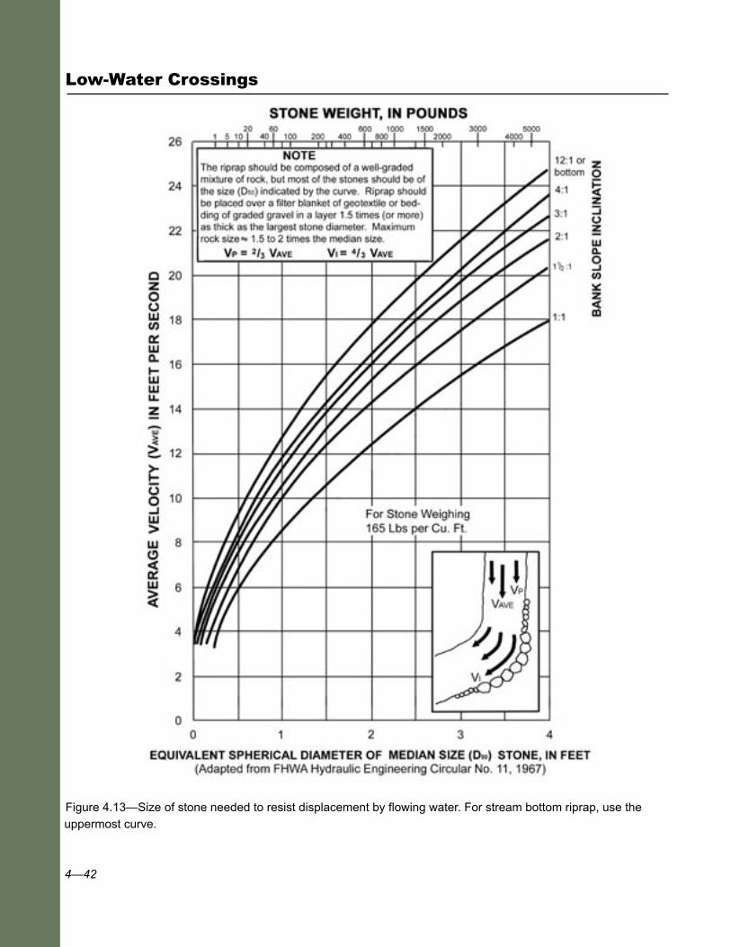
In figure 4.13 the median rock size (diameter or weight) is directly determined from average flow velocity and streambank (or road surface) slope. This method determines the size of riprap needed to protect the streambank and stay in place. Rock size is specified as the median, or D
50 size. Roughly half the riprap is larger than the size specified, and the
maximum size (D100
) rock is approximately 1.5 to 2 times the diameter of the median size. On straight stream segments, the velocity of water parallel to and near the bank (V
p) is assumed to be about 2/3, or 67 percent
the average velocity (Vave
) for the purpose of this analysis. On the outside of a bend, water flowing near the bank impinges on the bank, and the impinging velocity (V
i) is taken to be about 4/3, or 133 percent of the
average velocity (Vave
) (Racine et al.1996). In other words, riprap in an area with relatively fast flow, such as a bend in the channel, will have higher stresses and require larger rock than the size needed in a straight part of the channel.
Several other design and installation details are important when using riprap:
■ Use only well-graded riprap to provide a dense armoring layer. Although poorly-graded or uniform-size riprap can actually resist larger flows, it is not self-healing and can fail catastrophically. Riprap specifications are generally for graded rock, with a size range of large to small.
■ The riprap layer should be at least as thick as the maximum rock size, and preferably 1.5 times the maximum.
■ Use hard, durable, and angular rock, as specified in FP-03—”Standard Specifications for Construction of Roads and Bridges on Federal Highway Projects” (2003), or other agency specifications.
■ Place riprap on a filter layer of either gravel or geotextile. This placement allows water to drain from the soil while the filter
4—42
Low-Water Crossings
Figure 4.13—Size of stone needed to resist displacement by flowing water. For stream bottom riprap, use the uppermost curve.
4—43
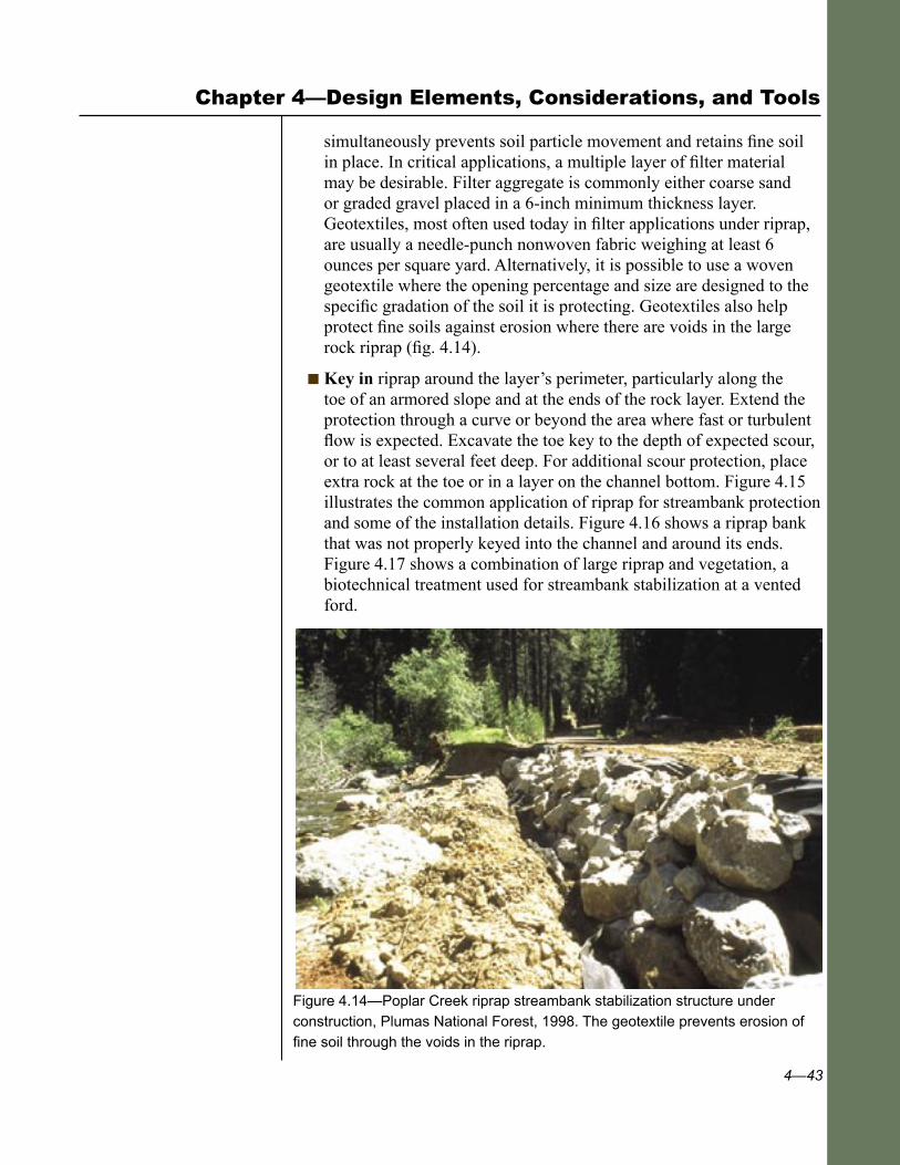
Chapter 4—Design Elements, Considerations, and Tools
simultaneously prevents soil particle movement and retains fine soil in place. In critical applications, a multiple layer of filter material may be desirable. Filter aggregate is commonly either coarse sand or graded gravel placed in a 6-inch minimum thickness layer. Geotextiles, most often used today in filter applications under riprap, are usually a needle-punch nonwoven fabric weighing at least 6 ounces per square yard. Alternatively, it is possible to use a woven geotextile where the opening percentage and size are designed to the specific gradation of the soil it is protecting. Geotextiles also help protect fine soils against erosion where there are voids in the large rock riprap (fig. 4.14).
■ Key in riprap around the layer’s perimeter, particularly along the toe of an armored slope and at the ends of the rock layer. Extend the protection through a curve or beyond the area where fast or turbulent flow is expected. Excavate the toe key to the depth of expected scour, or to at least several feet deep. For additional scour protection, place extra rock at the toe or in a layer on the channel bottom. Figure 4.15 illustrates the common application of riprap for streambank protection and some of the installation details. Figure 4.16 shows a riprap bank that was not properly keyed into the channel and around its ends. Figure 4.17 shows a combination of large riprap and vegetation, a biotechnical treatment used for streambank stabilization at a vented ford.
Figure 4.14—Poplar Creek riprap streambank stabilization structure under
construction, Plumas National Forest, 1998. The geotextile prevents erosion of fine soil through the voids in the riprap.
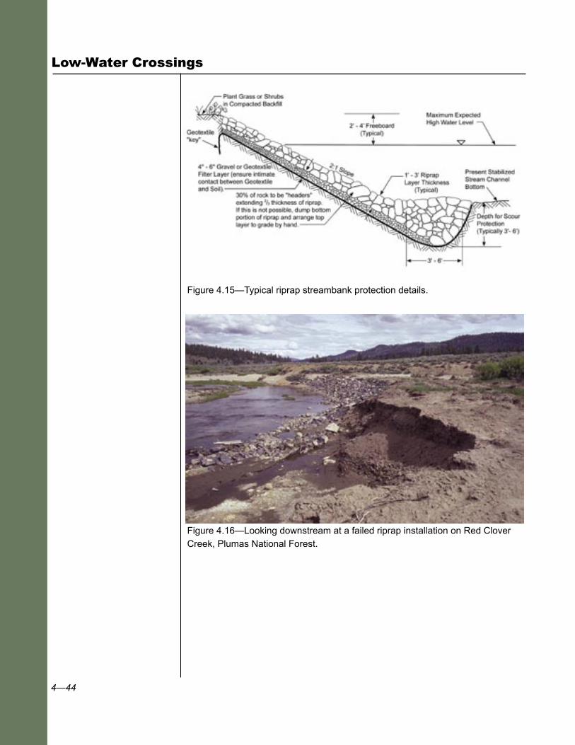
4—44
Low-Water Crossings
Figure 4.15—Typical riprap streambank protection details.
Figure 4.16—Looking downstream at a failed riprap installation on Red Clover Creek, Plumas National Forest.
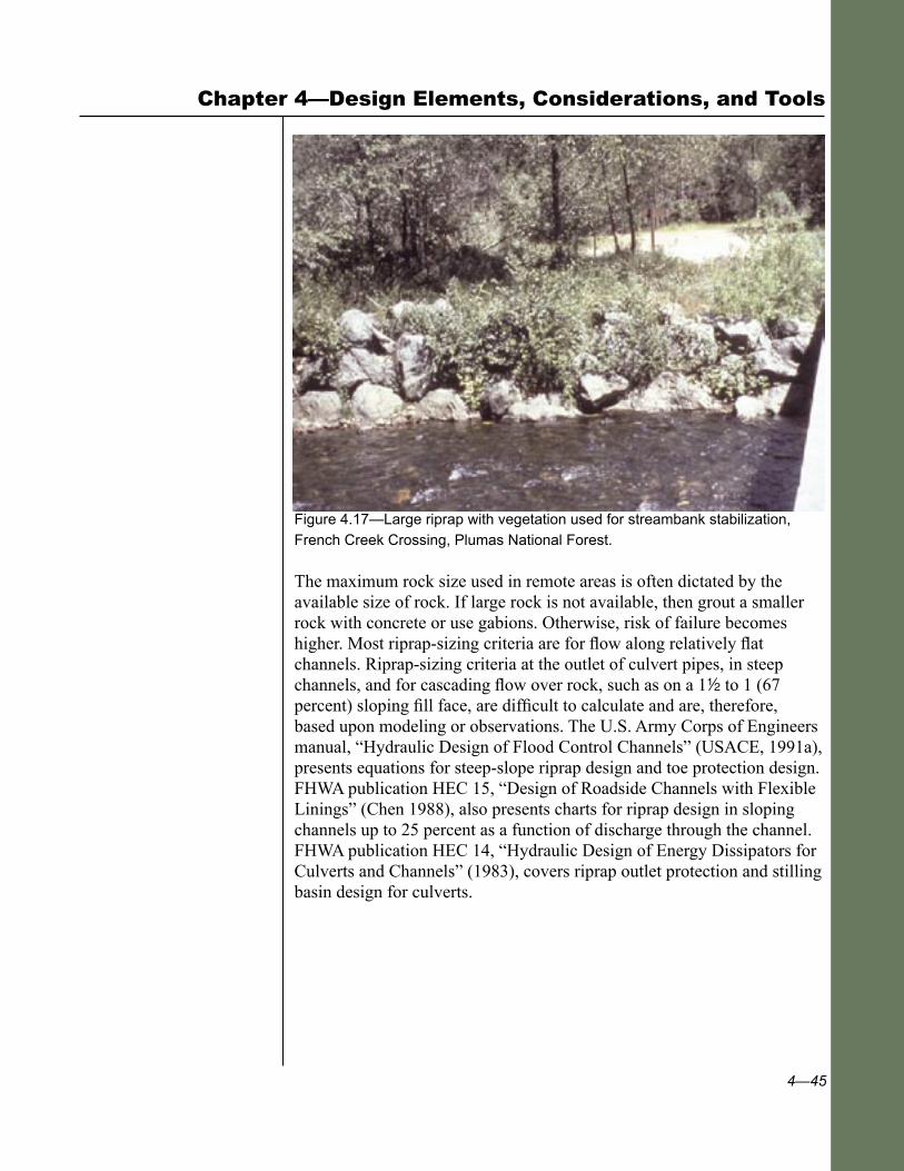
4—45
Chapter 4—Design Elements, Considerations, and Tools
Figure 4.17—Large riprap with vegetation used for streambank stabilization, French Creek Crossing, Plumas National Forest.
The maximum rock size used in remote areas is often dictated by the available size of rock. If large rock is not available, then grout a smaller rock with concrete or use gabions. Otherwise, risk of failure becomes higher. Most riprap-sizing criteria are for flow along relatively flat channels. Riprap-sizing criteria at the outlet of culvert pipes, in steep channels, and for cascading flow over rock, such as on a 12 to 1 (67 percent) sloping fill face, are difficult to calculate and are, therefore, based upon modeling or observations. The U.S. Army Corps of Engineers manual, “Hydraulic Design of Flood Control Channels” (USACE, 1991a), presents equations for steep-slope riprap design and toe protection design. FHWA publication HEC 15, “Design of Roadside Channels with Flexible Linings” (Chen 1988), also presents charts for riprap design in sloping channels up to 25 percent as a function of discharge through the channel. FHWA publication HEC 14, “Hydraulic Design of Energy Dissipators for Culverts and Channels” (1983), covers riprap outlet protection and stilling basin design for culverts.

4—46
Low-Water Crossings
4.7.3 Vegetation, Other Channel & Streambank Protection Measures
Vegetation is the most desirable method of streambank protection (as well as some channel protection where vegetation can grow) because of low cost, aesthetics, and compatibility with the natural environment. Vegetation alone, however, is typically suitable only for streambank protection with velocities in the range 1 to 5 feet per second. It is not adequate for protecting turbulent flow areas, areas of fast or impinging flows, midchannel piers, or areas generally underwater. Vegetative stabilization performance can be significantly improved by using it in conjunction with rootwads and boulders (figs. 4.18 and 4.19), biotechnical treatments, and reinforcing mats.
Figure 4.18—Rootwads and boulders used to stabilize a high streambank, Wolf Creek restoration project, Greenville, California, 1990.
To resist velocities up to 4 to 6 feet per second, use simple vegetation treatments with live stakes or brush mats. Well-installed biotechnical slope protection measures—using vegetation along with rootwads, tree trunks, or boulders—are suitable for velocities of at least 6 to 10 feet per second (Gray and Sotir 1996). For velocities greater than approximately 15 feet per second, hard armor systems are most commonly used (see fig. 4.10). In addition to NCHRP 544 (McCullah and Gray 2005), another excellent reference is the USDA NRCS (1996) “Engineering Field Handbook, Chapter 16, Streambank and Shoreline Protection,” which provides many examples of streambank protection measures with and without vegetation. Ideally, vegetation should be native, deep-rooted, and adapted to local site conditions. A variety of species, including willows, is commonly used.
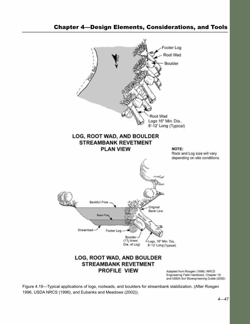
4—47
Chapter 4—Design Elements, Considerations, and Tools
Figure 4.19—Typical applications of logs, rootwads, and boulders for streambank stabilization. (After Rosgen 1996, USDA NRCS (1996), and Eubanks and Meadows (2002)).

4—48
Low-Water Crossings
In-channel scour protection treatments differ from treatments on the streambank. In-channel stabilization measures are principally rock, gabions, or concrete whereas streambank stabilization measures, especially above bankfull levels, are commonly vegetation, either alone or in conjunction with the more rigid measures.
As mentioned previously, if available rock is smaller than desired, either grout the small rock, put it in gabions, or build a solid concrete slab. Gabions are typically formed by filling the 1- to 4-cubic yard baskets with relatively small 4- to 8-inch cobbles. This effectively creates large rock baskets with small rocks. Generally, loose rock riprap is preferable because it is less expensive than gabions and can deform better in cases of local scour or undermining of the structure. Furthermore, gabion baskets can eventually fail by abrading or rusting out, requiring costly repairs or replacement (fig. 4.20). The useful life of gabions may only be 15 to 30 years—or less in aggressive environments—depending on location of the baskets, local corrosion conditions, type of corrosion protection, and the amount of abrasion from bed-load movement. When using gabions, protect them against scour by placing a filter layer (usually a geotextile) behind the baskets. Also, using them in conjunction with vegetation can improve their effectiveness.
The entire low-water-crossing structure can be used as a grade-control structure (case study 15) to protect the channel against degradation or downcutting. In such cases, include local scour prevention in the ford design. To determine the effect of the structure on the dynamics of the stream system, evaluate not only specific channel velocities and characteristics, but also the entire reach of the stream.
Structure placement or design can cause downstream deposition if the structure causes local scour immediately below the structure. When this happens, the sediment load increases beyond the amount normally carried by the stream, and the extra load is deposited farther down the channel. The result is a scour hole below the structure, followed by bar development farther downstream. Scour and deposition are examples of factors that must be considered when choosing the type of ford, its location, and its protection.
Again, structure protection must extend across the ford to at least the area of the structure’s wetted perimeter (the part sometimes under water), and preferably include 2 feet of freeboard to allow for flow uncertainties. Downstream of the structure, a scour cutoff or apron should be used. If waters will flow around the structure and over the banks, as in a broad flood plain environment, protect the banks both upstream and downstream of the structure with riprap or vegetation.
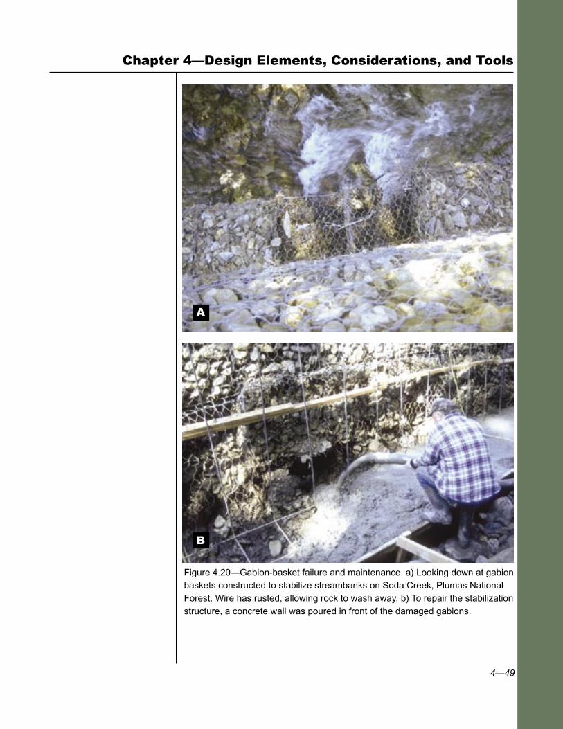
4—49
Chapter 4—Design Elements, Considerations, and Tools
Figure 4.20—Gabion-basket failure and maintenance. a) Looking down at gabion baskets constructed to stabilize streambanks on Soda Creek, Plumas National Forest. Wire has rusted, allowing rock to wash away. b) To repair the stabilization structure, a concrete wall was poured in front of the damaged gabions.
A
B
4—50
Low-Water Crossings
4.8 Structural Design of the Driving Surface
Most fords should be designed to pass a minimum legal 80,000-pound load, often designated as an HS 20-44 legal load (highway semi, 44-ton limit)1. If there is a load restriction on the road, post the weight limit at the ford. If overloads are anticipated, such as yarders or special construction equipment, the design (or temporary supports) must support those loads. Elevated structures such as box culverts, other vented fords, and low-water bridges should meet the same structural requirements as a normal structure designed for that site and span, as required in the FSH 7709.56b. For corrugated metal pipe structures, use a 1-foot minimum soil cover, unless the manufacturer recommends otherwise. Concrete pipe may require 18 inches of cover. When designing structures for lower load limits and lighter design vehicles, post the crossing (particularly if it is an elevated platform) for the allowable load limit.
For at-grade structures on granular soils, a legal load can usually be accommodated with a layer of aggregate 6- to 12-inches thick. The ford surface needs to resist the forces of low-water flow so we recommend a relatively coarse 12- to 2-inch minus, well-graded aggregate. To prevent displacement at high flows, place this surfacing aggregate over a layer of small to medium size riprap. Size the riprap based on figure 4.13, using the curve for a 12:1 or bottom slope. Geocells can be used to confine the aggregate, provide structural support, and prevent the aggregate from washing away. The geocells are typically covered with an additional 4 to 6 inches of aggregate to prevent damage to the cells. Compact any surfacing aggregate, and replace it periodically after high-flow events (case study 7). A stockpile of extra aggregate can be stored near the ford for periodic replacement.
Box structures and low-water bridges must have appropriate footings or foundations to support the traffic and dead load of the structure and to spread the load across the encountered soil or rock conditions. Reinforced concrete slabs, 6 to 8 inches thick, are commonly used on small box structures for the deck and abutment. In some cases, designers support the slab or vent on spread footings at least 2 feet wide and deeper than the expected depth of scour. Structures must have durable driving surfaces, curbs, and other features that can survive periods of inundation and have debris both hit them and go over them. Structural design should be based upon structural analysis and meet the current AASHTO bridge design
1The load reduction factor methodology (LRFD), which is expected to come into common use in the near future, may change the legal load. AASHTO’s 2007 LRFD “Design Bridge Specifications,” 4th edition, describes “Standard Specifications for Highway Bridges.”

4—51
Chapter 4—Design Elements, Considerations, and Tools
requirements for the anticipated loads. Many box-culvert designs are structurally adequate if built to the manufacturer’s recommendations. Preapproved designs from State departments of transportation are also used occasionally (case study 19).
Soft subgrade soils, such as silts, clay, and organic deposits, usually require overexcavation and backfilling with aggregate or select material for a 1- to 2-foot thickness. Very soft soils may require a subsurface investigation and site-specific design. Imported backfill material and/or the top foot of native material are often compacted to at least 90 percent of their AASHTO T-99 maximum density to provide adequate load-bearing support.
Vehicle use may compress organic meadow soils on the road approaches to a structure. As the soil compresses, the approaches lower in elevation, the channel widens at the crossing, and the original armoring on the roadway ceases to cover the entire wetted perimeter during high flow. Case study 7 demonstrates this problem. To remedy this type of situation, protect the banks by keying the structure in along the outer limits of the structure (well beyond bankfull), remove soft materials, replace them with aggregate, and reinforce the approach roadway to the structure.
For fords where vehicles drive through water most of the time, wave erosion can be an issue, both on the driving surface and on the streamside areas adjacent to the ford. Extend roadway surface armoring beyond the wetted perimeter to the likely height or distance of wave action (case study 7, fig. A38). Local streambanks may require additional vegetative or rock slope protection.
Where a road crosses an active flood plain the road surface should be very low or preferably at-grade with the flood plain to prevent obstructing or funneling flood flows. For structural support on fine or organic meadow soils, it may be necessary to overexcavate the roadway footprint and backfill it with select structural material, coarse rock, or aggregate. Place geotextile between the fine meadow soil and the roadway material to separate the materials and prevent contamination of the aggregate. Although an elevated porous rockfill embankment can be used (Zeedyk 1996), it will likely plug with time and dam the flood plain.

4—52
Low-Water Crossings
4.9 Safety
4.9.1 Traffic Safety
Traffic safety is a principal concern on low-water crossings. These crossings present particular safety issues, especially when driving through water and where there are dips in the roadway vertical alignment. For high-traffic use and high-standard, high-speed roads, low-water crossings are usually inappropriate, so this safety issue becomes irrelevant.
Because fords involve water periodically flowing over the road, they are inherently dangerous during those periods of inundation. As figure 3.1 shows, flows more than 1 to 2 feet deep have enough lateral force to push a vehicle off the ford. Fast water velocities are dangerous! Annually, numerous people are killed across the United States attempting to drive through fords or inundated sections of roads.
Despite warning signs and obviously unsafe road conditions suggesting the crossing not be used, fatalities still occur at these sites. Practicality and cost-effectiveness, however, dictate the use of low-water structures at many sites, particularly on low-volume roads. To provide for safety where fords are used, traffic engineers and resource managers must use prudent design and safety measures (such as traffic warning devices) along with aggressive driver education programs. When common sense indicates that a crossing may be especially hazardous—such as where the roadway platform is high above water, alignment is poor, speeds are relatively high, flows are swift and deep—the design should be carefully evaluated and a risk assessment made for the site.
Conventional guardrails and borders, typically 2 to 3 feet high, cannot be placed along most low-water-crossing structures because they will act as trash racks during overtopping, and are likely to be damaged during high flows. We recommend low curbs, borders, or delineators for defining the roadway, identifying the edge of the structure, and keeping traffic on the structure, particularly where the structure is raised. For safety and to minimize flow and debris obstruction, use 6- by 10-inch-high timber curbs, preferably raised to 12 inches with blocks for scuppers, or use 15-inch-high concrete curbs (FSH 7709.56b). See case studies 14, 18, 20, and 21 for examples. Use object markers to define each corner of the structure, but place them out of the active flow channel to avoid snagging debris.
The need for safety measures increases with the height of the structure, particularly on vented fords and low-water bridges where the roadway
4—53
Chapter 4—Design Elements, Considerations, and Tools
platform is elevated more than a couple of feet. When conventional bridge railings are not used, USDA Forest Service policy for structures states the site will be evaluated for safety based upon traffic speed, traffic volume, alignment, structure dimensions, other local hazards, and curb design. This analysis (design warrant) is then documented and kept in the project design file. If the ford cannot be made safe, then a conventional bridge with safety railings or another type of structure should be built.
Ideally, low-water crossings should be located where the road is straight and sight distance is good. Adequate warning signs are critical for identifying the approaching ford and warning drivers that the crossing may be flooded and have periodic traffic delays. Marker posts indicating the depth of flow are desirable, particularly with unvented, at-grade fords. FHWA uses a safe but conservative design criterion for vented fords that limits water depth over the structure to 6 inches during the high-design flow. This limit greatly reduces the likelihood of a vehicle being swept away if it enters the water. This criterion, however, may require large vents and is impractical or costly to implement on many unvented fords on rural or forest roads. Therefore, warning devices are the more practical solution in most applications.
Use traffic warning signs along the road, notifying traffic that it is approaching a low-water crossing and that there is the possibility of flooding. Suggested warning signs should include “FLOOD AREA AHEAD,” “IMPASSABLE DURING HIGH WATER,” and “DO NOT ENTER WHEN FLOODED.” A suggested arrangement of these signs, as recommended by FHWA (Gu 2003), appears in figure 4.21. Similar signing is recommended in the “USDA Forest Service Sign Manual,” FS EM 7100-15.
Where practical, use depth markers to indicate the depth of flow over the structure (fig 4.22). Depth markers may be impractical or require periodic maintenance in channels carrying a lot of debris. Alternatively, a system of colored posts could be used where flow level green suggests safe passage, flow level yellow suggests marginally safe conditions, and flow level in the red zone indicates an unsafe condition.
For additional traffic safety, we recommend extra width through the structure (an additional several feet), particularly with at-grade fords. On raised fords with embankments, a 4:1 (horizontal:vertical) or flatter slope is desirable. Minimize safety problems by avoiding steep road grades and curves into a crossing.
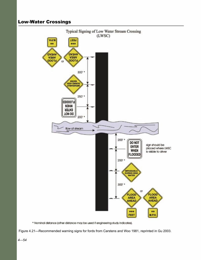
4—54
Low-Water Crossings
Figure 4.21—Recommended warning signs for fords from Carstens and Woo 1981, reprinted in Gu 2003.
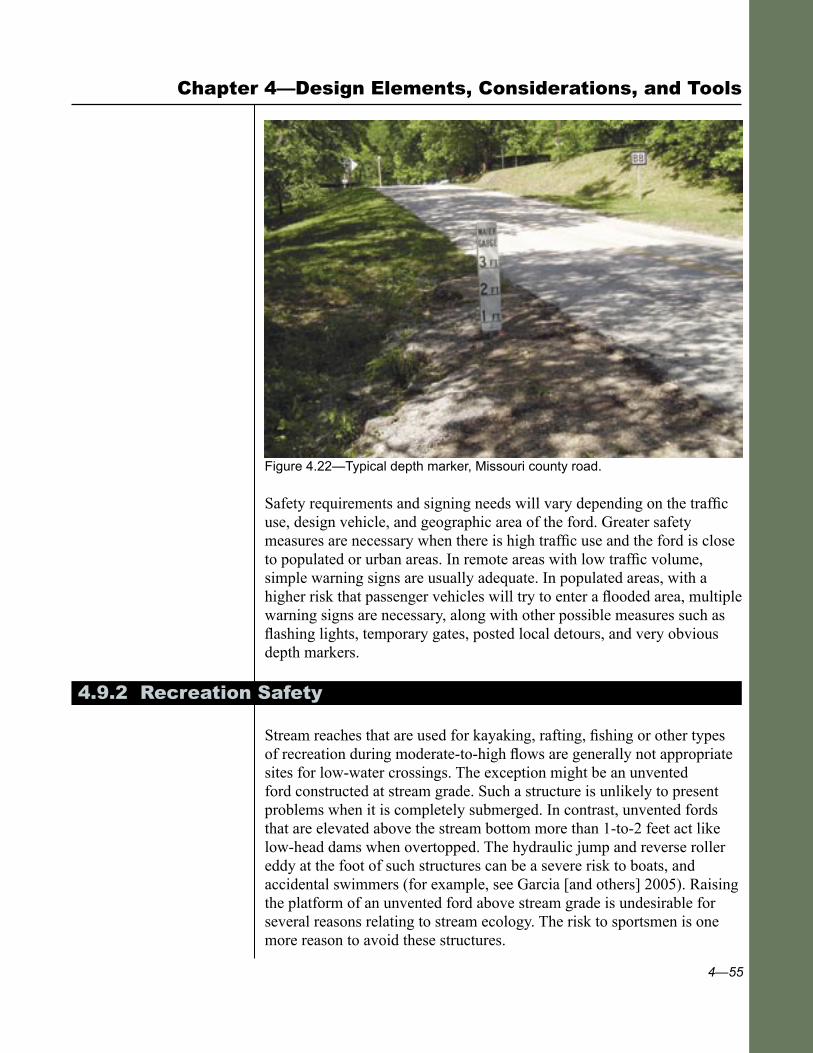
4—55
Chapter 4—Design Elements, Considerations, and Tools
Figure 4.22—Typical depth marker, Missouri county road.
Safety requirements and signing needs will vary depending on the traffic use, design vehicle, and geographic area of the ford. Greater safety measures are necessary when there is high traffic use and the ford is close to populated or urban areas. In remote areas with low traffic volume, simple warning signs are usually adequate. In populated areas, with a higher risk that passenger vehicles will try to enter a flooded area, multiple warning signs are necessary, along with other possible measures such as flashing lights, temporary gates, posted local detours, and very obvious depth markers.
4.9.2 Recreation Safety
Stream reaches that are used for kayaking, rafting, fishing or other types of recreation during moderate-to-high flows are generally not appropriate sites for low-water crossings. The exception might be an unvented ford constructed at stream grade. Such a structure is unlikely to present problems when it is completely submerged. In contrast, unvented fords that are elevated above the stream bottom more than 1-to-2 feet act like low-head dams when overtopped. The hydraulic jump and reverse roller eddy at the foot of such structures can be a severe risk to boats, and accidental swimmers (for example, see Garcia [and others] 2005). Raising the platform of an unvented ford above stream grade is undesirable for several reasons relating to stream ecology. The risk to sportsmen is one more reason to avoid these structures.
4—56
Low-Water Crossings
Low-VAR fords present the same similarities to low-head dams, along with the additional risk to accidental swimmers that their bodies can be pulled into and pinned against a culvert opening, potentially sealing it and creating suction. If a crossing with this kind of hazard must be left in place, the most effective way to prevent someone from being sucked into the pipe would be installing a raised grating or trash rack over the inlet. Other possible safety retrofits are to bevel the inlet to increase the surface area of the opening. For projecting inlets, scalloping the edges or perforating the pipe will help to avoid creation of a tight seal.
Even high-VAR fords and low-water bridges are undesirable on streams with frequent recreational use during high flows, particularly if the crossing is on a bend and cannot be seen from upstream. Adding trash racks or large-mesh screens or gratings can protect people, but will add considerably to maintenance requirements. Consider placing warning signs along the river upstream of the structure, and providing places to land, portage around the structure, and reenter the river.
4.10 Materials Selection
Materials selection is important in several aspects of low-water crossing design and construction. These aspects include the driving surface, the structural design of vented fords or low-water bridges, and the selection of streambank and scour protection measures. Choice of materials for constructing a low-water crossing depends on many factors, including the following:
■ Type of structure.
■ Availability and cost of materials.
■ Proximity of materials to the site.
■ Desired useful life of the structure.
■ Anticipated stream channel velocity.
Many fords use local rock for both the roadway surface and bank protection. Rock is simple to use, usually inexpensive, natural, and aesthetic. Although local rock and riprap may be available and inexpensive, they will be suitable only if hard and durable, and if the material’s size is large enough to resist movement by the forces of water.

4—57
Local stream channel material, both rock and finer material, is ideal for refilling embedded box culverts to achieve stream simulation or create as natural a channel condition as possible through the structure.
If large enough rock is not available for scour protection or streambank stabilization, use alternative materials, such as gabions, a mix of boulders and logs, grouted riprap, masonry, or massive concrete. Use gabions when a structure is needed and cobble-size materials (4 to 8 inches) are plentiful. For advantages and disadvantages of gabions, as well as other alternatives, see section 4.7. In relatively low-velocity areas, vegetative material alone may be suitable for bank protection.
Structural concrete is the most commonly used material for vented fords, complicated structures, and even simple improved fords placed in a dynamic stream environment. Structural concrete is strong and durable. If properly mixed and placed, and not undermined, it can have a design life of 100 years. For vented fords and low-water bridges with slabs or spans supporting a traffic load, its structural strength often makes it the best choice. It is resistant to abrasion, does not corrode (if the steel reinforcement is properly placed in a good mix), and requires minimal maintenance. Alternatives to concrete use are masonry walls and abutments. For improved aesthetics, the concrete can be colored, textured, shaped, faced with rock, or hidden behind vegetation.
The roadway driving surface can be constructed of a wide variety of materials including local rock, aggregate confined in geocells (case study 7), gabions, concrete planks (case studies 5 and 10), asphalt, cable concrete blocks (case study 6), or a massive concrete slab (case studies 8 and 9).
Materials such as gabions, precast Jersey barriers (K-rail), or low concrete walls can be used to support or build up the downstream edge of a ford. Choice will generally depend on cost. Jersey barriers are often used for temporary structures in storm damage repair or after forest fires because they are relatively durable, portable, and reusable (fig. 5.12).
Chapter 4—Design Elements, Considerations, and Tools

4—58
Low-Water Crossings
4.11 Best Management Practices for Erosion Control and Water Quality Protection
4.11.1 Maintaining Water Quality
Road-stream crossings are critical areas of concern for water quality due to the potential for large road fills, road surface drainage entering the stream network, and limited opportunities for mitigation. (Also see appendix D.) Stream crossings are the point where the road and water courses most directly connect. Using outsloped roads or insloped roads with frequent cross-drains will minimize the concentration of water on a road surface and minimize sediment delivery to crossings. Adding a rolling dip or cross-drain exiting into a stable buffer area just before the crossing will further minimize the connectivity. Locate the rolling dip or cross-drain as close to the crossing as possible to minimize the amount of connected road surface, but far enough away to have an adequate filter strip to settle out sediments draining from the rolling dip or cross-drain. Finally, armor the roadway surface nearest the crossing to the first cross- drain or break in slope. If the roadway slopes smoothly to the crossing, armor at least the last 150 feet.
Although fords with unsurfaced approaches provide the most obvious potential sediment source, with the road surface as the conduit, other structures may have ditches that are neither armored nor vegetated. Depending on slope and soil type, those ditches may not only transport road sediment to the stream but also undergo active incision, thus adding their own sediment. Even well-maintained graveled road surfaces will deliver some sediment (Reid and Dunne 1984) to nearby streams. Well-drained and armored crossings will minimize this sediment delivery. Also, crossings with a broad surface area or multiple crossings on a drainage can increase water temperature to some extent. The amount and significance of any temperature increase should be evaluated on a site-specific basis.
To best protect water quality, create a general erosion-control plan and a project plan incorporating specific structure design elements aimed at preventing bed and bank erosion and local scour, and implementing BMP’s. See section 4.7 for structure design elements that deal with changes in velocity and the effects on the in-stream environment. BMP’s exist for a wide variety of management activities, including those both in and near the channel.
Material collected on the dry road surface and in ditches washes into the stream when it rains. Excluding vehicle use during rainy periods reduces but does not prevent road sediment transport to the stream (Bilby et al
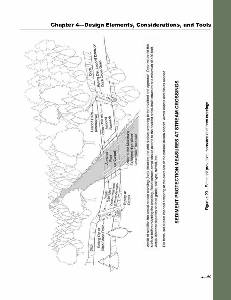
4—59
Fig
ure
4.23
—S
edim
ent p
rote
ctio
n m
easu
res
at s
trea
m c
ross
ings
.
Chapter 4—Design Elements, Considerations, and Tools
4—60
Low-Water Crossings
1989). Low-water crossing sediment control measures are shown in figure 4.23. They include the following:
■ Armoring the roadway approaches and driving surface through the crossing.
■ Using vented fords to avoid driving through the water most of the time.
■ Using armored ditches approaching the crossing.
■ Diverting the ditch water with cross-drains and leadoff ditches before it reaches the crossing channel.
■ Diverting surface water with rolling dips before it enters the crossing.
■ Armoring the entire structure and channel area affected by the structure.
■ Maintaining the structure and roadway adequately.
Construction dewatering of the site is an excellent way to protect water quality and minimize sediment production during construction. Working in water and preserving water quality is very difficult, particularly if water is flowing. Working in a dry, isolated, and dewatered site is much simpler for both construction and water-quality protection. Plan construction projects during the dry season or periods of low flow if possible. Dewatering ford sites commonly involves working during periods of minimum flow, building an upstream cutoff wall or diversion dam, and running the flow through a culvert (often 12- to 24-inch corrugated metal or plastic pipe) around the construction site. At some sites, dewatering systems need to accommodate fish passage.
At sites with seasonal or ephemeral flow, conduct work when the site is dry, but be prepared for potential storms. Use sump pumps to keep the site dry during low flows or if excavation extends below the local groundwater table. Discharge pumped water into a holding tank or sediment catchment basin before returning it into the flowing stream. Sediment-laden water can sometimes be treated by spreading it over a vegetated area away from the flowing stream, where the water can infiltrate trapping sediment in the soil. Water containing leachates from cement is toxic to most aquatic organisms so this contaminated water should be kept out of the stream and disposed of properly.
4—61
4.11.2 Erosion Control
Plan and schedule all construction activities to prevent erosion and sedimentation, which could cause water quality degradation and possible adverse effects on aquatic species. Erosion control measures for fords include the following:
■ Netting, vegetation, and ground cover for any disturbed areas such as work areas, storage areas, materials sources, and exposed earthwork, both during and after construction.
■ Controlling water in ditches flowing into the crossing and across disturbed or denuded earthwork areas.
■ Trapping sediment in catchment basins, behind silt fences, or in-channel with sediment mattresses.
■ Minimizing sedimentation from construction in-channel.
■ Protecting exposed overflow areas.
Other elements of erosion control include scheduling the work to reduce the risk of erosion, stopping work during rainfall events, keeping clean and dirty water separated, minimizing site disturbance, installing erosion control measures before site disturbance occurs, and periodically maintaining the erosion control measures. It is important to integrate erosion control into as many design considerations as possible, including the selection of materials sources, revegetation of all working areas, and drainage control through the construction site.
Erosion control is most relevant during construction and for the first year after construction. During construction, keep the work out of flowing water, or use sediment catchment areas. Limit disturbed or denuded areas to areas small enough to be protected during rainstorm events, or limit construction to the dry season.
Develop a project-wide erosion control plan to ensure a variety of feasible erosion control treatments are considered and include the cost of those measures in the project budget. A wide variety of erosion control measures are usually workable, including physical methods (e.g., ditches and berms, mats, riprap), vegetative methods (e.g., grasses, brush, trees) and biotechnical measures (e.g., brush layering, use of live stakes, vegetation, and rock wattles). Promote the long-term success of the measures by providing for maintenance, monitoring, and follow-up work. Erosion control measures are well-documented in numerous references such as Gray and Sotir (1996) and ABAG (1995).
Chapter 4—Design Elements, Considerations, and Tools

4—62
Low-Water Crossings
4.11.3 Best Management Practices
To satisfy water-quality concerns, incorporate standard erosion and sediment control practices (BMPs) into all projects as needed, particularly during construction. You must adapt all BMPs to site-specific conditions, as discussed in “Water Quality Management for Forest System Lands in California—Best Management Practices” (USDA Forest Service 2000) and in the draft national standards, “Best Management Practices—Nonpoint Source Management,” USDA, Forest Service, May 2005. Review project design to ensure appropriate BMPs are incorporated into the design and construction requirements. Monitoring the implementation and effectiveness of BMPs is also necessary for resource and structure protection and for identifying additional maintenance needs. The following is a partial list of typical BMPs that apply to the construction of low-water crossings:
Erosion Control Plan Create this plan before starting the project. Include the specific practices to be implemented for controlling erosion and preventing management-caused sediment from reaching the drainage. Ensure compliance by frequent inspections.
Stream Crossing Location Like all stream crossings, locate low-water crossings perpendicular to
the channel on a straight stretch, whenever possible. Although difficult when retrofitting old crossings or working with certain landforms, this positioning will reduce the effects of streamflow energy on the structure itself as well as impacts resulting from the redirection of flow against channel banks.
Timing of Construction Activities When feasible, schedule activities in and near the channel during the dry
season, or for a time period when precipitation and runoff are unlikely. Stop construction during times when soils are too wet for equipment to operate without damaging the soil resource and increasing the potential for water quality degradation.
Timely Erosion Control Measures on Incomplete Stream Crossing Projects Whenever a project must remain only partially completed for a time, use
the following erosion prevention measures:
4—63
■ Remove temporary culverts, diversion dams, or other structures that could obstruct or narrow streamflow, increase scour or bank erosion potential (by increasing the velocity and flow through a narrow opening), or increase erosive power against channel banks.
■ Install necessary erosion control structures such as temporary culverts, side drains, flumes, cross-drains, diversion ditches, energy dissipators, dips, sediment basins, berms, debris racks, or silt fences.
Construction of Stable Embankments Construct approaches and road surfaces with adequate strength to
support the treadway, shoulders, subgrade, and traffic loads. When fills are required, stabilize embankments with retaining walls, confinement systems, plantings, or a combination, as needed. Adequately compact all road surfaces.
Control of Road Drainage A great number of methods can help reduce the effects of increased runoff
and sediment transport caused by low-water crossings and road ditches. These methods include dips that shunt water off the road near the crown of the approach, culverts that carry water from a road ditch and disperse it on the other side away from the channel, paved approaches, and armored ditches. In areas without sufficient distance for safely dispersing road and ditch water, slow the flow by using sediment basins, check dams, contour trenching in the discharge area, or other similar methods.
Servicing and Refueling Construction Equipment Keep service and refueling areas well away from wet areas, surface
water, and drainages. Minimize soil contamination potential by using berms around these sites, and using impermeable liners or other techniques to contain spills (see forest Spill Prevention, Containment, and Countermeasures plan).
Controlling In-ChannelExcavation Heavy equipment should cross or work in and near streams only under
specific protection requirements. Excavation in these areas should follow all of the following minimum water quality protection requirements:
■ Do not excavate outside of caissons, cribs, cofferdams, or sheet pilings, unless previously authorized.
■ Do not disturb natural streambeds adjacent to the structure.
■ Keep disturbance of banks to a minimum, and stabilize any banks that are disturbed.
Chapter 4—Design Elements, Considerations, and Tools

4—64
Low-Water Crossings
Diversion of Flows Around Construction Sites Divert streamflow around construction sites and return it to the natural
streamcourse as soon as possible after construction, or before the wet season. Stabilize all disturbed areas before the wet season or as needed.
Specifying Riprap Composition Size and install riprap to resist erosive water velocities. Do not include
any material that might add to the sediment load, such as weakly structured rock, organic material, or soil. To prevent undermining, it may be necessary to use filter blankets or other methods.
Control of Construction and Maintenance Activities Adjacent to Stream Areas Properly functioning streamside areas act as filters for sediment, provide
shade and habitat, stabilize banks, and help slow velocities and limit the erosive potential of floodwaters. Establish the width of these areas and keep fill and similar materials out of them, except for specifically designated areas. Protecting these areas may necessitate stabilizing adjacent fillslopes to prevent sediment accumulations within the stream side areas.
Structure Maintenance Structures and approaches may suffer deterioration from either large
runoff events or normal use. Provide the basic maintenance to protect the structure and prevent damage to resources. This high level of maintenance often requires an annual inspection to ensure structure and channel compatibility, function, and stability.
Water Quality Monitoring Although implementing BMPs generally gives a high degree of water
quality protection, some projects require verification of BMP effectiveness through a testing program. Water quality parameters and test methods should be specified by an established water quality monitoring plan.