chapter 47 - guidelines for preparing utility plans€¦ · 2 guidelines for preparing utility...
TRANSCRIPT
MONTANA RIGHT-OF-WAY
DESIGN MANUAL
Chapter Forty-Seven
GUIDELINES FOR PREPARING
UTILITY PLANS

Jan. 2016 GUIDELINES FOR PREPARING UTILITY PLANS i
Chapter Forty-Seven
GUIDELINES FOR PREPARING UTILITY PLANS
Table of Contents
Section Page
47-1 UTILITY PLANS OVERVIEW ............................................................................... 2
47-2 UTILITY PLANS PREPARATION ......................................................................... 3
47-2.1 Title Sheet ............................................................................................... 3
47-2.2 Table Contents, Notes Sheet ................................................................... 6
47-2.3 Linear and Level Data Sheet ................................................................... 7
47-2.4 Control Diagram and Abstract Sheet ....................................................... 8
47-2.5 Ownership Sheet ................................................................................... 10
47-2.6 Typical Section Sheet ............................................................................ 12
47-2.7 Summary Sheet ..................................................................................... 14
47-2.8 Detail Sheet ........................................................................................... 16
47-2.8.1 Detail Sheet 1 – No Maps ..................................................... 16
47-2.8.2 Detail Sheet 2 – With Maps .................................................. 17
47-2.9 Plan and Profile Sheets ......................................................................... 19
47-2.10 Identifying Utility Conflicts ...................................................................... 25
47-2.10.1 Lateral conflicts ..................................................................... 25
47-2.10.2 Spot conflicts ........................................................................ 25
47-2.10.3 Other Conflicts ...................................................................... 26
47-2.10.4 Utility Crossings .................................................................... 26
47-2.11 Example Plan Sheets ............................................................................ 26
2 GUIDELINES FOR PREPARING UTILITY PLANS Jan. 2016
Chapter Forty-Seven
GUIDELINES FOR PREPARING UTILITY PLANS
47-1 UTILITY PLANS OVERVIEW
Utility plans are created when existing utilities lie within the construction limits of a
project. The primary purpose of the plans is to highlight the utilities and their
relationship to the other project data. The plans are used by Utility Engineering
Specialists as they coordinate with the utility companies to determine the extent of
relocation necessary within a given project. The plans are also used to create exhibits
that become part of the final utility agreements.
47-1.1 Typical plan set
1. Title Sheet
2. Table of Contents, Notes, Linear and Level Data Sheet(s)
3. Control Diagram and Abstract Table Sheet(s)
4. Ownership Sheet(s)
5. Typical Section Sheet(s)
6. Summary Sheet(s) – Included in the utility plan set when utility items requiring adjustment such as valves, manholes or fire hydrants are noted on plan and profile sheets.
7. Detail Sheet(s)
8. Plan and Profile Sheet(s)
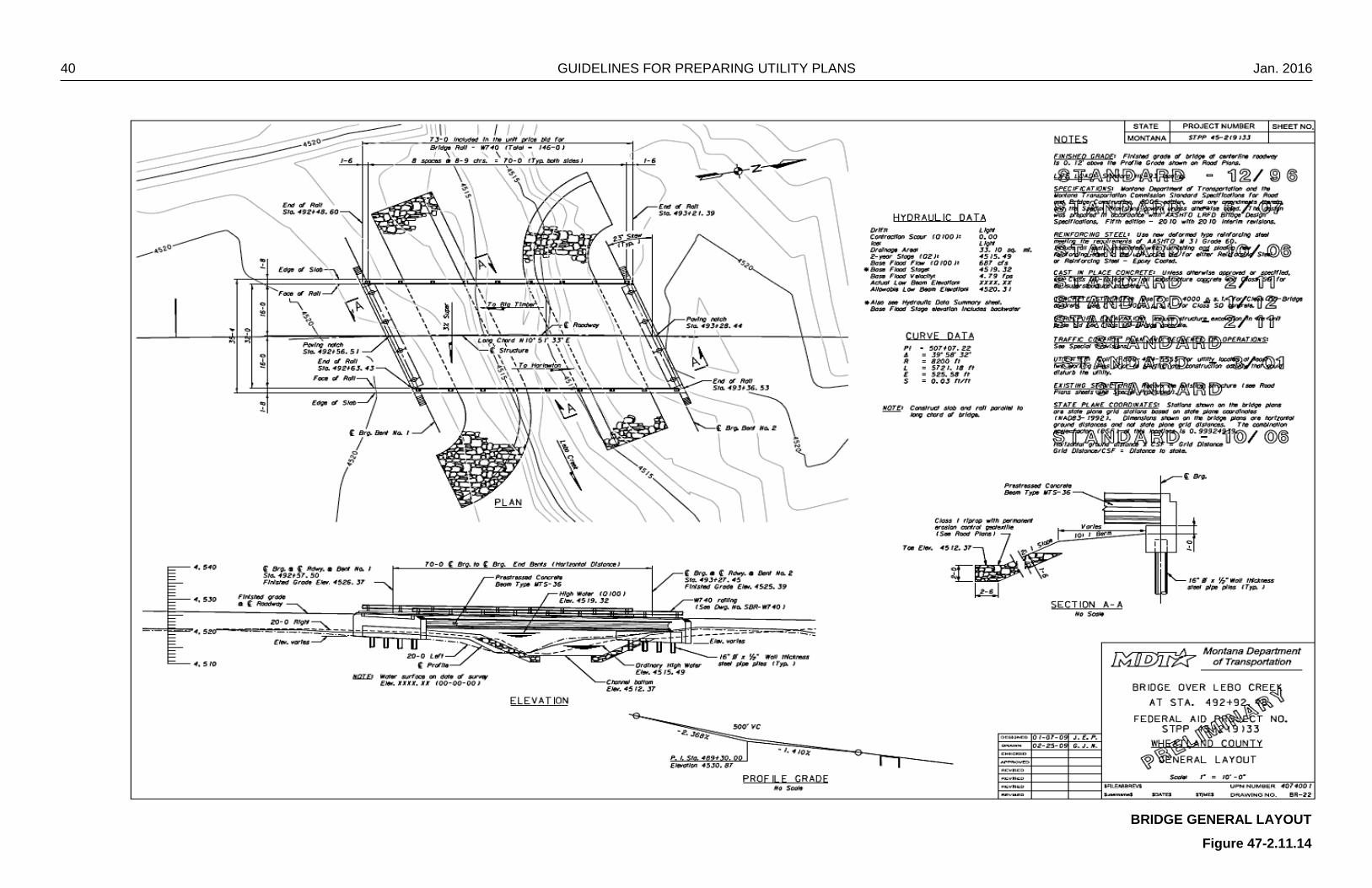
9. Bridge General Layout Sheet(s) – Included in the utility plan set when bridge work is included in the project.
Sheet requirements, level lists and color lists used as examples in this guide are partial
and are not typical of every project.

Jan. 2016 GUIDELINES FOR PREPARING UTILITY PLANS 3
47-2 UTILITY PLANS PREPARATION
47-2.1 Title Sheet
The title sheet should show the project location on the state map and in more detail on
the county map. It should include the project beginning and ending stations; bridge
stations, if any, and clearly identify the route number and county. A plan legend will also
be included showing standard symbols and symbology shown on the utility plans.
Related and associated projects along with the FHWA/MDT approval and R/W map
revised block are also included. Design data, federal R/W project number, project name,
county and project length are shown on the utility title sheet.
All reference to design files assumes proper DMS naming conventions have been
followed. In this and all other procedures 1234000 represents the 7-digit project control
number.
EXAMPLE: 1234000RDPLN001.DGN
UPN Number Work Area Work Area Series Number File Type
1234000 RD PLN 001 DGN
Creating the utility title sheet:
1. Download the title sheet from the RD workgroup in DMS usually named 1234000RDTTL001. Copy this file to the c:\dgn\ref directory for referencing.
2. Download the title sheet from the RO workgroup in DMS usually named
1234000ROTTL001. Copy this file to the c:\dgn\ref directory for referencing.
3. Open RD Title sheet, save it as UT title sheet (ex. 1234000UTTTL001.DGN)
Place a fence around all elements in the file, delete the active elements, then compress the file.
4. Attach UTILITYV8_0.tbl (color table), UTILITYV8_OE.cel (cell library) from
ftp://ftp.mdt.mt.gov/caddstd/WORKGROUP/UTSTD/ . 5. In ‘Active file’ ‘View Attributes’, turn on Level Overrides. 6. In ‘Reference’ ‘Settings’ ‘Level Display’, choose MTSTD:PLANE.REF, set filter to
UTTTL.

4 GUIDELINES FOR PREPARING UTILITY PLANS Jan. 2016
7. In ‘Reference’ ‘Settings’ ‘Level Manager’, choose MTSTD:PLANE.REF, set all style and weight attributes to off, all color attributes to 0 except as follows:
Name Number Color
. S_BOT_UT_TITLE Wetland Hatch 10603 40
. S_BOT_UT_TITLE Legend Text 10604 0
. S_BOT_UT_TITLE Legend Symbols 10605 0
. S_BOT_UT_TITLE Legend Power 10606 3
. S_BOT_UT_TITLE Legend Telephone 10607 6
. S_BOT_UT_TITLE Legend Gas 10608 56
. S_BOT_UT_TITLE Legend TV 10609 5
. S_BOT_UT_TITLE Legend Water 10610 1
. S_BOT_UT_TITLE Legend San Sewer 10611 2
8. ‘Clip Mask’ the text in the design data box in the upper right corner from
MTSTD:PLANE.REF. 9. Turn off levels designating “Scales” and “Title North Arrow” in MTSTD:PLANE
REF. 10. Attach RD Title Sheet as a reference with RDTTL-1 as the logical name.
11. Copy the project location arrow into the active file. 12. Clip boundary around the county map and related project information. Move as
necessary to display properly.
13. Attach RD Title Sheet as a reference with RDTTL-2 as the logical name. 14. Clip boundary around RDTTL-2 to display only the design data in the upper right
corner.
15. Attach RO Title Sheet as a reference with ROTTL-1. 16. Clip boundary around ROTTL-1 to show data for associated projects, map
revised and FHWA/MDT approval boxes.
17. Attach cell “STDSHTDF” from cell library. It is inserted at XY=50000, 50000. 18. Fill in the data for the project information. This cell contains the county name,
project name, project UPN, project number, scale factor and sheet number data fields for the bottom of the pages.
19. Attach cell “TTLSHTDF” from cell library. It is inserted at XY=50000, 50000.
Jan. 2016 GUIDELINES FOR PREPARING UTILITY PLANS 5
20. Fill in the data for the title sheet. This cell contains the county name, project
name, project number and project length data fields for the main title area under MONTANA DEPARTMENT OF TRANSPORTATION.
21. In ‘Reference’ ‘Settings’ ‘Level Manager’, set the color to 0, line weight and symbology override to off in RDTTL-1, RDTTL-2, ROTTL-1 and the active file.
6 GUIDELINES FOR PREPARING UTILITY PLANS Jan. 2016
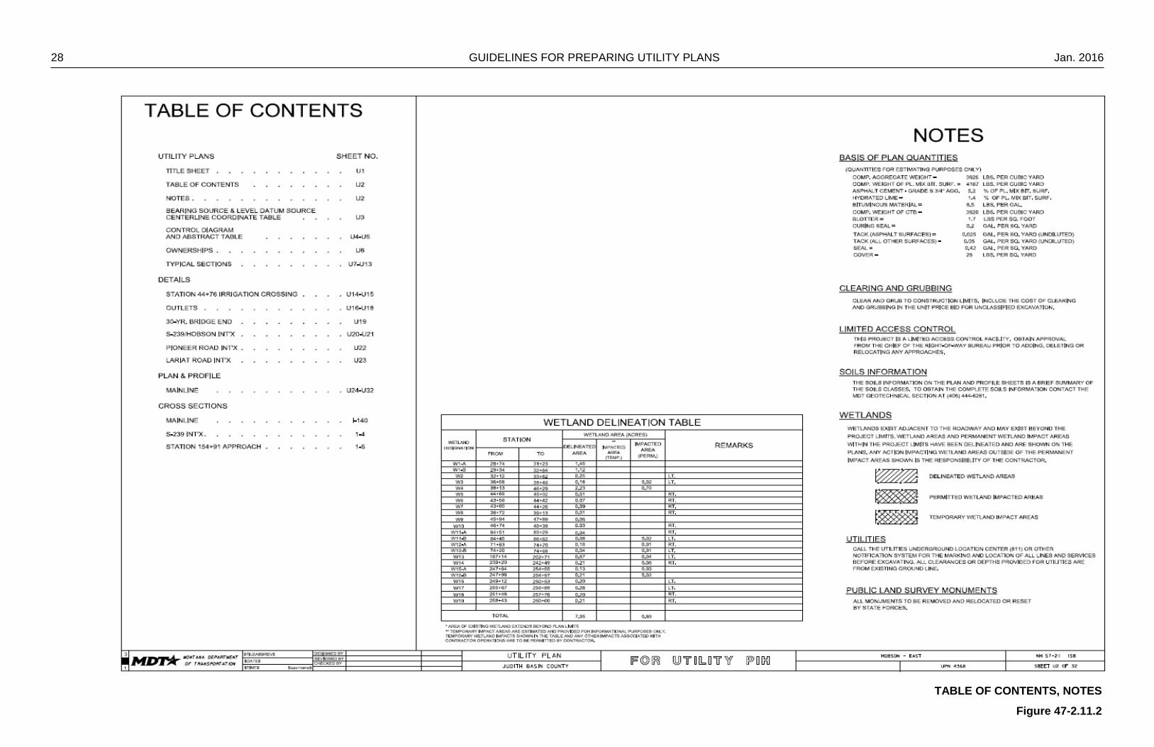
47-2.2 Table Contents, Notes Sheet
The table of contents is unique to the utility plans and lists all sheets contained in the
utility plans package. All sheets in the utility plans begin with a capital “U” in the page
number sequencing, with the exception of the cross sections, they are a direct copy
from the road design plans and numbered accordingly. Other items that may be
included on this sheet are notes, skew diagram, clear zone table and linear & level data.
The following procedure assumes the table of contents is to be included as page 2 in
the title sheet file “1234UTTTL001”. All references to design files assume proper DMS
naming convention has been followed.
Use the following procedure for creating the utility table of contents sheet:
1. Open design file 1234UTTTL001 and window area to view sheet 2. 2. Attach RD Title Sheet as a reference with RDTTL-3 as the logical name.
Clip boundary around RDTTL-3 to display only the NOTES section.
3. Attach cell “TOCMID” from cell library. It is inserted at XY=50000, 50000. Move as needed to fit page. Drop status and fill in the information when known.
4. In ‘Reference’ ‘Settings’ ‘Level Manager’, set the color to 0, line weight and symbology override to off in RDTTL-3 and the active file.
Jan. 2016 GUIDELINES FOR PREPARING UTILITY PLANS 7
47-2.3 Linear and Level Data Sheet
Use the following procedure for creating the utility linear and level data sheet:
1. Open design file 1234UTTTL001 and window area to view sheet 3. 2. Attach RD Title Sheet as a reference with RDTTL-4 as the logical name.
3. Clip boundary around RDTTL-4 to display only the Linear and Level Data
section.
4. Move as needed to fit page. 5. In ‘Reference’ ‘Settings’ ‘Level Manager’, set the color to 0, line weight and
symbology override to off in RDTTL-4 and the active file.
8 GUIDELINES FOR PREPARING UTILITY PLANS Jan. 2016
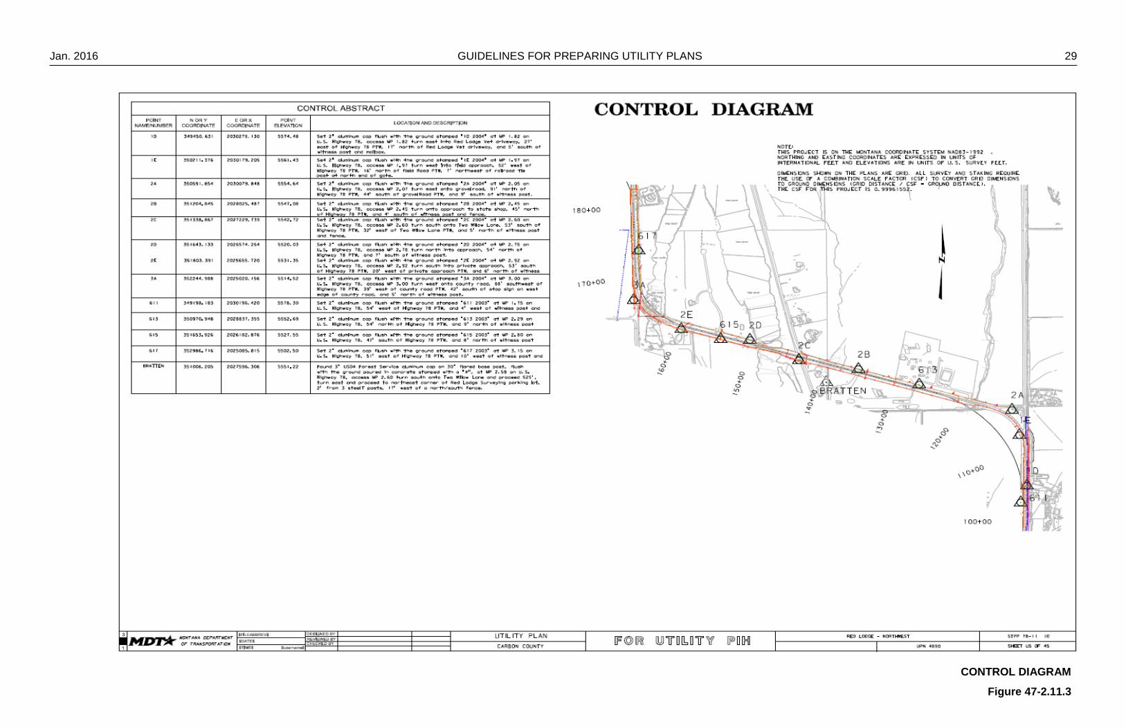
47-2.4 Control Diagram and Abstract Sheet
The control diagram is used to establish a permanent, recoverable horizontal and
vertical control system for highway design and construction. All topography and design
data, including utilities, hydrology, right-of-way, bridge and miscellaneous data, is tied to
the control diagram. The control abstract gives the coordinates and elevation of each
control point along with a brief description of how to find or reach the control point. The
control diagram and abstract are made available to utility companies for use in
engineering utility relocation work and are included in the utility plans package.
All reference to design files assumes proper DMS naming conventions have been
followed. The following procedure assumes a new utility design file is to be made for
the control diagram and abstract, and the control diagram abstract will fit on one sheet.
Modifications to this procedure, the procedure itself, or portions of the procedure may
need to be repeated, if more than one sheet is needed for the complete control diagram
and abstract.
Use the following procedure for creating the utility control diagram and abstract sheet:
1. Download the traverse file from the RD workgroup in DMS, usually named 1234000RDTRV001. Copy this file to the c:\dgn\ref directory for referencing.
2. Open RD Traverse sheet, save it as UT traverse sheet (ex.
1234000UTTRV001.DGN) Place a fence around all elements in the file, delete the active elements,
then compress the file.
3. Attach UTILITYV8_0.TBL (color table) and UTILITYV8_0E.CEL (cell library) from ftp://ftp.mdt.mt.gov/caddstd/WORKGROUP/UTSTD/ .
4. In ‘Active file’ ‘View Attributes’, turn on Level Overrides. 5. In ‘Reference’ ‘Settings’ ‘Level Display’, choose MTSTD:PLANE.REF, set filter to
UTDET. Turn of level “Detail Title Block” for bottom, mid and top.
6. In ‘Reference’ ‘Settings’ ‘Level Manager’, choose MTSTD:PLANE.REF, set all style and weight attributes off, color attributes to 0 (white).
7. Attach RD Traverse Sheet as a reference with RDTRV-1 as the logical name.
Clip boundary around the reference to display the Control Diagram & Abstract sheet.

Jan. 2016 GUIDELINES FOR PREPARING UTILITY PLANS 9
8. Attach all survey, utility map and right of way files (PH, DI, UTSUE, UTMAP, ROMAP etc.) if not already attached.
Scale, Rotate, and Move the files to fit the displayed control points of the traverse.
Turn on levels from survey map files to show general topography such as fences, buildings, streams, ptw, mailboxes, etc.
Turn on levels from utility map files to show the utilities. Turn on levels from right of way map files to show section lines. In ‘Reference’ ‘Settings’ ‘Level Manager’, for the survey files set the color
to 80, line weight and symbology override to off, except utility features. In ‘Reference’ ‘Settings’ ‘Level Manager’, for the utility files set the line
width and symbology override to off and the color symbology as follows:
Water levels – color 1 Sanitary sewer levels – color 2 Power levels – color 3 TV levels – color 5 Communication levels – color 6 Gas levels – color 56 Drainage levels – color 0
In ‘Reference’ ‘Settings’ ‘Level Manager’, for the right of way files set the
color to 0, line weight and symbology override to off.
9. Attach cell “STDSHTDF” from cell library. It is inserted at XY=50000, 50000. 10. Fill in the data for the project information. This cell contains the county name,
project name, project UPN, project number, scale factor and sheet number data fields for the bottom of the pages.
11. In ‘Reference’ ‘Settings’ ‘Level Manager’, choose active file and set all style and
weight attributes off, color attributes to 0 (white). 12. In ‘Reference’ ‘Settings’ ‘Update Sequence’ and change update sequence as
follows:

10 GUIDELINES FOR PREPARING UTILITY PLANS Jan. 2016
47-2.5 Ownership Sheet
The ownership sheet gives the names and addresses of the adjacent property owners
along the highway construction project. The ownership sheet also states the right-of-
way, easement and construction permit areas needed from each property owner for the
proposed construction project. The property owners are shown by parcel numbers and
cross-referenced to the utility plan sheets. Also shown with the ownership sheet are the
FHWA/DOT approval date and the date of the last revision to the right-of-way map.
All reference to design files assumes proper DMS naming conventions have been
followed. The following procedure assumes a new utility design file is to be made for
the ownership sheet, and the ownerships will fit on one sheet. This procedure may
need to be repeated, if more than one sheet is needed for the complete ownerships of
the project.
Use the following procedure for creating the utility ownership sheet:
1. Download the ownership file from the RO workgroup in DMS that contains the ownership data, usually named 1234000ROOWN001. Copy this file to the c:\dgn\ref directory for referencing.
2. Open RO Owner sheet, save it as UT owner sheet (ex.
1234000UTOWN001.DGN) Place a fence around all elements in the file, delete the active elements,
then compress the file.
3. Attach UTILITYV8_0.TBL (color table) and UTILITYV8_0E.CEL (cell library) from ftp://ftp.mdt.mt.gov/caddstd/WORKGROUP/UTSTD/ .
4. In ‘Active file’ ‘View Attributes’, turn on Level Overrides. 5. In ‘Reference’ ‘Settings’ ‘Level Display’, choose MTSTD:PLANE.REF, set filter to
UTOWN. In ‘Reference’ ‘Settings’ ‘Level Manager’, choose MTSTD:PLANE.REF,
set all style and weight attributes off, color attributes to 0 except as follows:
Levels 10647, 10632, and 10636 to color 40 (gray).
6. Attach RO Ownership Sheet as a reference with ROOWN-1 as the logical name. Clip boundary around ROOWN-1 to display the ownership information, no
page numbers. In ‘Reference’ ‘Settings’ ‘Level Manager’, for the set the color to 0, line
weight and symbology override to off.
Jan. 2016 GUIDELINES FOR PREPARING UTILITY PLANS 11
7. Attach RO Ownership Sheet as a reference with ROOWN-2 as the logical name. Clip boundary around ROOWN-2 to show data for associated projects,
map revised and FHWA/MDT approval dates. In ‘Reference’ ‘Settings’ ‘Level Manager’, for the set the color to 0, line
weight and symbology override to off.
8. Attach cell “STDSHTDF” from cell library. It is inserted at XY=50000, 50000. Fill in the data for the project information. This cell contains the county
name, project name, project UPN, project number, scale factor and sheet number data fields for the bottom of the pages.
9. Attach cell “UTOWNDF1” from cell library. It is inserted at XY=50000, 50000.
Fill in the data for the utility plans page numbers when known. The parcel numbers are shown on the plan and profile sheets. This cell contains data fields under the SHEET NO. heading of the ownership data for sheet 1. If creating more than one ownership sheet, the number of the cell will increment with the sheet (UTOWNDF2 for sheet 2, etc.).
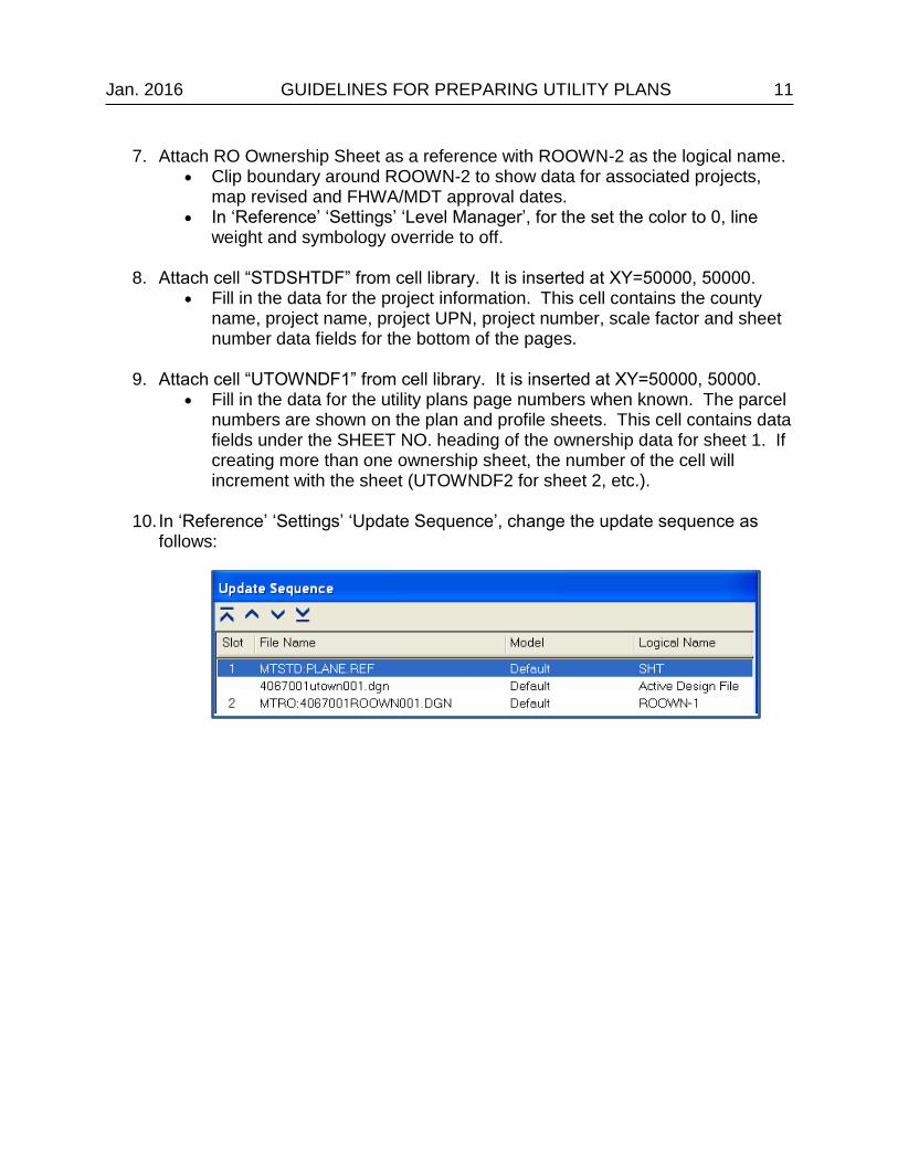
10. In ‘Reference’ ‘Settings’ ‘Update Sequence’, change the update sequence as
follows:

12 GUIDELINES FOR PREPARING UTILITY PLANS Jan. 2016
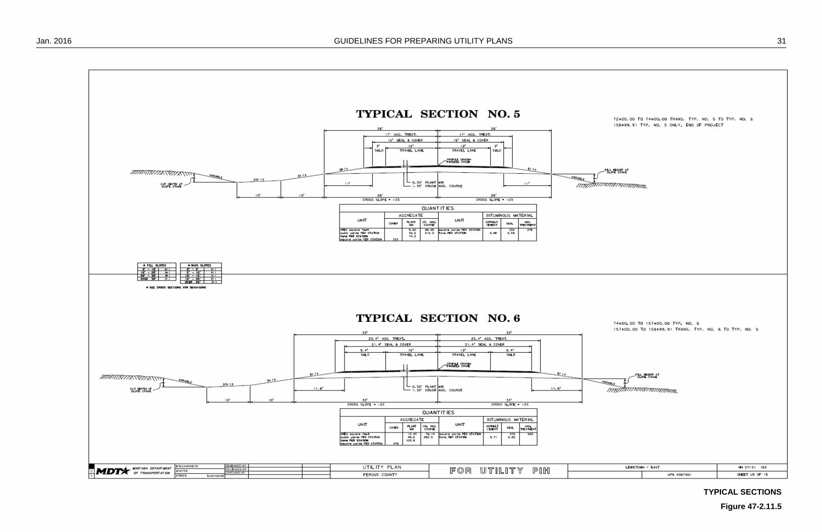
47-2.6 Typical Section Sheet
One or more typical sections are required for each set of plans. Typical sections are
used to illustrate the cross section for a roadway section, the basis for surfacing
quantities, roadway widths for tangent and super-elevated sections, and cut and fill
slope rates. Typical sections also show roadside ditches, curbed and uncurbed
sections, median widths, sidewalks, driving lanes, shoulder widths, turn lanes and other
roadway surface features.
Note that all reference to design files assumes proper DMS naming conventions have
been followed. The following procedure assumes a new utility design file is to be made
for the typical sections and that the typical sections will fit on one sheet.
Use the following procedure for creating the utility typical sections:
1. Download the typical section file from the RD workgroup in DMS that contains the typical section data, usually named 1234000RDTYP001. Copy this file to the c:\dgn\ref directory for referencing.
2. Open RD Typical sheet, save it as UT typical sheet (ex.
1234000UTTYP001.DGN) Place a fence around all elements in the file, delete the active elements,
then compress the file.
3. Attach UTILITYV8_0.TBL (color table) and UTILITYV8_0E.CEL (cell library) from ftp://ftp.mdt.mt.gov/caddstd/WORKGROUP/UTSTD/ .
4. In ‘Active file’ ‘View Attributes’, turn on Level Overrides. 5. In ‘Reference’ ‘Settings’ ‘Level Display’, choose MTSTD:PLANE.REF, set filter to
UTTYP. 6. In ‘Reference’ ‘Settings’ ‘Level Manager’, choose MTSTD:PLANE.REF, set all
style and weight attributes off, color attributes to 0 (white). 7. In “References’, rename reference that has logical name of (e) to
MTRD:1234000RDTYP### where new name matches name of original typical section file before saving as UT.
Change the property of the reference attachment to “No Nesting”.
8. Attach RD Typical Section Sheet as a reference with RDTYP-1 as the logical name.
Clip boundary around RDTYP-1 to display the typical section information for sheet 1.
Jan. 2016 GUIDELINES FOR PREPARING UTILITY PLANS 13
In ‘Reference’ ‘Settings’ ‘Level Manager’, set the colors to 0, line weight and symbology override to off.
9. Repeat steps for all typical section sheets. 10. Attach cell “STDSHTDF” from cell library. It is inserted at XY=50000, 50000.
Fill in the data for the project information. This cell contains the county name, project name, project UPN, project number, scale factor and sheet number data fields for the bottom of the pages.

14 GUIDELINES FOR PREPARING UTILITY PLANS Jan. 2016
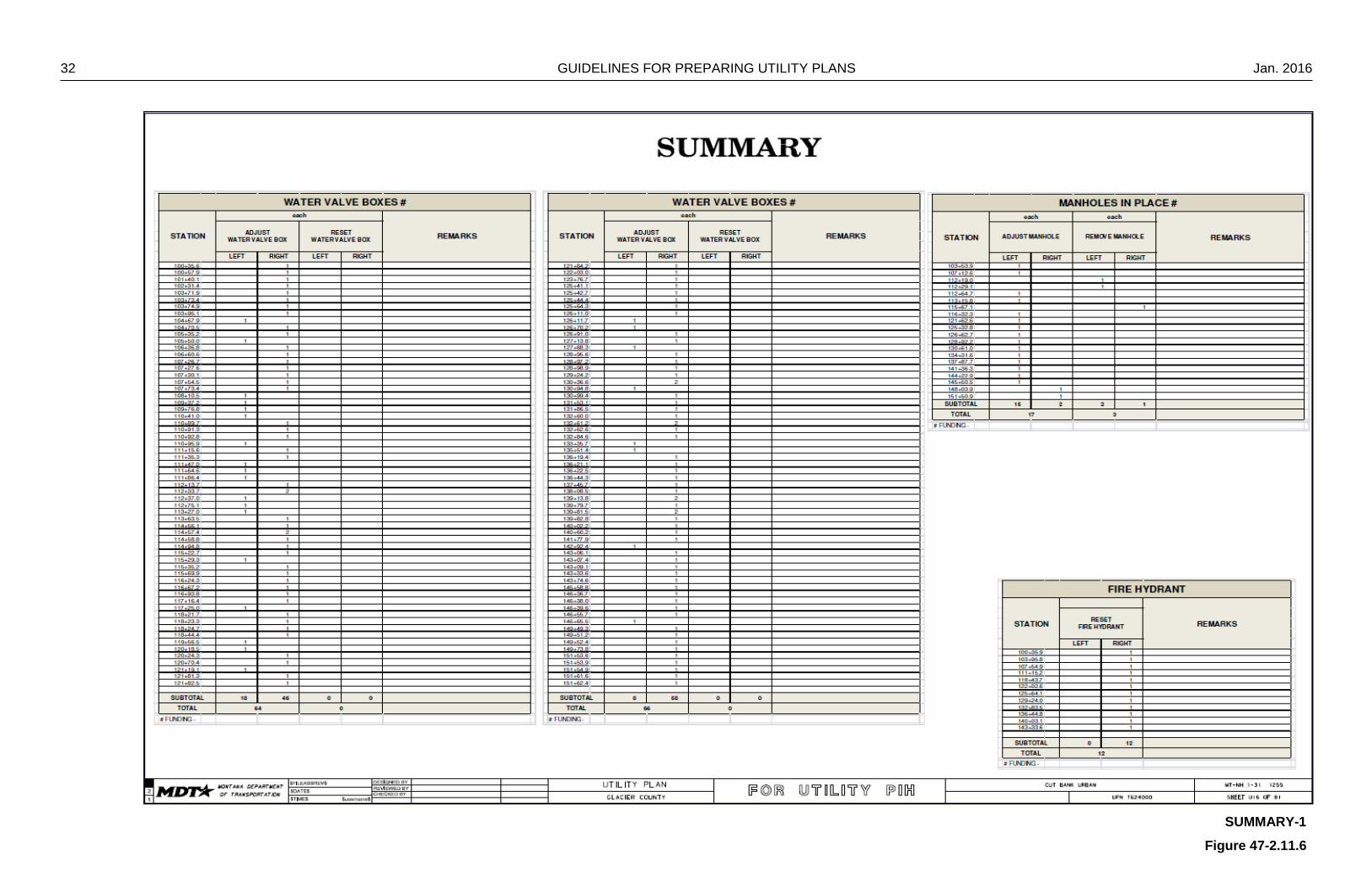
47-2.7 Summary Sheet
When plan and profile sheets contain manholes, valves and/or fire hydrants requiring
adjustment or relocation, a summary sheet shall be included in the utility plan set. The
summary sheet contains tables showing the station, left or right offset from centerline,
and the ownership of each item type. It also contains the funding level of the
adjustments which varies from project to project. The utility agent determines the
funding source and percentage of the state’s participation from procedures established
by law.
Note that all reference to design files assumes proper DMS naming conventions have
been followed. The following procedure assumes a new utility design file is to be made
for the summaries and that they will fit on one sheet.
1. Download the summary sheet file from the RD workgroup in DMS that contains the summary sheet data, usually named 1234000RDSUM001. Copy this file to the c:\dgn\ref directory for referencing.
2. Open RD Summary sheet, save it as UT typical sheet (ex.
1234000UTSUM001.DGN) Place a fence around all elements in the file, delete the active elements,
then compress the file.
3. Attach UTILITYV8_0.TBL (color table) and UTILITYV8_0E.CEL (cell library) from ftp://ftp.mdt.mt.gov/caddstd/WORKGROUP/UTSTD/ .
4. In ‘Active file’ ‘View Attributes’, turn on Level Overrides. 5. In ‘Reference’ ‘Settings’ ‘Level Display’, choose MTSTD:PLANE.REF, set filter to
UTDET. Turn off the level “Detail Title Block” for bottom, mid and top.
6. In ‘Reference’ ‘Settings’ ‘Level Manager’, choose MTSTD:PLANE.REF, set all style and weight attributes off, color attributes to 0 (white).
7. Attach RD Summary Sheet as a reference with RDSUM-1 as the logical name.
Clip boundary around the reference to display the summary items as needed. Only show those tables that reflect items requiring adjustment as noted above.
In ‘Reference’ ‘Settings’ ‘Level Manager’, set the colors to 0, line weight and symbology override to off.

Jan. 2016 GUIDELINES FOR PREPARING UTILITY PLANS 15
8. Attach cell “STDSHTDF” from cell library. It is inserted at XY=50000, 50000.
Fill in the data for the project information. This cell contains the county name, project name, project UPN, project number, scale factor and sheet number data fields for the bottom of the pages.
16 GUIDELINES FOR PREPARING UTILITY PLANS Jan. 2016
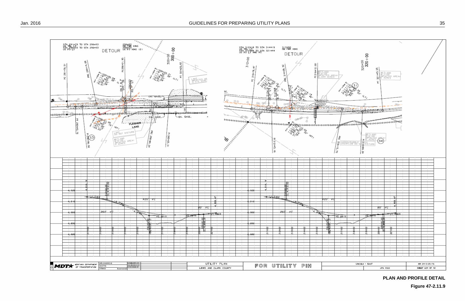
47-2.8 Detail Sheet
Detail sheets are used for those items that require more specific information than can
be adequately described on the plan and profile sheets. Details in the utility plans may
include: detours, rumble strips, drainage details, signing, electrical or geometric details.
Mass diagrams are not included with the utility plans. Each project will have its own
unique set of details and inclusion of each detail is determined on a project-by-project
basis.
All reference to design files assumes proper DMS naming conventions have been
followed. The following procedure assumes a new utility design file is to be made for
the details, and the details will fit in one design file.
47-2.8.1 Detail Sheet 1 – No Maps
1. Download the file from the RD workgroup in DMS that contains the details, usually named 1234000RDDET001. Copy this file to the directory c:\dgn\ref for referencing.
2. Open RD detail sheet, save it as UT detail sheet (ex. 1234000UTDET001.DGN)
Place a fence around all elements in the file, delete the active elements, and then compress the file.
3. Attach UTILITYV8_0.TBL (color table) and UTILITYV8_0E.CEL (cell library) from
ftp://ftp.mdt.mt.gov/caddstd/WORKGROUP/UTSTD/ . 4. In ‘Active file’ ‘View Attributes’, turn on Level Overrides.
5. In ‘Reference’ ‘Settings’ ‘Level Display’, choose MTSTD:PLANE.REF, set filter to
UTDET.
6. In ‘Reference’ ‘Settings’ ‘Level Manager’, choose MTSTD:PLANE.REF, set all style and weight attributes off, color attributes to 0 (white).
7. Attach RD Detail Sheet as a reference with RDDET-1 as the logical name.
Clip boundary around RDDET-1 to display the detail information. In ‘Reference’ ‘Settings’ ‘Level Manager’, for the set the color to 0, line
weight and symbology override to off.
8. Attach cell “STDSHTDF” from cell library. It is inserted at XY=50000, 50000. Fill in the data for the project information. This cell contains the county
name, project name, project UPN, project number, scale factor and sheet number data fields for the bottom of the pages.
Jan. 2016 GUIDELINES FOR PREPARING UTILITY PLANS 17
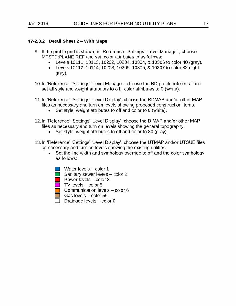
47-2.8.2 Detail Sheet 2 – With Maps
9. If the profile grid is shown, in ‘Reference’ ‘Settings’ ‘Level Manager’, choose MTSTD:PLANE.REF and set color attributes to as follows:
Levels 10111, 10113, 10202, 10204, 10304, & 10306 to color 40 (gray). Levels 10112, 10114, 10203, 10205, 10305, & 10307 to color 32 (light
gray).
10. In ‘Reference’ ‘Settings’ ‘Level Manager’, choose the RD profile reference and set all style and weight attributes to off, color attributes to 0 (white).
11. In ‘Reference’ ‘Settings’ ‘Level Display’, choose the RDMAP and/or other MAP
files as necessary and turn on levels showing proposed construction items. Set style, weight attributes to off and color to 0 (white).
12. In ‘Reference’ ‘Settings’ ‘Level Display’, choose the DIMAP and/or other MAP files as necessary and turn on levels showing the general topography.
Set style, weight attributes to off and color to 80 (gray).
13. In ‘Reference’ ‘Settings’ ‘Level Display’, choose the UTMAP and/or UTSUE files as necessary and turn on levels showing the existing utilities.
Set the line width and symbology override to off and the color symbology as follows:
Water levels – color 1 Sanitary sewer levels – color 2 Power levels – color 3 TV levels – color 5 Communication levels – color 6 Gas levels – color 56 Drainage levels – color 0

18 GUIDELINES FOR PREPARING UTILITY PLANS Jan. 2016
14. In ‘Reference’ ‘Settings’ ‘Update Sequence’, change the update sequence similar to the following:
Jan. 2016 GUIDELINES FOR PREPARING UTILITY PLANS 19
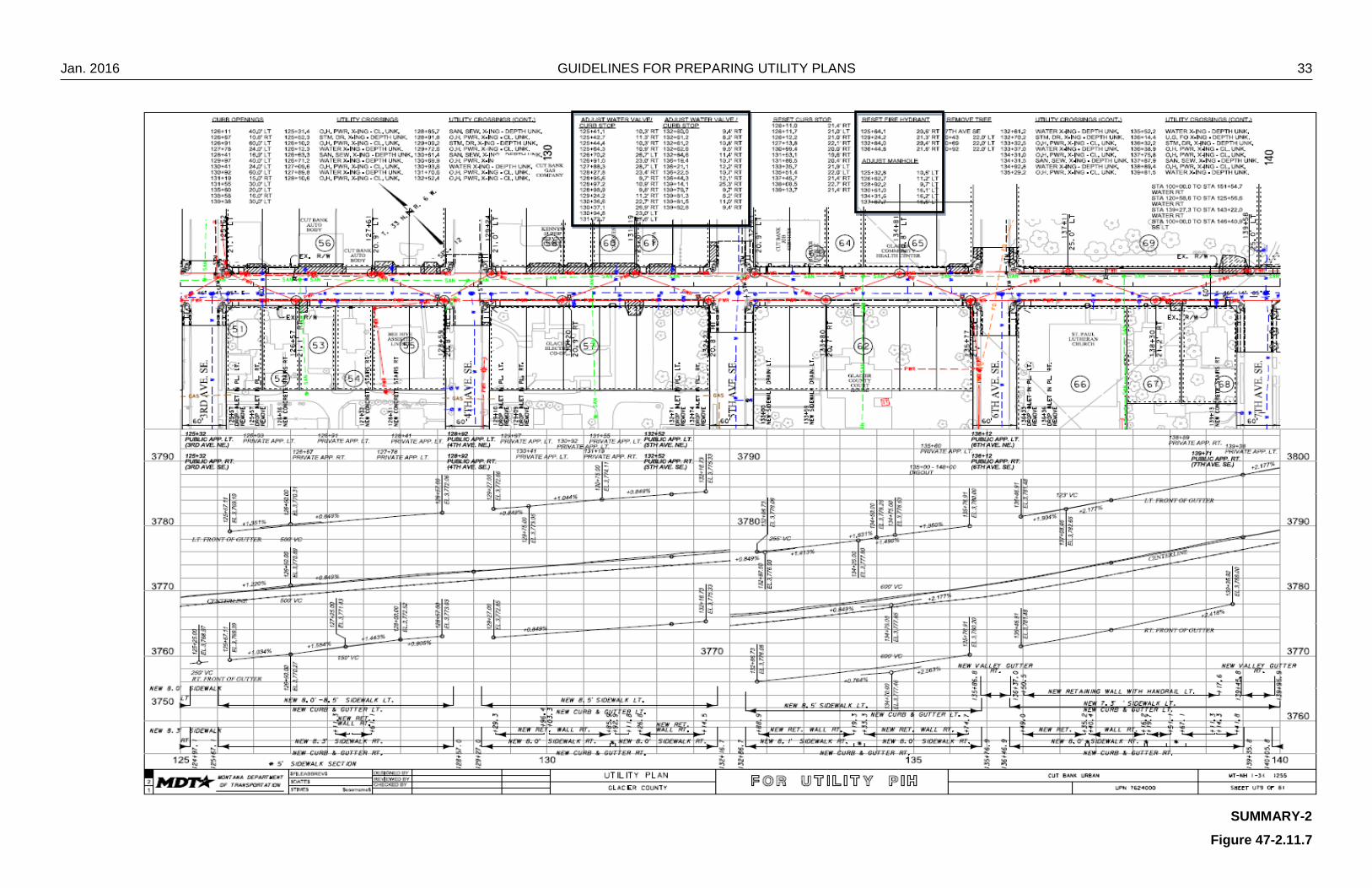
47-2.9 Plan and Profile Sheets
The intent of the utility plan and profile sheets is to clearly distinguish the relationship
between construction, right-of-way and other design features with the utilities located
along or adjacent to the proposed highway construction project. The utility plan and
profile sheet resembles the Department’s standard plan and profile sheet, but with the
profile portion of the sheet reduced, expanding the plan portion of the sheet.
As a general rule in the utility plan and profile sheets, existing topography items (e.g.,
buildings, trees, ex. R/W) are shown with gray lines, new items (e.g., const. limits,
pipes, new R/W) are shown with black lines and all utilities are shown with the proper
color coded lines.
Note that all reference to design files assumes proper DMS naming conventions have
been followed. The following procedure assumes that a SUE survey was performed
locating all above and belowground utilities and that all mapping and survey files follow
CADD standards with regards to levels. The procedure also assumes a new utility
design file is to be made for the plan sheets, and the plan sheets will fit in one design
file. The procedure will need to be repeated or modified if more than one plan\profile
sheet design file is needed.
Use the following procedure for creating utility plan\profile sheets:
1. Download the file from the RD workgroup in DMS that contains the plan and profile, usually named 1234000RDPLP001. Copy this file to the directory c:\dgn\ref for referencing.
2. Open RD detail sheet, save it as UT detail sheet (ex. 1234000UTPLP001.DGN)
Place a fence around all elements in the file, delete the active elements, and then compress the file.
3. Attach UTILITYV8_0.TBL (color table) and UTILITYV8_0E.CEL (cell library) from
ftp://ftp.mdt.mt.gov/caddstd/WORKGROUP/UTSTD/ .
4. In ‘Active file’ ‘View Attributes’, turn on Level Overrides.
5. In ‘Reference’ ‘Settings’ ‘Level Display’, choose MTSTD:PLANE.REF, set filter to UTPLP.

20 GUIDELINES FOR PREPARING UTILITY PLANS Jan. 2016
6. In ‘Reference’ ‘Settings’ ‘Level Manager’, choose MTSTD:PLANE.REF, set all style and weight attributes off, color attributes to 0 (white) except as follows:
Levels 10111, 10113, 10202, 10204, 10304, & 10306 to color 40 (gray). Levels 10112, 10114, 10203, 10205, 10305, & 10307 to color 32 (light
gray).
7. Attach RD Plan Sheet as a reference with RDPLP-1 as the logical name. Clip boundary around RDPLP-1 to display the plan and profile information.
8. Repeat as necessary for remaining plan and profile sheets in the file (RDPLP-2, RDPLP-3).
9. In ‘Reference’ ‘Settings’ ‘Level Manager’, choose RDPLP references, set all style
and weight attributes off, color attributes to 0 (white).
10. In ‘Reference’ ‘Settings’ ‘Display’, set all horizontal design references (RDMAP-H#) to display construction related items (Centerline, construction limits, pipes, etc.).
In ‘Reference’ ‘Settings’ ‘Level Manager’, set all style and weight attributes off, color attributes to 0 (white) except:
Wetland delineation levels to color 40 (gray).
11. In ‘Reference’ ‘Settings’ ‘Display’, choose all vertical design references (RDMAP-V#) and turn off soil boring information.
In ‘Reference’ ‘Settings’ ‘Level Manager’, set all style and weight attributes off, color attributes to 0 (white) except:
Dig out hatching levels to color 40 (gray).
12. In ‘Reference’ ‘Settings’ ‘Level Manager’, choose any Environmental (Wetland) references and set all style and weight attributes off, color attributes to 40 (gray).
Name Number Color
. S_BOT_RD_ProfileGrid_Hoz_10ft 10111 40
. S_BOT_RD_ProfileGrid_Hoz_2ft 10112 32
. S_BOT_RD_ProfileGrid_Vert_100ft 10113 40
. S_BOT_RD_ProfileGrid_Vert_50ft 10114 32
. S_MID_RD_ProfileGrid_Hoz_10ft 10202 40
. S_MID_RD_ProfileGrid_Hoz_2ft 10203 32
. S_MID_RD_ProfileGrid_Vert_100ft 10204 40
. S_MID_RD_ProfileGrid_Vert_50ft 10205 32
. S_TOP_RD_ProfileGrid_Hoz_10ft 10304 40
. S_TOP_RD_ProfileGrid_Hoz_2ft 10305 32
. S_TOP_RD_ProfileGrid_Vert_100ft 10306 40
. S_TOP_RD_ProfileGrid_Vert_50ft 10307 32
Jan. 2016 GUIDELINES FOR PREPARING UTILITY PLANS 21
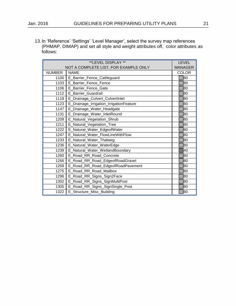
13. In ‘Reference’ ‘Settings’ ‘Level Manager’, select the survey map references (PHMAP, DIMAP) and set all style and weight attributes off, color attributes as follows:
**LEVEL DISPLAY **
NOT A COMPLETE LIST, FOR EXAMPLE ONLY
LEVEL
MANAGER
NUMBER NAME COLOR
1100 E_Barrier_Fence_Cattleguard 80
1103 E_Barrier_Fence_Fence 80
1106 E_Barrier_Fence_Gate 80
1112 E_Barrier_Guardrail 80
1118 E_Drainage_Culvert_CulvertInlet 80
1123 E_Drainage_Irrigation_IrrigationFeature 80
1147 E_Drainage_Water_Headgate 80
1131 E_Drainage_Water_InletRound 80
1209 E_Natural_Vegetation_Shrub 80
1211 E_Natural_Vegetation_Tree 80
1222 E_Natural_Water_EdgeofWater 80
1247 E_Natural_Water_FlowLineWithFlow 80
1233 E_Natural_Water_Thalweg 80
1236 E_Natural_Water_WaterEdge 80
1239 E_Natural_Water_WetlandBoundary 40
1260 E_Road_RR_Road_Concrete 80
1266 E_Road_RR_Road_EdgeofRoadGravel 80
1269 E_Road_RR_Road_EdgeofRoadPavement 80
1275 E_Road_RR_Road_Mailbox 80
1296 E_Road_RR_Signs_Sign2Face 80
1302 E_Road_RR_Signs_SignMultiPost 80
1305 E_Road_RR_Signs_SignSingle_Post 80
1322 E_Structure_Misc_Building 80
22 GUIDELINES FOR PREPARING UTILITY PLANS Jan. 2016
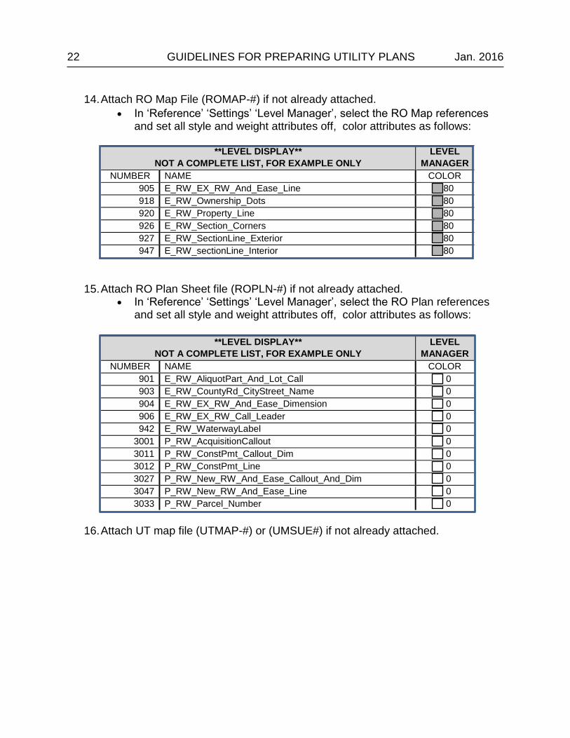
14. Attach RO Map File (ROMAP-#) if not already attached.
In ‘Reference’ ‘Settings’ ‘Level Manager’, select the RO Map references and set all style and weight attributes off, color attributes as follows:
**LEVEL DISPLAY**
NOT A COMPLETE LIST, FOR EXAMPLE ONLY
LEVEL
MANAGER
NUMBER NAME COLOR
905 E_RW_EX_RW_And_Ease_Line 80
918 E_RW_Ownership_Dots 80
920 E_RW_Property_Line 80
926 E_RW_Section_Corners 80
927 E_RW_SectionLine_Exterior 80
947 E_RW_sectionLine_Interior 80
15. Attach RO Plan Sheet file (ROPLN-#) if not already attached. In ‘Reference’ ‘Settings’ ‘Level Manager’, select the RO Plan references
and set all style and weight attributes off, color attributes as follows:
**LEVEL DISPLAY**
NOT A COMPLETE LIST, FOR EXAMPLE ONLY
LEVEL
MANAGER
NUMBER NAME COLOR
901 E_RW_AliquotPart_And_Lot_Call 0
903 E_RW_CountyRd_CityStreet_Name 0
904 E_RW_EX_RW_And_Ease_Dimension 0
906 E_RW_EX_RW_Call_Leader 0
942 E_RW_WaterwayLabel 0
3001 P_RW_AcquisitionCallout 0
3011 P_RW_ConstPmt_Callout_Dim 0
3012 P_RW_ConstPmt_Line 0
3027 P_RW_New_RW_And_Ease_Callout_And_Dim 0
3047 P_RW_New_RW_And_Ease_Line 0
3033 P_RW_Parcel_Number 0
16. Attach UT map file (UTMAP-#) or (UMSUE#) if not already attached.
Jan. 2016 GUIDELINES FOR PREPARING UTILITY PLANS 23
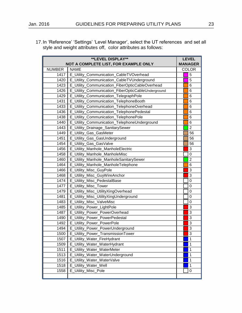
17. In ‘Reference’ ‘Settings’ ‘Level Manager’, select the UT references and set all style and weight attributes off, color attributes as follows:
**LEVEL DISPLAY**
NOT A COMPLETE LIST, FOR EXAMPLE ONLY
LEVEL
MANAGER
NUMBER NAME COLOR
1417 E_Utility_Communication_CableTVOverhead 5
1420 E_Utility_Communication_CableTVUnderground 5
1423 E_Utility_Communication_FiberOpticCableOverhead 6
1426 E_Utility_Communication_FiberOpticCableUnderground 6
1429 E_Utility_Communication_TelegraphPole 6
1431 E_Utility_Communication_TelephoneBooth 6
1433 E_Utility_Communication_TelephoneOverhead 6
1436 E_Utility_Communication_TelephonePedestal 6
1438 E_Utility_Communication_TelephonePole 6
1440 E_Utility_Communication_TelephoneUnderground 6
1443 E_Utility_Drainage_SanitarySewer 2
1449 E_Utility_Gas_GasMeter 56
1451 E_Utility_Gas_GasUnderground 56
1454 E_Utility_Gas_GasValve 56
1456 E_Utility_Manhole_ManholeElectric 3
1458 E_Utility_Manhole_ManholeMisc 0
1460 E_Utility_Manhole_ManholeSanitarySewer 2
1464 E_Utility_Manhole_ManholeTelephone 6
1466 E_Utility_Misc_GuyPole 3
1468 E_Utility_Misc_GuyWireAnchor 3
1474 E_Utility_Misc_PedestalBase 0
1477 E_Utility_Misc_Tower 0
1479 E_Utility_Misc_UtilityXingOverhead 0
1481 E_Utility_Misc_UtilityXingUnderground 0
1483 E_Utility_Misc_ValveMisc 0
1485 E_Utility_Power_LightPole 3
1487 E_Utility_Power_PowerOverhead 3
1490 E_Utility_Power_PowerPedestal 3
1492 E_Utility_Power_PowerPole 3
1494 E_Utility_Power_PowerUnderground 3
1500 E_Utility_Power_TransmissionTower 3
1507 E_Utility_Water_FireHydrant 1
1509 E_Utility_Water_WaterHydrant 1
1511 E_Utility_Water_WaterMeter 1
1513 E_Utility_Water_WaterUnderground 1
1516 E_Utility_Water_WaterValve 1
1518 E_Utility_Water_Well 1
1558 E_Utility_Misc_Pole 0
24 GUIDELINES FOR PREPARING UTILITY PLANS Jan. 2016
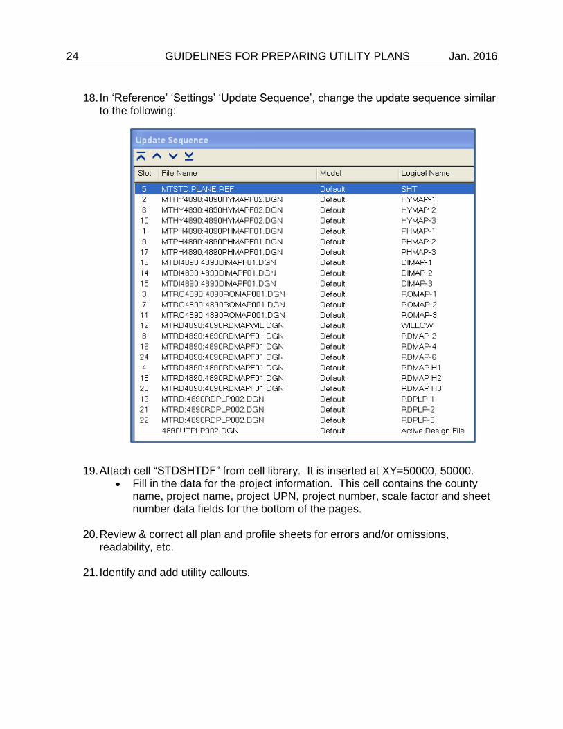
18. In ‘Reference’ ‘Settings’ ‘Update Sequence’, change the update sequence similar to the following:
19. Attach cell “STDSHTDF” from cell library. It is inserted at XY=50000, 50000. Fill in the data for the project information. This cell contains the county
name, project name, project UPN, project number, scale factor and sheet number data fields for the bottom of the pages.
20. Review & correct all plan and profile sheets for errors and/or omissions,
readability, etc.
21. Identify and add utility callouts.
Jan. 2016 GUIDELINES FOR PREPARING UTILITY PLANS 25
47-2.10 Identifying Utility Conflicts
The utilities identified as conflicts on the utility plan and profile sheets are utility conflicts
with respect to the construction limits and other construction related items. MDT’s utility
engineering specialists use the utility plans to meet with the individual utility companies
and determine the extent of each utility company’s involvement with the construction
project. Right of way, both existing and new, needs to be identified prior to the utility PIH
to determine involvement with respect to private easements, highway R/W, and room
for relocating the affected utility. Consider the following:
47-2.10.1 Lateral conflicts
Lateral conflicts are defined as those utilities that traverse laterally or parallel to the
existing roadway. The utilities involved are typically underground utilities such as
telephone, fiber cable, gas, etc. The utility can be on one side or both sides of the
roadway with various crossings. To identify the conflict:
Open utility map file (UTMAP), attach the latest road design strip map (RDMAP) with construction limits level turned on.
Identify where the utility first crosses into the construction limits then follow
the utility and determine where the utility last crosses out of the construction limits. Note whether this is left, right or on both sides of design centerline.
If the utility crosses in and out or weaves through the construction limits,
short segments can be combined into one note. As a general “rule of thumb” gaps less than 50 feet in length can be combined.
If a pedestal is located just prior to or just after the utility’s lateral conflict,
adjust the lateral conflict extending it to the pedestal or pedestals. Go to the utility plan and profile sheets and place a note indicating the
conflict on affected sheets.
47-2.10.2 Spot conflicts
Spot conflicts are defined as a conflict at a specific location. The utilities typically
involved include power, telephone, sanitary sewer, etc. and are usually poles,
pedestals, manholes etc. The conflict is called out at its’ station and offset from design
centerline. To identify the conflict:
Open the utility plan and profile sheets (UTPLP) making sure the latest
road design strip map file is attached, and with the construction limits and
road designer placed utility conflict levels turned on.
26 GUIDELINES FOR PREPARING UTILITY PLANS Jan. 2016
Visually inspect the plan sheet area for pedestals, poles etc. that are inside the construction limits. When conflicts are found place cell (“CALLLT” or “CALLRT”) from the cell library (UTILITYV8_0E) perpendicular to centerline and identify the conflict and its’ relationship to design centerline by station and offset.
Station callouts should be rounded to the nearest foot and offset distances
to the nearest tenth (0.1) foot.
47-2.10.3 Other Conflicts
Other conflicts can be defined as utilities having conflicts with the construction project
but are not defined as either a lateral or spot conflict. Examples might be a telephone
cable attached to an existing bridge that is to be replaced, or a gas line running down a
county road to be resurfaced but bid as lump sum, with construction limits not computed
or shown. These conflicts should be shown in the utility plan sheets and good judgment
exercised when defining them, either as a lateral callout or spot callout.
47-2.10.4 Utility Crossings
Utility crossings may or may not be defined as a conflict but in either case will be called
out on the utility plans. Overhead utility crossings should be called out by the station at
which the utility crosses the design centerline, the number of wires at the crossing, and
clearance measured from the centerline of the existing roadway to the lowest wire. If the
wire and clearance information is unknown it should be stated as unknown in the utility
crossing note. Underground utility crossings should be called out by station at which the
utility crosses the design centerline, depth the utility is buried from the existing roadway
to the top of the utility and number of wires or cables if known. Underground gas, water,
sewer, duct systems etc. should include the station the utility crosses design centerline,
depth the utility is buried from the existing roadway to the top of utility and also include
the size of utility if known. See CADD standards for correct placement of utility crossing
notes. Utility crossings also need to be depicted visually on the cross sections.
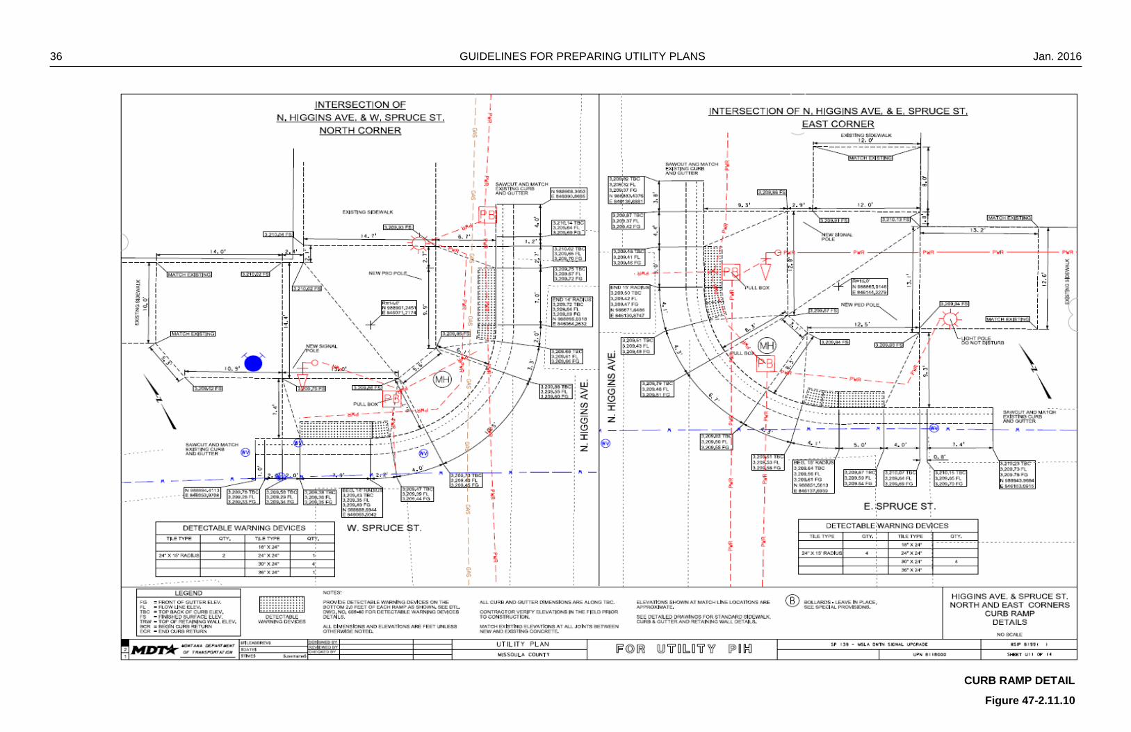
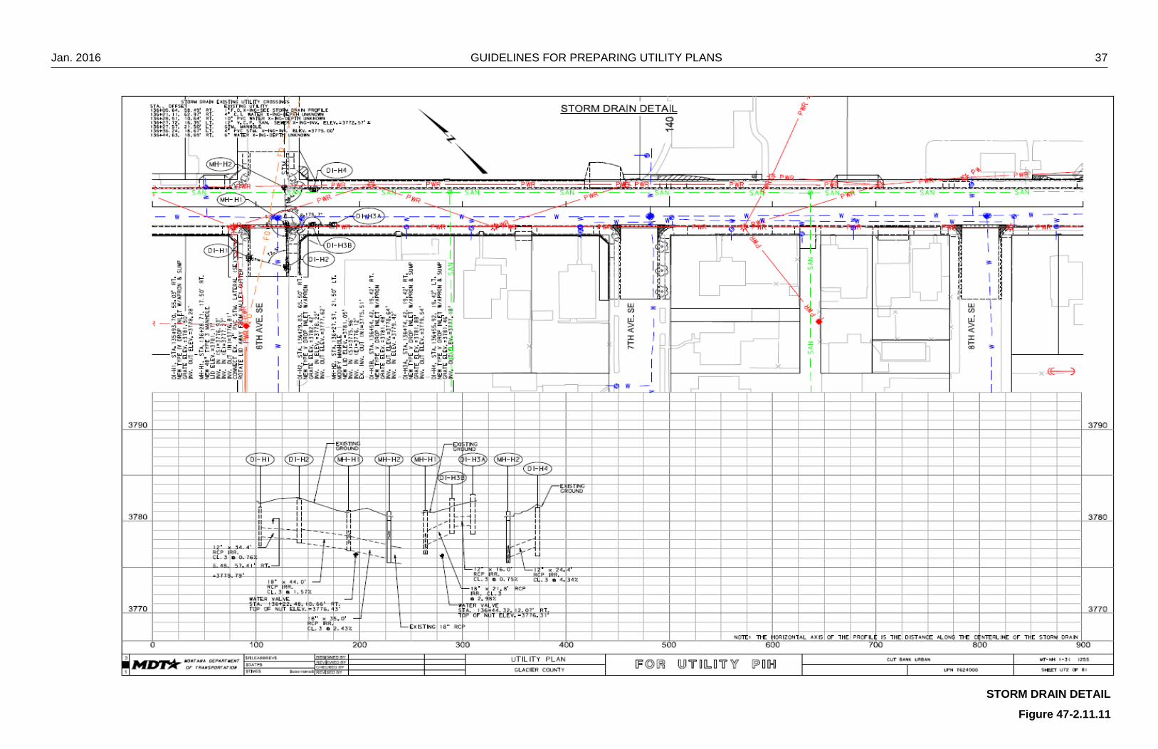
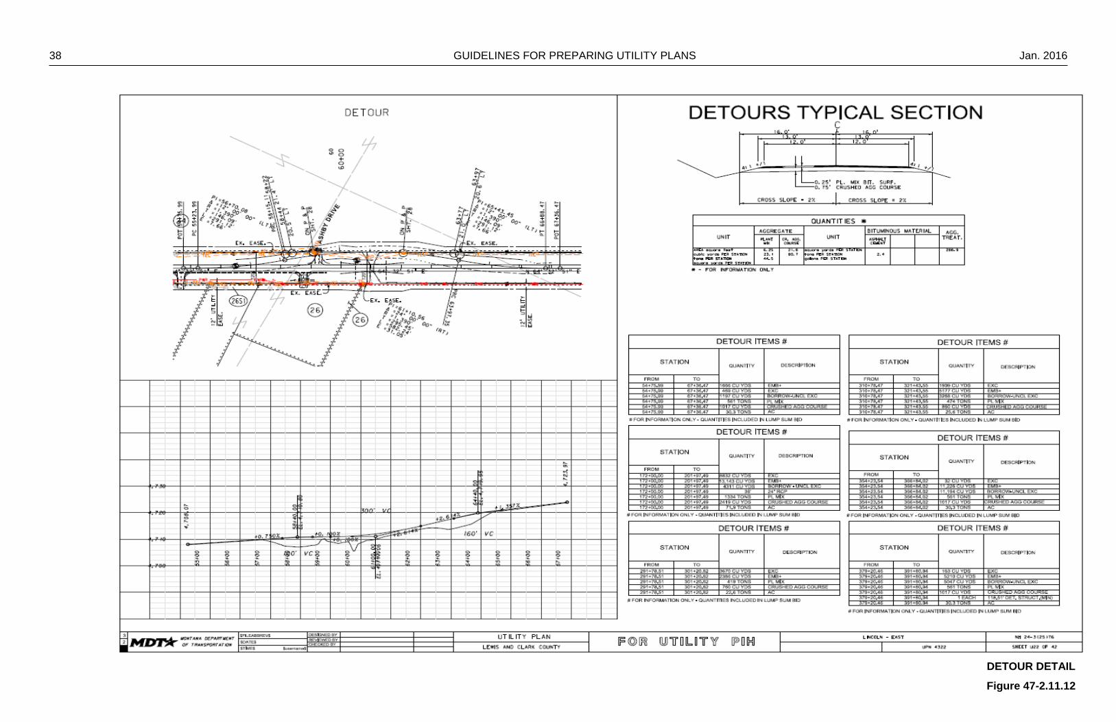
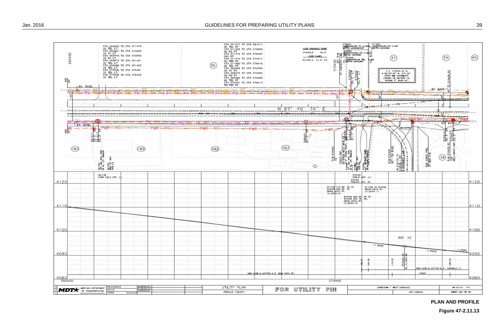
47-2.11 Example Plan Sheets
The following figures (11 in X 17 in sheets) are provided as a visual aid for the
preparation of the utility plans package. They are from various projects and are
representative of a typical utility plans package.

Jan. 2016 GUIDELINES FOR PREPARING UTILITY PLANS 27
TITLE
Figure 47-2.11.1
28 GUIDELINES FOR PREPARING UTILITY PLANS Jan. 2016
TABLE OF CONTENTS, NOTES
Figure 47-2.11.2
Jan. 2016 GUIDELINES FOR PREPARING UTILITY PLANS 29
CONTROL DIAGRAM
Figure 47-2.11.3

30 GUIDELINES FOR PREPARING UTILITY PLANS Jan. 2016
OWNERSHIP
Figure 47-2.11.4
Jan. 2016 GUIDELINES FOR PREPARING UTILITY PLANS 31
TYPICAL SECTIONS
Figure 47-2.11.5
32 GUIDELINES FOR PREPARING UTILITY PLANS Jan. 2016
SUMMARY-1
Figure 47-2.11.6
Jan. 2016 GUIDELINES FOR PREPARING UTILITY PLANS 33
SUMMARY-2
Figure 47-2.11.7

34 GUIDELINES FOR PREPARING UTILITY PLANS Jan. 2016
DETAIL
Figure 47-2.11.8
Jan. 2016 GUIDELINES FOR PREPARING UTILITY PLANS 35
PLAN AND PROFILE DETAIL
Figure 47-2.11.9
36 GUIDELINES FOR PREPARING UTILITY PLANS Jan. 2016
CURB RAMP DETAIL
Figure 47-2.11.10
Jan. 2016 GUIDELINES FOR PREPARING UTILITY PLANS 37
STORM DRAIN DETAIL
Figure 47-2.11.11
38 GUIDELINES FOR PREPARING UTILITY PLANS Jan. 2016
DETOUR DETAIL
Figure 47-2.11.12
Jan. 2016 GUIDELINES FOR PREPARING UTILITY PLANS 39
PLAN AND PROFILE
Figure 47-2.11.13
40 GUIDELINES FOR PREPARING UTILITY PLANS Jan. 2016
BRIDGE GENERAL LAYOUT
Figure 47-2.11.14