chapter 4 – construction and maintenance 4 - construction... · chapter 4 – construction and...
TRANSCRIPT

Surface Operating Standards and Guidelines for Oil and Gas Exploration and Development ��
Chapter 4 – Construction and Maintenance
This chapter provides guidance for the operator
about the basic requirements for safe and envi-
ronmentally sound construction and maintenance
of oil and gas-related infrastructure. Construction
and maintenance must be performed to standards
that ensure the long-term health and productivity
of the land. The operator’s representative must
ensure compliance with all plans and designs.
The representative should be designated prior to
construction; be accessible to the surface
management agency authorized officer; have immedi-ate access to an approved copy of the Application for Permit to Drill (APD), including all maps, drawings, templates, and construction standards; and have the authority to make changes at the request or order of the BLM or surface management agency.
Well SitesSite Selection and Design
To the extent permitted by the geologic target, well spacing, and drilling and production technology, the locations selected for well sites, tank batteries, pits, and compressor stations should be planned so as to minimize long-term disruption of the surface resources and existing uses, and to promote success-ful reclamation. Design and construction techniques and other practices should be employed that would minimize surface disturbance and the associated effects of proposed operations and maintain the reclamation potential of the site. The following guidelines can be used to assist in meeting these objectives and reducing the overall undesirable impacts from well sites and other construction areas.
Well sites should be designed to fit the landscape and minimize construction needs. In many cases, this
means designing a well site that has an irregular shape, not rectangular. The site layout should be located and staked in the most level area, off narrow ridges, and set back from steep slopes, while taking into consideration the geologic target, technical, economic, and operational feasibility, spacing rules, natural resource concerns, and safety considerations. Well locations constructed on steep slopes cost more to construct, maintain, and reclaim and result in greater resource impacts. Locations on steep slopes that require deep, nearly vertical cuts and steep fill slopes should be avoided where possible or appropriately mitigated. Operations should also be avoided or properly mitigated in riparian areas, floodplains, playas, lakeshores, wetlands, and areas subject to severe erosion and mass soil movement. In visually sensitive areas, locations should be selected that provide for vegetative and topographic screening. The well site or production facility location should also be reviewed to determine its effect on the location of the access road. The advantages gained by a good well site or tank battery location should not be negated by the adverse effects of the access road location.

�� Surface Operating Standards and Guidelines for Oil and Gas Exploration and Development
ConstructionConstruction procedures must conform to the
approved Surface Use Plan of Operations. In order to minimize surface disturbance, construction equipment appropriately sized to the scope and scale of the proposed operation should be used. All surface soil materials (topsoil) are to be removed from the entire cut and fill area and temporarily stockpiled for reuse during interim reclamation or final reclamation if the well is a dry hole. The depth of topsoil to be removed and stockpiled should be determined at the onsite inspection and should be stated either in the proposed Surface Use Plan of Operations or specified in the APD conditions of approval.
Topsoil should be segregated and stored separately from subsurface materials to avoid mixing during construction, storage, and interim reclamation. Subsurface materials should never be placed on top of topsoil material at any point in the operation. Stockpiles should be located and protected so that wind and water erosion are minimized and reclamation potential is maximized.
Excavation of the cut and fill slopes is normally guided by information on the slope stakes. Fills should be compacted to minimize the chance of subsidence or slope failure. If excess cut material exists after fill areas have been brought to grade, the excess material will be stockpiled at approved locations. Snow and frozen soil material is not to be used in construction of fill areas, dikes, or berms. To reduce areas of soil disturbance, the surface management agency may allow mowing or brush beating of vegetation for parts of the well location or access road where excavation is not necessary.
The area of the well pad where the drilling rig substructure is located should be level and
capable of supporting the rig. The drill rig, tanks, heater-treater, and other production equipment are not to be placed on uncompacted fill material. The area used for mud tanks, generators, mud storage, and fuel tanks should be at a slight slope, where possible, or a suitable alternative, such as ditching, should be used to provide surface drainage from the work area to the pit.
To reduce erosion and soil loss, it may be appropriate to divert storm water away from the well location with ditches, berms, or waterbars above the cut slopes and to trap well location runoff and sediments on or near the location through the use of sediment fences or water retention ponds.
Reserve PitsReserve pits are generally used for storage or
disposal of water, drill mud, and cuttings during drilling operations. The pit should normally be located entirely in cut material. Avoid constructing reserve pits in areas of shallow groundwater. Reserve pits should not be constructed in natural watercourses. Water courses include lake beds, gullies, draws, streambeds, washes, arroyos, or channels that are delineated on a 1:24,000 USGS quadrangle map or have a hydrologic connection to streams, rivers, or lakes.
For reserve pit construction on sloping sites, the preferred method is to locate the pit on the drill pad next to the high wall. Pits are constructed totally in cut at such locations. If this is not possible, at least 50 percent of the reserve pit should be constructed below original ground level to help prevent failure of the pit dike. Fill dikes should be properly compacted in lifts. The necessary degree of compaction depends on soil texture and moisture content. The pit should

��Surface Operating Standards and Guidelines for Oil and Gas Exploration and Development
be designed to contain all anticipated drilling muds, cuttings, fracture fluids, and precipitation while maintaining at least 2 feet of freeboard.
Pits improperly constructed on slopes or poor soil types may leak along the plane between the natural ground level and the fill. There is a significant potential for pit failure in these situations. When constructing dikes for pits or impoundments with fill embankment, a keyway or core trench should be excavated to a minimum depth of 2 to 3 feet below the original ground level. The core of the embankment can then be constructed with compacted, water-impervious material.
To prevent contamination of ground water and soils or to conserve water, it is recommended that operators use a closed-loop drilling system or line reserve pits with an impermeable liner, particularly when it is anticipated that pits will contain moderate or high levels of hydrocarbons and chloride, or the pits are located in areas of shallow groundwater or porous soils over fractured bedrock aquifers.
Pits can be lined with synthetic liners or other materials such as bentonite or clay. Impermeable liners should have a permeability of less than 10-7cm/sec. Liners must be installed so that they will not leak and must be composed of materials compatible with all substances to be placed in the pit. Synthetic liners with a minimum thickness of 12 mils and resistance to ultraviolet radiation,
weathering, chemicals, punctures, and tearing are most commonly used, although some States may require liners that are thicker. Suitable bedding material, such as sand, clay, or felt liners should be used in areas where the base rock might puncture the liner.
Depending on the proposed contents of the pit and sensitivity of the environment, the surface management agency may require a leak detection system or the use of self-contained mud systems with the drilling fluids, mud, and cuttings being transported to approved disposal areas.
Reserve pits should be appropriately fenced to prevent access by persons, wildlife, or livestock. During drilling in active livestock areas, the reserve pit must be fenced with an exclosure fence on three sides and then fenced on the fourth side once drilling has been completed. Refer to Figure 1 for recommended fence construction standards in active livestock areas. In areas where livestock will not be present, other types of fences may be appropriate.
The fence should remain in place until pit reclamation begins. After cessation of drilling and completion operations, any visible or measurable layer of oil must be removed from the surface of the reserve pit and the pit kept free of oil. In some situations and locations, precautions, such as netting, may be required in order to prevent access and mortality of birds and other animals.

Surface Operating Standards and Guidelines for Oil and Gas Exploration and Development��
Figure 1. Recommended construction standards for exclosure fences in livestock areas.
see mortise detail
7' minimum 7' minimum
9 – ga. smooth galv. wire
line post(wood or steel)
Add a rock deadman (min. weight 50 lbs.) whenspace between bottom wire and ground exceeds 20"
L
7' minimum 7' minimum
7' minimum
twisted wire or wood stay
wood line post
1"
1"
spike (spikingor toe nailingas specified)
L
42"
7' minimum brace
spike
Mortise Detail
Line Panels
Stress Panel Panel at Minor Depression
End Panel–Type 1 End Panel–Type 2
steel linepost

Surface Operating Standards and Guidelines for Oil and Gas Exploration and Development ��
Roads and Access WaysThis section provides the minimum guidelines
for oil and gas operators on BLM and FS policy and standards relative to the planning, location, design, construction, maintenance, and operation of roads and access ways on public and National Forest
System lands. Contact the local BLM or FS office for specific requirements. Exception to or modification of these guidelines is at the surface management agency’s discretion based on the physical conditions at the site and the project proposal. Figure 2 illustrates commonly used terms in road design and should be referred to when reviewing this section.
right-of-way
Note: Shapes and dimensions will vary to fit local conditions
See drawings for typical sections
x and y denote clearing outside of roadway
rig
ht-
of-
way
lin
e
rig
ht-
of-
way
lin
e
clea
rin
g li
mit
clea
rin
glim
it clearing width
roadwayx y
roadside roadside
traveledway
ground line
black slope(cut slope)
drainage ditch
roadbedfill slope
surfacecourse
base course
subgrade
sho
uld
er
sho
uld
er
To ensure public safety and the protection of Federal resources, BLM and FS roads must be constructed to an appropriate standard no higher than necessary to accommodate the intended use. In many cases, the construction of a lower-class road will meet the operator’s access needs, while minimizing the effects on other important resource values.
Roads used to access oil and gas locations are typically constructed for that primary purpose, are rarely permanent, and exist only as long as necessary to complete exploration and production operations. They are authorized with an accompanying
reclamation plan and are to be reclaimed after well and field operations are completed. In relatively rare cases, the surface management agency or surface owner may assume responsibility for the continued operation and maintenance of roads deemed necessary.
The authorized officer has the option of determining whether professional engineering design and construction oversight is necessary or whether the road can be constructed by the operator consistent with site-specific standards and approved road design templates (Figures 2 and 3). The need for professional engineering design and oversight should be based on factors such as topography,
Figure 2. Illustration of commonly used terms in road design
Surface Operating Standards and Guidelines for Oil and Gas Exploration and Development�0
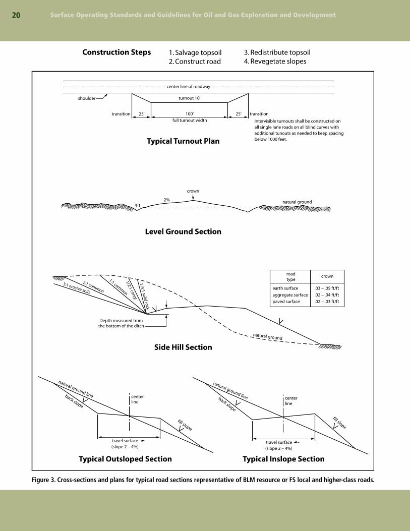
Figure 3. Cross-sections and plans for typical road sections representative of BLM resource or FS local and higher-class roads.
Typical Turnout Plan
Level Ground Section
Side Hill Section
transition transition
Intervisible turnouts shall be constructed onall single lane roads on all blind curves withadditional tunouts as needed to keep spacingbelow 1000 feet.
Depth measured fromthe bottom of the ditch
1. Salvage topsoil2. Construct road
shoulder
center line of roadway
25' 25'100'
turnout 10'
full turnout width
natural ground
crown
natural ground
3:1 erosive soils
3:1
2:1 common
1:1 common
1/2:1 congl1/4:1 solid
rock
roadtype
crown
earth surface
aggregate surface
paved surface
.03 – .05 ft/ft
.02 – .04 ft/ft
.02 – .03 ft/ft
Typical Outsloped Section
natural ground lineback slope
fill slope
centerline
travel surface(slope 2 – 4%)
Typical Inslope Section
natural ground lineback slope
fill slope
centerline
travel surface(slope 2 – 4%)
2%
Construction Steps 3. Redistribute topsoil4. Revegetate slopes

��Surface Operating Standards and Guidelines for Oil and Gas Exploration and Development
soils, hydrology, safety, and levels and types of use by the operator and general public. For oil and gas roads on National Forest System lands, a qualified FS engineer reviews all project design drawings, officially attesting to their technical adequacy.
To meet the requirements of Onshore Order No. 1 (Surface Use Plan of Operations, 2a and b) for new or reconstructed roads, the operator must provide information such as:
n Road width, maximum grade, and crown design
n Location of turnouts
n Plans for soils-, hydrology-, and topography-dependent drainage, including ditches and locations and sizes of culverts and bridges
n On- and off-site erosion control
n Plans for revegetation of disturbed areas
n Fence cuts and cattle guards
n Major cuts and fills
n Source and storage sites for topsoil
n Types of surfacing materials, if any
n Plans for maintaining or improving existing roads
All roads must be designed, constructed, and maintained by the operator in a safe and environmentally responsible manner. Oil and gas roads that are not closed to public use (through the use of gates or other traffic control devices) have the potential to serve secondary uses, such as providing access for hunters and other recreational users who may not be familiar with the road and area. Therefore, safety is a primary design consideration.
Roads also have the potential to cause environmental harm through erosion, air pollution, stream degradation, habitat alteration, and increased public use of an area. Careful attention to the proposed road location and design can significantly minimize environmental harm. For example, shorter roads constructed on steep slopes may cost more to construct, maintain, and reclaim and can also result in greater environmental impacts than would longer roads constructed along the contours of the land or constructed in flatter terrain. In areas of high environmental sensitivity, special road location, design, and construction and
maintenance techniques may be required, as well as seasonal vehicular closures to the general public.
It is always a good practice to consult with the surface management agency or private landowner prior to submitting the road design. Helpful design information can also be found on agency websites. For the BLM, guidance can be found in BLM 9113–Roads Manual; and BLM 9130–Sign Manual. For the FS, information is available in EM-7100-15: Sign and Poster Guidelines for the FS or the FS Water/Road Interaction Series of publications.
Transportation PlanningThe goal of transportation planning is to
identify and analyze feasible alternatives for access that meet the objectives of the surface management agency, private surface owner, and the needs of the diverse users of Federal lands. The transportation planning process:
n Considers future road use needs, including public access and resource development or use
n Considers affected resource values and safety
n Avoids haphazard or unnecessary development of roads and utility corridors
Road location and design criteria are also developed and documented during the transportation planning process. Transportation planning can prevent unnecessary expenditures of time and money and prevent unnecessary surface disturbance. Therefore, it is important for the operator to become involved in the transportation planning process.
Road LocationRoad location is critical to the long-term
maintenance and environmental success of a road construction project. Proper road location can significantly reduce or eliminate impacts to cultural, scenic, biological, and other environmental resources. Operators are strongly encouraged to contact the surface management agency or private surface owner about possible route locations before survey-ing and staking. This early communication between the operator and the surface management agency or private surface owner can minimize changes made at the onsite inspection and reduce project delays.
�� Surface Operating Standards and Guidelines for Oil and Gas Exploration and Development
Existing roads should be considered for use as access routes and may be used when they meet agency standards, transportation and development needs, and environmental objectives. When access involves the use of existing agency roads, operators must obtain agency approval and may be required to upgrade the roads, contribute to road maintenance funds, or participate in road maintenance agreements.
When selecting a location for new roads, consider following topographic contours. While laying out roads in a point-to-point approach minimizes the length of road, it often increases soil erosion, maintenance costs, long-term loss of vegetation, and visual contrast. Following natural topographic contours preserves natural drainage patterns and usually makes it possible to design a more aesthetically pleasing road with lower construction, maintenance, and reclamation costs and less impact on the environment.
Initial steps in road location include:
n Determination of the intended use of the road, planned season of use, type of vehicles to be used, road class, and needs of the surface owner or agency
n Examination of the surface management agency’s transportation plan, which may already have identified feasible routes for the area
n Examination of existing data, including maps and aerial photos, land use plan decisions, and biological, physical, and cultural conditions of the area
n Determination of oil and gas lease obligations, future development needs, and safety considerations.
Once these steps have been taken, an appropriate route can be identified. This process is critical to ensuring that the safest and least intrusive route is chosen.
Geotechnical FactorsIn complex terrain or conditions, it is
recommended that the operator look at various route alternatives before selecting the preferred route. Field reconnaissance of alternative routes may be necessary in order to provide information on such factors as soil types, construction/reclamation
limitations, type of excavation, landslide areas, subgrade conditions indicating the need for surfacing, potential cut slope problems, surface or subsurface water problem areas, suitability of fill material, potential gravel pits or quarries for road aggregate, and potential borrow and waste sites. A good road location analysis may avoid costly problems and identify cost-saving opportunities.
Other FactorsOther factors to consider that are unique to the
oil and gas industry include:
n The potential for encountering sour gas (H2S). Note the prevailing wind direction and identify a clear escape route from the drill site.
n The potential for year-round operation. Drill sites and producing locations may require all-weather access and special maintenance considerations for snow removal.
n The potential for exploratory drilling to result in a producing operation. Select initial road alignments and road classes based on the potential for upgrade if the wells are completed for production.
When the road location information is submitted to the surface management agency, the acceptability of the proposed route, and if applicable, alternative routes, can be evaluated. The preferred road location will be identified by the authorized officer at the onsite inspection in coordination with the private surface owner on non-Federal surface.
Road Design and ConstructionConstruction and Reclamation Considerations
New road construction or reconstruction by the operator must be suitable for the intended use and must comply with BLM road and safety standards, such as those found in BLM’s 9113–Roads Manual. Roads constructed within the jurisdiction of the FS must comply with applicable FS road and safety standards.
Roads should be designed and constructed to allow for successful interim and eventual final

Surface Operating Standards and Guidelines for Oil and Gas Exploration and Development ��
reclamation. Revegetation of road ditches and cut and fill slopes will help stabilize exposed soils and reduce sediment loss, reduce the growth of noxious weeds, reduce maintenance costs, maintain scenic quality and forage, and protect habitat. To ensure successful growth of plants and forbs, topsoil must be salvaged where available during road construction and respread to the greatest degree practical on cut slopes, fill slopes, and borrow ditches prior to seeding. To ensure the stability of freshly topsoiled slopes during revegetation, the application of mulch or other sediment control measures may be appropriate.
Construction with saturated or frozen soils results in unstable roads and should be avoided. Vehicular travel under wet conditions can produce significant rutting of unsurfaced roads resulting in soil loss and safety concerns. If road use is anticipated during saturated soil conditions, the surface manage- ment agency may require road surfacing to provide safe vehicle access, ensure uninterrupted operations, and reduce road damage and sediment loss.
Nonconstructed Roads and RoutesWhen site conditions are appropriate, the
surface management agency may approve the creation or use of “primitive,” two-track roads or overland route corridors to meet the operator’s access needs. Primitive roads and route corridors
may serve as appropriate access to exploration drilling locations where it is not certain if the well will be productive, or to producing wells where vehicle traffic is infrequent due to the use of off-site production facilities and automated well monitoring.
The appropriateness of primitive roads or routes is both site-specific and use-specific and is typically based on many factors, such as anticipated dry or frozen soil conditions, seasonal weather conditions, flat terrain, low anticipated traffic, or driller’s or operator’s access needs. Primitive roads or routes necessitate low vehicle speed and are typically limited to four-wheel drive or high clearance vehicles. They can consist of existing or new roads with minor or moderate grading; two-track roads created by the operator’s direct vehicle use with little or no grading; overland routes within a defined travel corridor leaving no defined roadway beyond crushed vegetation; or any combination along the route. Operators should not flat-blade roads. Drainage must be maintained, where appropriate, to avoid erosion or the creation of a muddy, braided road.
These roads and routes must be used and maintained in a safe and environmentally responsible manner and are not intended for use as all-weather access roads. Resource damage must be repaired as soon as possible and the operator must consult with the surface management agency
A minimum disturbance, primitive,
two-track road winds its way to a
drilling operation. To further reduce
disturbance, most of the well
location has not been stripped of
vegetation or topsoil.

Surface Operating Standards and Guidelines for Oil and Gas Exploration and Development�4
to determine if all or a portion of the road needs to be upgraded to an all-weather access road. When used and maintained appropriately, nonconstructed roads and routes have the advantage of reducing construction, maintenance, and reclamation costs and reducing resource impacts. The use of nonconstructed roads must be approved by the surface management agency.
Constructed RoadsThe surface management agency determines the
appropriate road type and associated road design standards based on the expected traffic volume and other factors, such as seasonal or year-round use, the design vehicle, soil types, rainfall, topography, construction costs, compatibility with other resource values, and safety. This information is documented during the transportation planning process and onsite meeting. Road types may vary along the same route depending on the operator’s or the surface management agency’s access or resource protection needs. In some cases, exploration drilling may warrant a lower design standard or primitive road, mentioned previously, which could be upgraded if the well becomes a producing well.
BLM Resource or FS Local RoadsBLM resource or FS local roads are low-
volume, single-lane roads. They normally have a 12 to14 foot travelway with “intervisible turnouts,” as appropriate, where approaching drivers have
a clear view of the section of road between the two turnouts and can pull off to the side to let the approaching driver pass. They are usually used for dry weather, but may be surfaced, drained, and maintained for all-weather use. These roads connect terminal facilities, such as a well site, to collector, local, arterial, or other higher-class roads. They serve low average daily traffic (ADT) and are located on the basis of the specific resource activity need rather than travel efficiency.
BLM Local or FS Collector RoadsBLM local or FS collector roads may be single-
lane or double-lane with travelways 12 to 24 feet in width and intervisible turnouts. They are normally graded, drained, and surfaced and are capable of carrying highway loads. These roads provide access to large areas and for various uses. They collect traffic from resource or local roads or terminal facilities and are connected to arterial roads or public highways. The location and standards for these roads are based on both long-term resource needs and travel efficiency. They may be operated for either constant or inter-mittent service, depending on land use and resource management objectives for the area being served.
BLM Collector or FS Arterial RoadsBLM collector or FS arterial roads are usually
double-lane, graded, drained and surfaced, with a 20 to 24 foot travelway. They serve large land areas and are the major access route into development areas
General Design Specificationsfor Different Types of Roads
Definitions
Design Criteria are requirements that govern the selection of elements and standards for a road, such as
resource management objectives, road management objectives, safety requirements, and traffic characteristics.
Design Elements are the physical characteristics of a road, such as the ditches, culverts, travelway clearing limits,
curve widening, slopes, and drainage characteristics that, when combined, comprise the planned facility.
Design Standards comprise the lengths, widths, and depths of design elements, such as a 14-foot-wide travelway,
2-foot shoulders, 2:1 cut slopes, 3-foot curve widening, and 6 inches of crushed aggregate. Design terms are
illustrated in Figure 2.
Design Vehicle is the vehicle most frequently using the road that determines the minimum standard for a
particular design element. No single vehicle, however, controls the standards for all the design elements for a road.
��Surface Operating Standards and Guidelines for Oil and Gas Exploration and Development
with high average daily traffic rates. The locations and standards are often determined by a demand for maximum mobility and travel efficiency rather than a specific resource management service. They usually connect with public highways or other arterials to form an integrated network of primary travel routes and are operated for long-term land and resource management purposes and constant service.
BLM Resource and FS Local Roads
Basic Design RequirementsThe surface management agency will provide
requirements specific to proposed oil and gas roads during project planning and/or at the onsite review with consideration of safety, impacts on land and resources, and cost of transportation. Requirements for specific proposals may vary somewhat from the generalized requirements that follow.
• Design speed specific to oil and gas roads is 10 to 30 miles per hour. For the FS, this should generally be less than 15 miles per hour.
• Preferred travelway width is 14 feet with turnouts. For the FS, this can vary from two parallel vehicle tracks, bladed 12-foot sections with turnouts, or a broader defined overland corridor approved by the surface management agency.
• Recommended minimum horizontal curve radii is determined by the design vehicle and design speed. Where terrain will not allow the proper curve radii, curve widening is necessary. Specifications are available from the surface management agency.
• Road gradient has a major effect on the environ-mental and visual impact of a road, particularly in terms of erosion. The gradient should fit as closely as possible to the natural terrain, considering vehicle operational limitations, soil types, environ-mental constraints, and traffic service levels. The gradient should not exceed 8 percent except for pitch grades (300 feet or less in length) in order to minimize environmental effects. In mountainous or dissected terrain, grades greater than 8 percent up to 16 percent may be permissible with prior approval of the surface management agency.
• The primary purpose of turnouts is for user convenience and safety and to maintain user
speed. Turnouts are generally naturally occurring, such as additional widths on ridges or other available areas on flat terrain. On roads open to the public, turnouts must be located at 1,000-foot intervals or be intervisible, whichever is less.
• Drainage control must be ensured over the entire road through the use of drainage dips, insloping, natural rolling topography, ditch turnouts, ditches, or culverts. Ditches and culverts may be required in some situations, depending on grades, soils, and local hydrology. If culverts or drainage crossings are needed, they should be designed for a 25-year or greater storm frequency, without development of a static head at the pipe inlet.
• Gravel or other surfacing is not always required, but may be necessary for “soft” road sections, steep grades, highly erosive soils, clay soils, or where all-weather access is needed.
• At times, a limited number of oil field vehicles (critical vehicles) larger than the design vehicle may make occasional use of the road. The operator should consider these needs in road design.
Field Survey RequirementsField survey requirements vary with topography,
geologic hazard, potential for public and recreational use, or other concerns. Each surface management agency has survey requirements based on design requirements and concerns specific to the area. The surface management agency should be contacted as early as possible to determine the survey requirements. The following general requirements are imposed to control work and produce the desired road.
• A flagline is established along the construction route. Flags should be placed approximately every 100 feet, or be intervisible, whichever is less.
• Construction control staking may be required depending on conditions of the site.
• Culvert installations are located and staked.
Design Drawings and Templates• On side slopes of 0 to 20 percent, where horizontal
and vertical alignment can be worked out on the ground, a plan and profile drawing may not be required. Standard templates, drainage dip spacing,

�� Surface Operating Standards and Guidelines for Oil and Gas Exploration and Development
culvert locations, and turnout spacing guides would be acceptable.
• A plan and profile view would be the minimum drawing required on steeper slopes and in areas of environmental concern. The drawing should identify grade, alignment, stationing, turnouts, and culvert locations.
• Standard templates of road cross-sections and drainage dips are required for all resource, local, and higher-class roads. Figures 2 and 3 illustrate these sections.
• Additional information may be required in areas of environmental or engineering concern.
ConstructionThe operator must take all necessary precautions
for protection of the work and safety of the public during construction of the road. Warning signs must be posted during blasting operations.
Clearing and GrubbingClearing and grubbing will normally be required
on all sections of the road. Exceptions would be allowed in areas of sparse, non-woody vegetation.
All clearing and grubbing should be confined to a specified clearing width (Figure 2), which is usually somewhat wider than the limits of actual construction (roadway). Branches of all trees extending over the roadbed should be trimmed to provide a clear height of 14 feet above the roadbed surface. All vegetative debris must be disposed of as specified by the surface management agency.
ExcavationAll soil material and fragmented rock
removed in excavation is to be used as directed in the approved plan. Excess cut material shall not be wasted unless specified in the approved plan.
Roadbed ConstructionRoadbed material should not be placed when
the materials or the surface are frozen or too wet for satisfactory compaction. Equipment should be routed over the layers of roadbed material already in place to help avoid uneven compaction anywhere along the travel route. Borrow material
shall not be used until material from roadway excavation has been placed in the embankments, unless otherwise permitted. Borrow areas used by the operator must be approved prior to the start of excavation.
Roadside ditches should conform to the slope, grade, and shape of the required cross-section with no projections of roots, stumps, rocks, or similar debris. Side ditches must be excavated to a depth of 1-foot minimum below the finished road surface. Drainage turnout spacing on these ditches should not exceed 500 feet; slopes greater than 5 percent may require closer spacing of turnout furrows (wing ditches or relief ditches).
BLM Local and FS Collector Roads
Basic Design Requirements• Design speed is generally 15 to 50 miles per
hour. For the FS, it is 15 to 25 miles per hour. The selected design speed establishes the minimum sight distance for stopping and passing, and road geometrics such as minimum radius of curvature, the gradient, and type of running surface.
• Travelway minimum is 14 feet (single lane) and 24 feet (double lane) with intervisible turnouts, as may be required.
• Recommended minimum horizontal curve radius is 220 feet. Where terrain will not allow 220-foot curve radii, curve widening is necessary. Super-elevation should be considered at speeds greater than 20 miles per hour. Specifications are available from surface management agency engineering offices.
• Vertical curves should be designed with an appropriate “k” value (rate of vertical curvature length per percent of “A”, the algebraic difference in grade) based on design speed (for example on FS, crest vertical curves, 30 mph k=9; 40 mph k=22; 50 mph k = 45).
• Maximum grades should not exceed 8 percent. Pitch grades for lengths not to exceed 300 feet may be allowed to exceed 8 percent in some cases.
• All culverts must be sized in accordance with accepted engineering practices and any special environmental concerns. The minimum size culvert in any installation is 18 inches. Drainage crossings
��Surface Operating Standards and Guidelines for Oil and Gas Exploration and Development
and culverts should be designed for a 25-year or greater storm frequency and allow fish passage in perennial streams where fish are present.
• Turnouts are required on all single-lane roads. Turnouts must be located at 1000-foot intervals or be intervisible, whichever is less. The length should not be less than 100 feet, with additional 50-foot transitional tapers at each end.
• Surfacing may be required to provide all-weather access. If surfacing is needed, aggregate size, type, amount, and application method will be specified by the local office of the surface management agency. Subgrade analysis may be required to determine load-bearing capacities.
Field Survey RequirementsGenerally, the survey requirements for these
roads are similar to those for BLM resource and FS local roads. These roads, however, are designed for higher average daily traffic rates and greater speeds. Thus, in addition to flagline and culvert survey requirements, an instrument or topographic survey with preliminary centerline staking and slope staking is usually required on steep terrain and in areas requiring special engineering. Specific survey requirements are available at the local office of the surface management agency.
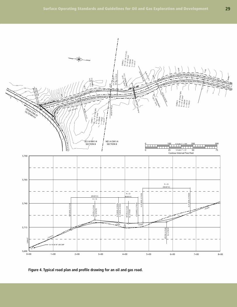
Design Drawings and Templates• Generally, the required drawings for this road
class would include a plan and profile (Figure 4). The drawing should identify grade, location, stationing, surfacing, turnouts, culvert locations, and drainage dip spacing.
• Standard templates of the proposed road cross-section(s) (Figures 2 and 3) and drainage dip design are required for this type of road.
• Additional information may be required in areas of environmental or engineering concern.
Construction• Drainage dips, construction, and spacing are the
same as for BLM resource and FS local roads.
• Culvert cross-drains should be used in lieu of drainage dips for road grades in excess of 10 percent. Culvert installation is discussed in the Drainage and Drainage Structure Section.
• Construction standards are the same as given in the BLM Resource and FS Local Roads Section.
BLM Collector and FS Arterial Roads
Basic Survey and Design Requirements• Vertical, horizontal, and topographic data, as
well as significant features should be plotted on standard plan and profile sheets to a scale of 1 inch = 100 feet horizontal and 1 inch = 20 feet vertical, or as otherwise directed by the surface management agency. The design shall conform to the most current edition of the AASHTO, Guide-lines for Geometric Design of Very Low-Volume Local Roads, for access roads with an anticipated average daily traffic of less than 400 vehicles.
• Plot “L” (layout) line along “P” (preliminary) line using the following design standards criteria:
- Design speed is 30 miles per hour or greater unless otherwise directed.
- Travel width-minimum is 20 feet, maximum is 24 feet.
- Minimum horizontal curve radius is 460 feet unless shorter radii are approved. The curve radius must take into account super-elevation.
- Design vertical curves with an appropriate “k” value based on design speed.
- Maximum grade is 8 percent (except pitch grades not exceeding 300 feet in length and 10 percent in grade).
- Mass diagrams and earthwork balancing may be required. Obvious areas of waste or borrow shall be noted on the plan and profile as well as proposed locations of borrow or waste disposal areas.
- All culverts should be designed for a minimum 25-year storm frequency with an allowable head that does not overlap the roadway or cause damage. However, the minimum acceptable size culvert diameter is 18 inches. Show all culverts planned to accurate vertical scale on plan profile sheets.
- Slope staking is required.

�� Surface Operating Standards and Guidelines for Oil and Gas Exploration and Development
Design Drawings and Templates• Complete plan and profile drawings are required
for any BLM collector or FS arterial road (Figure 4). These drawings should identify grade, location, stationing, and all culvert sizes and locations (see Figure 7 for examples).
• Standard templates of road cross-sections, drainage design, and culvert location and installation are required (Examples in Figures 3 through 6).
• Mass diagrams and materials investigation and classification may be required.
ConstructionExcept for the specific items that follow,
construction standards are given in the BLM Resource/FS Roads or the BLM Local/FS Collector Roads Sections. Construction shall be performed under the direction of a licensed, professional engineer as required by the BLM, or a qualified engineer for roads on FS lands.
Excavation and fill construction will be performed to secure the greatest practicable degree of roadbed compaction and stability. Roadbed
materials shall be placed parallel to the axis of the roadway in even, continuous, approximately horizontal layers not more than 8 inches in thickness. The full cross-section of the fill must be maintained as each successive layer is placed. Place successive layers of material on embankment areas to produce the best practical distribution of the material. The materials throughout the roadbed shall be free from lenses, pockets, streaks, or layers of material differing substantially in texture, gradation, or compaction from the surrounding material. Ordinarily, stones coarser than a 3-inch-square mesh opening should be buried at least 4 inches below the finished surface of the roadway.
The operator should route construction equipment over the layers of roadbed material already in place and distribute the gravel evenly over the entire width of the embankment to obtain maximum compaction while placing the material and to avoid uneven compaction anywhere along the travel route.
Use excess excavation material, where practical, to improve the road grade line or to flatten fill slopes. Other waste areas must be approved prior to placement of waste material.
Surface Operating Standards and Guidelines for Oil and Gas Exploration and Development ��
5678
Sta.
0+
14.1
8: 1
8" x
80'
CM
P
1+75
– 3
+75
TURN
OU
T Lt
.
S 6˚
56'
28"
E
PC S
ta. 3
+29
.24
PT S
ta. 4
+62
.43
S 32
˚ 22
' 46"
E
4+00
: 42"
x 4
6' C
MP
1+75
.00
EL. 5
,712
.29
VPI
STA
. 2+
75.0
0
200.00' V.C.
-2.64%
+10.41%
+0.94%
+9.50%
80.00' V.C.
K = 15
K = 22
200.00' V.C.
K = 23
EL. 5
,722
.70
3+75
.00
EL. 5
,720
.06
3+75
.00
EL. 5
,720
.06
VPI
STA
. 4+
15.0
0
EL. 5
,719
.00
VPI
STA
. 5+
75.0
0
EL. 5
,720
.50
4+55
.00
EL. 5
,719
.38
4+75
.00
EL. 5
,719
.56
6+75
.00
EL. 5
,730
.00
4+25
– 7
+75
CURV
E W
IDEN
– 2
' Rt.
PC Sta. 5+02.93
3+60
.71
– 5+
25
CU
RVE
WID
EN –
2' L
t.
9.0 MILES TO
33 MILE ROAD
SE1/4 NW1/4SECTION 8
NE1/4 SW1/4SECTION 8
Sta.
0+
00.0
0
1+00
S 23˚ 33' 42" E PC Sta. 1+
71.51
PT Sta. 3+02.04
CU
RV
E 1
D1
= 1
6˚ 3
7' 1
4.0"
(RT
)D
= 1
2˚ 4
3' 5
6.6"
R =
450
.00'
L =
130
.54'
T =
65.
73'
CU
RV
E 2
D1
= 2
5˚ 2
6' 1
7.5"
(LT
)D
= 1
9˚ 0
5' 5
4.9"
R =
300
.00'
L =
133
.19'
T =
67.
71'
CU
RV
E 3
D1
= 3
8˚ 2
4' 4
4.2"
(RT
)D
= 1
9˚ 0
5' 5
4.9"
R =
300
.00'
L =
201
.13'
T =
104
.51'
2+00
5,765
5,790
5,740
5,715
5,690
5,69
4.07
0+14.18:18" x 80 CMP
0
0+00 1+00 2+00 3+00 4+00 5+00 6+00 7+00
0 200100 300H. Scale: 1" = 100'
V. Scale: 1" = 25'0 50Contour Interval: Two Feet25 75
8+00
3+00 4+
00
5+00
6+00
7+00
8+00
5680
5680
5682
5684
5686
5688 5690
5696
5698
5700
57085710
5710
57065704
57025700
5712
5714
5714
5714
5714
5712
5716
5716
5716
5718
5718
5698
5708
5706
5712
5712
57165718
57085710
5714
57145716
5716
5718
5720
5720
5718
5720
57205720
5718
5718
5718
5716
5720
5720
57225724 5726 5728 5730
57325734
57365738
5740
5742
5724 5726 57285730
5732
5734
5736
5738
5722
5720
5718
5716
5716
5716
5714
5722 57165718
5720
5718
5718
5718
5710
5706
5702
56965694
5692
5694
N
Figure 4. Typical road plan and profile drawing for an oil and gas road.

Surface Operating Standards and Guidelines for Oil and Gas Exploration and Development�0
Road MaintenanceWhen required, the operator shall submit
a road maintenance plan for all roads that will be constructed or used in conjunction with the drilling program. The maintenance plan will contain provisions for maintaining the traveled way, protection of the roadway features, requirements for road management, and the method to be used in carrying out maintenance activities.
Maintenance activities normally required include monitoring, blading, surface replacement, dust abatement, spot repairs, slide removal, ditch cleaning, culvert cleaning, litter cleanup, noxious weed control, and snow removal. When applicable, specific areas shall be identified in the road maintenance plan for disposal of slide material, borrow or quarry sites, stockpiles, or other uses that are needed for the project.
Key maintenance considerations include regular inspections; reduction of ruts and holes; maintenance
of crowns and outslopes to keep water off the road; replacement of surfacing materials; clearing of sediment blocking ditches and culverts; maintenance of interim reclamation; and noxious weed control.
Conduct additional inspections following snowmelt or heavy or prolonged rainfall to look for drainage, erosion, or siltation problems. Blade only when necessary and avoid blading established grass and forb vegetation in ditches and adjacent to the road. Ensure that maintenance operators have proper training and understand the surface management agency’s road maintenance objectives.
Authorized users may perform their share of road maintenance, enter into road maintenance agreements administered by the users, or may be required to deposit sufficient funds with the surface management agency to provide for their share of maintenance. If the road has only one permitted user, other than incidental use by others, that user may have total responsibility for maintenance.
This example of interim road reclamation shows that reapplying topsoil and the regrowth of vegetation along
the road borrow ditches of this resource road reduces the loss of forage, habitat, and sediment, decreases
maintenance costs, and helps maintain the scenic quality.

��Surface Operating Standards and Guidelines for Oil and Gas Exploration and Development
Drainage and Drainage Structures
The proper design and construction of structures for the drainage of water from or through the roadway often contributes the most to the long-term success of the road and structure and minimizes maintenance and adverse environmental effects, such as erosion and sediment production. It is vitally important to keep the water off the road.
Road Drainage DesignThe most economical control measure should be
designed to meet resource and road management objectives and constraints. The economic considerations should include both construction and maintenance costs. The need for drainage structures can be minimized by proper road location. However, adequate drainage is essential for a stable road. A proper drainage system should include the best combination of various design elements, such as ditches, culverts, drainage dips, crown, in-slope or out-slope, low-water crossings, subsurface drains, and bridges.
Surface DrainageSurface drainage provides for the interception,
collection, and removal of water from the surface of roads and slope areas. The design may need to allow for debris passage, mud flows, and water heavily laden with silt, sand, and gravel. Culverts should be designed in accordance with applicable practices adopted by State and Federal water quality regulators under authority of the Federal Clean Water Act (CWA). Culverts should accommodate a 10-year flood without development of a static head and avoid serious velocity damage from a 25-year flood.
Subsurface Road DrainageSubsurface drainage is provided to intercept,
collect, and remove groundwater that may flow into the base course and subgrade; to lower high water tables; or to drain locally saturated deposits or soils.
Drainage StructuresProper location and design can provide
economical and efficient drainage in many cases. However, structural measures are often required to ensure proper and adequate drainage. Some of the most common structures are drainage dips, ditches, road crowning, culverts, and bridges.
Drainage DipsThe primary purpose of a drainage dip is
to intercept and remove surface water from the travelway and shoulders before the combination of water volume and velocity begins to erode the surface materials. Drainage dips should not be confused with water bars, which are normally used for drainage and erosion protection of closed or blocked roads. See Figure 5 for an illustration of a typical drainage dip and construction specifications. Spacing of drainage dips depends upon local conditions such as soil material, grade, and topography. The surface management agency should be consulted for spacing instructions.
DitchesThe geometric design of ditches must consider
the resource objectives for soil, water, and visual quality; maintenance capabilities and associated costs; and construction costs. Ditch grades should be no less than 0.5 percent to provide positive drainage and to avoid siltation. The types of ditches normally used are drainage, trap, interception, and outlet.
Road Crowning Roads that use crowning and ditching are
common and can be used with all road classes, except non-constructed roads. This design provides good drainage of water from the surface of the road.
Drainage of the inside ditch and sidehill runoff is essential if the travelway is to be kept dry and passable during wet weather.

Surface Operating Standards and Guidelines for Oil and Gas Exploration and Development��
CulvertsCulverts are used in two applications: in
streams and gullies to allow normal drainage to flow under the travelway and to drain inside road ditches. The latter may not be required if drainage dips are used. The location of culverts should be shown on the plan and profile or similar drawings or maps submitted with the APD.
All culverts should be laid on natural ground or at the original elevation of any drainage crossed, except as noted for ditch relief culverts. See Figures 6 and 7 for installation details.
Spacing depends upon grade, soil, and precipitation
Road Grade d h a b
2%4%6%8%
0.6'1.0'1.2'2.0'
0.4'0.8'1.4'2.2'
10'14'16'22'
10'14'18'24'
a
road grade
road gradea b b
dh
Cross-Section of Waterdip on Center Line
60˚
chan
nel
gra
de
gre
ater
th
anro
ad g
rad
e
Culverts should have a minimum diameter of 18 inches. The diameter should be determined by the anticipated amount of water that would flow through the culvert. Factors to be considered include the geographic area being drained, soils and slopes in the drainage area, annual precipitation, and likely storm events.
The outlet of all culverts should extend at least 1 foot beyond the toe of any slope. It may be necessary to install rip-rap or other energy dissipation devices at the outlet end of the culvert to prevent soil erosion or trap sediment (see example in the photograph).
Figure 5. Typical drainage dip and construction specifications.
Surface Operating Standards and Guidelines for Oil and Gas Exploration and Development ��
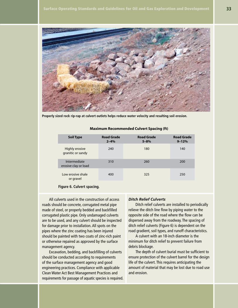
Properly sized rock rip-rap at culvert outlets helps reduce water velocity and resulting soil erosion.
Figure 6. Culvert spacing.
Soil Type Road Grade2–4%
Road Grade5–8%
Maximum Recommended Culvert Spacing (ft)
Road Grade9–12%
Highly erosivegranitic or sandy
Intermediateerosive clay or load
Low erosive shale or gravel
240
310
400
180
260
325
140
200
250
All culverts used in the construction of access roads should be concrete, corrugated metal pipe made of steel, or properly bedded and backfilled corrugated plastic pipe. Only undamaged culverts are to be used, and any culvert should be inspected for damage prior to installation. All spots on the pipes where the zinc coating has been injured should be painted with two coats of zinc-rich paint or otherwise repaired as approved by the surface management agency.
Excavation, bedding, and backfilling of culverts should be conducted according to requirements of the surface management agency and good engineering practices. Compliance with applicable Clean Water Act Best Management Practices and requirements for passage of aquatic species is required.
Ditch Relief Culverts Ditch relief culverts are installed to periodically
relieve the ditch line flow by piping water to the opposite side of the road where the flow can be dispersed away from the roadway. The spacing of ditch relief culverts (Figure 6) is dependent on the road gradient, soil types, and runoff characteristics.
A culvert with an 18-inch diameter is the minimum for ditch relief to prevent failure from debris blockage.
The depth of culvert burial must be sufficient to ensure protection of the culvert barrel for the design life of the culvert. This requires anticipating the amount of material that may be lost due to road use and erosion.

�4
Figure 7. Diagrams for proper culvert installation
Culvert Construction Details
Type 1
Type 2
naturalchannelsurface
In live fish bearing streamslower bottom of culvert 6"below natural channel surface
normal road backslope
elbow
imbedded rocks
minimum 2' or1 1/2 pipe diameters
Do not raise outletabove stream bed
Type 3
Skew Diagram Sidefill
Special Anchoring Type 2 Downdrains
normal road backslope
must dischargeon naturalground
Note:Bedding blanket to be suitablegranular material roughlyshaped to fit bottom of pipe
Note:Minimum cover for pavedsurface is 12" minimumcover for dirt surface is 18"
Provide 3 wraps of#9 galvanized wirearound the pipe andaround each post
2 - 6' metal fence posts
15' maximum
Special archoring to be providedwhen called for in the culvert listing
existing ground
6" compacted layersto density specified
side fill
3D
1 dia.
2D
1/10
dia
.
1 dia. 1 dia.
12' max.12' max.
riprap as required
skew 56˚skew 115˚
115˚
56˚
roadcenterline
minimum 2' or1 1/2 pipe diameters
watercarryingstrata
watercarryingstrata
select backfill
D
B + 1/3 HLine and grade shall be as shown on
plans or as staked on the ground
Place perforations onlower side of pipe
3/4"No. 4No. 16No. 50No. 100
10095–10045–8010–80 2–10
sievedesignation
percentpassing
ground line
select backfill graduation
B = D + 2' – 0"
Type 1
6"
H=
3' –
0"
min
.
B + 1/3 H
12"
6"
H =
3' –
0"
min
.
imperviousmaterial
select backfill
B = D + 2' – 0"
Type 2
D
Perforated Underdrains
in narrow channelsadjust to fit original
stream banks
Suitable granular materials uniformly compacted6"6"
1/2" per foot of fill above top pipe12" minimum 24" maximum
1/10
D
minimum 2' – 0" or 1/3 D
D = pipe diameter or span
minimum 1' – 0" or 1/3 D
slope as staked minimum 1' – 0" or 1/3 D
1' – 0" or 1/3D
minimum 2' – 0" or 1/3 D
naturalground
D D
D
D
2D 2D
Front View Side View
inlet D
outlet 2D
Hand–Laid Rock Headwalls
Rock Foundation
Typical Bedding Details

��Surface Operating Standards and Guidelines for Oil and Gas Exploration and Development
Ditch relief culverts can provide better flow when skewed with an entrance angle of 45 to 60 degrees with the side of the ditch. The culvert gradient should be greater than the approach ditch gradient. This improves the flow hydraulics and reduces siltation and debris plugging the culvert inlet. Culverts placed in natural drainages can also be used for ditch relief.
Bridges and Major CulvertsFederal Highway Administration (FHA)
regulations and BLM and FS road manuals require that on roads open to public travel, all bridges and culverts that in combination span at least 20 feet horizontal distance, must comply with the National Bridge Inspection and Reporting Standards. Thus, BLM and FS manuals require that all such facilities have engineering approval from Regional or State offices. Operators are encouraged to prepare applications requiring major culverts or bridges to allow sufficient time for agency engineering evaluations. Construction of some stream crossings may require a Section 404 Corps of Engineers permit in addition to the approval of the surface management agency.
Wetland CrossingsWetlands are especially sensitive areas and
should be avoided, if possible. Generally, these areas require crossings that prevent unnatural fluctuations in water level. Marshy and swampy terrain may contain bodies of water with no discernible current. The design of culverts for roads crossing these locations requires unique considerations. Construction of some wetland crossings may require a Section 404 Corps of Engineers permit in addition to the approval of the surface management agency.
The culvert should be designed with a flat grade so water can flow either way and maintain its natural water level on both sides. The culvert may become partially blocked by aquatic growth
and should be installed with the flowline below the standing water level at its lowest elevation. Special attention must be given to the selection of culvert materials that will resist corrosion.
Low-Water CrossingsRoads may cross small drainages and
intermittent streams where culverts and bridges are unnecessary. The crossing can be effectively accomplished by dipping the road down to the bed of the drainage. Site-specific designs and the construction of gravel, rip-rap, or concrete bottoms may be required in some situations. In no case should the drainage be filled so that water will be impounded. Low-water crossings that are not surfaced should not be used in wet conditions. Low-water crossings, in combination with culverts, may be utilized if the crossing is designed such that the structure is stable and self cleaning.
SubdrainageIf water is not removed from the subgrade or
pavement structure, it may create instability, reduce load-bearing capacity, increase possible damage from frost action, and create a safety hazard by freezing on the road surface.
Perforated pipe drains and associated filter fabric or aggregate filters may be used when necessary to provide subdrainage. Other methods may be approved by the authorized officer.
Subdrainage systems may effectively reduce final road costs by decreasing the depth of base course needed, thereby reducing subgrade widths. This, in turn, results in less clearing and excavation. Maintenance savings may also be realized as the result of a more stable subgrade.
The solutions to subdrainage problems can be expensive. Road management techniques, such as reducing traffic loads or removing traffic until a subgrade dries out, may be considered as an alternative.

�� Surface Operating Standards and Guidelines for Oil and Gas Exploration and Development
Pipelines and FlowlinesConstruction
Steep hillsides and water courses should be avoided in the location of pipelines and flowlines. Flowline routes should take advantage of road corridors wherever possible to minimize surface disturbance and provide better leak detection and access for installation and repair operations. Consider maintenance needs and safety when burying power and pipelines in or immediately adjacent to the road.
When clearing is necessary, the width disturbed should be kept to a minimum. Topsoil material must be stockpiled to the side of the routes where cuts and fills or other surface disturbances occur during pipeline construction. Topsoil material must be segregated and not be mixed or covered with
subsurface material. Bladed materials must be placed back into the cleared route upon completion of construction and returned back to the original contour before reapplying topsoil.
Pipelines and flowlines should be tested for leaks before backfilling trenches. Pipeline trenches should be compacted during backfilling. After construction, cut-and-fill slopes must be regraded to conform to the adjacent terrain and reclaimed. Pipeline rights-of-way must be maintained in order to correct backfill settling and prevent erosion.
Pipeline construction should not block, dam, or change the natural course of any drainage. Suspended pipelines should provide adequate clearance for high-flow events, floating debris, wildlife, or livestock. Pipelines buried across stream crossings should be buried below the scouring depth.