chapter 3 project description...project description hollister 115 kv power line reconductoring...
TRANSCRIPT
Hollister 115 kV Power Line Reconductoring Project 3-1
November 2009
ICF J&S 00808.07
Chapter 3
Project Description
Project Location
The Hollister 115 kV Power Line Reconductoring Project (proposed project)
includes replacing the conductors (reconductoring) on two segments of the
115 kV electric power line system near Hollister and San Juan Bautista, the
Hollister Tower Segment and the Hollister Pole Segment. An approximately
1.3-mile section of the Hollister Pole Segment will be relocated out of the San
Benito River floodplain (the existing river alignment) to a new river crossing,
with structures located on dry banks above the river (the Proposed River
Crossing).
The Hollister Tower Segment, a 7-mile section of the double-circuit Moss
Landing-Salinas-Soledad 115kV power line, begins at the Lagunitas Switches
near the intersection of Crazy Horse Road and San Juan Grade Road in Monterey
County, and extends northerly to Anzar Junction,1 which is approximately
1.5 miles northwest of the City of San Juan Bautista in San Benito County
(Figure 3-1). The Hollister Tower Segment traverses a series of steep hills with
various vegetative covers, including low-lying grasses, shrubs, and trees.
The Hollister Pole Segment, a 9-mile section of the Hollister No. 1 115 kV power
line that will be rebuilt as a double-circuit line, begins near Anzar Junction, at the
north end of the Hollister Tower Segment, located approximately 1.5 miles
northwest of San Juan Bautista, in San Benito County. The Hollister Pole
Segment extends easterly to the Hollister Substation, located north of the City of
Hollister and approximately 0.25 mile west of San Felipe Road. The Hollister
Pole Segment traverses the San Andreas Rift Zone before entering the San Juan
Valley. The line continues easterly through agricultural fields before crossing the
San Benito River and entering the Flint Hills. The line continues in the Flint
Hills for several miles, then traverses agricultural fields and crosses the Union
Pacific Railroad before reaching the Hollister Substation.
1 The intersection of the Hollister Tower Segment and the Hollister Pole Segment is a point approximately
200 feet from Anzar Junction (a junction in the Watsonville-Salinas 60 kV power line that generally runs
parallel with the Hollister Tower Segment from Lagunitas Switches to Anzar Junction). Because the
intersection between project line segments is close to Anzar Junction and there are no other identifying
features in the immediate area, this document uses Anzar Junction, for ease of reference, to provide a general
dividing point.
Project Description
Hollister 115 kV Power Line Reconductoring Project 3-2
November 2009
ICF J&S 00808.07
For the purposes of this assessment, the project study area is defined as land
within an approximately 500-foot corridor of the existing and proposed project
segments. The project study area is located within unincorporated areas of San
Benito and Monterey Counties and within the sphere of influence of the Cities of
Hollister and San Juan Bautista.
Table 4.9-1 in Section 4.9, Land Use, provides a summary of existing land use,
general plan designations, and zoning designation for each parcel within 500 feet
of the Hollister Substation, Hollister Tower Segment, and Hollister Pole Segment
(including the Proposed River Crossing). Figures 4.9-1 and 4.9-2 illustrate
existing land uses along the project route.
Existing Electric Power System
Both the communities of Hollister and San Juan Bautista are currently served by
the Hollister Substation. In the existing power line system configuration, the
Hollister Substation is supplied by two power lines, the Hollister Nos. 1 and 2
115 kV lines, which begin at the Lagunitas Switches as part of the Moss Landing
– Salinas – Soledad 115kV tower line for approximately 7 miles (the Hollister
Tower Segment) before splitting and extending in different directions to Hollister
Substation. Near Anzar Junction, the Hollister No. 1 pole line (the Hollister Pole
Segment) heads due east to Hollister Substation. The Hollister No. 2 line
continues to the north, then turns east and then south to reach the Hollister
Substation (Figure 3-1). In the event of an outage on either 115 kV line, all of
the Hollister load is served from the remaining line. Figures 3-2 thru 3-19
illustrate the existing system.
The conductors on the Hollister Tower Segment and the Hollister Pole Segment
are comprised of 2/0 and 3/0 copper.
Proposed Project
This project proposes to replace the existing towers with new lattice steel towers
on the Hollister Tower Segment and to replace the existing wood poles on the
Hollister Pole Segment with a combination of tubular steel poles (TSPs) and
light-duty steel (LDS) poles. The existing single-circuit 115 kV power line
within the Hollister Pole Segment will be rebuilt as a double-circuit 115 kV
power line to improve reliability, address current projected growth, and add
needed capacity to the surrounding areas. The Proposed River Crossing will
remove the power line from the San Benito River floodplain (the existing river
alignment).
The preliminary proposed tower and pole locations are illustrated in Figures 3-2
through 3-19. These figures show the preliminary proposed numbers, locations,
and acres of staging areas and pull sites for the Hollister Tower and Hollister
Pole Segments, and existing and proposed access roads. As shown in the figures,
the replacement towers and poles would be within approximately 10 feet of the
Project Description
Hollister 115 kV Power Line Reconductoring Project 3-3
November 2009
ICF J&S 00808.07
existing structures and in the centerline of the right-of-way, except for six towers
that will be placed from 30 to 100 feet from the existing structure.
The Hollister Tower Segment of the proposed project consists of replacing the
conductor and approximately 37 of the 39 towers located in the same alignment
described above. The existing tower segment of the project consists of six
conductors (wires) supported by 39 four-legged, double-circuit towers averaging
82 feet in height. The existing towers are constructed of dull, galvanized, lattice
steel angle members connected by steel bolts. The towers are constructed on
concrete footings. The towers to be removed (refer to ―Tower Removal and
Installation‖) will be replaced with new towers that are similar in size and design.
The Hollister Pole Segment of the project will be reconstructed as a double-
circuit power line in its current alignment, except for the Proposed River
Crossing. The existing pole segment consists of 3/0 and 2/0 copper conductors
supported by approximately 159 wood poles and approximately five LDS poles.
These poles range in height from approximately 60 to 90 feet. Each pole is set
directly into the ground. The replacement LDS poles and TSPs are rusted brown
or ―weathered‖ in appearance. Most of the existing poles will be removed, as
described under ―Pole Removal and Installation.‖
Approximately 17 poles are currently located in the floodplain of the San Benito
River, and approximately 9 additional poles are located in adjacent agricultural
areas. To reduce impacts to the river floodplain area and increase the safety and
reliability of this section due to its location, the Proposed River Crossing will be
relocated approximately 3,000 feet to the north of the existing river alignment
and will span the San Benito River channel from bank to bank above the ordinary
high water mark. To span the river and keep the new power line out of the
floodplain, two engineered (approximately 92-foot) TSPs will be installed above
and back from each bank of the river channel (Figures 3-2 and 3-3).
In addition to the two reconstructed segments, a minor upgrade to the Hollister
Substation will be required. The upgrade includes relocating two existing poles
on the substation property, updating relay settings, and changing the 115 kV bus
conductors.
Project Components
Power Lines
Both circuits of the existing double-circuit 115 kV power line within the Hollister
Tower Segment will be replaced with a 477 kcmil (circular wire gauge size = 1,
000 circular mils) steel-supported aluminum conductor (SSAC) conductor that is
approximately 0.846 inch in diameter. The existing single-circuit 115 kV power
line within the Hollister Pole Segment will be reconstructed as a double-circuit
115 kV power line, also utilizing a 477 kcmil SSAC conductor for each circuit.
The minimum ground to conductor clearance is 30 feet.

Project Description
Hollister 115 kV Power Line Reconductoring Project 3-4
November 2009
ICF J&S 00808.07
Towers/Poles
The Hollister Tower Segment will be constructed with new towers that are
similar in design to the existing towers. The two typical designs for these towers
are shown in Figure 3-20. Approximately 37 towers will be replaced along the
existing alignment, and approximately two towers will be retained. The span
length between towers will range from approximately 51 to 1,847 feet, with an
average span of approximately 850 feet. Each tower is built on four drilled pier
concrete footings. The dimension of each footing is dependent on variables such
as topography, tower height, span length, and soil properties. On average, a
typical footing has an aboveground projection of approximately 3 feet.
The existing lattice steel towers will be dismantled and removed. A crane or
helicopter will be used to take down the tower and remove it from the project
area. Where removal could otherwise cause extensive environmental impacts,
towers will be partially dismantled, with the bases left behind. Tower footings
will be cut down to below ground level or left depending on the environmental
sensitivity of the site.
The Hollister Pole Segment will be reconstructed using a combination of both
TSPs and LDS poles. Approximately 159 existing wood poles will be replaced
with approximately 164 new steel poles. The poles will be rusted brown in
appearance; they range from approximately 70 to 95 feet in height and from
approximately 2 to 6 feet in diameter at the base. The typical design for each
type of pole is shown in Figure 3-21. Span lengths between the poles will range
from approximately 94 to 935 feet, but the average span will be approximately
295 feet. TSPs will be used at angle and dead-end poles where a stronger
structure is needed. This structure is a prefabricated steel top and bottom section.
The bottom section is bolted to a poured-in-place concrete foundation. A heavy
crane is used to install the TSPs, both top and bottom sections. LDS poles can be
installed without the use of a heavy crane.
As noted, approximately17 wood poles are located in the floodplain of the San
Benito River (the existing river alignment) (Figures 3-13 and 3-14). These
existing wood poles in the floodplain will be ―topped‖ (i.e., shortened by
removing the existing power line and cutting down the excess length to the level
of the lower distribution line), allowing the existing distribution line to continue
to serve nearby customers. Approximately four additional wood poles that are
located in the agricultural field west of the river will be topped in a similar
manner. Approximately 10 poles will be removed from this segment as part of
the project. Approximately 22 new steel poles (both TSPs [4] and LDS poles
[18]) will be installed to accommodate the Proposed River Crossing, which is
approximately 3,000 feet north of the existing river alignment.
Pole locations will be sited to minimize impacts to environmentally sensitive
areas. At each pole location, the work area will be flagged by PG&E and/or the
environmental monitor prior to construction. For pole installations near
wetlands, riparian habitat, or special-status plant or wildlife habitat, a biological
monitor (a trained professional biologist) will approve the type and placement of
environmental protections and will monitor the area during construction

Project Description
Hollister 115 kV Power Line Reconductoring Project 3-5
November 2009
ICF J&S 00808.07
activities. Work areas around transmission poles generally will not require
grading or surfacing.
As noted, the average span length for the Hollister Tower Segment is
approximately 850 feet, and the average span length for the Hollister Pole
Segment is approximately 295 feet. No other infrastructure or facilities are co-
located on the Hollister Tower Segment. Approximately 7 miles of one
distribution circuit is co-located (underbuild) on the Hollister Pole Segment. No
other third party facilities are co-located on these power lines.
Substations
A minor upgrade to the Hollister Substation will be required. The upgrade
includes relocating two existing poles on the substation property, updating relay
settings, and changing the 115 kV bus conductors.
Easement Requirements
PG&E currently owns easements along the entire project route except for the
approximately 1.3-mile portion of the Proposed River Crossing. The proposed
realignment will traverse agricultural fields, span the San Benito River, and cross
open grazing lands in the Flint Hills. Relocation of this portion will require
acquisition of easements. For land that PG&E does not own, PG&E will
negotiate easements and other property rights with private landowners for
permanent or temporary use.
Access
Access Roads
Several classes of roads will be used for the project. Road classes, miles, and
acres are listed in Table 3-1 and shown in Figures 3-2 through 3-19.
Approximately 7.94 miles of existing roads will be used for the project that will
not require any substantial upgrades prior to project construction. In addition,
approximately 2.4 miles of existing roads will be upgraded and utilized to access
project features. Approximately 0.39 mile of new permanent access roads will be
constructed as part of the project. Some areas will be accessed over land without
a need for preparation or grooming of a road. Overland travel will occur on
approximately 5.92 mile of gently sloping grassy areas and rangeland; these areas
will not require preparation or surfacing.

Project Description
Hollister 115 kV Power Line Reconductoring Project 3-6
November 2009
ICF J&S 00808.07
Table 3-1. Access Routes
Type of Access
Approximate
Estimated
Miles
Existing dirt and paved roads 9.17
Existing roads to be improved 1.59
New permanent road 0.36
Overland travel 5.92
Total 17.04
Both private and public roads will be accessed. As noted, the Hollister Tower
Segment traverses a series of steep hills with various vegetative covers, including
low-lying grasses, shrubs, and trees. Along this alignment, access via public
roads is limited. One access point to the project area is at the intersection of the
power line and State Route (SR) 156, on the northerly portion of the segment.
Other access points are private dirt roads on large ranch properties adjacent to
San Juan Grade Road.
PG&E has existing rights to private roads located in the existing alignment. If
necessary, PG&E will acquire new rights in portions of the Proposed River
Crossing. PG&E has selected access road routes that minimize environmental
impacts and, where possible, take advantage of existing topography to minimize
the need for grading. Typical access roads will be approximately 15 feet wide,
widening to nearly 30 feet at corners. Most unpaved access roads will not
require surfacing.
Traffic Control
PG&E will implement best management practices (BMPs) regarding traffic.
Encroachment permits will be obtained from the California Department of
Transportation (Caltrans) and San Benito County for crossing jurisdictional
roads, highways, and freeways. If required by Caltrans or San Benito County as
part of the permit, PG&E will prepare a Traffic Control Plan according to the
Caltrans Highway Design Manual requirements.
Traffic control may be required for work along SR 156, San Justo Road, the San
Juan Highway, and local access roadways adjacent to the construction sites.
Occasionally, it may be necessary to temporarily close one lane of traffic.
Appropriate traffic control and safety measures will be implemented, as required
by Caltrans and San Benito County.
Project Description
Hollister 115 kV Power Line Reconductoring Project 3-7
November 2009
ICF J&S 00808.07
Helicopter Access
Helicopters will be used to install towers in locations where overland access is
not possible or access is difficult due to topography and vegetation. Towers 18
and 25 are expected to be installed entirely by helicopter. An excavator is
expected to drive to Towers 17, 19, 20, and 24 to install the foundations; and the
towers are expected to be installed by helicopter. Helicopters will be used to
remove and deliver tower sections, materials, equipment, concrete, and workers
to these tower locations and to other locations where conventional access is
difficult or as otherwise warranted. Preliminary locations for temporary
helicopter landing zones (and staging areas) are shown in Figures 3-2 through
3-19. An area of approximately 200 by 200 feet is required for helicopter
clearance. Helicopters of varying size will use the temporary landing zones to
pick up and drop off crew and materials, and to stage and refuel. These areas
will be sprayed with water as needed for fugitive dust control.
As required by the Federal Aviation Administration (FAA), PG&E will require
the helicopter vendor to develop and implement a Helicopter Lift Plan (see APM
HAZ-3 [Develop and implement a Helicopter Lift Plan] in Section 4.7, ―Hazards
and Hazardous Materials‖).
Vegetation Clearing and Tree Removal
Vegetation Clearing
Vegetation clearing is part of an ongoing annual maintenance activity on the
existing lines, and will not change after project construction. A Consulting
Utility Forester performs an annual inspection of the project facilities. The
inspection takes approximately 2 weeks to complete, and the tree trimming work
generated by the inspection generally is completed within 60–90 days. Weather
can affect the time between inspection and completion of clearing. The area
between the Lagunitas Switches and the Anzar Switch (Hollister Tower
Segment) cannot be worked in during rains, and roads must be allowed drying
time after a rain event. Vegetation clearing in the area between the Anzar Switch
and the Hollister Substation (Hollister Pole Segment) is not similarly restricted
by weather because of the existence of all-season roads. Barring rain, the
average time to complete tree trimming is approximately 30 days.
Tree Removal
Although approximately 136 trees will be removed along the Hollister Tower
Segment, the diameter at breast height (dbh) of the vast majority of these trees is
from 0 to 12 inches. Approximately 85–90 percent of these trees are coastal live
oaks, with approximately 90 percent having a dbh of 0-12 inches. Other trees
include valley oak, oak, bay, and live oak, respectively, in order of their

Project Description
Hollister 115 kV Power Line Reconductoring Project 3-8
November 2009
ICF J&S 00808.07
occurrence. The dbh of approximately 30 trees is 12 to 24 inches, and the dbh of
approximately six trees is within the 24- to 36-inch range.
For the Hollister Pole Segment, three coastal live oaks, one black walnut, and one
fruit tree will be removed in the Anzar Switch area. Aside from trimming, no
other tree work is anticipated along the Hollister Pole Segment. All trees along
Buena Vista Road are across the road and are highly maintained by distribution
inspections (due to the distribution underbuild that is present). The orchards that
parallel the power line, between Poles 20/08 and 21/17, are set back from the line
right-of-way and are trimmed.
PG&E vegetation management policy prohibits removal of trees from riparian
areas without acquiring the appropriate permits. If trimming is required, the trim
is not to exceed 10 percent of the total tree.
Construction Methods
This section describes construction methods to be used for both segments of the
proposed project. It addresses lay down areas and helicopter landing zones
(collectively referred to as staging areas), pull and tension sites (also referred to
as pull sites), access roads, traffic control, helicopter access, tree removal and
vegetation clearing, erosion and sediment control and pollution prevention, and
cleanup and post-construction restoration. The section also discusses
construction methods for power line construction, substation construction, the
construction workforce and equipment, and the construction schedule.
Grading
Grading will be carried out by a contractor with all required environmental
protection in place, and an environmental monitor will be present during grading
activity. If grading takes place near wetlands, riparian habitat, or special-status
plant or wildlife habitat, a biological monitor (a trained professional biologist)
will approve the type and placement of environmental protections and will be
present during these grading activities (see APM 3 [Retain an environmental
monitor onsite during construction activities near sensitive habitat] in
Section 4.4, ―Biological Resources‖).
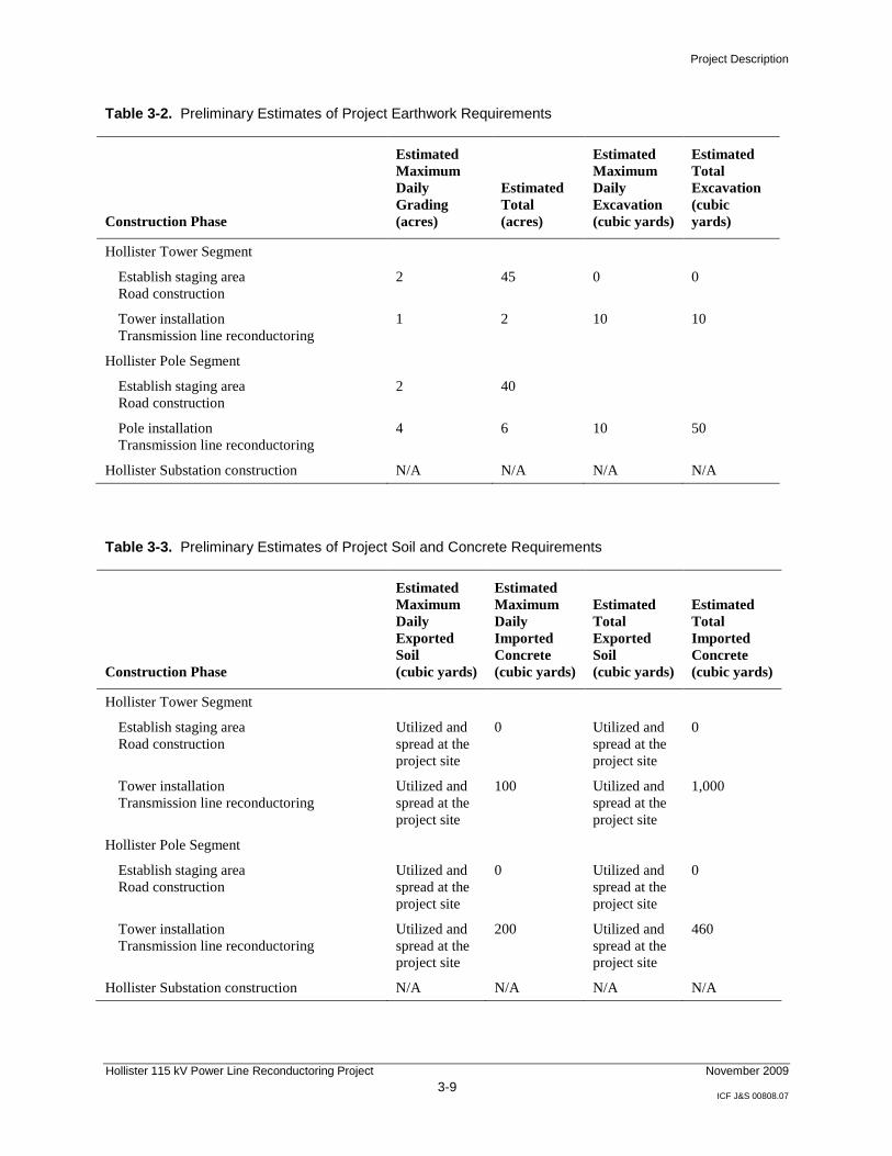
Table 3-2 includes preliminary estimates of project earthwork requirements.
Table 3-3 shows preliminary estimates of project soil and concrete requirements.
Project Description
Hollister 115 kV Power Line Reconductoring Project 3-9
November 2009
ICF J&S 00808.07
Table 3-2. Preliminary Estimates of Project Earthwork Requirements
Construction Phase
Estimated
Maximum
Daily
Grading
(acres)
Estimated
Total
(acres)
Estimated
Maximum
Daily
Excavation
(cubic yards)
Estimated
Total
Excavation
(cubic
yards)
Hollister Tower Segment
Establish staging area
Road construction
2 45 0 0
Tower installation
Transmission line reconductoring
1 2 10 10
Hollister Pole Segment
Establish staging area
Road construction
2 40
Pole installation
Transmission line reconductoring
4 6 10 50
Hollister Substation construction N/A N/A N/A N/A
Table 3-3. Preliminary Estimates of Project Soil and Concrete Requirements
Construction Phase
Estimated
Maximum
Daily
Exported
Soil
(cubic yards)
Estimated
Maximum
Daily
Imported
Concrete
(cubic yards)
Estimated
Total
Exported
Soil
(cubic yards)
Estimated
Total
Imported
Concrete
(cubic yards)
Hollister Tower Segment
Establish staging area
Road construction
Utilized and
spread at the
project site
0 Utilized and
spread at the
project site
0
Tower installation
Transmission line reconductoring
Utilized and
spread at the
project site
100 Utilized and
spread at the
project site
1,000
Hollister Pole Segment
Establish staging area
Road construction
Utilized and
spread at the
project site
0 Utilized and
spread at the
project site
0
Tower installation
Transmission line reconductoring
Utilized and
spread at the
project site
200 Utilized and
spread at the
project site
460
Hollister Substation construction N/A N/A N/A N/A

Project Description
Hollister 115 kV Power Line Reconductoring Project 3-10
November 2009
ICF J&S 00808.07
Erosion and Sediment Control and Pollution Prevention during Construction
PG&E will prepare a Storm Water Pollution Prevention Plan (SWPPP) for the
entire project, and workers will receive written and tailboard instructions on the
plan (see APM HYDRO-1 [Prepare and implement a Storm Water Pollution
Prevention Plan] in Section 4.8, ―Hydrology and Water Quality‖).
Implementation of the SWPPP will prevent construction-related erosion and
sediments from entering nearby waterways. As part of the SWPPP, PG&E will
develop and implement a Spill Prevention Control and Countermeasure Plan
(SPCCP) (see APM HYDRO-2 [Develop and implement a Spill Prevention
Control and Countermeasure Plan] in Section 4.8, ―Hydrology and Water
Quality‖). The SPCCP will be completed and included in the SWPPP before any
construction activities begin. PG&E will routinely inspect the construction areas
to verify that the control measures specified in the SWPPP are properly
implemented and maintained.
Construction of Hollister Tower and Pole Segments
Staging Areas and Pull Sites
Prior to project construction, staging areas and pull sites will be established along
the alignment. Along the Hollister Tower Segment, approximately five staging
areas and approximately seven pull sites will be established. For the Hollister
Pole Segment, approximately six staging areas and approximately 12 pull sites
will be established.
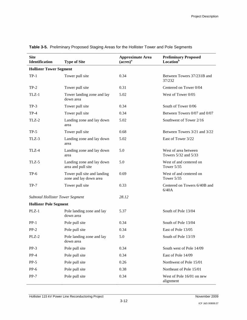
Table 3-4 provides the estimated acreages of disturbance from project-related
activities. Table 3-5 identifies the preliminary proposed numbers, locations, and
acres of staging areas and pull sites for the Hollister Tower and Hollister Pole
Segments. These areas are illustrated in Figures 3-2 through 3-19.

Project Description
Hollister 115 kV Power Line Reconductoring Project 3-11
November 2009
ICF J&S 00808.07
Table 3-4. Estimates of Approximate Temporary and Permanent Disturbance
Project Activity
Approximate
Temporary
Disturbancea
(acres)
Approximate
Permanent
Disturbanceb
(acres)
Replacing towers and poles
Hollister Tower Segment (37 towers) 1.84 0.33
Hollister Pole Segment (142 poles) 5.84 0.11
Subtotal towers and poles 7.68 0.44
Construction areas (includes lay down [staging] areas, pull sites, and helicopter landing
zones, tower removal work areas and work area overland travel route)
Hollister Tower Segment 35.42 5.1
Hollister Pole Segment 36.6 0.0
Subtotal construction areas 72.02 5.1
Access roads 3.76 4.28
Project total 83.46 9.82
Note: Estimated disturbance acreages are based on the following assumptions: temporary disturbance for
the Hollister Tower Segment is 2,500 square feet per tower, and permanent disturbance is 400 square feet
per tower. Temporary disturbance for the Hollister Pole Segment is 1,600 square feet, and permanent
disturbance is 30 square feet per pole. Because the majority of towers and poles already exist and are
being replaced in kind, the only new permanent disturbance is associated with the Proposed River
Crossing.
a Temporary disturbance represents construction activities associated with installation and removal of
towers and poles. b Permanent disturbance represents the overall footprint area under each tower; limited access remains
under each tower (e.g., for cattle grazing). c Table 3-5 contains the details of the acreage to be temporarily disturbed by construction areas. d Table 3-1 shows preliminary estimates of access routes.
Project Description
Hollister 115 kV Power Line Reconductoring Project 3-12
November 2009
ICF J&S 00808.07
Table 3-5. Preliminary Proposed Staging Areas for the Hollister Tower and Pole Segments
Site
Identification Type of Site
Approximate Area
(acres)a
Preliminary Proposed
Locationb
Hollister Tower Segment
TP-1 Tower pull site 0.34 Between Towers 37/231B and
37/232
TP-2 Tower pull site 0.31 Centered on Tower 0/04
TLZ-1 Tower landing zone and lay
down area
5.02 West of Tower 0/05
TP-3 Tower pull site 0.34 South of Tower 0/06
TP-4 Tower pull site 0.34 Between Towers 0/07 and 0/07
TLZ-2 Landing zone and lay down
area
5.02 Southwest of Tower 2/16
TP-5 Tower pull site 0.68 Between Towers 3/21 and 3/22
TLZ-3 Landing zone and lay down
area
5.02 East of Tower 3/22
TLZ-4 Landing zone and lay down
area
5.0 West of area between
Towers 5/32 and 5/33
TLZ-5 Landing zone and lay down
area and pull site
5.0 West of and centered on
Tower 5/35
TP-6 Tower pull site and landing
zone and lay down area
0.69 West of and centered on
Tower 5/35
TP-7 Tower pull site 0.33 Centered on Towers 6/40B and
6/40A
Subtotal Hollister Tower Segment 28.12
Hollister Pole Segment
PLZ-1 Pole landing zone and lay
down area
5.37 South of Pole 13/04
PP-1 Pole pull site 0.34 South of Pole 13/04
PP-2 Pole pull site 0.34 East of Pole 13/05
PLZ-2 Pole landing zone and lay
down area
5.0 South of Pole 13/19
PP-3 Pole pull site 0.34 South west of Pole 14/09
PP-4 Pole pull site 0.34 East of Pole 14/09
PP-5 Pole pull site 0.26 Northwest of Pole 15/01
PP-6 Pole pull site 0.38 Northeast of Pole 15/01
PP-7 Pole pull site 0.34 West of Pole 16/01 on new
alignment
Project Description
Hollister 115 kV Power Line Reconductoring Project 3-13
November 2009
ICF J&S 00808.07
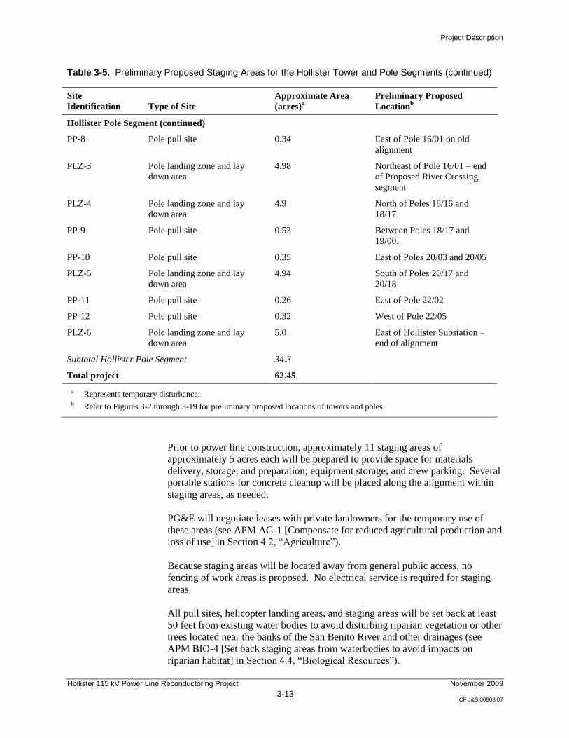
Table 3-5. Preliminary Proposed Staging Areas for the Hollister Tower and Pole Segments (continued)
Site
Identification Type of Site
Approximate Area
(acres)a
Preliminary Proposed
Locationb
Hollister Pole Segment (continued)
PP-8 Pole pull site 0.34 East of Pole 16/01 on old
alignment
PLZ-3 Pole landing zone and lay
down area
4.98 Northeast of Pole 16/01 – end
of Proposed River Crossing
segment
PLZ-4 Pole landing zone and lay
down area
4.9 North of Poles 18/16 and
18/17
PP-9 Pole pull site 0.53 Between Poles 18/17 and
19/00.
PP-10 Pole pull site 0.35 East of Poles 20/03 and 20/05
PLZ-5 Pole landing zone and lay
down area
4.94 South of Poles 20/17 and
20/18
PP-11 Pole pull site 0.26 East of Pole 22/02
PP-12 Pole pull site 0.32 West of Pole 22/05
PLZ-6 Pole landing zone and lay
down area
5.0 East of Hollister Substation –
end of alignment
Subtotal Hollister Pole Segment 34.3
Total project 62.45
a Represents temporary disturbance. b Refer to Figures 3-2 through 3-19 for preliminary proposed locations of towers and poles.
Prior to power line construction, approximately 11 staging areas of
approximately 5 acres each will be prepared to provide space for materials
delivery, storage, and preparation; equipment storage; and crew parking. Several
portable stations for concrete cleanup will be placed along the alignment within
staging areas, as needed.
PG&E will negotiate leases with private landowners for the temporary use of
these areas (see APM AG-1 [Compensate for reduced agricultural production and
loss of use] in Section 4.2, ―Agriculture‖).
Because staging areas will be located away from general public access, no
fencing of work areas is proposed. No electrical service is required for staging
areas.
All pull sites, helicopter landing areas, and staging areas will be set back at least
50 feet from existing water bodies to avoid disturbing riparian vegetation or other
trees located near the banks of the San Benito River and other drainages (see
APM BIO-4 [Set back staging areas from waterbodies to avoid impacts on
riparian habitat] in Section 4.4, ―Biological Resources‖).
Project Description
Hollister 115 kV Power Line Reconductoring Project 3-14
November 2009
ICF J&S 00808.07
Construction of Power Line
Construction of the project will include installation of lattice steel towers, TSPs,
and LDS poles; installation of temporary wood poles; removal of the existing
wood poles and conductor; topping of some existing wood poles;
installation/removal of safety structures at road crossings; and stringing new
conductor for the 115 kV circuits. The existing 115 kV conductor will be
removed and replaced with a 477 kcmil SSAC conductor. In addition, the
Proposed River Crossing will require acquisition and preparation of easements
and establishment of staging areas and pull sites prior to construction.
Pull and Tension Sites
To replace or install a length of conductor, a pull site is needed at one end and a
tension site is needed at the other; pull and tension sites are temporary. They
vary in size depending on the existing terrain for the activity and whether the site
will be a pull or a tension site; typically, an approximately 100- by 300-foot area
is adequate. Pull sites require a puller, crew truck, and aerial lift truck; tension
sites require a tensioner, crew truck, reel dolly, aerial lift, and truck to move the
reel dolly. The old conductor will be removed and placed on a collapsible reel.
The reel will be transported from the site on a flatbed truck to an authorized
recovery facility.
Tower Removal and Installation
The construction process will begin by removing the old conductor. Then the
towers will be dismantled. Project construction will involve removal of
approximately 37 existing towers and installation of approximately 37 new
towers, as shown in Table 3-6.
The tops of the exposed foundations will be broken up and removed. Old
foundation holes will be filled with existing soil excavated from the new tower
foundations.
New foundation footings will be augured in place. New rebar cages will be
placed in the newly drilled hole, and concrete will be poured at foundation
locations. The new towers then will be erected and bolted together.
Once all new towers have been constructed, the line insulators will be installed
on each tower. Then the rollers will be connected, and sock line will be flown in
via helicopter. Once this assembly is completed, the new conductor will be
pulled.
Project Description
Hollister 115 kV Power Line Reconductoring Project 3-15
November 2009
ICF J&S 00808.07
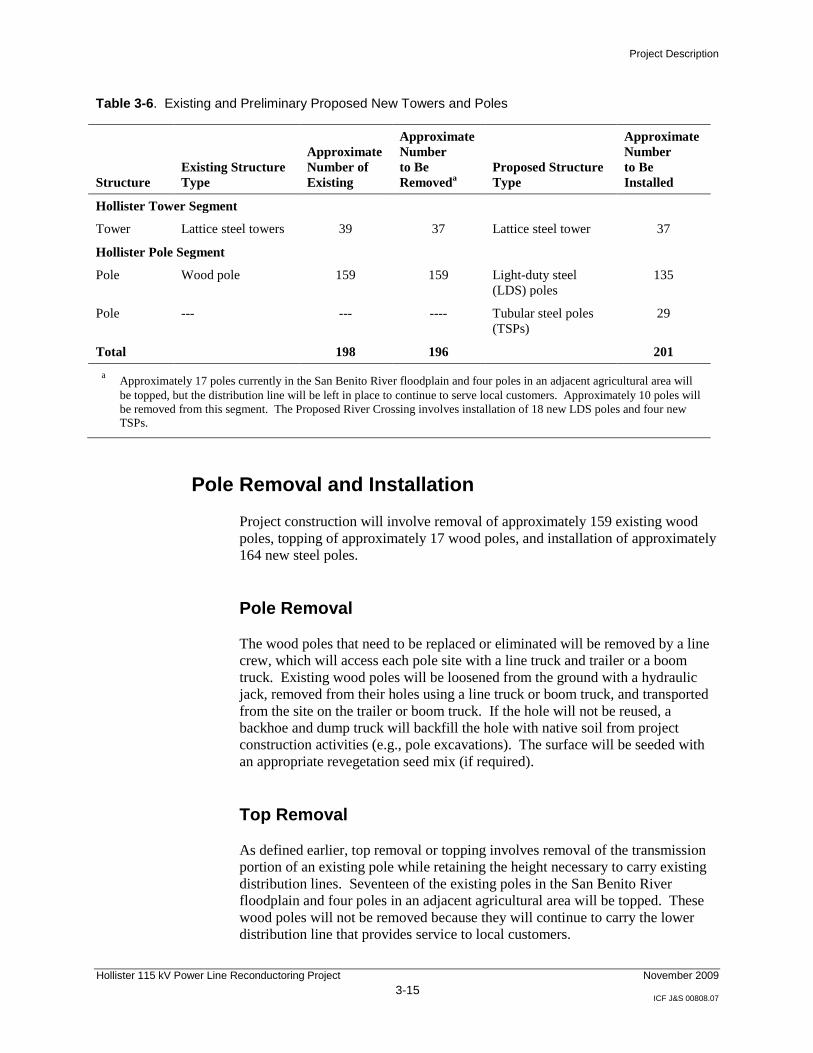
Table 3-6. Existing and Preliminary Proposed New Towers and Poles
Structure
Existing Structure
Type
Approximate
Number of
Existing
Approximate
Number
to Be
Removeda
Proposed Structure
Type
Approximate
Number
to Be
Installed
Hollister Tower Segment
Tower Lattice steel towers 39 37 Lattice steel tower 37
Hollister Pole Segment
Pole Wood pole 159 159 Light-duty steel
(LDS) poles
135
Pole --- --- ---- Tubular steel poles
(TSPs)
29
Total 198 196 201
a Approximately 17 poles currently in the San Benito River floodplain and four poles in an adjacent agricultural area will
be topped, but the distribution line will be left in place to continue to serve local customers. Approximately 10 poles will
be removed from this segment. The Proposed River Crossing involves installation of 18 new LDS poles and four new
TSPs.
Pole Removal and Installation
Project construction will involve removal of approximately 159 existing wood
poles, topping of approximately 17 wood poles, and installation of approximately
164 new steel poles.
Pole Removal
The wood poles that need to be replaced or eliminated will be removed by a line
crew, which will access each pole site with a line truck and trailer or a boom
truck. Existing wood poles will be loosened from the ground with a hydraulic
jack, removed from their holes using a line truck or boom truck, and transported
from the site on the trailer or boom truck. If the hole will not be reused, a
backhoe and dump truck will backfill the hole with native soil from project
construction activities (e.g., pole excavations). The surface will be seeded with
an appropriate revegetation seed mix (if required).
Top Removal
As defined earlier, top removal or topping involves removal of the transmission
portion of an existing pole while retaining the height necessary to carry existing
distribution lines. Seventeen of the existing poles in the San Benito River
floodplain and four poles in an adjacent agricultural area will be topped. These
wood poles will not be removed because they will continue to carry the lower
distribution line that provides service to local customers.
Project Description
Hollister 115 kV Power Line Reconductoring Project 3-16
November 2009
ICF J&S 00808.07
Poles to be topped will be accessed by a pole crew on foot and, where feasible,
by a line truck and trailer or a boom truck. The walk-in crew will climb the pole
and cut off the top. The top then will be removed, either by hand or by
helicopter. If use of a line truck or boom truck is feasible, the truck will be used
to hold the top of the pole in place, a chainsaw will be used to cut the pole, and
the top section will be removed and disposed of.
Pole Installation
Installation of TSPs involves these steps: staking the pole location; flagging the
work area; installing silt fencing (if required); preparing the crane pad (if
required); excavating the hole; installing forms, rebar, and anchor bolts; pouring
concrete; removing forms; placing gravel around and grooming the base area;
installing the new pole; removing the old conductor and stringing the new
conductor; removing the old wood pole; and spreading the excess soil onsite and
trucking other construction materials offsite for disposal.
Installation of wood poles and LDS poles involves these steps: staking the pole
location, flagging the work area, implementing BMPs if required, excavating,
installing the pole, backfilling, transferring wire and equipment, removing the old
conductor and stringing the new conductor, removing the old pole, and
backfilling.
PG&E will temporarily install approximately two wood poles (shoe-flys) at each
angle of the existing Hollister Pole Segment to accommodate replacement of the
existing wood pole with a new TSP.
While the Hollister Tower Segment and the Hollister Pole Segment are being
constructed, the existing Watsonville–Salinas 60 kV power line, which parallels
the Hollister Tower Segment northerly to the Hollister Pole Segment, will be
temporarily upgraded to 115 kV and serve as the 115 kV feed to the Hollister
Substation. To connect the Watsonville–Salinas 60 kV power line to the 115 kV
system, PG&E will temporarily install three wood poles at the southerly end and
one wood pole at the northerly end of the Hollister Tower Segment.
Pole locations will be sited to both maximize spans and avoid environmentally
sensitive areas. At each pole location, the work area will be flagged by PG&E
and the environmental monitor prior to construction. For pole installations near
wetlands, riparian habitat, or special-status plant or wildlife habitat, a biological
monitor (a trained professional biologist) will approve the type and placement of
environmental protections and will monitor the area during construction activities
(see APM BIO-3 in Section 4.4, ―Biological Resources‖).
An approximately 50-foot radius around each pole will be required for a work
area. Some work areas may require removal of vegetation and installation of silt
fencing (e.g., during the wet season, if required). Work areas around poles
generally will not require grading or surfacing. The approximately 16 pull sites
will require preparation. Temporary crane pads will need to be built if the terrain
Project Description
Hollister 115 kV Power Line Reconductoring Project 3-17
November 2009
ICF J&S 00808.07
will not allow for safe operation of a crane. The size of the pad will vary based
on the terrain.
LDS poles supporting straight spans are set directly into the soil. LDS poles may
be set to a depth of approximately 7 to 12 feet below grade.
All angle poles are TSPs, which eliminate the need for wire down guys. All
TSPs will have concrete pier foundations that are approximately 5 to 7 feet in
diameter and from approximately 15 to 30 feet deep. The use of TSPs eliminates
visual clutter at the structure locations, decreases the damage potential to the pole
by eliminating the opportunity for contacts with the guys during agricultural and
farming operations, and decreases the potential for bird strikes.
Drilling and excavation of holes for temporary wood poles, LDS poles, and TSPs
will use a hole auger, backhoe, dump truck, and crew truck—all of which will
access pole locations via existing paved and dirt roads where available and over
land where roads do not exist. A hole auger consists of an auger mounted on a
heavy truck chassis or piece of track equipment that will be used to drill holes.
A boom truck consisting of a small crane mounted on a flatbed truck will be used
to haul foundation forms, anchor bolts, rebar, and pole structures to the TSP
locations. The boom truck also will be used to place foundation forms, anchor
bolts, and rebar in place prior to pouring of concrete for the foundation—and to
remove the forms following completion of the foundation.
A concrete truck consisting of a four-wheel drive mixer capable of delivering
8 yards of concrete will be used to deliver and pour concrete for the TSP
foundations. Concrete trucks will not be washed out at pole locations; cleaning
pits will be established at staging areas throughout the project area to minimize
time between the concrete pour and truck cleanout. All cleaning pit locations
will be approved by an environmental monitor. These pits will include dike
walls and tarping, which will allow washed materials to be properly contained
and disposed of. A backhoe will be used to place gravel around the TSP
foundation after formwork has been removed and to groom the area immediately
surrounding all pole installations.
A crane will be used to place TSPs on the foundations. The line truck will be
used to place the LDS and temporary wood poles in the excavated hole and to
remove the old wood pole. Aerial lift trucks will be used to install, transfer, and
remove conductors. Crew trucks will be used to transport the crew, their hand
tools, and other minor materials to and from pole locations. Crew trucks will be
used to minimize the number of vehicles accessing each site and to reduce
vehicle-related impacts.
Helicopter Installation
Installation of some poles or towers may require the use of a helicopter and
special construction techniques. Typically, an excavator will be used to auger the
foundations; in cases where an excavator cannot access the site, a crew will walk
Project Description
Hollister 115 kV Power Line Reconductoring Project 3-18
November 2009
ICF J&S 00808.07
in the auger. Excavated soils, foundation forms, concrete, TSPs, and
miscellaneous tools and materials will be transported in or out by helicopter, as
required. The crews may drive on existing roads to a nearby location, park, and
walk the remainder of the way to some sites. Helicopters may transport some
construction workers to remote sites.
Conductor/Cable Installation
All of the old conductors (power line wires) will be removed, and new
conductors will be installed. Prior to stringing conductors, temporary clearance
structures will be installed at road crossings and other locations where the new
conductors could otherwise come into contact with electrical or communication
facilities, other power lines, or vehicular traffic during installation. The
temporary structures will be installed across SR 156, San Juan Highway, San
Justo Road, and the Union Pacific Railroad crossing.
The temporary structures consist of a wood pole with a frame at the top that
resembles a ―Y‖ or ―H‖ that are placed on each side of the road or power line
being crossed. Foundations and grading are not required. Methods for
installation and removal of clearance structures are similar to those described for
wood poles. As noted, these structures prevent the conductor from being lowered
or falling into traffic or onto another power line. Netting is installed between the
two Y-frame structures as needed to avoid contact between the new conductor
and an existing facility.
Traffic control will be provided where necessary during installation and removal
of these temporary clearance structures, and as specified in Caltrans and San
Benito County encroachment permits.
Replacement of Existing Conductor
To replace an existing conductor with a new conductor, the existing conductor
will first be detached from its support structure and temporarily lifted. Rollers
then will be installed at the conductor’s attachment point, and the conductor will
be placed onto the rollers. Installation of rollers and detachment of the existing
conductor will require one aerial lift of the conductors by either a boom truck or
a helicopter.
Once rollers are in place for the entire section of conductor being replaced, the
existing conductor will be pulled out of place. A pulling (sock) line will be
attached to the existing conductor, which then will be used to pull the new
conductor into place. Removal of the existing conductor and installation of the
new conductor will require establishment of pull and tension sites. Equipment at
the pull sites will pull the conductor onto a reel, where it will be collected for
salvage. Equipment at the tension site will feed new conductor along the rollers
previously installed at each structure while maintaining tension in the line so that
it does not sag to the ground. Once the new conductor is in place, the rollers will
be removed, and the new conductor will be attached to the structures.
Project Description
Hollister 115 kV Power Line Reconductoring Project 3-19
November 2009
ICF J&S 00808.07
Installation of New Conductor
Prior to the installation of a new conductor, rollers will be installed at vacant
positions on new structures using one helicopter lift. The helicopter then will be
used to install a pulling (sock) line in the rollers. Once installed, the sock line
will be used to pull the new conductor into place. When the conductor has been
pulled through the rollers, an aerial lift typically is used to remove the rollers and
attach the conductor to the structures.
Construction of Substation
Modifications at the Hollister Substation will be performed completely on PG&E
property. Materials and equipment will be stored on PG&E property. Each
substation work crew will use a crew truck that will be located within the existing
substation yard.
Cleanup and Post-Construction Restoration
Crews will be required to maintain clean work areas as they proceed along the
line, and they will be instructed that no debris may be left behind at any stage of
the project. The cleanup and restoration process will include reseeding disturbed
areas as specified in the SWPPP, primarily at crane pad locations. In some cases,
as specified in leases with property owners, the land may be left alone for nature
to take its course.
Project-generated refuse, spoil, and trash will kept onsite with compliant
containers and disposal processes or transported to the nearest service center. Oil
and treated wood project storage onsite require site secondary containment,
managed storage, and labeling with manifested disposal/recycling processing.
Insulators will be stored separately and recovered. Steel, wire, and hardware
[requires set-up project recovery processes] please re-phrase in English – will be
recycled? Sorted and disposed of somewhere?].
Upon completion of the project, the areas will be left as specified in the
individual lease agreements. The site layouts will be approved by the project’s
environmental monitor, and work crew activities will follow all PG&E
environmental guidelines.
Construction Workforce and Equipment
Project construction will require an excavation crew, light-duty helicopter crew,
heavy-duty helicopter crew, pole crew, line crew, substation crew, and
environmental monitor. Table 3-7 describes the role of each crew.
Project Description
Hollister 115 kV Power Line Reconductoring Project 3-20
November 2009
ICF J&S 00808.07
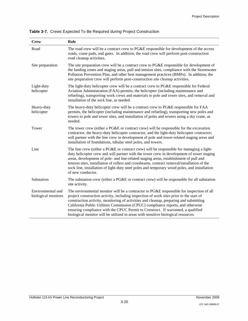
Table 3-7. Crews Expected To Be Required during Project Construction
Crew Role
Road The road crew will be a contract crew to PG&E responsible for development of the access
roads, crane pads, and gates. In addition, the road crew will perform post-construction
road cleanup activities.
Site preparation The site preparation crew will be a contract crew to PG&E responsible for development of
the landing zones and staging areas, pull and tension sites, compliance with the Stormwater
Pollution Prevention Plan, and other best management practices (BMPs). In addition, the
site preparation crew will perform post-construction site cleanup activities.
Light-duty
helicopter
The light-duty helicopter crew will be a contract crew to PG&E responsible for Federal
Aviation Administration (FAA) permits, the helicopter (including maintenance and
refueling), transporting work crews and materials to pole and tower sites, and removal and
installation of the sock line, as needed.
Heavy-duty
helicopter
The heavy-duty helicopter crew will be a contract crew to PG&E responsible for FAA
permits, the helicopter (including maintenance and refueling), transporting new poles and
towers to pole and tower sites, and installation of poles and towers using a sky crane, as
needed.
Tower The tower crew (either a PG&E or contract crew) will be responsible for the excavation
contractor, the heavy-duty helicopter contractor, and the light-duty helicopter contractor;
will partner with the line crew in development of pole and tower-related staging areas and
installation of foundations, tubular steel poles, and towers.
Line The line crew (either a PG&E or contract crew) will be responsible for managing a light-
duty helicopter crew and will partner with the tower crew in development of tower staging
areas, development of pole- and line-related staging areas, establishment of pull and
tension sites, installation of rollers and crossbeams, contract removal/installation of the
sock line, installation of light-duty steel poles and temporary wood poles, and installation
of new conductor.
Substation The substation crew (either a PG&E or contract crew) will be responsible for all substation
site activity.
Environmental and
biological monitors
The environmental monitor will be a contractor to PG&E responsible for inspection of all
project construction activity, including inspection of work sites prior to the start of
construction activity, monitoring of activities and cleanup, preparing and submitting
California Public Utilities Commission (CPUC) compliance reports, and otherwise
ensuring compliance with the CPUC Permit to Construct. If warranted, a qualified
biological monitor will be utilized in areas with sensitive biological resources.
Project Description
Hollister 115 kV Power Line Reconductoring Project 3-21
November 2009
ICF J&S 00808.07
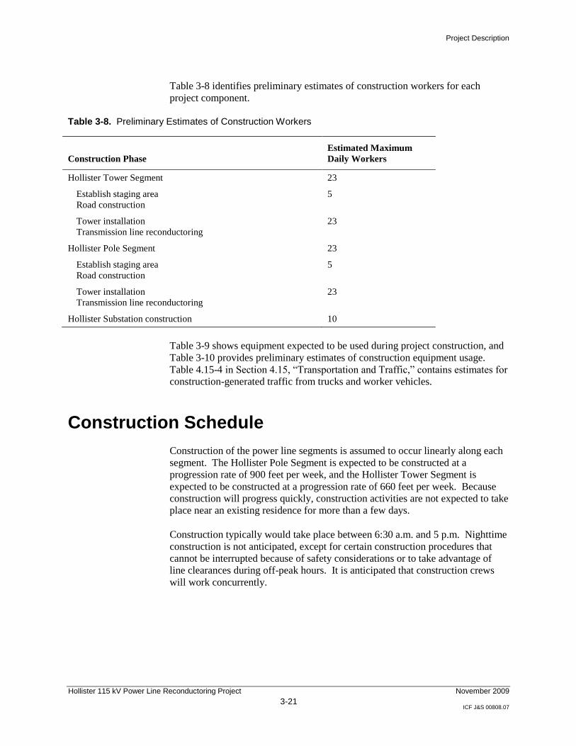
Table 3-8 identifies preliminary estimates of construction workers for each
project component.
Table 3-8. Preliminary Estimates of Construction Workers
Construction Phase
Estimated Maximum
Daily Workers
Hollister Tower Segment 23
Establish staging area
Road construction
5
Tower installation
Transmission line reconductoring
23
Hollister Pole Segment 23
Establish staging area
Road construction
5
Tower installation
Transmission line reconductoring
23
Hollister Substation construction 10
Table 3-9 shows equipment expected to be used during project construction, and
Table 3-10 provides preliminary estimates of construction equipment usage.
Table 4.15-4 in Section 4.15, ―Transportation and Traffic,‖ contains estimates for
construction-generated traffic from trucks and worker vehicles.
Construction Schedule
Construction of the power line segments is assumed to occur linearly along each
segment. The Hollister Pole Segment is expected to be constructed at a
progression rate of 900 feet per week, and the Hollister Tower Segment is
expected to be constructed at a progression rate of 660 feet per week. Because
construction will progress quickly, construction activities are not expected to take
place near an existing residence for more than a few days.
Construction typically would take place between 6:30 a.m. and 5 p.m. Nighttime
construction is not anticipated, except for certain construction procedures that
cannot be interrupted because of safety considerations or to take advantage of
line clearances during off-peak hours. It is anticipated that construction crews
will work concurrently.

Project Description
Hollister 115 kV Power Line Reconductoring Project 3-22
November 2009
ICF J&S 00808.07
Table 3-9. Equipment Expected To Be Used during Project Construction
Type of Equipment Use
Aerial lifts
Backhoe
Boom truck
Low Drill
Concrete mixer truck
Crane
Crew-cab truck/pick-ups
Dump truck
Equipment/tool vans
Grooming/grading equipment:
Dozer
Water truck
Grader
Rock transport
Roller
Helicopters (light and heavy duty)
Hole auger
Hydraulic jack
Line truck and trailer
Materials storage units
Mobile offices
Puller
Reel dolly
Tensioner
Remove old conductor and install new
Excavate foundations, spoil removal, backfill
Erect structures
Erect structures
Haul concrete
Erect structures
Transport personnel, tools, and materials
Haul material
Tool storage and transportation
Road construction and crane pads:
Move/compact soils
Compact soils and control dust
Properly pitch road for run-off
Deliver road base for access roads, staging areas,
and pull sites
Compact road and surfaces
Erect poles and towers, install sock line, haul
materials, equipment, and people
Excavate holes
Remove wood poles
Haul conductor, poles, equipment, materials, and
people, and to install pole/conductor
Store material/tools
Supervision and clerical office
Install conductor
Install and move conductor
Install conductor
Project Description
Hollister 115 kV Power Line Reconductoring Project 3-23
November 2009
ICF J&S 00808.07
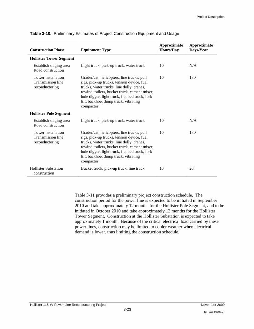
Table 3-10. Preliminary Estimates of Project Construction Equipment and Usage
Construction Phase Equipment Type
Approximate
Hours/Day
Approximate
Days/Year
Hollister Tower Segment
Establish staging area
Road construction
Light truck, pick-up truck, water truck 10 N/A
Tower installation
Transmission line
reconductoring
Grader/cat, helicopters, line trucks, pull
rigs, pick-up trucks, tension device, fuel
trucks, water trucks, line dolly, cranes,
rewind trailers, bucket truck, cement mixer,
hole digger, light truck, flat bed truck, fork
lift, backhoe, dump truck, vibrating
compactor.
10 180
Hollister Pole Segment
Establish staging area
Road construction
Light truck, pick-up truck, water truck 10 N/A
Tower installation
Transmission line
reconductoring
Grader/cat, helicopters, line trucks, pull
rigs, pick-up trucks, tension device, fuel
trucks, water trucks, line dolly, cranes,
rewind trailers, bucket truck, cement mixer,
hole digger, light truck, flat bed truck, fork
lift, backhoe, dump truck, vibrating
compactor
10 180
Hollister Substation
construction
Bucket truck, pick-up truck, line truck 10 20
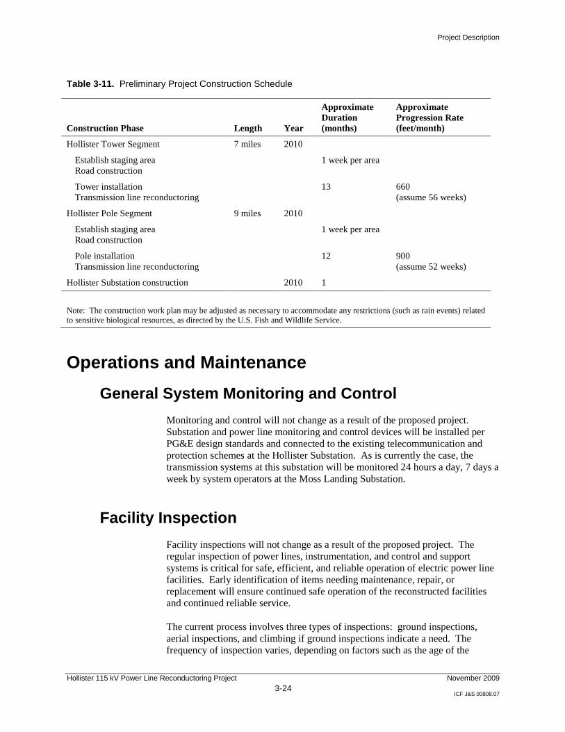
Table 3-11 provides a preliminary project construction schedule. The
construction period for the power line is expected to be initiated in September
2010 and take approximately 12 months for the Hollister Pole Segment, and to be
initiated in October 2010 and take approximately 13 months for the Hollister
Tower Segment. Construction at the Hollister Substation is expected to take
approximately 1 month. Because of the critical electrical load carried by these
power lines, construction may be limited to cooler weather when electrical
demand is lower, thus limiting the construction schedule.
Project Description
Hollister 115 kV Power Line Reconductoring Project 3-24
November 2009
ICF J&S 00808.07
Table 3-11. Preliminary Project Construction Schedule
Construction Phase Length Year
Approximate
Duration
(months)
Approximate
Progression Rate
(feet/month)
Hollister Tower Segment 7 miles 2010
Establish staging area
Road construction
1 week per area
Tower installation
Transmission line reconductoring
13 660
(assume 56 weeks)
Hollister Pole Segment 9 miles 2010
Establish staging area
Road construction
1 week per area
Pole installation
Transmission line reconductoring
12 900
(assume 52 weeks)
Hollister Substation construction 2010 1
Note: The construction work plan may be adjusted as necessary to accommodate any restrictions (such as rain events) related
to sensitive biological resources, as directed by the U.S. Fish and Wildlife Service.
Operations and Maintenance
General System Monitoring and Control
Monitoring and control will not change as a result of the proposed project.
Substation and power line monitoring and control devices will be installed per
PG&E design standards and connected to the existing telecommunication and
protection schemes at the Hollister Substation. As is currently the case, the
transmission systems at this substation will be monitored 24 hours a day, 7 days a
week by system operators at the Moss Landing Substation.
Facility Inspection
Facility inspections will not change as a result of the proposed project. The
regular inspection of power lines, instrumentation, and control and support
systems is critical for safe, efficient, and reliable operation of electric power line
facilities. Early identification of items needing maintenance, repair, or
replacement will ensure continued safe operation of the reconstructed facilities
and continued reliable service.
The current process involves three types of inspections: ground inspections,
aerial inspections, and climbing if ground inspections indicate a need. The
frequency of inspection varies, depending on factors such as the age of the
Project Description
Hollister 115 kV Power Line Reconductoring Project 3-25
November 2009
ICF J&S 00808.07
system, structure type, vegetation conditions, and other factors. For the proposed
project power lines, it is generally assumed that PG&E ―maintenance
troublemen‖ will inspect all structures from the ground annually for corrosion,
misalignment, deterioration, and foundation failures. In addition, ground
inspection will occur on selected lines to check the condition of hardware,
insulators, and conductors. Inspection will include checking conductors and
fixtures for corrosion, breaks, broken insulators, and failing splices.
PG&E will conduct inspections by driving to the poles in a pick-up truck where
feasible. Maintenance troublemen will use an all-terrain vehicle or go by foot
where needed to minimize surface disturbance and in certain areas where access
is difficult. Aerial inspection using helicopters may be conducted if needed.
Any specific access requirements that may result from right-of-way negotiations
with property owners will be documented and provided to the maintenance
troublemen, with instructions to comply with these access requirements during
inspection and maintenance. For more detail, please refer to the Overhead Line
Inspection Guideline (PG&E 1998).
Maintenance Procedures
Maintenance procedures will not change as a result of the proposed project.
Maintenance of the power line is generally on an as-needed basis, when the
troublemen discover something needing repair or in response to an emergency.
A benefit of using mostly lattice steel towers, TSPs, and LDS poles for this
project is that they generally require less maintenance than wood poles.
Consistent with current practice, the PG&E vegetation management inspector
will inspect and document vegetation conditions annually. Where needed,
vegetation inspections may be conducted more frequently. To maintain
appropriate clearance under the power line, vegetation removal will be performed
on an annual basis or as needed.
Equipment modifications at the Hollister Substation are not expected to change
existing maintenance procedures. Maintenance on the equipment is performed as
needed. Because the power line and substation modifications are not expected to
require additional employees for operation and maintenance, the project will not
generate additional traffic.
Applicant-Proposed Measures
Applicant-proposed measures (APMs) have been incorporated into the project
design that will be implemented to avoid or minimize impacts. These APMs are
included in the respective resource section. A complete list of APMs is found in
Chapter 5, ―Applicant’s Proposed Measures.‖
Implementation of the proposed APMs will ensure that all potential project-
related impacts will be avoided or less than significant.
Project Description
Hollister 115 kV Power Line Reconductoring Project 3-26
November 2009
ICF J&S 00808.07
Electric and Magnetic Fields Summary
Recognizing that there is public interest and concern regarding potential health
effects from exposure to electric and magnetic fields (EMF) from power line
lines, this document provides some general background information regarding
EMF associated with electric utility facilities in Appendix E. However, EMF is
not addressed here as an environmental impact under CEQA. The CPUC has
repeatedly recognized that EMF is not an environmental impact to be analyzed in
the context of CEQA because (1) there is no agreement among scientists that
EMF does create a potential health risk; and (2) there are no defined or adopted
CEQA standards for defining health risk from EMF. See, for example, CPUC
Decision No. 04-07-027 (Jul. 16, 2004); Delta DPA Capacity Increase Substation
Project Final Mitigated Negative Declaration and Supporting Initial Study
(November 2006), A.05-06-022, Section B.1.14.1, page B-31, adopted in
Decision 07-03-009 (March 1, 2007).
Alternatives
CEQA does not require a review of alternatives2 where, as here, the proposed
project will result in no significant environmental impacts after mitigation. (See
Atlantic-Del Mar Reinforcement Project, A.01-07-004, Assigned
Commissioner’s Ruling dated 10-16-02.) As required by General Order 131-D,
Section IX.B.1(c), a brief discussion of the reasons for selecting the power line
route and a comparison with other routes is included in the application.
References
Pacific Gas & Electric Company. 1998. Overhead Line Inspection Guideline.
2 CEQA defines a ―feasible alternative‖ as one that would attain most of the basic objectives of the project but
would avoid or substantially lessen any of the significant effects of the project. Economic viability is also taken
into account when determining the feasibility of alternatives. (CEQA Guidelines, California Code of
Regulations, Title 14, Section 15126.6.)