chapter 3 gek totti gasifier system - all power labs€¦ · chapter 3 gek totti gasifier system...
TRANSCRIPT
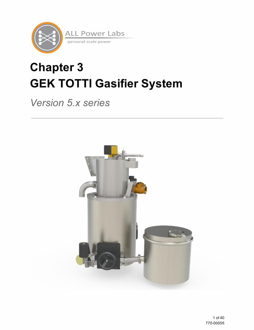
Chapter 3 GEK TOTTI Gasifier System Version 5.x series
1 of 40 77000055
Table of Contents
Overview Notes about nomenclature and terms
Feedstock, Fuel Syngas, Wood gas, Producer gas TOTTI, Pyrocoil, PyroReactor Gasifier, Reactor Hearth, Reduction Bell
Feedstock Feed System Hopper Cyclone and Drying Bucket Auger and Fuel Level Switch
Annotated Figure A GEK TOTTI Gasifier with ash collection vessel Annotated Figure B GEK TOTTI Gasifier with ash collection vessel, cont. Annotated Figure C Gas Cowling and PyroReactor Annotated Figure D Gasifier cross section Annotated Figure E Detail of Hearth and Grate Basket GEK Gasifier Reactor
Air inlet Air Lines Air Nozzles Lighting Port Projected Hearth Thermocouples Thermocouples of the Power Pallet
Grate Basket Shaker and Pratio Reading pressure values on the PCU Pressure Ratio Ranges and Conditions for Grate Shaker Control
Ash Handling Ashout Auger Motor, and clearing jams
Gas filtration system Cyclone Packed Bed Filter
Packing the gas filter Warning: do not operate with filter drum empty
Changing the filter media Flare
Blowers
2 of 40 77000055

Igniter Maintenance
Warning: Maintenance Hazards Carbon Monoxide Reestablishing airtight seals Frequent Maintenance Items Infrequent Maintenance Items
Clinkers in the grate basket Purging Soot from the Drying bucket Blower Maintenance Hopper Maintenance
Feed System Maintenance Gas Filter Maintenance Cyclone Maintenance
Troubleshooting Testing the fuel level switch Testing the Thermocouples Testing for leaks
Tables of Symptoms Hopper Auger Cyclone Gas filter Flare Air inlet Difficulty starting and operational problems Pratio problems Temperature related problems
3 of 40 77000055

Overview
The GEK TOTTI (Gasifier Experimenter’s Kit, Tower of Total Thermal Integration) is the gasifier system at the heart of the Power Pallet. This document will introduce the major subsystems of the GEK TOTTI gasifier in the sequence that starts from the feedstock hopper, proceeding through the drying bucket and reactor, and ends with the gas filter.
Notes about nomenclature and terms The following are some terms you may come across in our product literature, videos, and in the course of speaking with our sales and support personnel which should be clarified to preclude confusion.
Feedstock, Fuel
The GEK TOTTI Gasifier onboard the Power Pallet is a refinery that takes crude biomass in the hopper and refines it into a cleanburning gaseous fuel for the engine, while producing charash as a waste product. In engineering parlance, material fed into a refinery to drive a chemical process would be called feedstock, and the refined product going into the engine would be called fuel. However, from the perspective of the user of the Power Pallet, the machine is fueled by biomass. Because of this, you may find the terms feedstock and fuel used interchangeably. For example, the paddle switch on top of the PyroReactor that regulates the feeding of biomass into the PyroReactor is called the fuel level switch (see Annotated Figure A), but in most of our literature, the biomass is referred to as feedstock.
Syngas, Wood gas, Producer gas
The terms syngas (short for synthesis gas), wood gas, town gas and producer gas can be found in various literature on gasification. Each term has a few implications that differentiate it from the others:
syngas (synthesis gas) refers to a gas mixture of CO (carbon monoxide) and H2 (hydrogen) produced by reduction reactions where carbon is the reducing agent. Syngas is often used as a chemical precursor for the synthesis of other organic chemicals. Because of its use as a precursor for chemical synthesis in industry, this term usually implies a level of purity and concentration not seen in gas produced by airaspirated biomass gasifiers.
wood gas refers to gas produced by the gasification of wood. Wood gas is also rich in CO and H2, but may also contain tar gases, and may be diluted with nitrogen gas if the gasifier was aspirated with atmospheric air. However, since the Power Pallet does not necessarily gasify wood, and can be used to gasify various other feedstocks such as palm kernel shells, nut shells, and other biomass, we do not use this term in order to avoid implying the need for wood.
producer gas is a term generic enough to encompass wood gas, syngas, and other produced gasses.
4 of 40 77000055
We will be using the term producer gas throughout our documentation because it most accurately describes the product from our gasifier.
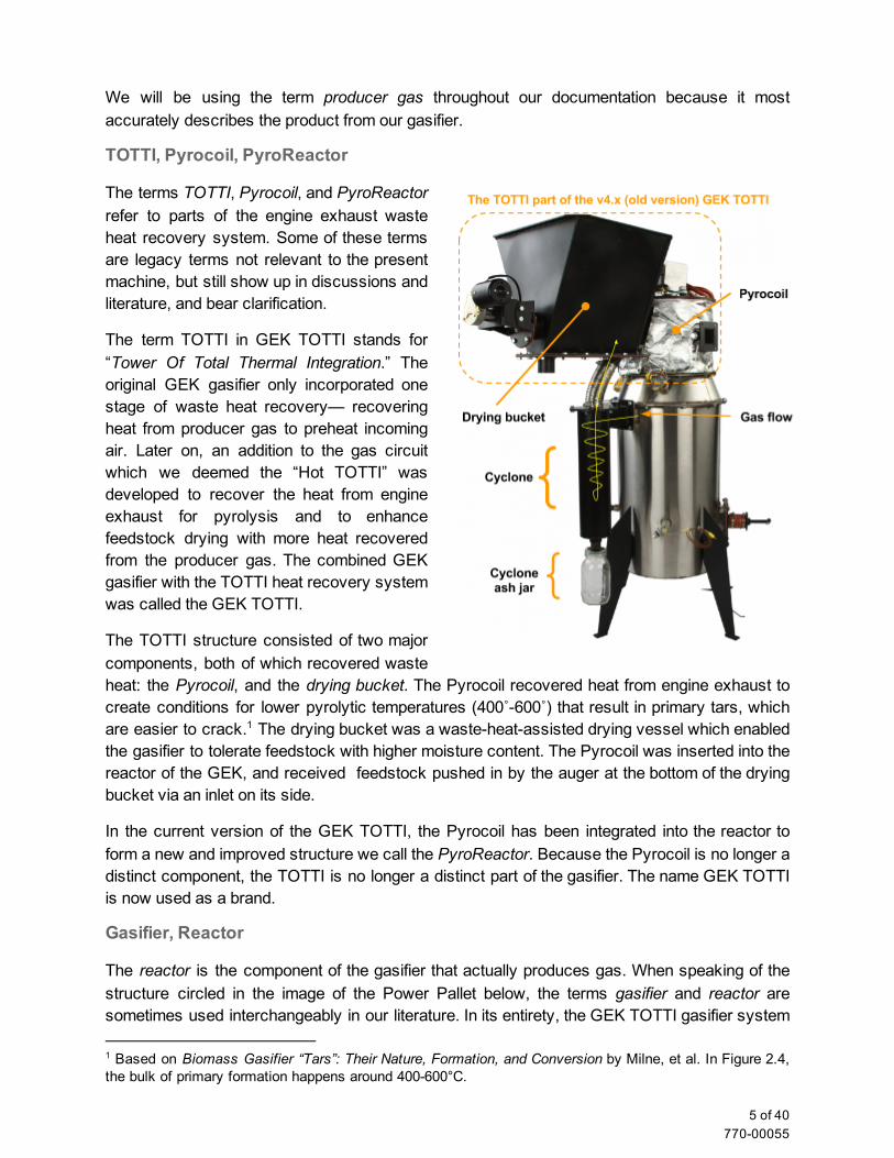
TOTTI, Pyrocoil, PyroReactor
The terms TOTTI, Pyrocoil, and PyroReactor refer to parts of the engine exhaust waste heat recovery system. Some of these terms are legacy terms not relevant to the present machine, but still show up in discussions and literature, and bear clarification.
The term TOTTI in GEK TOTTI stands for “Tower Of Total Thermal Integration.” The original GEK gasifier only incorporated one stage of waste heat recovery— recovering heat from producer gas to preheat incoming air. Later on, an addition to the gas circuit which we deemed the “Hot TOTTI” was developed to recover the heat from engine exhaust for pyrolysis and to enhance feedstock drying with more heat recovered from the producer gas. The combined GEK gasifier with the TOTTI heat recovery system was called the GEK TOTTI.
The TOTTI structure consisted of two major components, both of which recovered waste heat: the Pyrocoil, and the drying bucket. The Pyrocoil recovered heat from engine exhaust to create conditions for lower pyrolytic temperatures (400˚600˚) that result in primary tars, which are easier to crack. The drying bucket was a wasteheatassisted drying vessel which enabled 1
the gasifier to tolerate feedstock with higher moisture content. The Pyrocoil was inserted into the reactor of the GEK, and received feedstock pushed in by the auger at the bottom of the drying bucket via an inlet on its side.
In the current version of the GEK TOTTI, the Pyrocoil has been integrated into the reactor to form a new and improved structure we call the PyroReactor. Because the Pyrocoil is no longer a distinct component, the TOTTI is no longer a distinct part of the gasifier. The name GEK TOTTI is now used as a brand.
Gasifier, Reactor
The reactor is the component of the gasifier that actually produces gas. When speaking of the structure circled in the image of the Power Pallet below, the terms gasifier and reactor are sometimes used interchangeably in our literature. In its entirety, the GEK TOTTI gasifier system
1 Based on Biomass Gasifier “Tars”: Their Nature, Formation, and Conversion by Milne, et al. In Figure 2.4, the bulk of primary formation happens around 400600°C.
5 of 40 77000055

includes the feedstock hopper, the drying bucket, the PyroReactor, the gas cowling, the cyclone, the gas filter, and the flare system. The portion circled in the following graphic shows the PyroReactor installed into the gas cowling; these together form the structure that is referred to as the gasifier or reactor when speaking of components of the Power Pallet.
Hearth, Reduction Bell
The term reduction bell may appear in our literature or in postings on our online forums. This term is a legacy term and does not apply to the current generation of the GEK TOTTI gasifier. In the original GEK gasifier, reduction reactions were primarily contained in a truncated coneshaped device called the reduction bell. In subsequent revisions of the design, the reduction bell became integrated with another truncated cone that contained the combustion zone. This combined combustion/reduction structure was known as the hearth, which was used interchangeably with the term reduction bell. The old hearth is shown below, next to the new hearth. The new hearth carries out reduction throughout the grate basket, and does not have a reduction bell; as such, the term reduction bell is now obsolete.
6 of 40 77000055
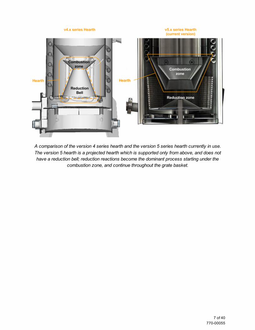
A comparison of the version 4 series hearth and the version 5 series hearth currently in use. The version 5 hearth is a projected hearth which is supported only from above, and does not have a reduction bell; reduction reactions become the dominant process starting under the
combustion zone, and continue throughout the grate basket.
7 of 40 77000055
Feedstock Feed System
Hopper The Power Pallet comes with a hopper barrel for holding feedstock. The hopper is attached to the top of the drying bucket with a silicone gasket and bolts. The hopper barrel lid is sealed at the top with a lever lock. A puff bung (a pressure relief valve) is threaded in the hopper barrel lid to release the pressure from puff events in the rare case where flame backpropagates and ignites combustible gases that may have diffused back into the hopper.
Cyclone and Drying Bucket The producer gas exits the reactor between 250˚400˚C and enters the cyclone for dust removal. The cyclone behaves like those used for dust separation in vacuum cleaners: gases spin in a descending vortex, then ascend through a central tube while the heavier suspended particles separate out by centrifugal force and descend into the cyclone ash can. After the cyclone, the gas flows through a passage between the double walls of the drying bucket ; this 2
heat exchange stage recovers waste heat to dry the feedstock while simultaneously cooling the producer gas to temperatures suitable for the filter and engine. This specialized drying stage enables the Power Pallet to tolerate feedstocks with moisture contents as high as 30% when
2 This feature is called the drying bucket because the original GEK TOTTI’s drying stage was shaped like a bucket. The feature and name were kept even after the geometry changed in subsequent versions.
8 of 40 77000055

powering a high load. The gas does not come in contact with the drying feedstock; only heat is exchanged between the gas and the feedstock. In addition to improving heat exchange, the baffles between the walls of the drying bucket also help any suspended dust settle out of the gas stream.
The GEK TOTTI is intentionally designed with a structural separation between the drying zone from the pyrolysis zone. This results in more efficient tar cracking and cleaner producer gas by allowing the drying and pyrolyisis to occur at different and more optimal temperatures.
Auger and Fuel Level Switch The auger assembly, located toward the bottom of the drying bucket, includes a 12VDC motor that is powered by the 12 starter battery (not included) on the Power Pallet, and a flexible steel auger helix. The flexible auger is able to deal with some inconsistencies in feedstock and affords a greater margin of safety in the case of fuel jams. Feedstock outside of the recommended size range of ½” to 1 ½” size are difficult for the auger system to handle. The auger may not be able to handle longer slivers, easily entangled pieces, or cubeshaped feedstock. Any feedstock outside of the specified parameters may cause jams, bridging or other problems downstream of the auger regardless of how well the auger itself moves the feedstock.
The auger spiral is installed at a slight angle (about 5˚) downward so that it meets the bottom floor of the drying bucket as it enters into the reactor. Because of friction from this contact, the auger may cause a screeching noise against the drying bucket if the drying bucket is empty.
The auger motor is controlled by the fuel level switch (See Annotated Figure A); this switch leaves the auger motor on until feedstock pushes up against the stainless steel paddle of the switch, which turns the auger motor off. The sensitivity of the fuel level switch can be adjusted via the preloading spring located under the cover of the fuel level switch housing.
The PCU detects the auger state and current to make determinations about auger performance. The logic can detect possible bridging, low fuel states, or jamming conditions. The auger circuit has two relays, one for controlling forward motion and one for reverse (used to help dislodge jams), each protected by 15A fuses located adjacent to the relays on the relay board under the PCU. (See Chapter 4: Automation Assembly for details.)
See the troubleshooting guide at the end of this chapter for instructions on testing the fuel level switch.
9 of 40 77000055
Annotated Figure A GEK TOTTI Gasifier with ash collection vessel
Label Description Label Description
1 Fuel Level Switch 5 Ash removal system motor
2 Inlet from drying bucket 6 Reactor access door
3 Exhaust inlet to PyroReactor 7 Air inlet with check valve
4 Grate basket shaker motor 8 Ash collection vessel
10 of 40 77000055
Annotated Figure B GEK TOTTI Gasifier with ash collection vessel, cont.
Label Description Label Description
1 Ignition port (shown with extension) 4 PyroReactor viewport
2 Outlet to exhaust stack 5 Cyclone
3 Ash removal port 6 Cyclone ash can
11 of 40 77000055
Annotated Figure C Gas Cowling and PyroReactor
Label Description Label Description
1 Gas cowling (inner vessel) 5 Inlet from drying bucket
2 Gas cowling insulation shroud 3 6 Air lines
3 Ashout auger 7 Projected hearth
4 Grate basket shaker motor
The PyroReactor fits into the gas cowling in the assembled gasifier.
3 Insulation fits between inner vessel and insulation shroud. (Not shown in figure.)
12 of 40 77000055
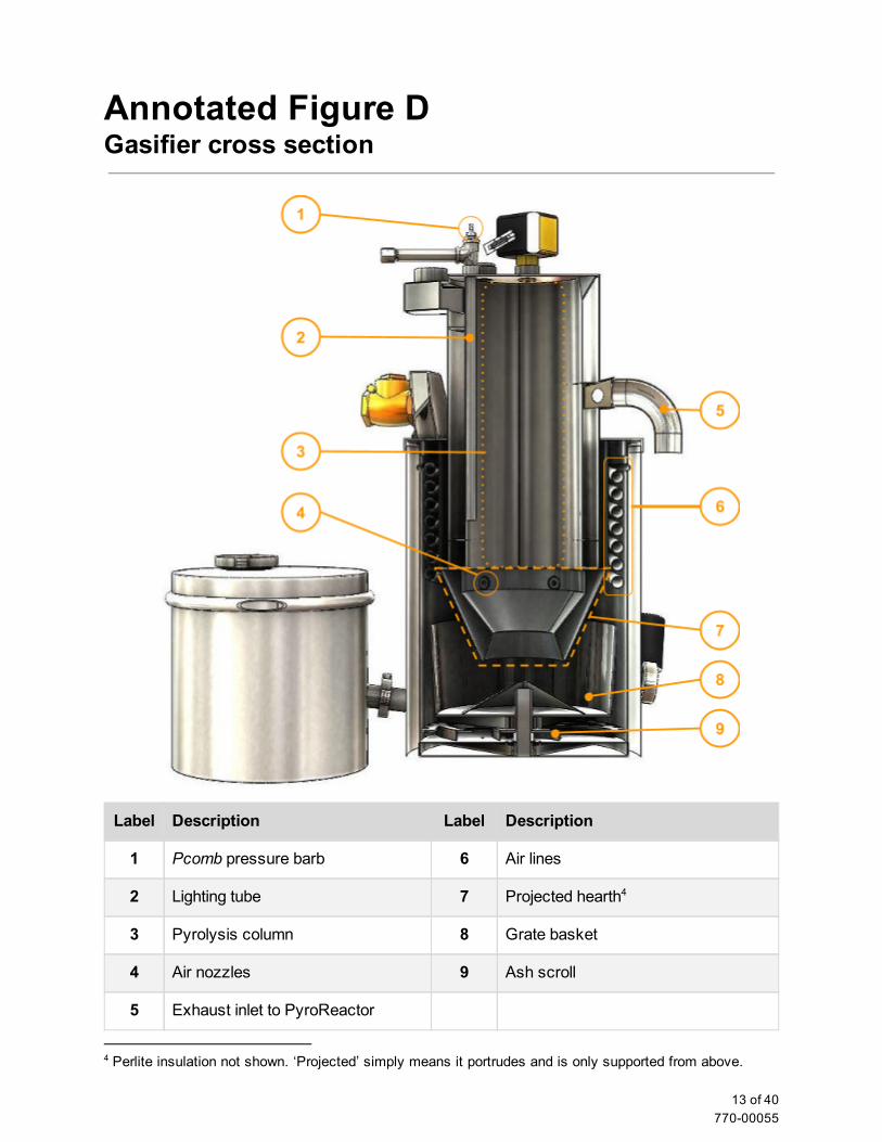
Annotated Figure D Gasifier cross section
Label Description Label Description
1 Pcomb pressure barb 6 Air lines
2 Lighting tube 7 Projected hearth 4
3 Pyrolysis column 8 Grate basket
4 Air nozzles 9 Ash scroll
5 Exhaust inlet to PyroReactor
4 Perlite insulation not shown. ‘Projected’ simply means it portrudes and is only supported from above.
13 of 40 77000055

Annotated Figure E Detail of Hearth and Grate Basket
Label Description Label Description
1 Reactor access door 4 Activator cone
2 Ashout auger 5 Scroll plate
3 Grate basket 6 Ash collection vessel
14 of 40 77000055
GEK Gasifier Reactor Please refer to the annotated figures on the prior pages for images of the parts described below.
Air inlet (See Annotated Figure A) The air inlet is a check valve allows air to enter the system when the gasifier is operating and under suction, but does not allow expanding hot producer gas to escape out through the inlet during shutdown.
Air Lines (See Annotated Figures C and D) After entering the air inlet, the air is divided among the five corrugated air lines that spiral around the outside of the reactor. The air lines are the first stage of waste heat recovery; they preheat the incoming air while cooling the producer gas. The recovered heat increases the temperature of incoming air to about 600˚C, which contributes to hotter combustion and improved tar cracking.
Air Nozzles (See Annotated Figure D) The air nozzles experience the hottest temperatures in the reactor as they introduce the air into the combustion zone; temperatures in the range of 1200˚C are often found directly in front of the nozzles. The air nozzles are oriented directly at the center of the column, right above the projected hearth.
Lighting Port (See Annotated Figure B) This port allows the operator to light the feedstock in the reactor with a small propane torch during startup. This port is to be closed when the temperature indicated for the display variable Trst (Temperature at the restriction) on the PCU display is 100˚C or above.
Projected Hearth (See Annotated Figure D) The projected hearth is the heart of the version 5 of the GEK TOTTI gasifier, which is used on the Power Pallet version 1.08. This structure begins at the bottom of the pyrolysis column and projects into the grate basket. Its shape regulates the flow of solids and gasses for the key chemical processes of gasification— combustion, tar cracking and reduction.
Combustion occurs in the area above the restriction in the projected hearth; a portion of the tar gases and charcoal are combusted by the introduction of preheated air. The restriction in the hearth funnels all of the combustion gases and unburned tar gases together to homogenize the temperature while causing the tar gases to flow through a concentrated hot spot of about 800˚900˚C, resulting in efficient tar cracking—the thermal decomposition of these tars into CO and H2 gas. Tar cracking is necessary for reducing the tar content of the gas and to make the gas compatible with internal combustion engines; even though tar gases are combustible, they
15 of 40 77000055
can badly foul an engine by condensing into a thick sticky substance, and must either be burned, cracked, or filtered out to protect the engine from fouling.
Reduction is an endothermic process that converts the CO2 and H2O, produced during the combustion of tar gasses and charcoal produced during pyrolysis, into clean burning gases that are suitable for use in the engine. The carbon from the hot charcoal in the reduction zone has a very high oxygen affinity, and will react with CO2 and H2O according to the following reactions:
CO2 + C + heat → 2CO
H2O + C + heat → CO + H2
The CO and H2 (and some methane, CH4) are the combustible gases that make up approximately 4050% of the volume of the producer gas; the rest of the volume consists of nonflammable N2 from the air aspirating the gasifier, and any unreduced CO2 and H2O.
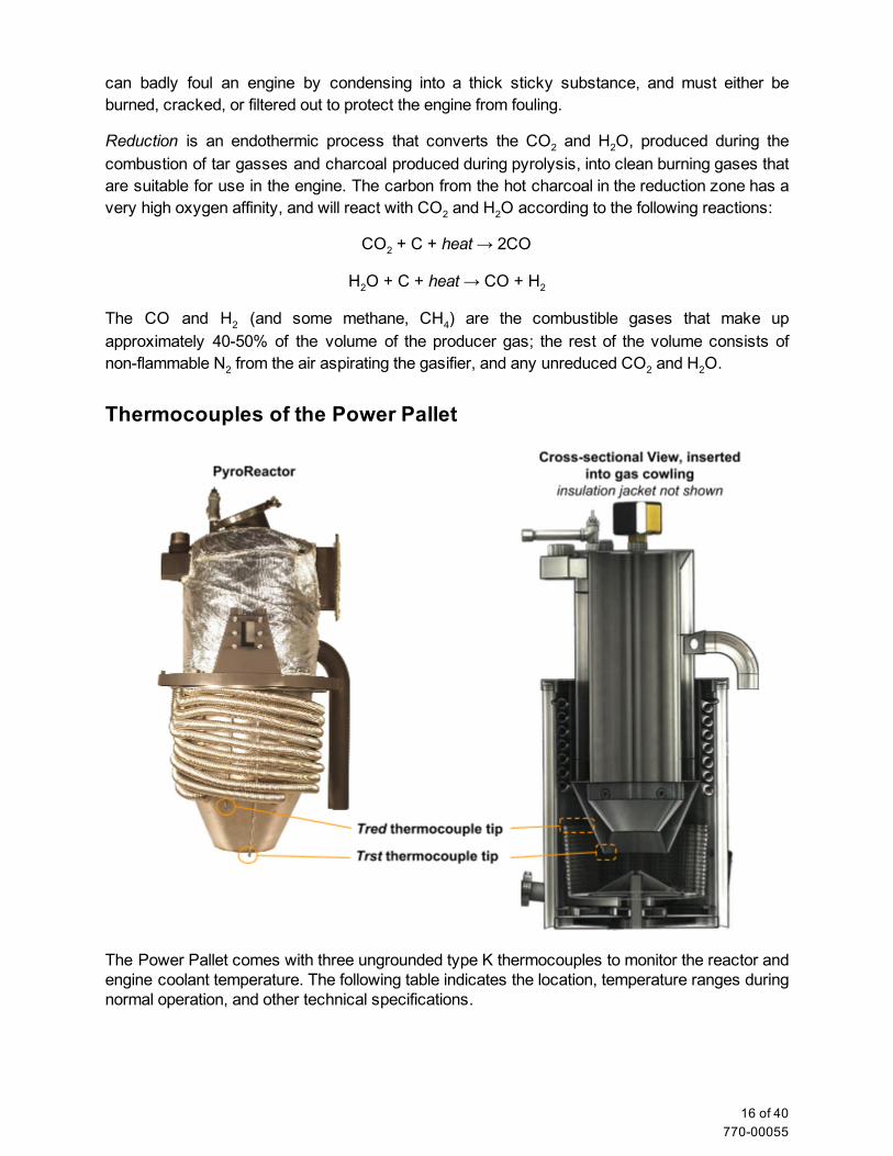
Thermocouples of the Power Pallet
The Power Pallet comes with three ungrounded type K thermocouples to monitor the reactor and engine coolant temperature. The following table indicates the location, temperature ranges during normal operation, and other technical specifications.
16 of 40 77000055
Table of Thermocouples
Display Variable: Trst Tred Tcoolant
Abbreviation of: Temperature at the restriction
Temperature of reduction Temperature of coolant
Specific Location Inside a steel sleeve; measures under the restriction of the hearth
Inside a steel sleeve; measures at the top of the grate basket
Top of engine coolant circuit, before coolant enters radiator.
Steadystate operating temp.
800˚–1000˚C 700˚–800˚C <100˚C
PCU Port T0 T1 T2
Thermocouple Specs Ktype, 1/16'' dia. x 24'' L
Ktype, 1/16'' dia. x 24'' L
Ktype Pipe Plug Probe
¼” dia
See the troubleshooting guide at the end of the chapter for instructions on how to test the thermocouples.
Grate Basket Shaker and Pratio
Onboard the Power Pallet, the only direct influence the PCU exerts on the gasifier is the timing and triggering of the grate basket shaker. A reciprocating mechanism driven by the grate 5
basket shaker motor causes the basket to rapidly rotate back and forth about 15˚ on its vertical axis, and is programmed to shake the grate for a period of three seconds once every five minutes. The shaking of the grate basket serves two purposes:
1. the periodic shaking cause the column of char bearing down on the activator cone (see Annotated Figure E, item 4) to settle and descend down and radially outwards into the grate basket as the char in the basket is consumed by reduction reactions. The settling of char into the basket gradually moves char through the combustion zone, preventing any char from residing in the hottest portion of the combustion zone for too long. The agitation of the char pieces and the shorter residence time in the hot zone reduces the risk of ash fusion and clinker formation.
2. the reciprocating motion causes ash and small particles of char to migrate down toward the bottom of the basket, where the smallest pieces fall through the holes to be removed as charash.
5 Other control loops onboard the Power Pallet include: the fuel switch and fuel auger control loop, which keeps the gasifier loaded with feedstock the oxygen sensor and air servo lambda control loop, which regulates the airfuel ratio for the engine the MPU and engine governor control loop, which maintains the AC frequency and regulates the engine suction on the gasifier. Gas production increases in proportion with suction.
The MPU to governor loop is independent of the PCU; the lambda loop doesn’t exert control on the gasifier.
17 of 40 77000055
Besides the periodic shaking, which is timed, the PCU also determines whether small char pieces are choking the flow of gas through the char basket by calculating Pratio (Pressure ratio, displayed as Pratioon the PCU screen), which is a parameter that indicates how much of flow restriction is being imparted on the gas by the char bed.
Pratio is calculated as the following:
where Pcomb stands for the pressure above the combustion zone, and Preact stands for the pressure in the reactor after the gas has passed through the grate basket. They are displayed as Pcomband Preacton the PCU screen. The following graphic indicates where these two pressure readings are taken from.
When Pratio is too low, it indicates flow restriction due to small char pieces; to correct for this flow restriction, the programming accelerates the countdown timer to trigger grate shaking sooner in order to purge the small pieces of char. When Pratio is too high, it indicates that bridging is
18 of 40 77000055
occurring inside the reactor, and is preventing char from filling the grate basket.
The variables from which regulate the countdown timer for the grate shaker and how to adjust them are explained in Chapter 5: Software.
The pressure readings on the Power Pallet are as follows:
Display variable: Pcomb Preact Pfilt
Abbreviation of: Pressure at the combustion zone
Pressure of the reactor Pressure at the filter
Specific Location Reading taken at the top of ignition tube, which leads to the top of the combustion zone. See Annotated Figure D.
Reading taken at the gas outlet from the reactor right before it enters the cyclone.
Reading taken at the top of the filter.
PCU barb P2 P0 P1
Reading pressure values on the PCU The numbers the PCU uses to represent the magnitude of vacuum for its pressure readings stand for measurements in a rather unusual unit: tenths of an inch of water column. The use of this unit of vacuum pressure comes from the legacy of the manually operated GEK gasifiers, which had water filled manometer tubes indicating the level of vacuum, as measured off of a scale marked off in inches. These units happen to be very conveniently scaled for the purpose of operating our gasifiers, since most of the pressures encountered in our gasifier fall between 1 and 12 inches of water column.
The following table shows the various ranges that the pressure measurements can fall under, and the interpretation of what these various values of Pratio.
Pressure Ratio Ranges and Conditions for Grate Shaker Control
Pressure Ratio (Pratio) Condition
<30
Lower boundary: gas flow when Pratio is <30 is likely to be restricted due to fine char accumulating in the grate basket. This condition may also be caused by clinkers.
3060 good: ideal operating conditions
>60 Upper boundary: reduction bell is empty, or feedstock is too coarse; possibly out of feedstock, or feedstock is bridging in reactor
The design of the version 5 GEK TOTTI reactor has largely eliminated low Pratioproblems. However, if you encounter bad Pratioswhile operating your Power Pallet, please see the
19 of 40 77000055
troubleshooting section at the end of this chapter for how to address problems indicated by Pratio. Low Pratiosusually indicate that small char pieces are accumulating in the grate basket, whereas high Pratiosusually indicate that bridging somewhere in the column is preventing char from descending into the grate basket.
It is possible to manually turn the grate shaker on and off via the buttons and user interface of the PCU. See the chapter on Automation for this procedure.
Ash Handling
The ash handling system of the v5 GEK TOTTI consists of the scroll plate, the ashout auger and its motor, and the ash collection vessel. (See Annotated Figure E for the top/ghosted view of what the ash handling system looks like. All of the items in this section refer to this annotated figure.) As the grate basket is shaken, char ash accumulates on the floor of the reactor under the basket. Once there, the following sequence removes the charash:
the scroll plate periodically rotates and pushes the charash out towards the walls of the gas cowling
the scroll plate also pushes charash that is already against the walls of the gas cowling along the walls until it falls into the opening on the side of the auger tube. (This opening resides behind the reactor access door facing the inside of the reactor.)
the auger pushes the char up the tube toward the ash collection vessel, where it accumulates.
The ash collection vessel has enough capacity to store the char ash from approximately 24 hours of Power Pallet operation, with variation due to load and feedstock qualities.
Ashout Auger Motor, and clearing jams Both the ashout auger and the scroll plate are driven by the ashout auger motor. The motor turns the auger, and the auger turns the scroll plate by pushing against the teeth along the edge of the scroll plate. In the case of an obstruction jamming the moving parts, a current sensing circuitry detects the resistance against the motor and the PCU cycles the motor back and forth to clear the blockage. If the blockage cannot be cleared by cycling, the machine will sound an alarm and indicate this blockage on the PCU. Such blockages may need to be cleared manually.
Before manually clearing an obstruction in the ash handling system, the operator should ensure good ventilation in the work area; clearing jams in the ash handling system involves opening the reactor, which may expose the operator to carbon monoxide if there is insufficient ventilation. First turn off the Power Pallet and let it fully cool down, then open the reactor access door. Let any gases in the reactor vent out and away, then scoop out any char near the access door. The operator should be able to find any obstructions by reaching around the auger tube and feeling along the edge of the opening, where hard material may have become pinched between the auger and the edge of the opening in the tube. Visual inspection may reveal obstructions preventing the scroll plate from turning. Ensure an airtight seal when replacing reactor access door; air leaks are hazardous to the machine.
20 of 40 77000055
Gas filtration system
The gas that emerges from the reactor will contain fine particulates, some uncracked tar gases, and water vapor. To mitigate these contaminants, the v5.x GEK TOTTI gasifier has a much improved reactor design that optimizes tar cracking and offers maximal area for gas percolation through the char, lessening high speed flow near the char bed that is more likely to entrain fine particles. However, on the occasions where the gasifier may not be operating in its ideal temperature range for tar cracking, and to capture any residual dust that does become entrained in the gas stream, the system must still protect the engine from these contaminants. It does so by removing dust using the cyclone, filtering out tar with the packedbed filter, and collecting condensation from the cooling producer gas using a condensate vessel.
Cyclone After the producer gas leaves the gasifier, it is directed into the cyclone, where it cools and spins to separate out particles of charcoal dust and condensation from the temperature drop. The condensate and particulates descend and accumulate in the cyclone ash can at the bottom. (See Annotated Figure B) The can, which has enough capacity to support 24 hours of operation, should be emptied each time before starting the Power Pallet. When reattaching the cyclone ash can, it is important to establish an airtight seal, since air leaks are hazardous to the gasifier.
Packed Bed Filter The packed bed filter is a 25 gal (94 liters) canister that is to be filled with sifted biomass or charcoal as its filter media. The filter separates out any particulates, tar that survived tar cracking, or condensate that failed to be captured through the cyclone; as the producer gas ascends through the filter, it cools further and condenses residual tars onto the sifted biomass.
The filter comes with two perforated disc screens; one to hold the filter media off the bottom of the filter canister, and one to hold down the two oiled foam discs that come with the filter, which rest on top of the filter media to trap dust particles. The top perf disc is especially important because it holds the foam discs down against the suction of the engine. Without this disc, the vacuum from the engine will pull the foam into the gas outlet, causing a serious bottleneck for the gas to travel through that will ultimately choke the engine.
21 of 40 77000055

Perforated discs and foam filters that come with the gas filter.
Packing the gas filter
1. Set one of the screens on the tabs that are about 5 inches (13 cm) above the bottom. This 5 inch space below the filter media bottom grate is reserved for collecting condensate in the filter. The level of condensate can be checked through the condensate level indicator tube. Condensate may be drained through the gas inlet at the bottom of the filter.
22 of 40 77000055
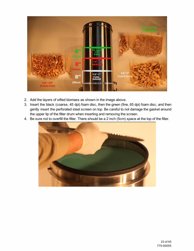
2. Add the layers of sifted biomass as shown in the image above. 3. Insert the black (coarse, 45 dpi) foam disc, then the green (fine, 65 dpi) foam disc, and then
gently insert the perforated steel screen on top. Be careful to not damage the gasket around the upper lip of the filter drum when inserting and removing the screen.
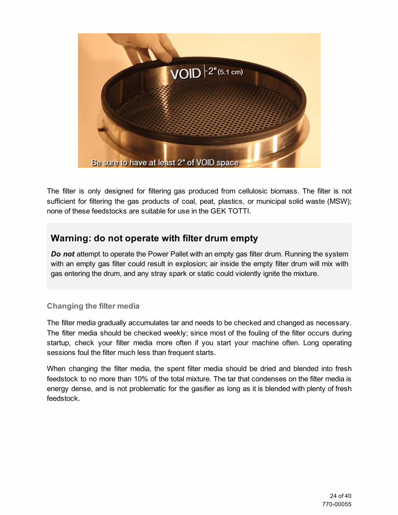
4. Be sure not to overfill the filter. There should be a 2 inch (5cm) space at the top of the filter.
23 of 40 77000055
The filter is only designed for filtering gas produced from cellulosic biomass. The filter is not sufficient for filtering the gas products of coal, peat, plastics, or municipal solid waste (MSW); none of these feedstocks are suitable for use in the GEK TOTTI.
Warning: do not operate with filter drum empty Do not attempt to operate the Power Pallet with an empty gas filter drum. Running the system with an empty gas filter could result in explosion; air inside the empty filter drum will mix with gas entering the drum, and any stray spark or static could violently ignite the mixture.
Changing the filter media
The filter media gradually accumulates tar and needs to be checked and changed as necessary. The filter media should be checked weekly; since most of the fouling of the filter occurs during startup, check your filter media more often if you start your machine often. Long operating sessions foul the filter much less than frequent starts.
When changing the filter media, the spent filter media should be dried and blended into fresh feedstock to no more than 10% of the total mixture. The tar that condenses on the filter media is energy dense, and is not problematic for the gasifier as long as it is blended with plenty of fresh feedstock.
24 of 40 77000055
Flare
The gases produced during the startup process are too rich in tar to be burned in an engine, so they are cleanly burned off in the flare until the reactor is hot enough to produce clean gas. The flare is designed to burn the tar gases with sufficient heat and oxygen such that the flare exhaust is clean and smokefree.
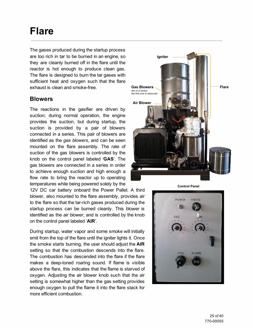
Blowers The reactions in the gasifier are driven by suction; during normal operation, the engine provides the suction, but during startup, the suction is provided by a pair of blowers connected in a series. This pair of blowers are identified as the gas blowers, and can be seen mounted on the flare assembly. The rate of suction of the gas blowers is controlled by the knob on the control panel labeled ‘GAS’. The gas blowers are connected in a series in order to achieve enough suction and high enough a flow rate to bring the reactor up to operating temperatures while being powered solely by the 12V DC car battery onboard the Power Pallet. A third blower, also mounted to the flare assembly, provides air to the flare so that the tarrich gases produced during the startup process can be burned cleanly. This blower is identified as the air blower, and is controlled by the knob on the control panel labeled ‘AIR’.
During startup, water vapor and some smoke will initially emit from the top of the flare until the igniter lights it. Once the smoke starts burning, the user should adjust the AIR setting so that the combustion descends into the flare. The combustion has descended into the flare if the flare makes a deeptoned roaring sound. If flame is visible above the flare, this indicates that the flame is starved of oxygen. Adjusting the air blower knob such that the air setting is somewhat higher than the gas setting provides enough oxygen to pull the flame it into the flare stack for more efficient combustion.
25 of 40 77000055
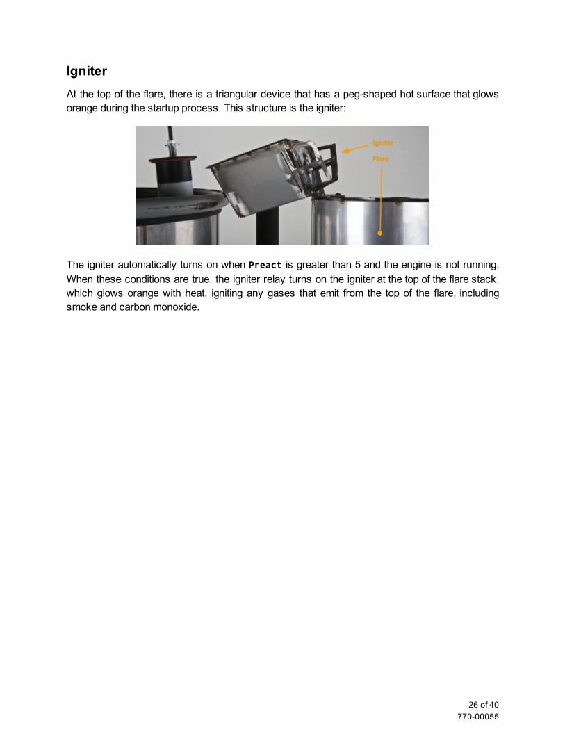
Igniter At the top of the flare, there is a triangular device that has a pegshaped hot surface that glows orange during the startup process. This structure is the igniter:
The igniter automatically turns on when Preactis greater than 5 and the engine is not running. When these conditions are true, the igniter relay turns on the igniter at the top of the flare stack, which glows orange with heat, igniting any gases that emit from the top of the flare, including smoke and carbon monoxide.
26 of 40 77000055
Maintenance
Warning: Maintenance Hazards The gas circuit is under vacuum pressure and at high temperatures during operation; doing any of the above while the machine is hot will introduce air into the gas circuit where it can mix with hot combustible gases, cause internal fires and explosions, and/or release enough carbon monoxide to seriously harm the user.
While the gasifier is hot (whether in operation or stopped), do not
remove the ash collection vessel open the ash inspection view port open the reactor access door remove the cyclone ash can
These operations must not be done until the exposed parts of the gas circuit, such as the cyclone, are cooled to the point of being safe to the touch. Cooling may take half an hour or more, depending on ambient temperatures.
Carbon Monoxide The gas left in the gas circuit after the machine has cooled down will still be rich in carbon monoxide, which is a poisonous gas as well as a fire hazard. Carbon monoxide exposure is also a risk when refilling the hopper. Always have adequate ventilation and do not do Power Pallet maintenance in the presence of open flames and sparks. Be sure to have the carbon monoxide detector near by when maintaining the machine to alert you to dangerous concentrations of carbon monoxide.
Reestablishing airtight seals Everything that can be unsealed and opened by the Power Pallet operator in the course of maintenance must be resealed with an airtight seal because air leaks are hazardous to the machine. Examples of such seals include
the hopper lid, the cyclone ash can, the gas filter lid the hose connections to the filter and its lid the reactor access door the ash collection vessel connection and ash removal port the pyrocoil viewport
Air leakage can cause internal fires that are hard to detect until irreversible damage has been done to the machine.
27 of 40 77000055
Frequent Maintenance Items The GEK TOTTI gasifier system on the Power Pallet has regular maintenance requirements that differ in how frequently they need to be carried out depending on the specific feedstock, load and other usage dynamics. The most frequently required maintenance items are:
Refilling the hopper: up to 24 times per day under high loads. The Power Pallet consumes biomass at a rate roughly proportional to its electrical output. The approximate rate of conversion is 1.2 kg of feedstock to 1kWh of electricity. Under extended periods of high load, the hopper will need to be refilled several times. When refilling the hopper, do so quickly and reseal the hopper; the gasifier does not operate efficiently when the hopper is open because air leaks in through the feedstock rather than entering through the preheating system. Extended open hopper operation is hazardous because the combustion zone will migrate up towards the air source, and can result in a fire in the hopper.
Emptying the cyclone ash can: once per day, before each start. The cyclone ash can has enough capacity to collect the fine particulates from 24 hours of operation with most fuels. It should be emptied before each operating session, while the machine is cool.
Emptying the ash collection vessel: once per day. The GEK TOTTI’s ash collection vessel has enough capacity to support 24 hour runtimes. It should be emptied while the machine is cool. Emptying the ash vessel is described below.
Replace filter media: up to once per week The filter media in the filter drum accumulates tar, particularly during startup. If your feedstock is particularly tarrich, and you start your Power Pallet very often, you will need to replace your filter media fairly often. The exact frequency required varies with feedstock and usage characteristics, and can only be determined by experience. If pressure drop between Pfilt(magnitude of vacuum pressure at the filter) and Preact
(magnitude of vacuum pressure in the reactor after the reduction zone) is regularly greater than 30, the filter is likely to be due for fresh media.
There are other frequent maintenance items related to other components of the Power Pallet; refer to the other chapters for details.
Infrequent Maintenance Items Clinkers in the grate basket Clinkers (fused clumps of minerals and ash) may accumulate in your grate basket due to high temperature operation with mineral rich feedstocks. If you observe problems with your reduction reactions or gas quality, you may need to manually remove the clinkers from the reactor.
To remove clinkers, open the reactor access door when the machine is off and cool to the touch, take hold of the handle of the gate on the grate basket, and lift it. Rake the material out of the grate basket. If clinkers are present, they will look like dark rocks or oysters:
28 of 40 77000055
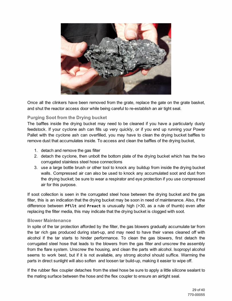
Once all the clinkers have been removed from the grate, replace the gate on the grate basket, and shut the reactor access door while being careful to reestablish an air tight seal.
Purging Soot from the Drying bucket The baffles inside the drying bucket may need to be cleaned if you have a particularly dusty feedstock. If your cyclone ash can fills up very quickly, or if you end up running your Power Pallet with the cyclone ash can overfilled, you may have to clean the drying bucket baffles to remove dust that accumulates inside. To access and clean the baffles of the drying bucket,
1. detach and remove the gas filter 2. detach the cyclone, then unbolt the bottom plate of the drying bucket which has the two
corrugated stainless steel hose connections 3. use a large bottle brush or other tool to knock any buildup from inside the drying bucket
walls. Compressed air can also be used to knock any accumulated soot and dust from the drying bucket; be sure to wear a respirator and eye protection if you use compressed air for this purpose.
If soot collection is seen in the corrugated steel hose between the drying bucket and the gas filter, this is an indication that the drying bucket may be soon in need of maintenance. Also, if the difference between Pfiltand Preactis unusually high (>30, as a rule of thumb) even after replacing the filter media, this may indicate that the drying bucket is clogged with soot.
Blower Maintenance In spite of the tar protection afforded by the filter, the gas blowers gradually accumulate tar from the tar rich gas produced during startup, and may need to have their vanes cleaned off with alcohol if the tar starts to hinder performance. To clean the gas blowers, first detach the corrugated steel hose that leads to the blowers from the gas filter and unscrew the assembly from the flare system. Unscrew the housing, and clean the parts with alcohol. Isopropyl alcohol seems to work best, but if it is not available, any strong alcohol should suffice. Warming the parts in direct sunlight will also soften and loosen tar buildup, making it easier to wipe off.
If the rubber flex coupler detaches from the steel hose be sure to apply a little silicone sealant to the mating surface between the hose and the flex coupler to ensure an airtight seal.
29 of 40 77000055
Hopper Maintenance While no regular scheduled maintenance is required, the hopper barrel must maintain a vacuum seal during operation. An air leak anywhere on the hopper will cause the combustion zone in the reactor to slowly migrate upwards toward the added source of air, resulting in poor gas quality. Sustained air leaks in the hopper during operation are also dangerous because the mixture of air and producer gas has the potential to ignite in the hopper, causing an internal fire.
To ensure gastight sealing around the bolts, dip the bolts into the silicone RTV when installing the bolts. Tighten the bolts around the hopper evenly at about 10 lbs of torque. The corner bolts often needed to be tighter than the other bolts due to the ridge on the bottom face of the hopper.
Feed System Maintenance When introducing new feed stocks with different characteristics, make sure the auger and
fuel level switch interacts properly. Open the PyroReactor viewport (see Annotated Figure B, item 4) and turn the system power on. Check to see if the auger is pushing fuel into the reactor. When the reactor is full, make sure the feedstock is actuating the fuel level switch easily without compacting.
Due to variability in feedstock characteristics, the customer may need to adjust some of the settings. Setting adjustments and customizations include: over and under current span for auger motor in the PCU menu, and fuel level switch tension spring.
If the reactor has been run completely out of feedstock, there is a chance that the temperatures at the top of the lid could exceed the normal operating temperatures of the fuel level switch. Be sure to test the fuel level switch after low fuel events to make sure it is working properly before the next run.
While rare, its possible for some feed stocks to become stuck behind the switch and prevent the auger from turning off. Before starting the reactor, make sure the switch is not obstructed by any material or hardened tar residue behind the joint of the paddle.
Gas Filter Maintenance The gas filter media is likely to be in need of replacement when the difference between the Preacand Pfilterreading is greater than 30 while running the engine for the Power Pallet. This indicates that the pressure drop across the filter is greater than three inches of water column; open the lid of the filter and empty the media onto a tarp. Allow the media to dry, and add the used filter media back into the feedstock at a proportion not exceeding 10%.
The filter foam disks are to be cleaned with warm soapy water, dried and reoiled for reuse. The two filter media grates may need to be scraped clean with a wire brush when cleaning, typically the bottom grate will get clogged up first before the top layers of filter media.
The either bung located at the bottom of the gas filter or the connection for the gas hose to drain any condensate out of the filter. Please do not pour the condensate into rivers and streams. Dispose of this as if it were engine oil. Alternatively, this tar rich condensate may be sprayed over fresh feedstock and be left to dry to recover the energy content of the tar.
Make sure that the bulb seal gasket is seated properly on the top ring of the gas filter. Low
30 of 40 77000055
temperature silicone sealant may be used to hold the gasket in place or be used for sealing any other leaks if present.
Cyclone Maintenance Make absolutely sure that the cyclone ash can is fitted air tight. Any leaking of air into the
cyclone can pose risk of explosion. Build up can accumulate inside the cyclone over time. Ideally use a large bottle brush or other tool to scrape the insides of the cyclone. To detach the cyclone, remove the four bolts attached to the gas cowling and the bolts at the cyclone adapter at the top of the cyclone.
It is normal to see dry char or liquid condensate collecting in the cyclone ash can.
31 of 40 77000055
Troubleshooting
Testing the fuel level switch To test the fuel level switch, access the testing mode screen on the PCU. In the fuel level switch test mode, it should give the following values:
Numbers less than 600 means the switch is depressed by feedstock. Numbers near 900 means the switch is untouched, and feedstock level is low . 0 means there's no signal and the circuit should be checked for loose connections.
Testing the Thermocouples The thermocouples may need to be tested to check to see if they are giving correct readings. To test a thermocouple on the Power Pallet, turn on the Power Pallet, unscrew and extract the thermocouple while leaving it plugged in, then apply a small flame such as a flame from a lighter to the tip of the thermocouple and watch for the temperature reading on the PCU to rise. If the thermocouple reading does not rise when heat is applied to the thermocouple, the thermocouple itself is probably damaged, and should be replaced.
Testing for leaks Air leaks constitute an entire class of problems that can arise anywhere there is a joint or interface or even a faulty hose. Because the entire gas circuit is under vacuum pressure when the machine is operating if there is a leak, air will leak into the gas circuit rather gas leaking out. Because of this, testing for leaks is not always easy. The most common ways to detect a leak are:
Observing the emission of smoke when the machine is shut down— Immediately after the Power Pallet is shut down, the system will no longer be under vacuum pressure. There will be enough residual heat in the system to continue pyrolysis, so the biomass in the pyrolysis column will continue to smoke. The smoke will eventually migrate throughout the system. If you observe smoke leaking from any point, the location where the smoke is exiting the gas circuit is usually the location of the leak.
Observing excessive heat anywhere on the gas circuit during operation— if there is a leak, and air is being introduced into the gas circuit while the machine is operating, it is not unusual for internal fires to ignite around the leak. Rapid heating surrounding a likely leak point indicates that an internal fire is burning near an air leak. Undetected air leaks can cause a jet of flame to burn right through whatever structure is in front of the leak. The machine should be stopped as soon as possible if this is the case to avoid irreversible damage.
32 of 40 77000055

An example of localized overheating due to an internal fire caused by an air leak from a poorly
resealed interface.
Scanning for leaks with a mechanic’s stethoscope, or other detection methods— The most reliable way to detect leaks is to use one of the detection methods listed below to detect air rushing out of a leak as a little bit of positive pressure is applied to the gas circuit while the machine is fully cooled down. To apply positive pressure, shut both of the valves leading out of the gas filter and to apply a low level of positive pressure to the gas circuit (as little as ½ psi, no more than 2 psi) using an adapter and a restricting valve with a pressure dial connected to a source of compressed air. Alternatively, you can connect some other source of blown air, such as shop vacuum cleaner’s air outlet. To detect leaks, the following methods all work quite well: (WARNING: Be sure to totally purge the gas circuit with the gas blowers before you attempt any positive pressure leak tests; if there is a leak, carbon monoxide left in the gas circuit can leak out and asphyxiate the technician testing the machine.) Spray soapy water over likely leak points. If there is a leak, you will see bubbles
form around the leak. Be sure to wipe away the soapy water when you finish testing for leaks.
Slowly move a smoking incense stick past potential leak points. If there is a leak, you will see the stream of air disturb the smoke from the incense. WARNING: the All residual gases must be purged before this test. If combustible gases leak out, the smoldering tip of the incense stick may ignite the gases and cause a fire.
Slowly move a downy feather past potential leak points. The principle of this test is the same as above; you should be able to see any leak disturb the feather as you move it by.
Scan potential leak points with a mechanic’s stethoscope. The mechanic’s stethoscope is designed to concentrate and amplify the sound of any leak near the tip
33 of 40 77000055
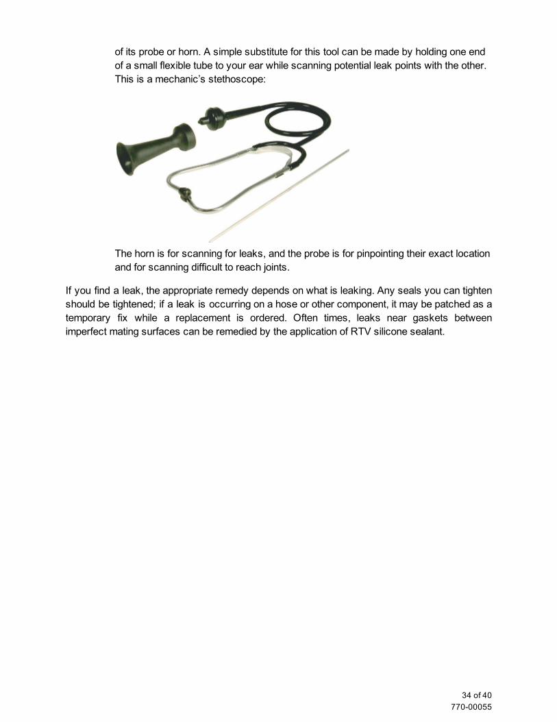
of its probe or horn. A simple substitute for this tool can be made by holding one end of a small flexible tube to your ear while scanning potential leak points with the other. This is a mechanic’s stethoscope:
The horn is for scanning for leaks, and the probe is for pinpointing their exact location and for scanning difficult to reach joints.
If you find a leak, the appropriate remedy depends on what is leaking. Any seals you can tighten should be tightened; if a leak is occurring on a hose or other component, it may be patched as a temporary fix while a replacement is ordered. Often times, leaks near gaskets between imperfect mating surfaces can be remedied by the application of RTV silicone sealant.
34 of 40 77000055

Tables of Symptoms
Hopper
Symptom Possible root cause Solution
Air leaks around hopper 1) Damaged lid gasket Align or replace lid gasket
2) Misaligned bolts or flange gasket
Align or replace drying bucket flange gasket. If leaking seen through bolt holes, apply silicone RTV around bolt hole and reinsert bolt.
Auger
Symptom Possible root cause Solution
Auger jamming 1) Feedstock is too difficult for auger
Remove any material that is over 1.5'' in length. Avoid feedstock that has a natural tendency to entangle or other natural transport difficulties.
2) Auger is bent. Disconnect the auger assembly from the drying bucket. Gently bend the auger spiral to be straight in alignment with the auger motor shaft.
3) Auger is catching on inner wall of drying bucket.
portion of the drying bucket right above the base of the auger may need to be trimmed or bent forward.
4) Fuel level switch needs adjustment.
The fuel level switch may not be actuating properly to turn the auger off in time allowing the auger to compact the fuel into the reactor. Double check that the switch works and adjust the tension spring on the fuel level switch.
5) Tar buildup around fuel switch obstructs motion
Unscrew the entire fuel switch fixture and clean out all tar with solvents.
Auger not turning on 1) Fuse needs replacement.
Check the two forward and reverse fuses for the auger on the relay board.
2) Relay needs replacement.
Replace relay on the relay board.
35 of 40 77000055
3) Fuel level switch is damaged.
Replace.
4) Tar buildup holds switch in offposition.
Unscrew the entire fuel switch fixture and clean out all tar with solvents.
Low current state for auger
1) Bridging in the hopper or drying bucket.
Check the two forward and reverse fuses for the auger on the relay board.
2) Low/No feedstock
Fill the hopper up with feedstock.
PCU is not indicating the correct auger state.
1) Current sensing not working properly
Make sure current sensor is wired correctly or current sensor may need replacing.
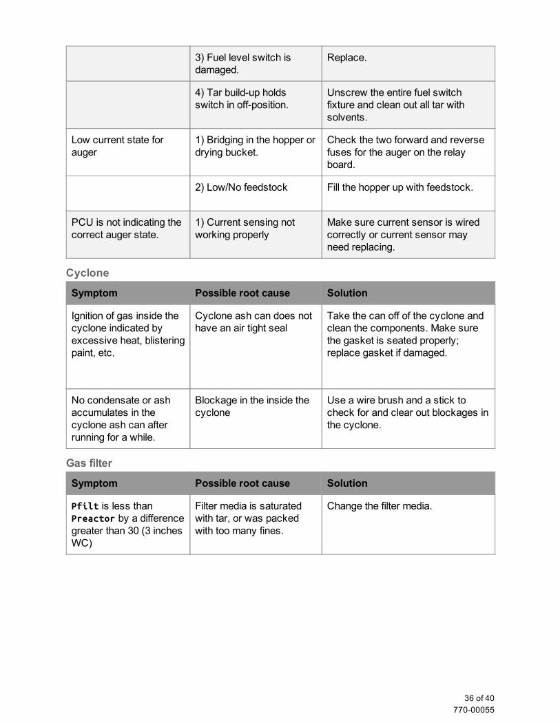
Cyclone
Symptom Possible root cause Solution
Ignition of gas inside the cyclone indicated by excessive heat, blistering paint, etc.
Cyclone ash can does not have an air tight seal
Take the can off of the cyclone and clean the components. Make sure the gasket is seated properly; replace gasket if damaged.
No condensate or ash accumulates in the cyclone ash can after running for a while.
Blockage in the inside the cyclone
Use a wire brush and a stick to check for and clear out blockages in the cyclone.
Gas filter
Symptom Possible root cause Solution
Pfilt is less than Preactor by a difference greater than 30 (3 inches WC)
Filter media is saturated with tar, or was packed with too many fines.
Change the filter media.
36 of 40 77000055

Flare
Symptom Possible root cause Solution
Too much air allowed into flare stack at low flows
Air blower gasket stuck in housing.
Adjust the gasket so that it seats properly in the gasket housing.
Flame seen above the flare stack
Flare does not have enough air; flame starved of oxygen.
Increase air blower output using the knob on the control panel.
Flare is not lighting. 1) White smoke seen as steam actually seen during start up of the reactor.
Reactor is not lit yet. White smoke is actually steam coming off of moisture in the system.
2) Improper air to fuel ratio in flare stack.
Try increasing or decreasing the air blower to achieve the right air to fuel mixture in the flare stack.
3) Igniter not working properly.
Test igniter using testing screen on the PCU. Check fuse on the relay board. Replace igniter tip if damaged.
Gas blowers are not able to achieve over 5 WC.
1) Charcoal is packing densely the grate basket
Clean out the reactor and char basket, then use correctly sized charcoal and feedstock for the second start.
2) Gas blower malfunctioning.
Check to see if both fans are operational and the fan blades are intact or fouled with tar; clean with alcohol if fouled.
3) Low battery Recharge the 12V DC battery.
Air inlet
Symptom Possible root cause Solution
Smoke seen passing through air inlet check valve when machine is off.
1) Gasifier is on an incline, causing check valve flap to fail to seal.
Level the Power Pallet.
2) Check valve flap physically obstructed or stuck open by tar.
Tap on the flap and it should fall back into place. Remove check valve and remove tar residue with alcohol.
37 of 40 77000055
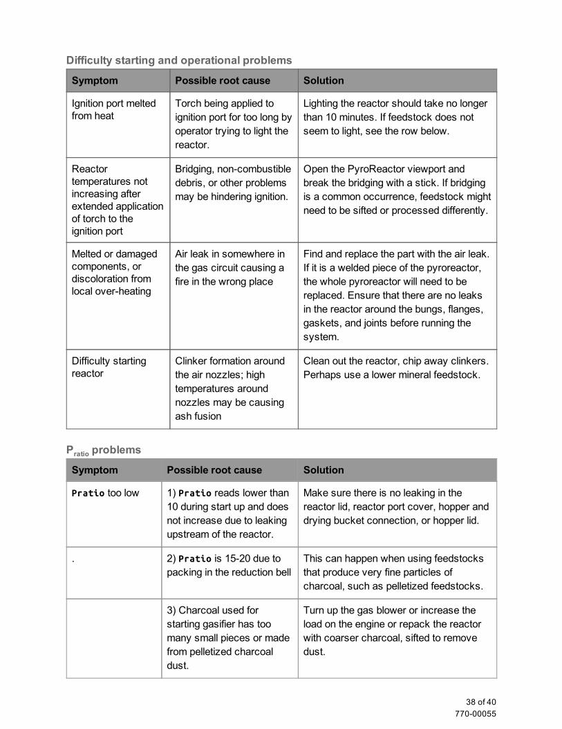
Difficulty starting and operational problems
Symptom Possible root cause Solution
Ignition port melted from heat
Torch being applied to ignition port for too long by operator trying to light the reactor.
Lighting the reactor should take no longer than 10 minutes. If feedstock does not seem to light, see the row below.
Reactor temperatures not increasing after extended application of torch to the ignition port
Bridging, noncombustible debris, or other problems may be hindering ignition.
Open the PyroReactor viewport and break the bridging with a stick. If bridging is a common occurrence, feedstock might need to be sifted or processed differently.
Melted or damaged components, or discoloration from local overheating
Air leak in somewhere in the gas circuit causing a fire in the wrong place
Find and replace the part with the air leak. If it is a welded piece of the pyroreactor, the whole pyroreactor will need to be replaced. Ensure that there are no leaks in the reactor around the bungs, flanges, gaskets, and joints before running the system.
Difficulty starting reactor
Clinker formation around the air nozzles; high temperatures around nozzles may be causing ash fusion
Clean out the reactor, chip away clinkers. Perhaps use a lower mineral feedstock.
Pratio problems
Symptom Possible root cause Solution
Pratio too low 1) Pratio reads lower than 10 during start up and does not increase due to leaking upstream of the reactor.
Make sure there is no leaking in the reactor lid, reactor port cover, hopper and drying bucket connection, or hopper lid.
. 2) Pratio is 1520 due to packing in the reduction bell
This can happen when using feedstocks that produce very fine particles of charcoal, such as pelletized feedstocks.
3) Charcoal used for starting gasifier has too many small pieces or made from pelletized charcoal dust.
Turn up the gas blower or increase the load on the engine or repack the reactor with coarser charcoal, sifted to remove dust.
38 of 40 77000055
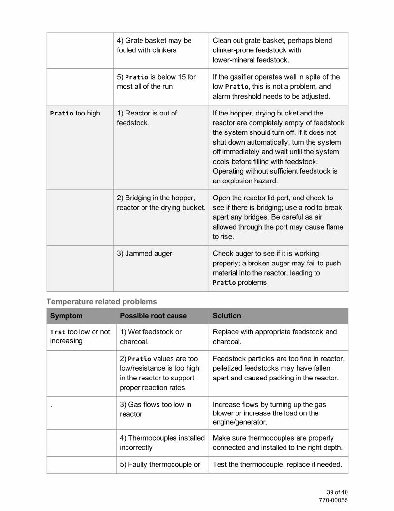
4) Grate basket may be fouled with clinkers
Clean out grate basket, perhaps blend clinkerprone feedstock with lowermineral feedstock.
5) Pratio is below 15 for most all of the run
If the gasifier operates well in spite of the low Pratio, this is not a problem, and alarm threshold needs to be adjusted.
Pratio too high 1) Reactor is out of feedstock.
If the hopper, drying bucket and the reactor are completely empty of feedstock the system should turn off. If it does not shut down automatically, turn the system off immediately and wait until the system cools before filling with feedstock. Operating without sufficient feedstock is an explosion hazard.
2) Bridging in the hopper, reactor or the drying bucket.
Open the reactor lid port, and check to see if there is bridging; use a rod to break apart any bridges. Be careful as air allowed through the port may cause flame to rise.
3) Jammed auger. Check auger to see if it is working properly; a broken auger may fail to push material into the reactor, leading to Pratio problems.
Temperature related problems
Symptom Possible root cause Solution
Trst too low or not increasing
1) Wet feedstock or charcoal.
Replace with appropriate feedstock and charcoal.
2) Pratio values are too low/resistance is too high in the reactor to support proper reaction rates
Feedstock particles are too fine in reactor, pelletized feedstocks may have fallen apart and caused packing in the reactor.
. 3) Gas flows too low in reactor
Increase flows by turning up the gas blower or increase the load on the engine/generator.
4) Thermocouples installed incorrectly
Make sure thermocouples are properly connected and installed to the right depth.
5) Faulty thermocouple or Test the thermocouple, replace if needed.
39 of 40 77000055
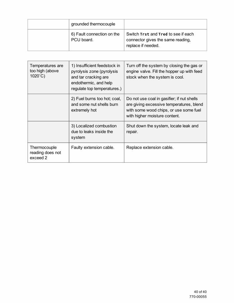
grounded thermocouple
6) Fault connection on the PCU board.
Switch Trst and Tred to see if each connector gives the same reading, replace if needed.
Temperatures are too high (above 1020˚C)
1) Insufficient feedstock in pyrolysis zone (pyrolysis and tar cracking are endothermic, and help regulate top temperatures.)
Turn off the system by closing the gas or engine valve. Fill the hopper up with feed stock when the system is cool.
2) Fuel burns too hot; coal, and some nut shells burn extremely hot
Do not use coal in gasifier; if nut shells are giving excessive temperatures, blend with some wood chips, or use some fuel with higher moisture content.
3) Localized combustion due to leaks inside the system
Shut down the system, locate leak and repair.
Thermocouple reading does not exceed 2
Faulty extension cable. Replace extension cable.
40 of 40 77000055