chapter 3 deflection type measuring instrumentseng.modern-academy.edu.eg/e-learning/comm/electrical...
TRANSCRIPT

Chapter 3 Deflection Type Measuring Instruments

• The Permanent Magnet Moving Coil (PMMC) instrument is the most common used as deflection type instruments.
Basics of the PMMC Instruments
25-Feb-18 2

PMMC Construction
25-Feb-18 3

• Permanent magnet, which generates the permanent magnetic field.
• Fixed soft iron cylindrical core which intensifiesthe magnetic field inside the permanent magnet air gap.
• Movable copper coil wound around aluminum former which can rotate around the soft iron core when a current passes through it.
• The eddy current is generated in the coil and the former when the coil rotates and therefore the required damping force is generated.
25-Feb-18 4

• Lightweight pointer, attached to the moving coil, can be deflected over a linear scale.
• Two control springs used as a source of the control force, and as a current connection to the moving coil.
• Two or three counter weights attached to the pointer to provide correct balance of the pointer such that it does not move under the effect of gravity.
25-Feb-18 5

PMMC Operation
Deflection Force
• When a current (I) passes through the moving coil the deflection torque (Tdef) is generated due to the interaction of the permanent magnet magnetic field and the moving coil magnetic field.
• The deflection torque causes the pointer to be deflected over the scale with a deflectionangle (Φ) proportional to the input current (Tdef I).
25-Feb-18 6

Control Force
• As the pointer moves the control springs generate a control torque (Tcon) proportional to the angle of deflection (Tcon Φ) and opposes the deflection torque.
• When the pointer reaches the desired deflection angle, the deflection torque equalsto the control torque.
• Consequently: the deflection angle is linearlyproportional the input current (Φ I).
25-Feb-18 7

Damping Force
• Only as the pointer moves, an eddy current is generated in the moving coil and in its former.
• Thus an eddy current damping torque is generated which minimizes or prevents the oscillation of the pointer around its exact position (deflection angle Φ)
25-Feb-18 8

Torque Equation
• When a current (I) flows in a one turn coil of dimensions (L, D) and it is situated in a magnetic field of intensity (B), then a force (F) affecting on both sides of the coil perpendicular to B and no forces affecting on the other sides of the coil parallel to B.
25-Feb-18 9

• The force is described by:
F = BIL [Newtons, Tesla, Ampere, meter]
• The force affecting on a coil of N turns is
F = BILN
• Since both forces (F) of both sides are oppositeto each other, and the distance between them is D, then they produce a deflecting torque :
Tdef = BILND = BNAI = Cdef I [Nm]
Where:
o A is the area of one turn of the coil [m2],
o Cdef (= BNA) is the deflection constant [Nm/A].25-Feb-18 10

• As Tcon Φ, then:
Tcon = Ccon Φ
o Where:
Ccon is the control (spring) constant [Nm/degree]
• At final position of the pointer:
Tdef = Tcon , then:
Cdef I = Ccon Φ
• Thus:
o Where: K (= Cdef /Ccon) is device constant [degree/A]
Φ = K I
25-Feb-18 11

Conclusion:
1- The pointer deflection is linearly proportional to I.
i.e. The PMMC scale is linear (equally spaced).
2- If the current changes its direction (negative current), the pointer will deflect off the scale (to a negative value). So the PMMC instrument is called a Polarizedinstrument (its deflection direction depends on the polarity of its input quantity).
25-Feb-18 12

Advantages of PMMC Instruments
• Linear scale (equally spaced)
• Simple, and cheap
Disadvantages of PMMC Instruments
• Polarized (can not be directly used to measure AC quantities, but rectifiers must be added to its input)
• Not sensitive (to have sensitive device the taut band suspension must be used, which is expensive)
• External magnetic fields badly affects its operation.
• Not rugged
25-Feb-18 13

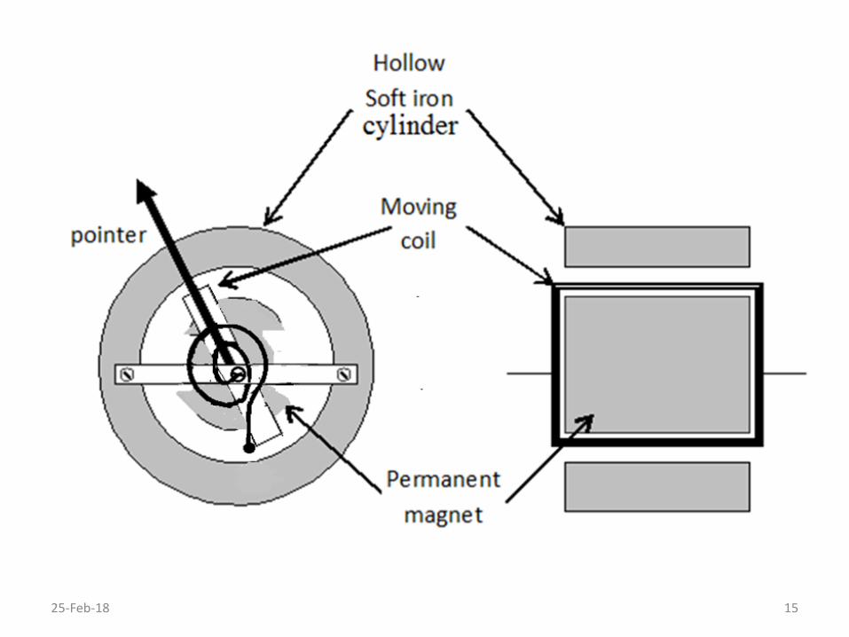
Note:
• Core magnet type PMMC construction can be used to avoid the effect of external magnetic fields .
• In this construction the moving coil (MC) and its former is rotating around a core permanent magnet (PM), and a hollow soft iron cylinder surrounds the MC and the PM to isolate them from the external magnetic fields, as shown in the next slide
25-Feb-18 14
25-Feb-18 15

# PMMC DC Ammeters
• The PMMC instrument is an Ammeter, its pointer deflects according to its input current.
• But its maximum input current is small, because its moving coil will be destroyed by high input current.
• For measuring high current (I) this instrument must be modified as shown bellow:
25-Feb-18 16

• The moving coil resistance (Rm) is shunted by a smallshunt resistor (RS).
• Therefore, the most of the input current (IS) passes through the shunt resistor and a small current (Im) passes through the moving coil.
• Thus the instrument scale is recalibrated to read the total input current (I = IS + Im) instead of the currentpassing in the moving coil (Im).
• From the previous figure we can see that:
Vm = Im Rm = IS RS , and IS = Im (Rm /RS)
Then: I = IS + Im = Im (1 + Rm /RS)
25-Feb-18 17

• Therefore , in order to read the input current (I) instead of the moving coil current (Im), the scale of the basicPMMC instrument is multiplied by the constant:
(1 + Rm /RS)
• Thus the ammeter can read a higher current by connecting smaller shunt resistance (RS)
Note:
The value of the shunt resistance (RS) can be calculated from the previous equation as:
RS = Rm [ Im / (I – Im) ]
25-Feb-18 18

Multi-Rang Ammeters
The multi shunts are connected in parallel to the moving coil of the PMMC instrument in order to build a multi range ammeter, in two different methods as follows:
• Multi-Rang Ammeters using Switched Shunts
25-Feb-18 19

• In the switched shunts method, the multi shunt resistors (RS1, RS2,…, RSn) are connected in parallel with each other and a switch selects one of them for a selected range.
• A special switch S (called make-before-break) must be used to protect the PMMC instrument.
• When the range is changed two shunt resistors are connected in parallel (the switch makes the next position before breaking the previous position).
• But if a normal switch is used, the total input currentwill pass through the PMMC instrument during the time of switching because the switch breaks the previous position before making the next position.
25-Feb-18 20

• Each shunt resistor is calculated from the equation:
RS = Rm [ Im / (I – Im) ]
Where:
– RS is the required shunt (lowest RS for highest range I)
– I is the required current range
• Therefore each shunt resistor (RS1, RS2, or RS3) will be special value resistor (constructed using many standard value resistors connected in parallel and series to get the required special value).
25-Feb-18 21

• Multi-Rang Ammeters using Ayrton Shunts
• In this method, a combination of series resistors (R1, R2, …, Rn) are as a shunt resistors and the switch selects one or more of them for the required ranges, as shown bellow:
25-Feb-18 22

• A normal switch S (called break-before-make) is used because during the range changing the current I does not pass at all in the circuit and therefore the PMMC instrument is protected.
• The required shunt resistor is calculated from the equation:
RS = Rm [ Im / (I – Im) ]
– Where RS is the required shunt resistor, and I is the required current range
– Also, RS1 = R1+R2+R3 , , RS2 = R1+R2 , RS3 = R1,
– And, Rm1 = Rm , Rm2 = Rm+R3, Rm3 = Rm+R3+R2
• Therefore only one resistor (R1) must be of special value, the others (R2 and R3) are nearly standard value resistors (constructed of smaller number of resistors).
25-Feb-18 23

Temperature Error
• The moving coil is made of a thin copper wire, its winding resistance (Rm) is changed by temperaturechanges (due to the room temperature and power dissipation in the wire).
• A swamping resistance (RSw) must be used to reduce or eliminate variation of the moving coil resistance (ΔRmT) due to the temperature changes.
• The swamping resistance (RSw) is made of a material of very small Temperature Coefficient of Resistance (TCR≈ 0), such as manganine or constantan materials.
25-Feb-18 24
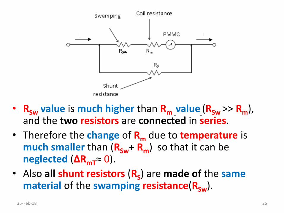
• RSw value is much higher than Rm value (RSw >> Rm), and the two resistors are connected in series.
• Therefore the change of Rm due to temperature is much smaller than (RSw+ Rm) so that it can be neglected (ΔRmT≈ 0).
• Also all shunt resistors (RS) are made of the samematerial of the swamping resistance(RSw).
25-Feb-18 25

Ammeter Resistance (Ra)
• Practically the ammeter resistance is approximately equal to the connected shunt resistance:
Ra = RS // (Rm + RSw) ≈ RS
• Thus the ammeter resistance Ra (such as RS) is smallerfor higher ranges.
25-Feb-18 26

• Because of the ammeter is always connected in series to the circuit resistance (RL) whose currentis to be measured.
• Then, In order to avoid the loading effect of the ammeter, its resistance (Ra) must be muchsmaller than all series connected resistors for lower range (RL of the shown circuit)
Ra<<RL i.e (Va << VL)
Ideally: Ra ≈ 0Ω i.e (Va ≈ 0V)
25-Feb-18 27
PMMC DC Voltmeters
• The deflection of the PMMC instrument is proportional to the current (Im), passing through its moving coil.
• If its scale is multiplied by the moving coil resistance (Rm), It will read its input voltage instead of current, thus the PMMC is converted to a DC Voltmeter.
• But the FSD of this instrument is very small (Vm) because of the very small (Im), so a high-value multiplier resistor (RS) is connected in series to its moving coil, in order to increase the range of the voltmeter, as shown in the next figure:
25-Feb-18 28

• V = Vm+ VS
• V = Im(Rm+ RS) = Im Rm [1+(RS/Rm)] = Vm [1+(RS/Rm)],
• RS = (V/Im) - Rm = Rm [(V/ImRm ) – 1] = Rm [(V/Vm ) – 1]
• Then RS/Rm = (V/Vm ) – 1
• e.g. If RS = 99 Rm , Then V = 100 Vm
25-Feb-18 29

• Therefore the scale of the basic PMMC instrument is multiplied by the constant (RS+Rm) in order to read the input voltage (V) instead of the moving coil current (Im).
• The voltmeter can read a higher voltage by connecting higher series multiplier resistance(RS).
• Also a multi range voltmeter can be made by connecting multi series multiplier resistors and a switch.
25-Feb-18 30

Multi-Rang Voltmeters
• The multi multiplier resistors are connected in two different methods in series with the moving coil of the in order to build a multi range voltmeter, as follows:
• Multi-Rang Voltmeters using Switched MultiplierResistors:
25-Feb-18 31

• The multi multiplier resistors (RS1, RS2,…, RSn) are connected in parallel with each other and a switchselects one of them series with the moving coil for a selected range.
• Each multiplier resistor is calculated from the equation:
RS = (V/Im) - Rm = Rm [ (V/Vm) – 1]
Where:– RS is the required multiplier resistor (large RS for large range ).
– V is the required voltage range.
• Therefore each multiplier resistor (RS1, RS2, or RS3) will be special value resistor (constructed using many standardvalue resistors connected in parallel and series to get the required special value).
25-Feb-18 32

• Multi-Rang Voltmeters using Series-Connected Multiplier Resistors:
• The multiplier resistors (combinations of R1, R2, …, Rn) are connected in series with each others, and with Rm
• The switch selects one or more of them for the selectedranges
25-Feb-18 33

• The required multiplier resistor is calculated from the equation: RS = (V/Im) - Rm = Rm [ (V/Vm) – 1].
Where:
– RS is the required multiplier resistor.
– V is the required voltage range.
– Also, RS1 = R1 , RS2 = R1+R2, RS3 = R1+R2+R3
• Therefore only one resistor (R1) must be of specialvalue, the others (R2 and R3) are nearly standard valueresistors (constructed of smaller number of resistors).
25-Feb-18 34

Temperature Error
• The moving coil resistance (Rm) is changed by temperaturechanges.
• As the multiplier resistor (RS), is connected in series with (Rm), and (RS >> Rm), therefore it can be considered as the swamping resistance (RSw) of the voltmeter circuit.
• To reduce (Rm) variation due to temperature changes (ΔRmT), RS is made of manganine or constantan materials having very small Temperature Coefficient of Resistance (TCR≈ 0)
• Consequently the change of (Rm) due to temperature is much smaller than RS+Rm, so that it can be neglected (ΔRmT ≈ 0).
Note:
• There is no need here to use a swamping resistance (RSw) 25-Feb-18 35

Voltmeter Resistance (RV)
• Practically the voltmeter resistance (RV) is approximately equal to the connected multiplier resistance (RS)
RV = RS + Rm ≈ RS
• i.e. the voltmeter resistance is higher for higher ranges.
25-Feb-18 36

• Because of the voltmeter is always connected in parallel with the circuit resistance (R2), whose voltagedrop is to be measured.
• Then in order to avoid the loading effect of the voltmeter, the voltmeter resistance (RV) must be muchhigher than (the parallel connected resistors for lower ranges (R2 of the above circuit )):
RV >> R2 i.e. IV << IR2
• Ideally:
RV ≈ ∞ Ω i.e. IV ≈ 0 A
25-Feb-18 37
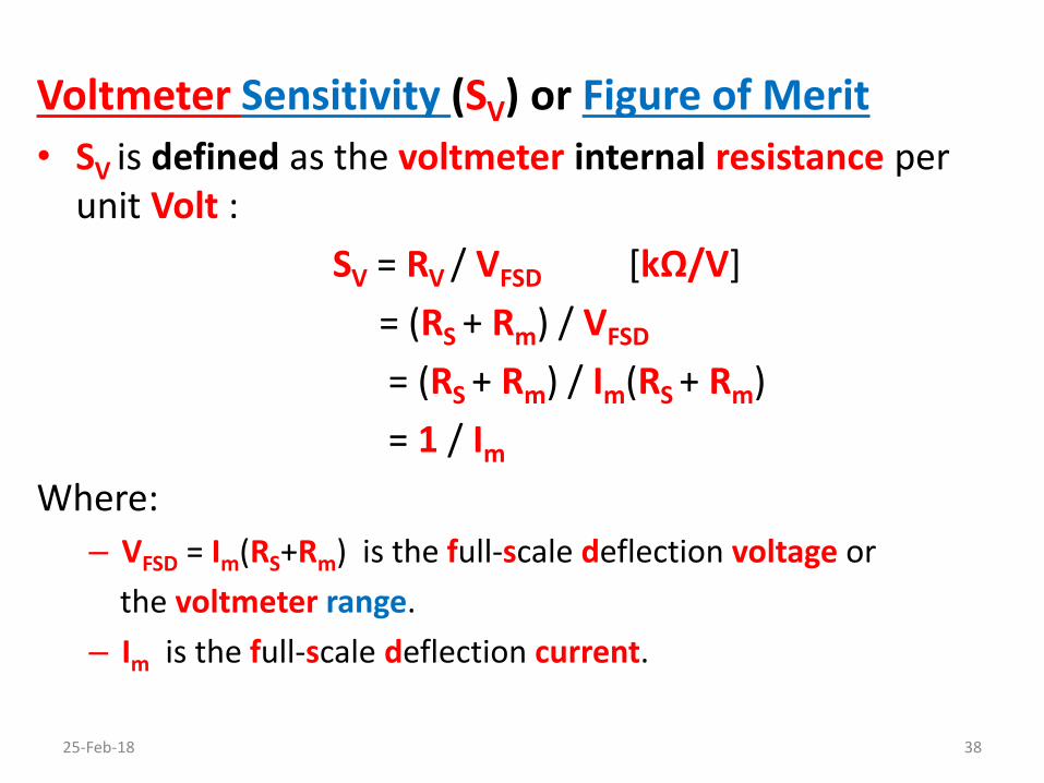
Voltmeter Sensitivity (SV) or Figure of Merit
• SV is defined as the voltmeter internal resistance per unit Volt :
SV = RV / VFSD [kΩ/V]
= (RS + Rm) / VFSD
= (RS + Rm) / Im(RS + Rm)
= 1 / Im
Where:
– VFSD = Im(RS+Rm) is the full-scale deflection voltage or
the voltmeter range.
– Im is the full-scale deflection current.
25-Feb-18 38

# AC PMMC Voltmeters• the PMMC instrument can be damaged when it is
connected to a high AC input current or voltage, although the pointer indicates zero value (the averagevalue of its AC input).
• Therefore the AC input must be converted to DC or to pulsating input of one polarity (which have not zeroaverage value)
• AC to DC conversion is done using rectifier (half wave or full wave rectifiers, using silicon or germanium diodes).
• Full wave rectification will be considered, in this chapter, to illustrate how the conventional PMMC can be used as an AC measuring instrument.
25-Feb-18 39

Full-Wave Rectifier AC Voltmeters
25-Feb-18 40
• The positive Half-cycles of the input voltage (Vp sin ωt) pass through D1, Rm, and D4 while the negative Half-cycles pass through D3, Rm, and D2 .
• Thus the input voltage is converted to a pulsatingunidirectional voltage passes in one direction through the PMMC instrument

• The pointer deflects according to its average value of the input voltage:
Vav = = 0.637 Vp
• But the scale is rescaled (calibrated) to read the Root-Mean Square value (RMS) of the input voltage:
ViRMS = = 0.707 Vp
The scale value = 0.707 Vp= 0.707 (Vav / 0.637) = 1.11 Vav
• Therefore each value of the scale is multiplied by the form factor (1.11) to be converted to RMS.
• The form factors are varied according to the shape(Waveform) of the input signal, thus the value (1.11) is correct only for sinusoidal input waveforms
25-Feb-18 41
• Therefore this type of AC voltmeters are called NON-TRUE RMS voltmeters, because the scale is rescaled due to mathematical formula considering the input waveform is pure sinusoidal.
25-Feb-18 42

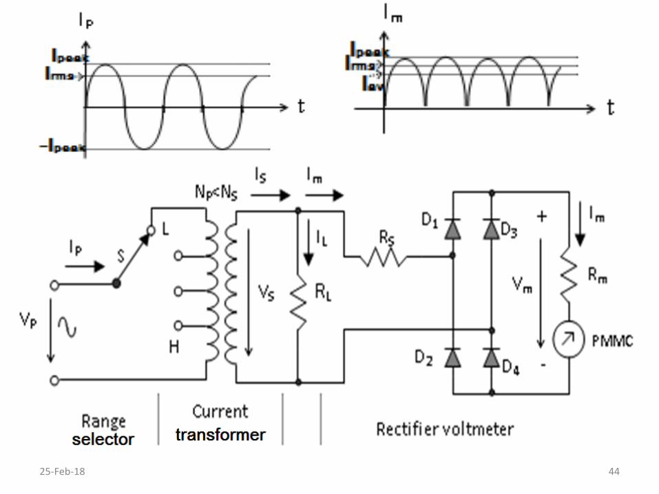
Rectifier AC Ammeters
• The circuit of AC voltmeter can be used as AC Ammeter
• But it has bad quality because of these disadvantages:1- high input resistance ( RS+ Rm).2- high input voltage is required 1.5V.3- high input current NOT ALLOWED.
• Therefore another approach must be used to convert the rectifier AC voltmeter to an ACammeter, as shown in the next slide.
25-Feb-18 43
25-Feb-18 44

Advantages of the current transformer:
• It steps up the input voltage (VS >VP) such that a very small voltage drop (VP) across the ammeter terminals (≈ 0.2 V) can operate it.
• Very small input resistance of the ammeter (resistance of the primary coil), therefore the ammeter will not affect the circuit under test.
• It steps down the input current (IS < IP) such that the ammeter can measure a high inputcurrent.
25-Feb-18 45

• The resistance RL is used to increase the rangeof the ammeter. (Im= IS- IL).
• Multi-range ammeter can be built as follows:
– Taps of primary coil, lower Np gives higher range (higher IP)
– Multi-value of RL and a switch, lower RL gives higher range.
25-Feb-18 46
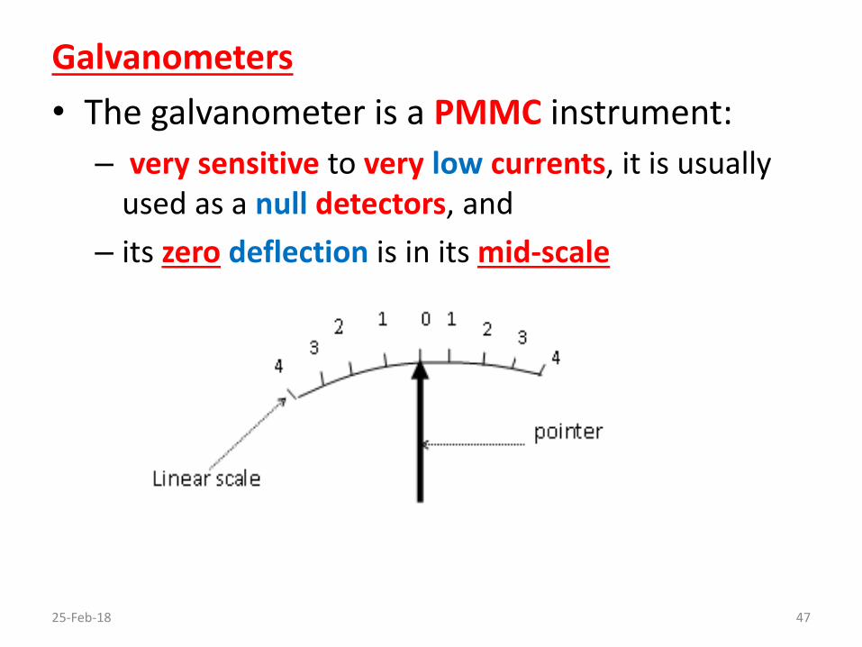
Galvanometers
• The galvanometer is a PMMC instrument:
– very sensitive to very low currents, it is usually used as a null detectors, and
– its zero deflection is in its mid-scale
25-Feb-18 47

• In order to achieve these requirements, the following modifications are made in the normal construction of the PMMC instrument:
– Taut band suspension is used to increase its sensitivity(zero friction).
– Very light weight pointer (or light beam pointer) is used.
– Critically damping eddy current must be designed, therefore the moving coil former is not used to reduce the weight of the coil, and to avoid over damping, then the eddy current damping level is adjusted using series or shunt damping resistor.
– An electronic galvanometer may be used which amplifies the current before applying it to the moving coil.
25-Feb-18 48

25-Feb-18 49
Galvanometer (modified PMMC)

Definitions Related to the Galvanometer
• Current Sensitivity (SI) [µA/mm]
It is the amount of current (µA) flowing through the instrument to give a given deflection (mm).
• Damping resistor (Rd) [Ω]
It is connected in series with instrument (Rd << sourceresistance) to control the eddy current level.
• Voltage Sensitivity (Sv) [µV/mm]
It is expressed for a given value of a critical dampingresistance (Rcd ) as follows:
SV = Rcd SI [µV/mm, Ω, µA/mm]
25-Feb-18 50

• Critical Damping Resistor (Rcd) [Ω]
It is the minimum value of the damping resistance that makes a sufficient damping with very small short level of oscillation:
Rcd = SV / SI [Ω, µV/mm, µA/mm]
• Megohm sensitivity (SMΩ) [MΩ]
It is the resistance connected in series with the instrument to restrict the deflection to one scale division for 1 V potential difference between its terminals:
SMΩ = (1 V/mm) / SI [MΩ, V/mm, µA/mm]
25-Feb-18 51
Protection of the Galvanometer
• When the galvanometer is used as a null detector (e.g., across the diagonal of a wheatstone bridge), initially high current may passes across it due to the unbalance of the bridge.
• Therefore, the galvanometer may be damaged due to this excessive unbalance current.
• Two methods may be adopted to protect it:
o Connecting Series Variable Resistor
o Connecting Shunt Variable Resistor and Switch
25-Feb-18 52

1-Connecting Series Variable Resistor:
25-Feb-18 53
• It is used to reduce the current in the galvanometer when the bridge is unbalanced. • The steps of balance adjustmentas follows:
1. Adjust the series resistance to its maximum value (VG << V).
2. Adjust the balance of the bridge (the galvanometer reads zero).
3. Reduce the value of the series resistance.4. Repeat steps 2 and 3 till the value of the series resistance
equals zero (VG = V).5. Adjust the Balance of the bridge.

2- Connecting Shunt Variable Resistor and Switch
25-Feb-18 54
• It is used to reduce the current in the galvanometer, when the bridge is unbalanced. • The steps of balance adjustmentas follows:
1. Adjust the shunt resistance to its minimum value and closeits series connected switch (IG << I).
2. Adjust the balance of the bridge (the galvanometer reads zero).
3. Increase the value of the shunt resistance.4. Repeat steps 2 and 3 till the value of the maximum value of
the shunt resistance and the bridge is balanced.5. Open the switch and adjust the balance of the bridge(IG = I)..
Series Ohmmeters
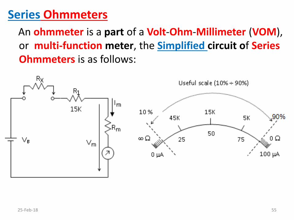
An ohmmeter is a part of a Volt-Ohm-Millimeter (VOM), or multi-function meter, the Simplified circuit of Series Ohmmeters is as follows:
25-Feb-18 55

• The Simplified circuit of Series Ohmmeters consists of:
– Internal DC battery VB
– Standard (precise) known resistor R1
– the unknown resistor RX
– the PMMC instrument.
• As: Im = VB / (RX + R1+ Rm)
• Then: RX = (VB / Im) - (R1+ Rm)
• As: R1 >> Rm
• then: Im = VB / (RX + R1)
and RX = (VB / Im) - R1 i.e.
• If RX = ∞, Im = 0.
• If RX = 0, Im = VB / R1 = IFSD25-Feb-18 56
RX 1 / Im

• If RX = Rm + R1 ≈ R1, Im = 1/2 IFSD
• If RX = 3(Rm + R1) ≈ 3R1, Im = 1/4 IFSD
• If RX = 1/3(Rm + R1) ≈ 1/3R1, Im = 3/4 IFSD
• And so on, using different known values of RX then indicating these values on the scale.
• The scale of the PMMC can be recalibrated to indicate resistance RX instead of current Im .
• The scale in the previous figure shows:
o Case of mid-scale (R1 = 15 kΩ, VB = 1.5 V)
o Non-linearity (deflection 1 / Rx).
25-Feb-18 57

• The multi-range ohmmeter can be built by using multiple values of R1 and a switch.
• Every range is referenced by its mid-scale deflection(the value of the connected R1).
• The scale is cramped at both ends and more spaced towards the mid-scale, therefore the accuracy of the ohmmeter is maximum at its mid-scale deflection, and decreases as the deflection decreases or increases than the mid-scale.
• The main disadvantage of the simplified circuit of series ohmmeter as follows: – The scale will be not correct if the battery falls because Im is
not correct at this time.
– This disadvantage is overcome by the ohmmeter with zero adjust circuit.
25-Feb-18 58

• Series Ohmmeters with zero adjust
• They are sometimes called ohmmeters with zero controlor with calibration control.
• The zero control resistor R2 is added parallel to Rm of the simplified circuit, as shown below:
25-Feb-18 59

• Therefore the description and the analysis of the simplified circuit are also applied to this circuit except that it compensates its battery voltage falls:
Im = IB - I2, I2 1/ R2
• The full-scale deflection Im (zero ohm indication) is adjusted when the ohmmeter terminals are short-circuited (RX = 0 ) by adjusting the value of R2
even if the battery (VB) falls.
• If IB decreases due to the decreasing of VB, then Im
can be kept constant by decreasing the value of I2
(by increasing R2 ).
25-Feb-18 60
• This adjustment must be firstly done each time the ohmmeter is used to compensate the falls of the battery VB.
• Therefore the scale of the series ohmmeter will remain correct even if the battery (VB) falls.
• The main disadvantage of this connection is that: the zero ohm adjustments must be also done if the range of the ohmmeter is changed.
• This disadvantage is overcome by using the practical multi-range series ohmmeter or by replacing the battery by regulated voltage supply
25-Feb-18 61
Electrodynamic Instruments
25-Feb-18 62

Basics of The Electrodynamic Instruments
Construction
25-Feb-18 63

The electrodynamic instrument is constructed of the following components:-
• Two stationary coils
Generate the stationary magnetic field, they are sometimes called field coils.
• Movable coil
Rotates inside the field coils when a current passes
through it
• Lightweight pointer
can be deflected over a non-linear scale
25-Feb-18 64

• Two control springs
used as a source of the control force (torque).
• Two or three counter weights
attached to the pointer to provide correct balance of the pointer such that it does not move under the effect of gravity.
• Air vane chamber
used to generate the air damping force (torque)
25-Feb-18 65
Operation
• When a current (I1) passes through the stationary coils and current (I2) passes through the moving coil the deflection torque (Tdef) is generated due to the interaction of the magnetic fields of the stationaryand the moving coils.
• The deflection force causes the moving coil to rotates, consequently, the pointer is deflected over the scale with a deflection angle (Φ) proportional to the multiplication of the current I1, and I2 :
Tdef I1 I2
25-Feb-18 66

• As the pointer moves the control springs generate a control torque (Tcon) proportional to the deflection angle, and opposes the deflection torque.
Tcon Φ
• When the pointer reaches the desired deflection, the deflection torque equals to the control torque:
Tdef = Tcon
• Consequently, the deflection is proportional to I1 I2, if the same current passes through both stationary and moving coils then: I1 = I2
• Thus the deflection angle is proportional to I2 :
Φ I2
25-Feb-18 67

• Only as the pointer moves, the air vane moves in the closed chamber
• Thus an air damping torque is generated which minimizes or prevents the oscillation of the pointer around its exact position or deflectionangle (Φ).
• The damping torque equals to zero when the pointer does not move.
25-Feb-18 68

Torque Equation and Scale
• The deflection torque is proportional to the magneticfields of the stationary coil (which proportional to the current I1) and the moving coil (which proportional to the
current I2) : Tdef = Cdef I1 I2
where Cdef is the deflection constant [Nm/A2]
• As Tcon is proportional to Φ: Tcon = Ccon Φ
where Ccon is the control (spring) constant [Nm/degree].
And at final position of the pointer: Tdef = Tcon
Then: Φ = K I1 I2
where (K = Cdef / Ccon) is the device constant [degree/A2]
• Thus If I1 = I2 , then: 25-Feb-18 69
Φ = K I2

Conclusion:
• The pointer deflection is proportional to I2, therefore, the electrodynamic scale is nonlinear (non-equally spaced) cramped at the lower end and more spaced towards the upper end, as shown below:
25-Feb-18 70
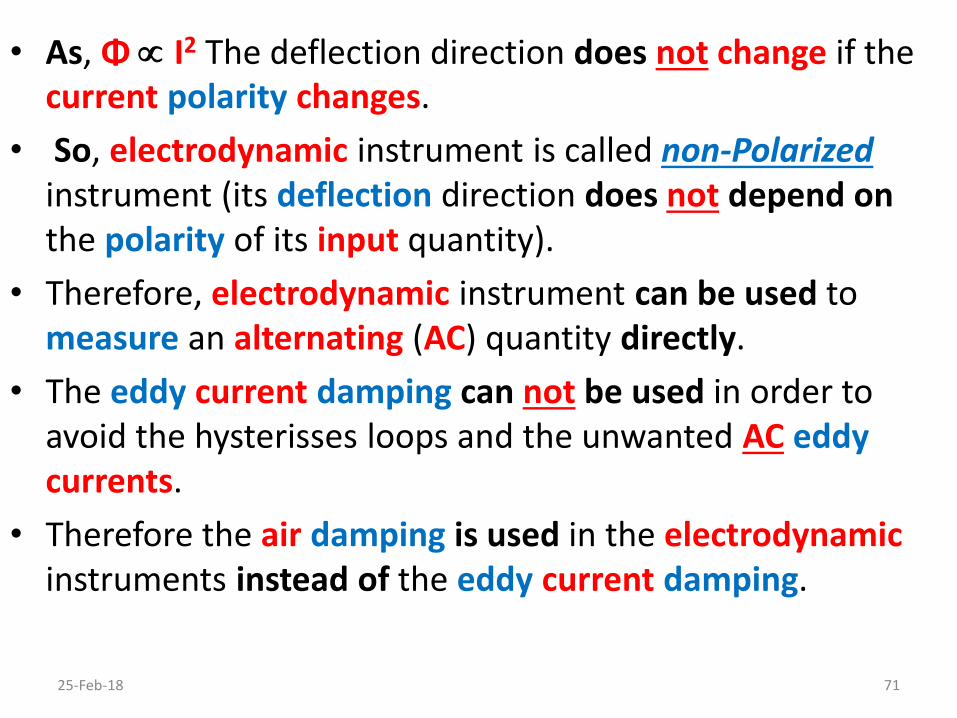
• As, Φ I2 The deflection direction does not change if the current polarity changes.
• So, electrodynamic instrument is called non-Polarizedinstrument (its deflection direction does not depend on the polarity of its input quantity).
• Therefore, electrodynamic instrument can be used to measure an alternating (AC) quantity directly.
• The eddy current damping can not be used in order to avoid the hysterisses loops and the unwanted AC eddy currents.
• Therefore the air damping is used in the electrodynamicinstruments instead of the eddy current damping.
25-Feb-18 71

• Also electrodynamic instrument is not sensitive becausethe stationary magnetic field is proportional to the measured current, not constant as in the case of the PMMC.
• Moreover electrodynamic instrument can not be used to measure high frequency AC quantities because the stationary coils impedance depends on the frequency(2πfL).
Advantages of the Electrodynamic Instruments.
– Non Polarized (can be directly used to measure AC quantities)
Disadvantages of the Electrodynamic Instruments.
– Its scale is non Linear
– Low frequency AC measurements (< 500 HZ).
– Less sensitive than the PMMC instrument 25-Feb-18 72

Electrodynamic Voltmeters
• The two stationary coils are connected in series with the moving coil.
• Since the same current is passing through stationary and moving coils, which is proportional to the input voltage V, then its deflection angle () is proportional to V2, thus its scale is nonlinear
25-Feb-18 73
circuit diagram

• A high value multiplier resistor RS is connected in series with the instrument in order to increase its range and its input resistance RV.
• The multi-range voltmeter is built by using multi-valueRS and a switch as discussed before in the DC voltmeter.
• The electrodynamic instruments are low sensitive devices i.e. the required current for the FSD voltage is much higher than the PMMC instrument.
• Therefore the voltmeter sensitivity SV, and its input resistance RV is much smaller than the PMMC AC voltmeter
Sv = 1 / IFSD = RV / VFSD
consequently its loading effect is much higher than PMMC.
25-Feb-18 74
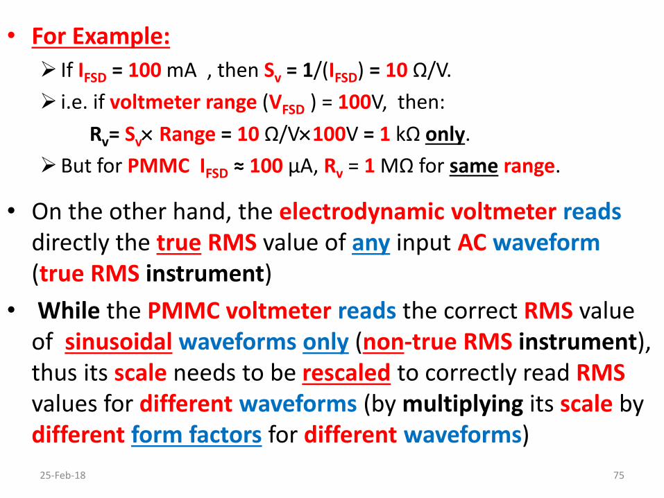
• For Example:
If IFSD = 100 mA , then Sv = 1/(IFSD) = 10 Ω/V.
i.e. if voltmeter range (VFSD ) = 100V, then:
Rv= Sv Range = 10 Ω/V100V = 1 kΩ only.
But for PMMC IFSD ≈ 100 µA, Rv = 1 MΩ for same range.
• On the other hand, the electrodynamic voltmeter readsdirectly the true RMS value of any input AC waveform (true RMS instrument)
• While the PMMC voltmeter reads the correct RMS value of sinusoidal waveforms only (non-true RMS instrument), thus its scale needs to be rescaled to correctly read RMSvalues for different waveforms (by multiplying its scale by different form factors for different waveforms)
25-Feb-18 75

• As the deflection of the electrodynamic voltmeter () is proportional to the average (mean) of square of the input AC voltage (V2)av, and its scale reading is V (not V2).
• Thus the scale reading is the square root of the average
(mean) of the square of input voltage
• Therefore the reading equals to the true Root Mean
Square (RMS) value of the input:
• That is why electrodynamic voltmeter is called a trueRMS instrument.
25-Feb-18 76

Note that:
• the same principles of building Multi-Rang of PMMCvoltmeters are used in electrodynamic voltmeters.
• Also temperature error can be avoided by using the multiplier resistor RS form material of very low TCR suchas manganine or constantan (RS is considered as a swamping resistor).
Electrodynamic Voltmeter Advantages
• Measures DC and AC voltages on the same scale without any modifications (it is used as a transfer instrument).
• Measures true RMS voltages of any AC input voltage waveforms.
25-Feb-18 77

Electrodynamic Voltmeter Disadvantages
• Nonlinear scale.
• Lower sensitive than the PMMC voltmeter.
• Lower input resistance RV than the PMMC rectifier AC voltmeter (higher loading effect).
• Very lower frequency range (fin ≤ 500 HZ) thanthe PMMC rectifier AC voltmeter.
25-Feb-18 78

Electrodynamic Ammeters
• The two stationary coils are connected in series with the moving coil.
• Since the same current is passing through stationary and moving coils, which is equal to the input current I, then its deflection angle () is proportional to I2, thusits scale is nonlinear
25-Feb-18 79
circuit diagram

• A small value shunt resistor RS is connected in parallel with the moving coil in order to increase the ammeter range.
• The multi-range ammeter is built by using multi-value RS
and a switch as discussed before in the DC ammeter.
• As the deflection of the electrodynamic ammeter () is proportional to the average (mean) of square of the input AC current (I2)av, and its scale reading is I (not I2).
• Thus the scale reading is the square root of the average
(mean) of the square of input current
• Therefore the reading equals to the true Root Mean
Square (RMS) value of the input:
25-Feb-18 80

• That is why electrodynamic ammeter is called a true RMS instrument.
• While the PMMC ammeter is called non-trueRMS instrument, because it reads the correct RMS value of sinusoidal waveforms only, thus its scale needs to be rescaled to correctly read RMS values for different waveforms (by multiplying its scale by different form factors for differentwaveforms)
25-Feb-18 81

Note that:
• the same principles of building Multi-Rang of PMMCammeters are used in electrodynamic ammeters.
• Also temperature error can be avoided by adding a highvalue swamping resistor RSw form material of very low TCR such as manganine or constantan, in series with the moving coil.
• The swamping resistor value RSw must be much higher than the moving coil resistor Rm
• Therefore the shunt resistor RS (made from very low TCR material) is connected in parallel with the series connection of Rm and RSw.
25-Feb-18 82

Electrodynamic Ammeter Advantages
• Measures DC and AC currents on the same scalewithout any modifications (it is used as a transfer instrument).
• Measures true RMS currents of any AC input current waveforms.
Electrodynamic Ammeter Disadvantages
• Nonlinear scale.
• Lower sensitive than the PMMC ammeter.
• Very lower frequency range (fin ≤ 500 HZ) than the PMMC rectifier AC ammeter.
25-Feb-18 83

Electrodynamic Wattmeters
25-Feb-18 84
Circuit Diagram
Simplified Circuit Diagram

• The two stationary coils are connected in series with the load (same current IL).
• The moving coil and a high value multiplier resistor RS
are connected in parallel to the load (same volt VL).
• Therefore the current in the stationary (field) coils is proportional to the load current IL, while the current inthe moving coil (voltage coil) is proportional to the loadvoltage VL.
• Thus the instrument deflection is proportional to the multiplication of the in-phase components of IL, and VL.
• Consequently the deflection is the DC power (PL= ILVL) or the average AC power (PL= ILrmsVLrmscos) consumed in
the load, therefore: PL i.e., its scale is linear. 25-Feb-18 85

Wattmeter connections
25-Feb-18 86
Connection 1deflection VL (IL + IV)
VL IL + Error VL IL if IV << IL
Connection 2deflection (VL + VF) IL
VL IL + Error VL IL if VF << VL

• As the wattmeter has four terminals (two terminals for each of the stationary and the moving coils)
• The user must connect them so that the connectionerror may be minimized
• In connection1:
- The voltage coil is connected directly across the load
thus the voltage drop across it equals to VL
- But the current passes in the current coil equal to the current passing in the load IL plus the current passingin the voltage coil IV i.e:
deflection VL (IL + IV)
- Therefore, this connection is the best if : IL >> IV
25-Feb-18 87

• In connection2:
- The current coil is connected directly in series to the load, thus the current passing in it equals to IL
- But the voltage drop across the voltage coil equals to the voltage drop across the load VL plus the voltage drop across current coil VF i.e:
deflection IL (VL + VF)
- Therefore, this connection is the best if : VL >> VF
25-Feb-18 88