chapter 3 creep analysis of structurest - environmental … · 2013-02-20 · chapter 3 creep...
TRANSCRIPT

Mathematical Modeling of Creep and Shrinkage of Concrete Edited by Z. Bazant :g 1988 John Wiley & Sons Ltd
Chapter 3
Creep Analysis of Structurest
3.1 INTRODUCTION
Creep and shrinkage have important effects on the behaviour of concrete structures. The deflections due to these long-term effects can be large, normally significantly larger than the short-time or elastic deflections, and the designer must make sure that the deflections are tolerable. In redundant structures creep and shrinkage cause redistributions of internal forces. These redistributions are sometimes favourable since they tend to relax the maximum stresses produced by enforced displacements or shrinkage and temperature changes, but sometimes harmful. The stresses produced by differences in creep or shrinkage among various parts of the structure, or due to a change of the structural system during construction, can cause deleterious cracking, accompanied by degradation of structural stiffness. This may further facilitate ingress of water and promote corrosion of reinforcement, which may cause spalling of concrete and ultimately a loss of serviceability of the structure.
By altering the long-time stress state, creep and shrinkage indirectly causes a change in the stress maxima for superimposed live loads. Due to the lack of plastic response (limited ductility), creep and shrinkage may exert in this manner a significant influence on the brittle failures of concrete structures. Thus, creep and shrinkage may alter the safety margin against the collapse of a structure under short-time overloads. In slender or thin structures, creep also causes a slow longtime growth of buckling deflections. Consequently, the critical loads for longtime instability may be much less than the elastic critical loads.
The purpose of this chapter is to review the methods of linear as well as nonlinear analysis of structures for the effects of creep and shrinkage and to describe the typical effects of various types of structures. The finite element analysis will be omitted from the present chapter except in so far as it directly relates to the subjects to be dealt with. This field has become so broad that it requires a separate treatment which is relegated to the next chapter.
t Principal authors: Z. P. Bazant and O. Buyukozturk. Prepared by RILEM TC69 Subcommittee 3, the members of which were O. Buyukozturk (Chairman), Z. P. BaZant, M. A. Chiorino, W. Haas, J.-E. Jonasson, J. Lazic, and W. Dilger.
217
218 ]'1>1 athernatical Modeling of Creep and Shrinkage
3.2 LINEAR METHODS
3.2.1 Basic assumptions and code recommendations
Although many strides have recently been made towards non-linear creep analysis of concrete structures, nearly all practical applications still rely on the linearity assumption, which is sanctioned by the current design code recommendations. For stresses that are constant in time, the linearity means that the strain e(t) at any time t is proportional to the stress (J and that the creep response is totally characterized by the compliance function l(t, t') (see Eq. 2.2). For time-variable stresses, the linearity assumption implies the principle of superposition, which may be expressed by the history integrals in Eqs (2.4)-(2.7), and for multi-axial stress Eq. (2.9). The current codes define the creep properties usually in terms of the creep coefficient ¢(t, t') (Eq. 2.3). This type of definition of creep properties, however, is prone to confusion, since it tempts the analyst to incorrectly combine ¢(t,1') with an elastic modulus of concrete defined in an inconsistent manner (see Section 2.5.1).
The conditions of acceptability of the linearity assumption (see Section 2.2.2) fortunately include much of the structural behaviour under service loads, except for the errors which are due to simultaneous moisture migration and cracking and are often not insignificant.
The mathematical formulae for the creep coefficient and the method for structural analysis are given in the current code recommendations such as those of the American Concrete Institute (ACI) (1983) or the CEB-FIB Model Code (1978). These formulations, which rely on traditional concepts, have the advantage of simplicity but involve a large degree of uncertainty. The 95 per cent confidence limits for the deviations from the code predictions are on the order of ± 80 per cent of the mean prediction of the creep strain. This magnitude of error is not acceptable for design, and it may be one of the reasons why, in so many instances, concrete structures suffer excessive deflections or harmful cracking and spalling well before the end of their design lifetimes.
Presently, the most comprehensive and accurate prediction model for creep and shrinkage is the BP model (Bazant and Panula, 1978) which is to a much larger extent based on physical considerations than the ACI and CEB-FIP models. This model is, admittedly, considerably more tedious to implement, but the 95 per cent confidence limits are under 30 per cent. Furthermore, by using formulae that are better justified physically, this model offers the possibility of a significant further reduction of the prediction errors by means of calibration with short-time measurements.
Even though the time that the analyst needs to implement the BP model is considerably longer than that for the current code recommendations (several hours instead of a fraction of an hour for the ACI model), the effort spent in implementing this model is still far smaller than the effort needed to carry out the structural analysis. Ideally, more time should be devoted to the determination of

Creep Analysis of Structures 219
the creep and shrinkage properties of the material than to structural analysis, because the former task involves a larger error. This error is in fact much larger than the accuracy gain due to the use of a computer.
3.2.2 Numerical methods based on hereditary integrals
Th~ ~eason. for assuming linearity is the applicability of the principle of superpOSItion-ill mathematics due to Boltzmann (1876) and Volterra (1909, 1913, 1959 see Chapter 2), and in concrete creep theory due to Maslov (1941) and McHenry (1943). According to this principle, the current strain t(t) is obtained as a hereditary integral over the previous stress history O'(t) (Eq. 2.4), and conversely for O'(t) expressed in terms of £(t) (Eq. 2.7). The inverse relation involves the relaxation function R(t, t'), which may be obtained for the purposes of design from. a simple one-line formula (Eq. 2.8) due to Bazant and Kim (1979a). The mult~axial generalization of these integral-type stress-strain relations is readily obtallled by assuming material isotropy; see Eqs (2.9-2.10).
Numerical analysis of structural response can be carried out in time steps Ilt = ti - ti+ 1 (i = 1,2,3, ... ). The integral in the stress-strain relation is replaced by a constitutive law which yields a system of linear algebraic equations to be solved at each time step. The unknowns in these equations may be the redundant internal forces, or the displacements of structural members or the nodal displacements of a finite element subdivision, depending on which method of spatial analysis is used. The integral in the stress-strain relation may be approxi.mated by a sum with various degrees of accuracy. The first applications came WIth the advent of computers during the 1960s and were motivated chiefly, but not exclusively, by the design of nuclear reactor vessels; see, e.g. the works of Rashid (1972), Bresler and Selna (1964), Selna (1967,1969), Cederberg and David (1969), Prokopovich (1963), Ghali et al. (1967) and others, in which algorithms of first-order accuracy were used. Ghali et al., for example, approximated the integral in Eq. (2.4) by the sum L,j J(t i _ liZ' tj-1/Z}LlO"j in which, the subscript i - t refers. to the middle of the time step and LlO'j = O'j - O'j-l' The first-order algoflthm was also used by Tadros et al. (1977a, b).
The algorithm which is now in prevalent use is that of Bazant (1972) (also used by Bazant and Najjar, 1973). It is based on approximating the integral in Eq. (2.5) or Eq. (2.9) by the trapezoidal rule, which leads to the incremental quasi-elastic stress-strain relations in Eqs (2.30)-(2.32). This algorithm is of second-order accuracy. The same accuracy may be achieved using the relaxation function in which case the integral in Eq. (2.7) is approximated according to the trapezoidal rule. A general-purpose computer program based on Bazant's second-order algorithm was developed by Huet (1980). A third-order method, in which the error is proportional to (1l0')3, was formulated and used by Schade (1977); in his work the integral in Eq. (2.4) or Eq. (2.9) was approximated according to Simpson's rule. .
220 Mathematical }110deling of Creep and Shrinkage
Instead of the integral based on the compliance function J(t, t'), an integral based on the impulse memory function L(t, t') (Eq. 2.5) is also possible. However, this approach is no longer used since it has been recognized to be numerically inefficient and, more importantly, to preclude an increase of the time step beyond a certain limit no matter how slow is the variation of stress and strain.
In the early work, the linear algebraic equations obtained by replacing the integral with a finite sum were formulated in terms of the structural unknowns such as the values of the redundants or the nodal displacements at subsequen; discrete times. However, as is now the general practice, it is simpler if the approximation by a sum is used to obtain an incremental quasi-elastic stress-strain relation with inelastic strain, and the structural analysis is then carried out in the same manner as for elastic materials, reducing the problem to a sequence of elasticity problems with prescribed inelastic strains (Bazant, 1966a, b, and Section 2.2.4). For the second-order or higher-order methods, the incremental elastic stiffness matrix of the structure is then different in each time step. However, certain first-order formulations have the advantage that the incremental elastic stiffness matrix changes from one time step to the next in proportion to the elastic modulus E(c), making it unnecessary to generate and assemble a new structural stiffness matrix at each time step. This advantage is lost, however, if the structure is non-homogeneous, e.g. due to differences in age, thickness, humidity conditions, etc. For large structural systems, the advantage of considerably higher accuracy of the second-order method is important because the creep analysis based on the integral-type creep law is very demanding for computer time and storage. One can greatly reduce the number of time steps by using the secondorder instead of the first-order approximation.
A matrix version of Bazant's second-order algorithm, which is however useful only for simple structures with few unknowns, was introduced by Madsen (1979) (for application in probabilistic analysis see Madsen and Bazant, 1982). In this version, instead of a step-by-step procedure the values of all unknowns at all time steps are solved simultaneously. The incremental quasi-elastic relations in Eq. (2.30) are written as one matrix relation £ = J Lllf + £0 in which £ = (£1' £2"'" £nf = a column matrix grouping the values of strains t at all discrete times t l' t 2"", tn ; Lllf, £0 = similar column matrices grouping the stress increments and the inelastic strains at all discrete times, and J = n x n square matrix. Introducing the relation If = L Lllf one obtains the combined stressstrain relation for the stress and strain values at all times in the form (Madsen, 1979):
(3.1 )
in which E - 1 = JL - 1. The advantage of this formulation is that it is easy to program. One can take an algebraic expression for an elastic solution, and by replacing 1/ E with the matrix E - lone obtains a matrix equation for the values of structural unknowns, e.g. the redundant forces, at all discrete times. In terms of

Creep Analysis of Structures 221
computer time and storage, however, this method is much less efficient than the step-by-step procedure based on the incremental quasi-elastic stress-strain relation such as Eq. (2.31). The lesser efficiency does not matter when there are only a few unknowns, but for larger structures this method would be very expensive.
The solution based on even the second-order step-by-step version (e.g. Eq. 2.30) becomes nevertheless prohibitively costly and exceeds the capacity of all but the largest computers if the structure has many unknowns (over 50), except when a supercomputer is used. For such structures it is vastly more efficient to use numerical step-by-step algorithms based on rate-type constitutive relations, which we discuss next.
3.2.3 Numerical methods based on degenerate kernel
As shown in Chapter 2, the integral-type stress-strain relation can be reduced to a rate-type stress-strain relation if the compliance function (or, more generally, the kernel ofthe hereditary integral) is approximated by a degenerate kernel. For the discrete time-step approach, one obtains the incremental elastic stress-strain relation which was already given in Chapter 2; see Eqs (2.33-2.37), which represent the rate-type creep law corresponding to an ageing Maxwell chain model, associated with a degenerate form of the relaxation function R(t, t'). A similar formulation based on the Kelvin chain model and associated with the degenerate approximation of the compliance function J(t, t') also exists (Bazant and Wu, 1974). The latter approach has been extended for two- and threedimensional analysis, and implemented in a finite element program RECON (Wium and Buyukozturk, 1984, 1985). The determination of the age-dependent elastic moduli of the Maxwell or Kelvin chain, and the choice of the associated relaxation or retardation times, was also discussed in Chapter 2, and comments were made on the numerical efficiency which is far superior to the methods based directly on hereditary integrals if large structural systems are considered. The works in which the principal contributions were presented were also discussed in Chapter 2. (Remark. A more efficient method, in which a Kelvin chain with ageindependent moduli and viscosities is used and aging is introduced by means of transformation of variables, is presented in the Addendum to Chapter 2.)
3.2.4 Simplified algebraic methods permitting any J(t, t')
Effective modulus method
This is the oldest and simplest method. Introduced perhaps first by McMillan (1916), it has been employed extensively in practice. This method, which admits any form of the compliance function J (t, t'), is usually implemented in the sense of
222 Alathematical Alodeling of Creep and Shrinkage
the total stress-strain relation
(3.2)
in which to = age at first loading,
Eeff(t, t') = l/1(t, t') = E(t' )/[l + ¢(t, t')]
is the effective modulus of elasticity (also called the sustained modulus), and D = B is defined by Eq. (2.10) for the case of isotropy. When the structural system is changed right after the time of loading, to, this method must be applied incrementally for the time interval from to to t, in which case
~I ~( 1)L\cr(t) + Ea((loȢ(l, to)J + L\EO(t) eff t, t to
(3.3)
The effective mudulus method is exact only if the stress is constant from time to at first loading up to the current time t. Otherwise, this method overestimates the effect of creep when the stress is increasing, and underestimates it when the stress is decreasing. Thus, for example, the final stress in a relaxation problem is obtained much too high, the reduction of the elastic shrinkage stress due to creep is obtained much too low, and the long-time creep buckling deflection is obtained much too high. It should also be noted that the error of the creep coefficient values obtained from the current code formulations (ACI, CEB) is often much larger than the error caused by the use of the effective modulus. More accurate methods are therefore unnecessary if these are used to determine the material properties.
All the solutions according to the effective modulus method are special cases of those for the age-adjusted effective modulus method to be discussed later.
Bafant's theorem
Jfthe mechanical strain c; - C;O is zero up to time to, then jumps to the value a, and subsequently varies from time to to t linearly with the creep coefficient, i.e.
e(t) - c;o(t) = a + c¢(t, to) or t(t) - EO(t) = a + c¢(t, to) (3.4)
then the stress for t > to varies linearly with the relaxation function and is
expressed as
a(t) = (a - c)R(t, t~) + cE(to) or Dcr(t) = (a - c)R(t, to) + cE(to) (3.5)
Here a and c are arbitrary constants, and Eqs (3.4) and (3.5) are written both for uniaxial deformation and triaxial deformation. In the latter case, matrix D is given by Eq. (2.10) for the case of isotropy, and a, c are arbitrary real constant (6 x 6) matrices.
From the theorem, discovered and proven by Bazant (1972), one readily obtains by algebraic manipulation the basic incremental stress-strain relation of
Creep Analysis of Structures 223
the age-adjusted effective modulus method given in Eqs (2.38) and (2.39). The originally presented proof may be simplified by operator formalism (Bazant, 1982b, p. 242).
Age-adjusted effective modulus method
Formulating the incremental stress-strain relation on the basis of the foregoing theorem, one finds that it is formally identical to the stress-strain relation proposed in 1967 by Trost on the basis of approximate considerations and under the restriction to a time-constant elastic modulus. Trost (1967) proposed for the time interval (to,t) the quasi-elastic incremental stress-strain relation given in Eq. (2.38), in which modulus E'(t,to) is expressed similarly to the effective modulus, but with a correction of the creep coefficient value:
(3.6)
Coefficient X was called by Trost the relaxation coefficient but was later renamed by Bazant the aging coefficient because this coefficient is almost exactly 1 when aging is assumed to be absent, whether or not stress relaxation occurs. Accordingly, modulus En was named the age-adjusted effective modulus (Bazant, 1972). The values of the aging coefficient X are usually between 0.5 and 1.0, with 0.80-0.85 as the mean estimate.
On the basis of the foregoing theorem it was shown (Bazant, 1972) that Trost's relation, originally proposed as approximate, is in fact exact in a certain sensenamely for the cases where the strain varies linearly with the creep coefficient or where the stress varies linearly with the relaxation function. It so happens that such a time variation closely approximates many typical stress histories obtained by exact solutions of the aging viscoelasticity problems. While the effective modulus method is exact only for the condition of constant stress, the method of age-adjusted effective modulus is exact for infinitely many stress histories. These stress histories need not include, as initially thought (Trost, 1967), only decreasing stress regimes typical of the stress relaxation problems, but they also include increasing stress histories such as those in long-time buckling (Baiant, 1972). Thus, coefficient X does not really introduce a correction for the stress relaxation. Rather, it introduces a correction for aging.
By a simple algebraic rearrangement of Eqs (3.4) and (3.5), it is shown that the age-adjusted effective modulus and the aging coefficient are exactly expressed as (Bazant, 1972)
E"(t t ) = E(to) - R(t, to) , 0 </>(t, to) ,
(3.7)
provided the assumption that e is linear with </>(t,t o), or that (J is linear with . R(t, to), is acceptable for the given problem. Thus we see that the aging
224 A1athematical Modeling of Creep and Shrinkage
coefficient may be calculated from the relaxation function, and vice versa. The relaxation function is easily obtained with a high accuracy by a simple
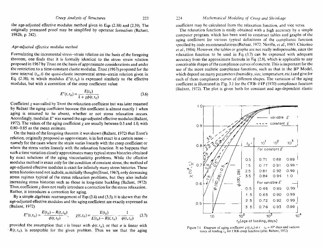
computer program, which has been used to construct tables and graphs of the aging coefficient for various typical definitions of the compliance function specified by code recommendations (Bazant, 1972; Neville, et al., 1983; Chiorino et al., 1984). However, the tables or graphs are not really indispensable, since the relaxation function to be used in Eq. (3.7) can be expressed with adequate accuracy from the approximate formula in Eq. (2.8), which is applicable to any conceivable shapes of the compliance curves of concrete. This is important for the use of the more realistic compliance functions, such as that in the BP Model, which depend on many parameters (humidity, size, temperature, etc.) and give for each of them compliance curves of different shapes. The variation of the aging coefficient is illustrated in Fig. 3.1 for the CEB-FIP (1970) compliance function (Ba1.ant, 1972). The plot is given both for constant and age-dependent elastic
1.00---,--
0.9 f---+----
0.8
.... 0 0.7 ~a"' e-><
06
0.5
10
t -0-
0.5
15
CD 2.5 N
35 8 -e-
0.5
1.5
2.5
3 5
102
variable E
constant E
101
102
103
For constant E
0.71 0.88 0.99
0.77 0.91 0.99
0.81 0.92 0.99
0.84 0.94 10
For variable E
0.46 085 0.99
0.65 0.90 0.99
0.72 0.92 0.99
0.76 0.93 0.99
103
fo(oge at loading, days)
104
Figure 3.1 Diagram of aging coefficient X (t 1 tol at t - to = 104 days and various times of loading to for CEB creep function (after Bazant, 1972)

Creep Analysis of Structures 225
modulus, revealing the influence of the variation of E to be quite significant, as pointed out by Bazant (1972).
The three-dimensional form of the quasi-elastic incremental stress-strain relation of the age-adjusted effective modulus method is obtained by generalizing Eq. (2.38):
1 .1E(t) = E"( )D.1(f(t) + .1E"(t),
t, to
provided the material is assumed to be isotropic with a constant Poisson's ratio, which is approximately true for concrete.
It has been attempted in the past to verify certain values of the aging coefficient X by comparisons with test results; see, e.g. the comparison made by Neville, Dilger and Brooks (1983-pp. 257) on the basis of the test results by Bastgen (1979). These tests, however, were of rather limited duration and the range of ages at loading did not include ages t' at loading beyond one month, so that the values of J(t, t') for higher t' were left experimentally undetermined. This fact renders the interpretation of these tests questionable because X depends on such values. Furthermore, the humidity conditions in these tests put also the linearity of creep into question so that the deviations found might not be just errors of X but of the principle of superposition itself.
The idea to correct the creep coefficient in Eq. (3.6) with some correction factor X is an old one and predates Trost and Bazant. For instance, the value X = 0.5 was used, which corresponded to the assumption that the stress varies between to and t linearly. While this is a good assumption for very short time intervals, it is poor for the very long time intervals (to, t) used in the age-adjusted effective modulus method. This may be illustrated with the help of Fig. 3.2 (Bazant, 1982); the typical stress variation in curve 3 is usually much closer to a constant stress (curve 2),
(0 ) (b)
CT 2-better
f
Figure 3.2 (a) Stress histories implied by various calculation methods; (b) stress histories expressed as a linear combination of the relaxation function
226 Mathematical Modeling of Creep and Shrinkage
implied in the effective modulus method, than to the linear stress variation (curve 1). Moreover, the stress values which matter most are those at later times, because the influence of stress at time t' upon the strain at time t increases as t' approaches t, as indicated by the memory function L(t, t') (see Eq. 2.5, the curve of which is also sketched in Fig. 3.2). For a discussion of these aspects see also Chiorino et af. (1984, pp. 104-15).
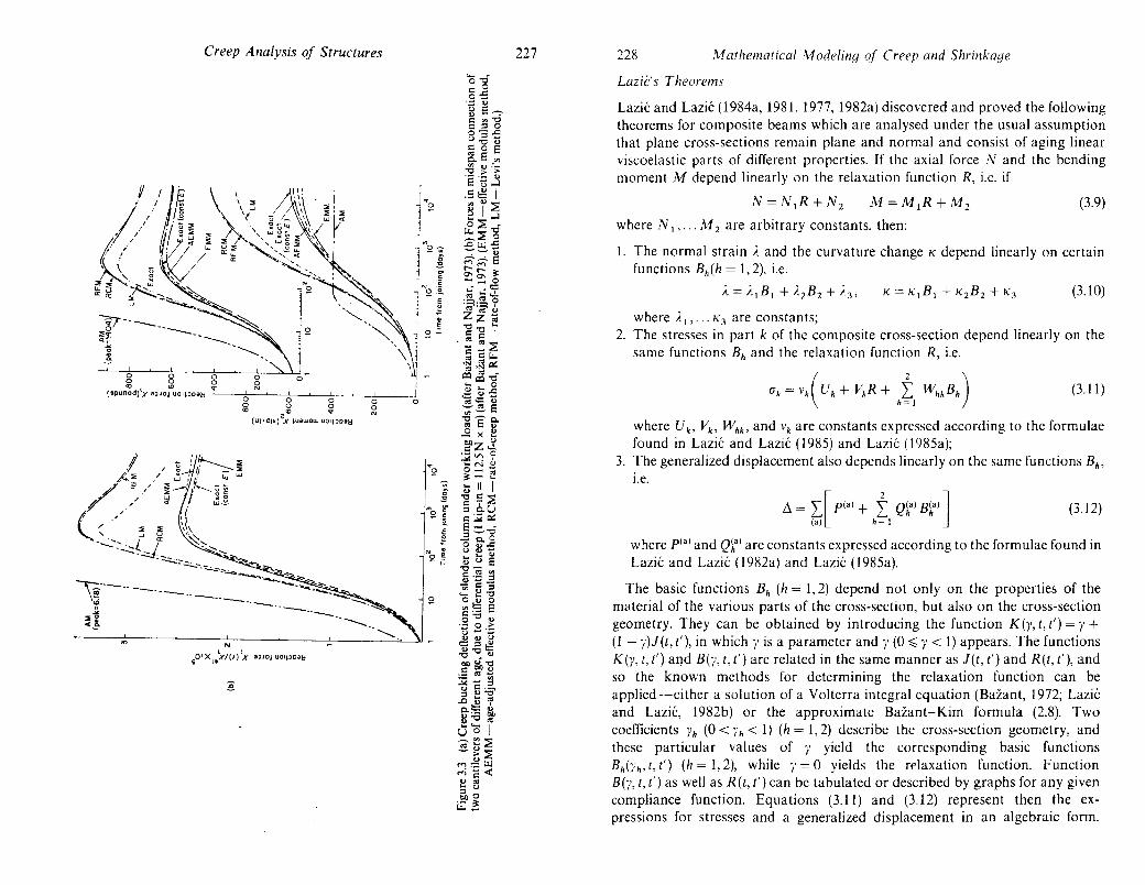
Extensive comparisons of the predictions of the age-adjusted effective modulus method for various structural creep problems with the exact solutions, as well as with the solutions by other approximate methods, were made by Bazant and Najjar (1973). Several of these comparisons are reproduced in Fig. 3.3.
The age-adjusted effective modulus method is at present widely considered to be the most efficient method for linear creep analysis of ageing structures (see for example Dilger, 1982; Neville, et al., 1983; CEB- FIP Manual by Chiorino et aI., 1984; ACI Committee 209 Recommendation, 1982).
c 0
(a) ~
c u ~
0 ~ a:
f-I I (days)
Creep Analysis of Structures 227
N
,.01 x l.'x/(I) LX a:)Jo~ uOlpoaH
22R ]'vf athematical Modeling of Creep and Shrinkage
Lazic's Theorems
Lazic and Lazic (1984a, 198[, 1977, 1982a) discovered and proved the following theorems for composite beams which are analysed under the usual assumption that plane cross-sections remain plane and normal and consist of aging linear viscoelastic parts of different properties. If the axial force N and the bending moment M depend linearly on the relaxation function R, i.e. if
(3.9)
where N I" .. AI2 are arbitrary constants, then:
I. The normal strain ). and the curvature change K depend linearly on certain functions Bh(h = 1,2), i.e.
(3.1 0)
where )'1"" K3 are constants; 2. The stresses in part k of the composite cross-section depend linearly on the
same functions Bh and the relaxation function R, i.e.
(Jk = Vk( Uk + VkR + htl WhkBh) (3.11 )
where U", Vb Whb and \'k are constants expressed according to the formulae found in Lazic and Lazic (1985) and Lazic (1985a);
3. The generalized displacement also depends linearly on the same functions Bh ,
I.e.
L1 = L[p<a) + ± Ql:) B~a)J <a) h = 1
(3.12)
where p<a) and Qha) are constants expressed according to the formulae found in
Lazic and Lazic (1982a) and Lazic (1985a).
The basic functions Bh (h = 1,2) depend not only on the properties of the material of the various parts of the cross-section, but also on the cross-section geometry. They can be obtained by introducing the function K(y, t, t') = y + (1 - ,)l(t,t'), in which,' is a parameter and y (0 ~}' < 1) appears. The functions K (y, t, t') and B(,., t, t') are related in the same manner as 1 (t, t') and R (t, t'), and so the known methods for determining the relaxation function can be applied-either a solution of a Volterra integral equation (Bazant, 1972; Lazic and Lazic, 1982b) or the approximate Bazant-Kim formula (2.8). Two coefficients fh (0 < Yh < 1) (h = 1,2) describe the cross-section geometry, and these particular values of y yield the corresponding basic functions Bh(ih, t, t') (h = 1,2), while }' = 0 yields the r('laxation function. Function B(y, t, t') as well as R(t, t') can be tabulated or described by graphs for any given compliance function. Equations (3.11) and (3.12) represent then the expressions for stresses and a generalized displacement in an algebraic form.

Creep Analysis of Structures 229
Under the assumptions stated in Eq. (3.9), they are accurate when the values of Bh (h = 1,2) and R are calculated through a Volterra integral equation. Lazic and Lazic (1982a) have presented such valus of Band R for the CEB-FIP (1978) compliance function. For limitations where Eq. (3.9) is valid, see Lazic and Lazic (1985). In the special case of a homogeneous cross-section, Lazic's theorem given by Eq. (3.11) reduces to Bazant's theorem.
Improved aging coefficient
In analogy to the aging coefficient X, Lazic and Lazic (1981,1985) defined a new aging coefficient XF for the given composite cross-section. The value of this improved aging coefficient can be determined approximately so that the creep effects at most points of the cross-section are either overestimated or predicted exactly, the exact prediction being imposed for a certain particular cross-section shape often used in practice.
Coefficient XF' in contrast"to the aging coefficient X, introduces the influence of the cross-section geometry. It always has a smaller value than the corresponding aging coefficient x. Thus, the use of X in the analysis of composite cross-sections always leads to some underestimation of the creep effect. In most cases, however, the approximate results obtained by applying the usual age-adjusted effective modulus method with the aging coefficient X to a composite cross-section are very close to the exact linear viscoelastic solution. Nevertheless, for certain forms of the compliance function the deviation from the predictions based on X from the exact solution is appreciable, although still not large. In that case, the use of the coefficient XF offers an improvement, as shown by Lazic to be the case for the CEB-FIP (1978) compliance function. The gain of accuracy from the use of XF instead of X becomes more pronounced if the creep coefficient is larger and if the stress relaxation in the prestressing steel is greater (Lazic and Lazic, 1985). For the ACI compliance function as well as for the BP model, the predictions based on X were shown to be accurate enough (e.g. Bazant and Najjar, 1973). The prevailing opinion seems to be that the use of the usual X is sufficient in most cases, especially in comparison to the errors and uncertainties of J(t, t')-values and of structural creep analysis.
Matrix gt!neralization
The theorem underlying the age-adjusted effective modulus method can be generalized to any structure characterized by a linear relation between column matrix u of generalized displacements and their column matrix f of generalized forces. If the material behaviour is linear, obeying the principle of superposition, this relationship may always be cast in the form
u(t) = I' J (t, t') df(t') = If(t) (3.13) '0
230 lvI athematical i\;fodeling of Creep alld Shrinkage
in which J (t, t') is a square compliance matrix characterizing the components of displacement u at agc t caused by unit applied forces (components off) applied at age t'. This matrix characterizes, in the most general form, the creep properties of the structure. Here J is the square matrix creep operator associated with f. The
inverse relation is
f(t) = I' R(t, t')du(t') = Ru(t) '0
(3.14)
in which R(t, t') is a square relaxation matrix representing the components of forces f at age t caused by unit displacements (components of u) enforced at age t'; and R is the square matrix relaxation operator, characterizing the material creep properties of the structure; ~ = 1- 1 . Note that the underlying operator equations of Lazic's theorem are the special case of these relations.
In similarity to Bazant's theorem, assume that the displacement histories u(t) are linearly dependent on the compliance matrix J (t, to), which is written as
u(t) = a + J(t, to)b
in which a and b are square constant matrices. Theorem (Bazant, 1987). If Eq. (3.15) holds true, then
f(t) = b + R(t, to)a
(3.15)
(3.16)
Proof: Equation (3.15) may be rewritten as u(t) = H(t - t')a + JH(t - to)b. Multiplying all terms of this equation by operator K from the left, we have
Ru(t) = RH(t - to)a + EJH(t - to)b.
Now we may note that
RH(t - to) = R(t, to), Rl=L!b=b,
which proves Eq. (3.16) (I is the identity operator). Similarly to the age-adjusted effective modulus method, Eq. (3.16) can be re
formulated in terms of the increments of u and f from the instant of first loading to, to the current time t. Denoting the initial elastic compliances and stiffnesses of the structure as J(t o, to) = J o, R(t o, to) = Ro, we have
flu=[J(t,to)-JoJb and M=[R(t,to)-RoJa
Expressing the column matrices a and b by matrix inversions from the ~ast two equations, and substituting them into Eqs (3.15) and (3.16) .and th~n mto. the expressions for flu and flf, we obtain the following alge?ralc matrIX rela:lOns between the column matrices of incremental forces and dIsplacements (Bazant,
1987):
M = (Ro - R)[Jo(J - J o) -I flu - uoJ
flu = (J - Jo)[Ro(Ro - R)-I M + foJ
(3.17)
(3.18)

Creep Analysis of Structures 231
These equations represent generalizations of the stress-strain relation of the ageadjusted effective modulus method. Of course, they yield these stress-str;in relations as a special case in which the column matrices f and u are replaced by (J
and e.
As a special case, one can also obtain an algebraic stress-strain relation for the cas.e of general aging linearly viscoelastic material behaviour, for which the POIsson ratio v is not a constant, but variable; v(t, e'). In that case the stress-strain relations may ~e written as ere) = J(f(tl and their inverse as (f(t) = RtU) where J and R a.re matnx operators which are inverse to each other and are expressed o~ the basIs of the matrix compliance function J(t, t') and the matrix relaxation function R( t. t'). The incremental algebraic matrix stress-strain relations are then obtained from Eqs (3.17) and (3.18) by replacing the column matrices M and ~u by ~t and ~(f. The result is (Bazant, 1987):
~E = (J - Jo)[Ro(Ro - R)- 1 ~(f + ~(fo] (3.19)
(3.20)
3.2.5 Methods based on simplified J(t, t') and differential equations
While the algebraic methods just described admit any given compliance function, and make their approximation in the structural analysis phase of the solution, anoth~r group ~f methods solves the structure exactly but simplifies the compliance functIOn to a form that permits an exact structural solution without too much difficulty. So, these methods are based on a certain simplification of the stress-strain relation; they were already discussed in considerable detail in Section 2.2.5. Therefore, we give now only a brief overview with some additional viewpoints.
The rate-of-creep method, also called the Dischinger method, which corresponds to a differential stress-strain relation based on an aging Maxwell model (Eqs 2.84, 2.85), played a historically important role. Next to the effective modulus method, it was the first method to be applied extensively to a multitude of complex structural problems, especially in Europe (while American and British pradi~e favoured the simpler effective modulus method which is certainly not more maccurate). After the introduction of the improvements consisting of the rate-of-flo,,:, method (England and Illston, 1965) or the improved Dischinger method (NIelsen 1970; Rusch et ai., 1973), as well as the age-adjusted effective modulus method, the classical rate-of-creep method became obsolete as a predicti?n ~f mean re.sponse. Nevertheless, aside from providing various Instruc~Ive sImple solutIOns, the method is still useful in that it provides an ~pp:oxImat~ bo~nd on the exact solution. When the stress varies monotonically In time, WhICh IS true of a majority of problems, the rate-of-creep method generally gIves a bound on the exact solution which is opposite to the bound obtained from the classical effective modulus method. Thus, it is still acceptable
232 .'1 aehematical .\1 ode ling of' Creep and Shrinkage
for the designer if he makes his calculations twice, once with the effective modulus method, and once with the rate-of-creep method, and then makes sure that his design is admissible for both solutions. However, using only one of these two methods is inadequate, except when the creep effects are known to be very small.
The improvement of the rate-of-creep method in the form of the rate-of-flow method and its later variant known as the improved Dischinger method (Eq. 2.86) (England and IIlston, 1965; Nielsen, 1970; Rusch et al., 1973) was an important development. At the time of its introduction in 1965, the rate-of-flow method was clearly the best practical method available. However, the ageadjusted effective modulus method discovered subsequently is even more accurate in comparison to the exact solutions according to aging viscoelasticity, and at the same time it is simpler to apply since it consists of an elastic analysis, which is algebraic in time, rather than a solution of differential equations in time. The age-adjusted effective modulus method is the only method used in the ACI 209 Recommendations (1982) (next to the effective modulus) is emphasized as the main approach in the latest CEB Design Manual (Chiorino ct al. 1982), and is recommended in Annexe e (para, e.2) of the CEB-FIP (1978) Model Code, along with the improved Dischinger method as an alternative. For extensive comparisons of various approximate methods with the exact viscoelastic solutions, see Bazant and Najjar (1973) (cf. Section 2.5.5).
Other simplified forms of the compliance function were used in the past for the purpose of facilitating structural analysis. Lcvi and Pizzetti (1951) proposed the first-order differential equation
dl: dO" E dlj; + liu G = d~ + Ij; (3.21)
which may be integrated to yicld
1 'I 1) 1(t,t') = l:.~ + (Ell - i., {l- ;'exp[t!J(t') -1j;(t)J} (3.22)
in which F., Eu are constants, i' = Eul(F. - E..), and !/J(t) = -lnll - </>(t, to),']!}'· A similar method which was popular in eastern Europe was proposed by
Arutyunian (1952). By using a compliance function of the form
lIt, t') = ~ ;--{ 1 + 1j;(1')[1 - exp ( - t - t')J} F: (t ) '1
(3.23)
in which '1 = constant and Ij;(t') = A + Cit' or Ij;(t') = A + Cexp(t'/'1) with constants E and C. the integral-type constitutive law can be reduced to a firstorder differential equation with age-dependent coefficients, which was shown by Bazant (I 966a, b) to correspond to an aging standard-solid rheologic model. On this basis, various structural creep problems can be integrated in time with the help of the incomplete gamma function (Arutyunian. 1952; Bazant, 1965, 1968b). Later, however, it was shown (Bazant and Najjar, 1973) that these solutions

Creep Analysis of Structures 233
deviate greatly from the exact linear viscoelastic solutions when long-time response is considered. It is now clear that, generally, this method is both more complicated and less accurate than the age-adjusted effective modulus method or the improved Dischinger method. The same conclusion applies to Levi's method.
An extension of Arutyunian's method was proposed by Aleksandrovskii (1966). However, his creep function was later shown incapable of a good representation of long-time creep data (BaZant and Thonguthai, 1978).
More recently 10rdaan and England (1977) proposed the use of the Burgers model, which consists of a series coupling of a spring, a dashpot, and a Kelvin unit. He assumed that the effect of aging may be represented by replacing time t with a certain reduced time f) which is a monotonic continuous function of t. Thus, he expressed the compliance function in a non-aging form
1 . J(e - e') = E + f(B - f)') + A {l- exp [ - A(O - f)')]} (3.24)
in which E, A, and ;~ are constants. In terms of variable e, the aging property is removed and structural problems can be solved by Laplace transforms,just as in classical linear viscoelasticity without aging. The comparisons of Eq. (3.24) with test data were limited, and it is doubtful that a close representation can be achieved when test data of very long duration, involving rather different ages at loading, are considered.
Extensions to variable temperature and moisture content were proposed on the basis of replacing time with some reduced time (Sackmann, 1963), In detail, this approach was developed by Mukaddam and Bresler (1972), who also used a certain reduced time to transform the constitutive equation to a non-aging form.
3.2.6 Elastic-viscoelastic analogy for aging materials
The most general aging linearly viscoelastic stress-strain relation can be written as
(3.25)
in which ~ and ~-I are Volterra integral operators. For isotropic properties and a constant Poisson ratio, ~ -I = D!): - I, as stated in Eq. (2.12). These operators obey the same rules as linear algebra, except that a product is not commutative. Thus, any of the equations of elasticity in which only linear combinations of elastic constants appear may be generaliLled to creep by replacing them with the corresponding operators. This correspondence is called the elastic-viscoelastic analogy. It was stated in the operator form for aging materials by Mandel (1958) (see also H uet, 1970), although for the special case of homogeneous structures an equivalent analogy (due to McHenry, see the next section) was presented earlier. (Caution is needed when a product of elastic constants appears; it is then
234 1\1 athematical 1\1 odeling of Creep and Shrinkage
necessary to go over the derivation of the elasticity equation to be converted to creep in order to determine what is the proper order of the operators, since they
are not commutative.) For some illustrations of the use of this analogy, see e.g. Bazant (1975).
3,2.7 Homogeneous structures and McHenry's analogy
Consider a structure that has the following properties: (1) homogeneity, i.e. the creep properties are the same at all points (this excludes, e.g., differences in age or water content); (2) constancy of creep Poisson's ratio v; (3) absence of deformable supports; and (4) linearity of the associated elasticity problem. Further, denote by (Jel(t), uel(t) the stresses and displacements at time t for an elastic structure of timeconstant modulus E, caused by distributed surface loads pit), distributed body forces fit), prescribed boundary displacements UO(t) and prescribed inelastic strains £O(t) as given functions of time. Then: (a) if £0 = 0 and U
O = 0, then
(J(t) = (JeI(t), u(t) = E!; - 1 uel(t) (3.26)
(b) if, instead, p = 0, and f = 0, then
1 (J(t) = E~(J(t), U(l) = Uel(l) (3.27)
For a concise proof. see e.g. Bazant (1975). As an equivalent statement of this analogy, (J(l) and u(t) are equal to the elastic
solution due to the fictitious load E:E - 1 Pill, E~' 1 fit), plus the elastic solution due to the prescribed displacements (I/E}~U(I), and inelastic strains (1/E)~£O(I). In this latter form, the analogy was discovered by McHenry (1943) although for the special case of rate-of-creep method and rcdundant frames (for which the constancy of \' need not be required due to the neglect of shear strains), the essence of this analogy was previously implied in Dischinger's work (1973). A rigorous mathematical proof was given by Arutyunian (1952).
From the foregoing analogy we know that in a homogeneous structure, under the conditions specified above, all the displacements and stresses vary in the same proportion as in a homogeneously stressed specimen.
Applying the principle of superposition, McHenry's analogy can also be used to obtain solutions for homogeneous structures in which the structural system was changed while the structure was under load; see Bazant (1975), in which an
illustrative example is also given.
3.2.8 Conversion of inelastic strains to applied loads
The quasi-elastic stress-strain relations obtained by various types of numerical methods or by the age-adjusted effective modulus method involve inelastic strains known or approximately estimated in advance. In elastic finite element

Creep Analysis of Structures 235
analysis, the effect of such inelastic strains is replaced, according to the principle of virtual work, by equivalent inelastic nodal forces. The use of the following theorem is, however, more general, and is applicable for any method of structural analysis.
Consider a general (anisotropic) elastic stress-strain relation cr·· = Cijkm(ekm - e~m) in which C ijkm are the elastic moduli and e~m is the prescribed inelastic strain tensor. Further define
(3.28)
(3.29)
in which cr;j is the inelastic stress tensor; ]; and Pi' Pi are fictitious volume and surface loads equilibrating a;j; r* is an interface with unit normal nf across which cr?j changes discontinuously from the value cr;j- to the value (17/. Then the stresses, strains, and displacements caused by e;j-are
(3.30)
in which ai/'ij and iii are the solutions corresponding to loads/;, Pi' and N, with no inelastic strains, and to the given boundary displacements, uf, if any.
The special case of this theorem, the proof of which is given in Bazant (1975), is known in thermoelasticity as the body force analogy (Lin, 1968), which is due to Duhamel (1838) and Neumann (1841) for the case of the isotropic tensor eij. For deviatoric plastic strains, this analogy was derived in 1931 by Reissner and, in different contexts, by Eshelby and others (Bazant, 1966a, b, 1967, 1964a). First applications to concrete creep were in the analysis of frames (Bazant, 1964a, 1966a, b), and later in linear and non-linear creep of concrete plates (Bazant, 1967, 1971a, b, 1970, and Lin, 1968).
3.2.9 Variational principles
For aging linearly viscoelastic structures it is possible to formulate variational principles analogous to the principle of minimum potential energy or the minimum complementary energy in elasticity. Such principles may be best obtained according to the elastic-viscoelastic analogy, replacing £ or E- 1 with the corresponding operators. For example, by replacing £-1 in the expression for the elastic complementary energy I1* with the operator (£ -1 d/dlj! + £; 1 )(d/dlj!) - 1 which results from Eq. (2.88) for the rate-of-creep method, it was shown (Bazant, 1961, 1964a, b, 1966a) that for redundant (i.e. statically indeterminate) structures:
(3.31 )
This was called the principle of minimum deformation resistance; P k = concentrated loads (k '= 1,2, ... 11), I\'k = load-point displacements, and V = vol ume of the
236 A1athematical Modeling of Creep and Shrinkage
structure. This principle, which implies the compatibility conditions, was show to vield the differential equations for the redundants Xk in a statically indeterminate system. The deformation rates are obtained as dwk/dlj! = 8fP/8Pk and the compatibility conditions are cfP/cX k = ° (stresses cr depend linearly on Xk
according to equilibrium conditions). The principle of minimum deformation resistance in Eq. (3.31) is also applicable for the CEB-FIP improved Dischinger method if 1/ E(t) is replaced with I! E(t') + 1 /E~[, according to Eq. (2.86). A similar principle for the rate-of-creep method was later expounded by England and coworkers (e.g. Zeitouni and England, 1987).
Although the principles such as Eq. (3.31) are theoretically interesting, they do not seem t9.- provide new essential information since solutions can be obtained without them in other ways, e.g. directly from the elastic-viscoelastic analogy on the basis of the variational principles of elasticity. In incremental numerical solutions, which reduce the creep problem to a sequence of elasticity problems, again only elastic variational principles are needed.
It may be pointed out that for non-linear creep of concrete at high stress, there exist no variational principles analogous to the lower and upper bound theorems
of plasticity.
3.3 NON-LINEAR METHODS
In contrast to metals and clays, and in similarity to many polymers, concrete creep may be considered to be approximately linear for many types of response in the service stress range. Significant non-linearities nevertheless exist. In the high stress range, concrete creep is highly non-linear. Although the understanding of non-linear methods for concrete creep is much more limited than it is for the linear methods, some noteworthy advances have been made and will now be
briefly reviewed.
3.3.1 Non-linearity due to humidity and temperature variation
This is the main source of non-linearity under constant loads in the service stress
range. I ts source is twofold:
1. The cross coupling of creep with shrinkage or thermal expansion, which causes that these strains are not additive and need to be taken into account in the form of, for example, stress-induced shrinkage (or swelling) and stressinduced thermal expansion (or contraction).
2. Cracking or tensile strain softening, which inevitably accompanies the changes of environmental humidity and temperature and is caused by the delay due to diffusion (see Sections 2.3.3-2.3.5).
These effects may be analysed numerically in a step-by-step fashion, with iterations in each time step. This technique was employed, e.g. by Bazant and Wu

Creep Analysis of Structures 237
(1974), Becker and Bresler (1977), Iding and Bresler (1982), Wittmann and Roelfstra (19g I), and Jonasson (1977). A rather simple analysis of these effects for nuclear reactor containments was made by Bazant et af. (1975), who employed the age-adjusted effective modulus method, introducing corrections to the effective modulus on the basis of approximate drying histories of the layers throughout the shell thickness.
3.3.2 Non-linearity due to cracking or strain-softening
These effects are normally taken into account in step-by-step time integration by adjusting the incremental stiffness according to the stress and strain values in the previous iteration of the same step or, for the first iteration, in the last iteration of the previous step. There are, nevertheless, serious problems with convergence of the iterations, as well as with convergence when the structural discretization is refined. These problems are due to strain-localization instabilities and border on fracture mechanics. A vast amount of research is being done in this field (for a review see, e.g. Bazant, 1986), most of it not motivated by concrete creep and shrinkage but still applicable to it.
A particular difficulty arises with strain-softening when the time steps are decreased substantially beyond the shortest relaxation time, as is necessary when long-time creep is analysed. It was found (Bazant and Chern, 1985) that an arbitrary increase of the time step is made possible by an exponential algorithm which is analogous to the exponential algorithm for the Maxwell chain model and is based on an exact solution of the incremental stress-strain relation for a strain-softening element under the assumption that the coefficients of the associated differential equation are constant.
3.3.3 Non-linearity due to cyclic loading
Even in the linear service stress range, a cyclic stress component superimposed on a constant stress produces after many repetitions a significant increase of deformation, a phenomenon often referred to as the cyclic creep and sometimes considered an aspect of fatigue. The increase of the deformation due to stress cycling depends on the stress non-linearly, and so the phenomenon is not covered by linear constitutive laws (see Section 2.4.2). This type of deformation is probably caused by progressive formation and irreversible openings of microcracks.
In cyclic creep we are usually interested in a large number of repetitions, at least 1000 and even over 106
. Thus it is impossible to follow the stress history in a stepby-step calculation. A simple way to calculate the effect of cyclic creep is again to adjust the effective modulus Eer (or En) on the basis of the cyclic creep deformation predicted for the stress history which would take place if there were no redistributions of stress in the structure due to cyclic creep. After solving the
238 Mathematical Modeling of Creep and Shrinkage
structural problem with such modified effective modulus values, which are generally different for each point of the structure, the calculation can be iteratively repeated updating the magnitude of the cyclic creep on the basis of the stress history with stress redistributions obtained in the previous iteration. As an· approximation, only one long step from the time of first loading to the final time after many cycles is considered. This approach was used by Bazant (1968a) in the analysis of cyclic creep effect in long-span prestressed concrete bridges.
3.3.4 Non-linearity at unloading and adaptation
In concrete, significant deviations from linearity (i.e. from the principle of superposition) are observed at decreasing strain, especially at large sudden unloading (see Section 2.4). Generally, the unloading deformation behaviour is stiffer than that predicted according to linearity. The deviations from linearity are not caused by the decrease of stress, since stress relaxation follows the predictions of linear analysis, but by a decrease of strain. There are some stress-strain relations (e.g. the rate of flow and improved Dischinger methods) which are calibrated according to the behaviour at unloading, but then they sacrifice the possibility of good representation of test data at constant stress for a wide range of ages at loading and for long durations. In these approaches, one cannot of course speak of non-linearity at unloading.
The non-linearity which is responsible for the reduced recoverability of strain at unloading has been called the adaptation. Described by an adaptation parameter in the kernel of the iterative integral (Bazant and Kim, 1979a), this non-linearity also causes an increased stiffness for load increments after a longer period under sustained compressive load. It appears that sustained compressive stress gradually stiffens concrete, perhaps promoting creation of bonds as in hydration. On the other hand, tensile stress should cause a decrease of stiffness, although experimental data to verify this are still lacking.
For the integral-type constitutive law with a kernel that includes a stressdependent adaptation parameter, the structural creep analysis can be again carried out in a step-by-step manner, with iterations in each time step in which the value of the adaptation parameter is updated from one iteration to the next until a certain tolerance is met (Bazant and Kim, 1979a; Bazant et al., 1982). The integraltype formulation would of course be inefficient for large structures, and for that purpose it would be preferable to develop a rate-type form of the constitutive equation with a stress-dependent adaptation parameter. Remark. An efficient description of the adaptation non-linearity is possible with the model in the Addendum to Chapter 2).
3.3.5 Non-linearity at high stress and multiaxial viscoplasticity
Modelling of this non-linearity is important for an accurate determination of the safety of a structure against collapse under a long-time load, especially when
Creep Analysis af Structures 239
lo.ng-time. bu~kling is inv~lved. The uniaxial formulation of this non-linearity, wIth applIcatIOns to long-time stability of columns, has been the most researched type of non-linearity in creep of concrete. Most of the previous studies have used a no~-linear generalization of the rate-of-creep method (Dischinger method), ~hlch. correspo?ds to t~e Maxwell rheologic model with stress-dependent VISCOSIty, modelmg b~h~vlOur that i.s generally termed viscoplasticity. Although the .M~xwell .model IS madequate m the service stress range, it appears more r.ealIStiC for high stresses near collapse. This is no doubt due to a transition from lmear aging viscoelasticity to a plastic type of response as the stress is increased from the service stress range to the failure range.
Various types of the constitutive law based on the aging Maxwell model with stress-dependent viscosity were used in uniaxial analyses of column buckling by Manuel and McGregor (1967), Bazant and Tsubaki (1980), Mauch and Holley (1963), and others. Although some approximate analytical solutions were attempted in the early work, the recent more realistic analyses of non-linear column buckling utilized step-by-step integration in time, with iterations in each step. This algorithm appears to converge, although near the collapse load the convergence is, of course, slow (partly because the creep problem must be solved under load rather than displacement control). ~or the p~rpose of finite element modeling of nuclear vessels subjected to
aCCidental high-temperature loads, some triaxial forms of the non-linear creep law of concrete have been recently developed by Marchertas and Kennedy (1983). I: seems reasonable to assume that this triaxial formulation should represent a time-dependent viscous analogy to a triaxial plasticity-type model for the nonlinear d~forrn~tions of concrete. Such a generalization can be obtained if the plastic proportIOnalIty parameter used in a plasticity model is replaced with a stressdepe~~ent viscosity, while discarding the continuity condition of the theory of plasticity based on the subsequent loading surfaces which formulate the hardening-softening. rule. These formulations have been coded in finite elements using step-by-step integration in time, with iterations in each step. Reasonabl~ agreement with some limited test data for high-temperature behaviour was demonstrated; however, a much more extensive experimental verification as well as theoretical development will probably be needed in the future.
3.4 EFFECTS IN AGING LINEARLY VISCOELASTIC STRUCTURES
Aging linearly viscoelastic material behaviour gives rise to a variety of effects in struct.ur~s, which are by now quite well understood and easier to analyse than the non-lInear effects. We will now briefly review the current knowledge of these effects.
3.4.1 Relaxation and shrinkage stresses
Relaxation of a st.ruclure is the stress or internal force variation induced by a sudden enforced displacement or inelastic strain such as thermal expansion. If the
240 Mathematical .Wadeling af Creep and Shrinkage
structure is homogeneous, i.e. its creep properties are the same at every point, all the stresses in the structure vary in proportion, a property which follows from McHenry's analogy (Section 3.2.7). For a non-homogeneous structure, other effects are superimposed and the stress variations at various points of the structure are not proportional. However, the stress variation obtained from the assumption of approximate homogeneity usually dominates.
For a homogeneous structure, it suffices to obtain the elastic stresses (or internal forces) caused by the enforced displacements, and then reduce them in proportion to the relaxation function R(t, t'). According to the age-adjusted effective modulus method,
O'(t) = E(to)R(t to) = 1 _. cf>(t, to) O'(to) , 1 + X(t, to)cf>(t, to)
(3.32)
in which to is the age at imposed deformation. However, direct use of R(t, to) may be preferable here, since X is derived from R(t, to).
When shrinkage deformations are inhibited by the constraints of a redundant structure, the deformations are imposed gradually rather than suddenly. Again, if the structure is homogeneous the solution may be easily obtained from McHenry's analogy. In general, this leads to the integration of a Volterra's integral equation, easily carried out in a step-by-step manner. It is found, however, that relatively good results are obtained if the evolution of shrinkage strain is assumed to be proportional to the creep coefficient cf>(t, to), in which case the age-adjusted effective modulus method may be applied. This yields for the internal shrinkage forces the formula
X(t) = ~_X;hCSh(~L_ (3.33) 1 + X(t, to)cf>(t, to)
in which X;h = elastic shrinkage force corresponding to unit shrinkage, and Esh (t) = shrinkage strain at age t.
It must be emphasized that this formula should be applied only for the crosssection resultants (axial force or bending moment) and not for the stresses at various points. This is because the applicability of this formula to stresses would require the shrinkage strain csh(t) to be the same not only for all the cross-sections of the structure, in the mean, but also for all the points of each cross-section, which is, of course, not true due to the shrinkage delay from moisture diffusion. As previously discussed (Sections 2.3 and 3.3.1), the actual shrinkage stress values at individual points differ greatly from the values obtained from Eq. (3.33) according to the formulae of the theory of bending.
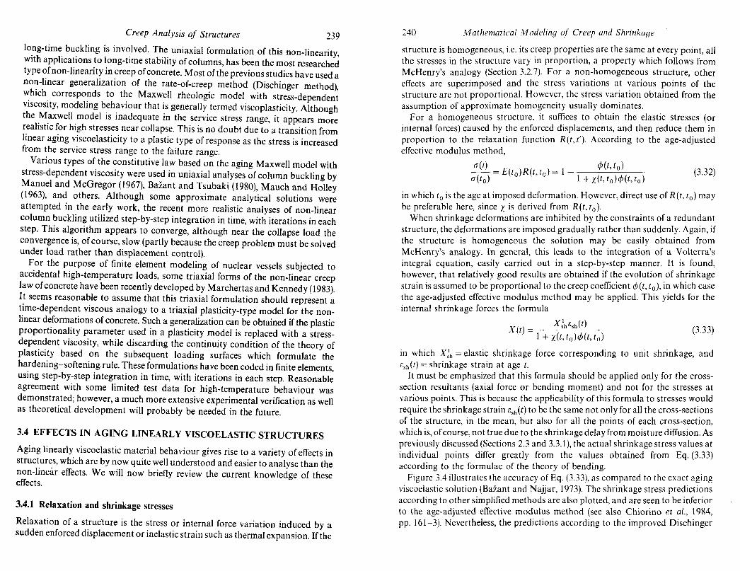
Figure 3.4 illustrates the accuracy of Eq. (3.33), as compared to the exact aging viscoelastic solution (Bazant and Najjar, 1973). The shrinkage stress predictions according to other simplified methods are also plotted, and are seen to be inferior to the age-adjusted effective modulus method (see also Chiorino et aI., 1984, pp. 161-3). Nevertheless, the predictions according to the improved Dischinger

1 -
3
.- 2 III
"<ta.
'0 G
.....
b 1
1
Creep Analysis of Structures
10
, ,ReM I
I
t- to (days)
-----
AEMM
Figure 3.4 Shrinkage stresses
241
method (CEB-FIP Model Code, 1978), which require solution of a differential equation, are still quite good. Ki'istek et al. (1982) obtained another simple solution assuming that the delayed elastic response is linear in the load duration (however, they demonstrated superiority only to the rate-of-creep method).
3.4.2 Composite and inhomogeneous cross~sections of beams
In a cross-section in which the creep properties ofthe material are not the same at all the points, creep causes stress redistributions. Further time-dependent stress variations are caused when the cross-section is built in stages and some parts carry load before the remaining parts are cast or attached.
The exact analysis of a composite or inhomogeneous cross-section according to aging linear viscoelasticity leads to a system of two Volterra integral equations if the cross-section resultants (axial force and bending moment) are known. Applying the operator formulation, Huet (1970) adopted this approach and formulated (in 1973-75) the general solution in a powerful matrix operator form. A general solution was given by Bazant (1971), and in the operator form by
242 Mathematical Modeling of Creep and Shrinkage
Lazii; and Lazii; (1977, 1984b), and also, in terms of the so-called reduced relaxation functions, by Mola (1982a, b).
In today's climate, however, it is easy to obtain an accurate solution with a computer by step-by-step methods; e.g., Bazant (1962, 1966b, Bazant and Najjar (1973) 1973, 1975); Neville et al. (1983); Chiorino et at. (1984). For a simple approximate solution, it is usually sufficient to apply the method of the aging coefficient, x, although with certain types of compliance function an appreciably improved accuracy may be obtained by the method of the improved aging coefficient, XF (Lazii; and Lazie, 1981, 1985; Lazii;, 1982).
Wh.en the structure is redundant, the cross-section resultants are normally not known. The exact analysis leads to the system of Volterra integral equations coupled with a differential equation of the beam, which was solved directly by Bazant (1970). This can also be reduced to a system of Volterra integral equations which contain no unknown functions, only the redundant forces. By solving this system, one obtains the cross-section resultants, and then the above-mentioned method of cross-section analysis should be applied. This method is complicated, although the exact solutions for redundant composite structures can be obtained for the rate-of-creep method (Lazii; and Lazii;, 1982b), as well as for non-aging elasticity (Lazii;, 1975). An accurate numerical solution can be carried out more easily by using the incremental quasi-elastic form of the stress-strain relation for the time steps, which leads to a series of linear elasticity problems for an elastic redundant structure with composite cross-sections (e.g., Bazant, 1964a, b, 1970, Huet, 1980). Again, however, exact solutions are usually not needed for practice because the age-adjusted effective modulus method was shown to be quite accurate for these problems (see the comparison in Fig. 3.5).
The method of the improved aging coefficient XF as well as Lazie's theorems can be utilized, too. In Lazit (1982), the general case was treated by using the improved aging coefficient with practical applications in various structural creep problems. Under the assumption that the redundant forces depend on the relaxation function linearly, LaziC's theorems lead to a system of algebraic equations for the redundant forces (Lazit, 1985a). This method was shown to be quite accurate compared to the exact viscoelastic solutions.
The solution of the composite cross-section is analogous to its elastic analysis for arbitrary initial strains. As an extension of the creep solutions according to incremental laws (see Chapter 2), as well as the solution by the Trost method (1967), and an early special approximate version of the age-adjusted effective modulus method, the general case was treated by using the age-adjusted effective modulus method by Bazant and Najjar (1973). More recently, Dilger (1982) and Neville, Dilger and Brooks (1983) appraised this approach as the most powerful one and demonstrated practical applications in various situations. We will now briefly outline this approach.
Consider a reinforced uncracked concrete cross-section with a single layer of steel. It is convenient to introduce a transformed cross-section characterized by

2 .1 L...-...L.-L....L...L..U..Lll----'--'-, " ,," " ""I
3.1
~ 2.9 ~ -I/)
<I> Q; .... u ~ 2.7 u )( a 2
10 102
103
f-fO(days)
! , II. "I
Figure 3.5 Chan~es of stresses and girder moment due to creep in steelconcrete composite beam (100 psi = 0.6895 N/mm2; 106 in x I b ~
112.5 kN x m) to = 7 days (after Bazant and Naijar, 1973) .
244 Mathematical Modeling or Creep and Shrinkage
the creep moduli ratio n* = Es;E~(t, tol = no[l + X(t, to)¢(t, to)] (3.34)
in which Es = elastic modulus of steel, and no = EsiEc = elastic moduli ratio based on the standard concrete modulus Ec at age 28 days. The calculation consists of two stages (Sattler, 1950; Bazant, 1962, 1966a, 1975; Dilger, 1982). First, unrestrained creep and free shrinkage is allowed to take place in each part of the cross-section. Elastic stresses which cancel these deformations are then calculated on the basis of transformed cross-section properties, and their resultants over the entire cross-section, consisting of axial force N* and bending moment M*, are evaluated. Subsequently, these resultants are applied in the opposite (negative) sense to the transformed composite cross-section and the stresses produced by this loading are then superimposed. If the structure is redundant (Bazant and Najjar, 1973), one must first calculate the structural loads which are in equilibrium with the cross-section forces - M* and - N*, and then superimpose the effect of these loads calculated for the redundant elastic structure with the transformed elastic composite cross-sections. When the steel in the cross-section is prestressed, one must include the prestress in the cross-section resultants M* and N*.
The aforementioned procedure can also be applied to composite sections made of concretes with different properties or different ages, although the error of the age-adjusted effective modulus might not be so small in this case (Chiorino, 1984, p. 266). Instructive examples were given by Chiorino (1984, pp. 208-17) and a general solution was presented in Bazant (1962, 1966a) and in Huet's works during 1975-80 (Huet, 1978, 1980).
It should be noted that the composite action of the cross-section alters the stress relaxation in prestressing steel, compared to a solution of the so-called intrinsic relaxation, i.e. the stress decrease in steel calculated without taking the composite action into account. A correction factor C(r which multiplies the intrinsic relaxation in ordcr to obtain the correct stress relaxation in steel in a composite cross-section was calculated in a step-by-step procedure by Tadros et al. (1977a, 1979) and was given in a chart form by Dilger (1982).
The aforementioned calculation procedure for composite cross-sections can also be used for an approximate linear treatment of the differences in creep and shrinkage caused by drying or temperature change in the cross-section (Bazant et al., 1975). It may also be adapted to analyse the effect of cracking or strainsoftening in certain parts of the cross-section, occurring simultaneously with creep (Kfistek and Bazant, 1987).
To illustrate the foregoing cross-section analysis with the age-adjusted effective modulus method, the formula for the loss of compression force in a thin slab of a steel-concrete composite statically determinate beam may be given:
( _ ¢(t,to)Nc(to) + dGsh(t)Ec(to)Ac
!:iNc t) - -1 )~) / ( 2 ) +X(t,to 'I'(t,to + Ac,nAs l+e As/Is (3.35)
in which As and Is = area and central moment of inertia of the steel girder, e =

Creep Analysis of Structures 245
eccentricity of the thin slab centroid with respect to the steel girder centroid, n = Esl Ec(to), Ac = area of the concrete slab (whose centroidal moment of inertia I is assumed neglig~ble). The moment .chang~ in the steel girder then equals eNc(t)~ The creep deflectIOn of the composIte statIcally determinate girder can then be computed from the moment in the steel girder.
An e~ually .simple ~ormul~ is possible for the prestress loss in a statically determInate gIrder wIth a sIngle tendon. In this case, however, the gain of accuracy compared with the classical effective modulus method is relatively small.
3.4.3 Inhomogeneous redundant beam structures
When a beam structure consists of parts that have significantly different ages, stress redistributions occur due to creep. Other types of structural inhomogeneity, which can be analysed linearly as a good approximation, are differences in the cross-section size or in the degree of drying along the structure. Overall, the stresses in an inhomogeneous structure are transferred due to creep from the parts which creep more into the parts which creep less.
The age differences, which typically arise in segmental construction of box girder bridges, were initially analysed on the basis of the rate-of-creep method (see e.g. Finsterwalder and Knittel, 1955; Bazant, 1961), in which case the problem was reduced to a system of first-order differential equations for the redundants. How~ver, as demonstrated later (Bazant and Najjar, 1973), the age-adjusted effec~lve mod~lus method is both more accurate and simpler, consisting of an elastIc analysIs of a frame structure with a non-uniform elastic modulus.
A simple illustrative example is the shear force produced at midspan of a fixedend beam consisting of two identical cantilevers which are of equal length and are connected at midspan by a hinge. This force, X, is obtained by solving the following compatibility equation based on the age-adjusted effective modulus method:
{[I + X(t, to)</>(t, to)]fa + [1 + X(t - ~, to )</>(t - ~, to )Jfb} X(t)
+ [¢(t, to) - </>(tl' to)] (ja + [</>(t -~, to) - ¢(t l -~, to)](jb = 0 (3.36)
in ~hich fa, fb are the unit flexibilities of the left and right cantilever, (ja and (jb are theIr dellections due to applied loads, and ~ = age difference (the left cantilever is older). Each cantilever is assumed to be of uniform age and to be loaded when its age. is to; t 1 is the age of the older cantilever when the two cantilevers are joined by a hmge at the midspan. For a detailed exposition, see, e.g. Bazant and Najjar (1973), Bazant (1975), Chiorino et al. (1984).
In the foregoing type of problem, the stresses in the older cantilever are constant from time to to time t l , after which they vary gradually. This type of stress variation is not linea'r in the creep coefficient </>(t, to), as is assumed in the age-adjusted effective modulus method, and therefore the error of this method is
246 Mathematical Modeling of Creep and Shrinkage
larger. A certain useful correction for this type of stress history was formulated by Kfistek et al. (1982).
3.4.4 Steel-concrete systems (cable-stayed bridges)
A beam or frame in which concrete members interact with steel members is a special case of an inhomogeneous structure, in which one part of the structure exhibits creep, the other does not. The most important structures of this type are perhaps the cable-stayed bridges with a concrete girder. Due to creep in the girder, the internal forces are gradually transferred from the concrete beam into the cable stays, which causes the forces in the cables to grow in time. A special case occurs when the initial cable forces are such that the initial deflections of the girder at the cable support points are zero. In that case there the cable forces vary only due to axial creep shortening and shrinkage of the girder, but not due to bending creep of the girder (provided that homogeneous linearly viscoelastic material properties are assumed). Again, analysis according to the age-adjusted effective modulus method is relatively simple. Also pertinent is a general solution of redundant homogeneous structures with elastic members presented by Chiorino et al. (1986), based on the works of Mola (1979, 1981, 1982a, b) on reduced relaxation functions.
3.4.5 Change of structural system
A change of the structural system is often involved in the construction procedure ofa modern prestressed concrete structure and has been analysed in many works; see e.g. Bazant (1962, 1964a, b, 1966a, 1975), Bazant and Najjar (1973), Neville et al. (1983), Chiorino et at. (1984), Chiorino and Mola (1982) (restraints introduced at various times), Chiorino et al. (1986) (delayed elastic restraints), etc. For instance, bridge spans are cast initially as simply-supported beams, and later, while these beams already carry its dead load, they are connected above the supports. If they were not connected, the simply-supported beams would continue deflecting due to creep and the relative rotations ofthe beams above the supports would gradually grow. However, the growth of the relative rotations is restrained after the simply-supported beams are connected. This is equivalent to enforcing on the simply-supported beams an opposite rotation above the midspan, causing a negative bending moment which gradually builds up at the midspan location (Fig. 3.6a).
Another typical example comes from cantilever construction of prestressed concrete bridges. The two halves of the bridge span are initially built as cantilevers and later, while they already carry the dead load, they are connected at midspan. This prevents further growth of relative rotations and relative deflections of the two cantilevers at their ends, thus causing a gradual build-up of a positive bending moment at the midspan. If the creep in the two connected cantilevers is not the same, for example due to differences in age, then a shear force

Creep Analysis of Structures 247 (0) (b)
I k M '0
& 4 IT k
'1 ~ ~ ~
(c)
llf Ti t X(t)
I
W (d) =AW o L~ I
1--===-----~Xll)
t '0 'I
J~ I ~~. '0 '1
Figure 3.6 Examples of changes in the structural system
also gradually builds up at the midspan. Creep and shrinkage effects considering the load histories from a sequence of construction phases for a prestressed concrete bridge were analysed by Haas (1982) (Fig. 3.6b).
If a hinge is used at midspan in order to avoid the positive bending moment, then a shear force gradually builds up after the instant of joining if the two cantilevers are of different ages. This is normally the case in segmental construction where the same traveller truss is used for casting or assembly of the bridge segments. The use of a hinge at midspan, however, is not a good design practice because deflections are considerably larger than for a span with a monolithic connection at midspan. A change of slope at midspan, which is likely to develop due to the random nature of creep, creates serious serviceability problems.
248 "'v1athematical Modeling of Creep and Shrinkage
Another example, also from segmental bridge construction, is the procedure in which the end span is built as a cantilever from the pier towards the abutment. Subsequently, a bearing is inserted between the end of the cantilever and the abutment. If it were not inserted, the cantilever end would continue deflecting, and since this is prevented by the bearing, a vertical reaction gradually builds up at the abutment (Fig. 3.6(c)).
Examples of changes in the structural system are not limited to bridge construction. We may cite for example shored construction of slab buildings, in which the shores are removed, then replaced by reshores, which are later removed again (Aguinaga-Zapata and Bazant, 1986).
Let UeJ be the displacement or rotation of the structure in the sense of the later imposed constraint, evaluated for the initial structural system I. Let to be the age of concrete at load application, and t I the age at the time of adding the constraint. The displacement which would take place in the sense of the constraint if the constraint were not added is Uel [cf>(t, to) - cf> (t I, to)]. We can consider this displacement to be imposed on the structure in the opposite sense. The stresses produced by this gradually increasing displacement are reduced due to creep by the factor 1 + X(t, t I). From this type of consideration, one can conclude that generally an internal force or stress in a redundant structure after a change of structural system is expressed as (Bazant, 1975; Kfistek and Bazant, 1987):
XU) = Xl + (XII _ XI) cf>(t, to) - cf>(t l , to) (3.37) 1 + x(t,tdcf>(t,t l )
in which Xl and XII are the values of the internal force calculated for an elastic structure with structural system lor II respectively. The long-time deflection due to creep, u(t), after the structural system I is changed into the structural system II at time t I may be calculated as
u(t) = ulcf>(t, to) + (u ll- ul)[cf>(t, to) - cf>(t, tdJ (3.38)
where ul, uII = elastic deflections corresponding to structural systems I and II,
respectively. The first term represents the usual creep deflection without the effect of the change of structural system, and the second term is the creep deflection due to the change of structural system at time tdtl ~ to).
Compared to the exact aging viscoelastic solution, the foregoing formula (Eq. 3.37) is very accurate if the time-lag t I - to is small. If it is large, then the evolution of displacement
u(t) = uIcf>(t, to) + (uII - ul)[cf>(t, to) - cf>(t l , to)J
differs more substantially from the curve of cf>(t, to), which means that the assumptions of Bazant's theorem are becoming less realistic, as is illustrated with the typical stress history shown in Fig. 3.6(d). However, a correction may be introduced in a two-step analysis in which the time at which the structural system is changed is adjusted on the basis of a preliminary analysis of stress relaxation, which was done by Kfistek et al. (1982).
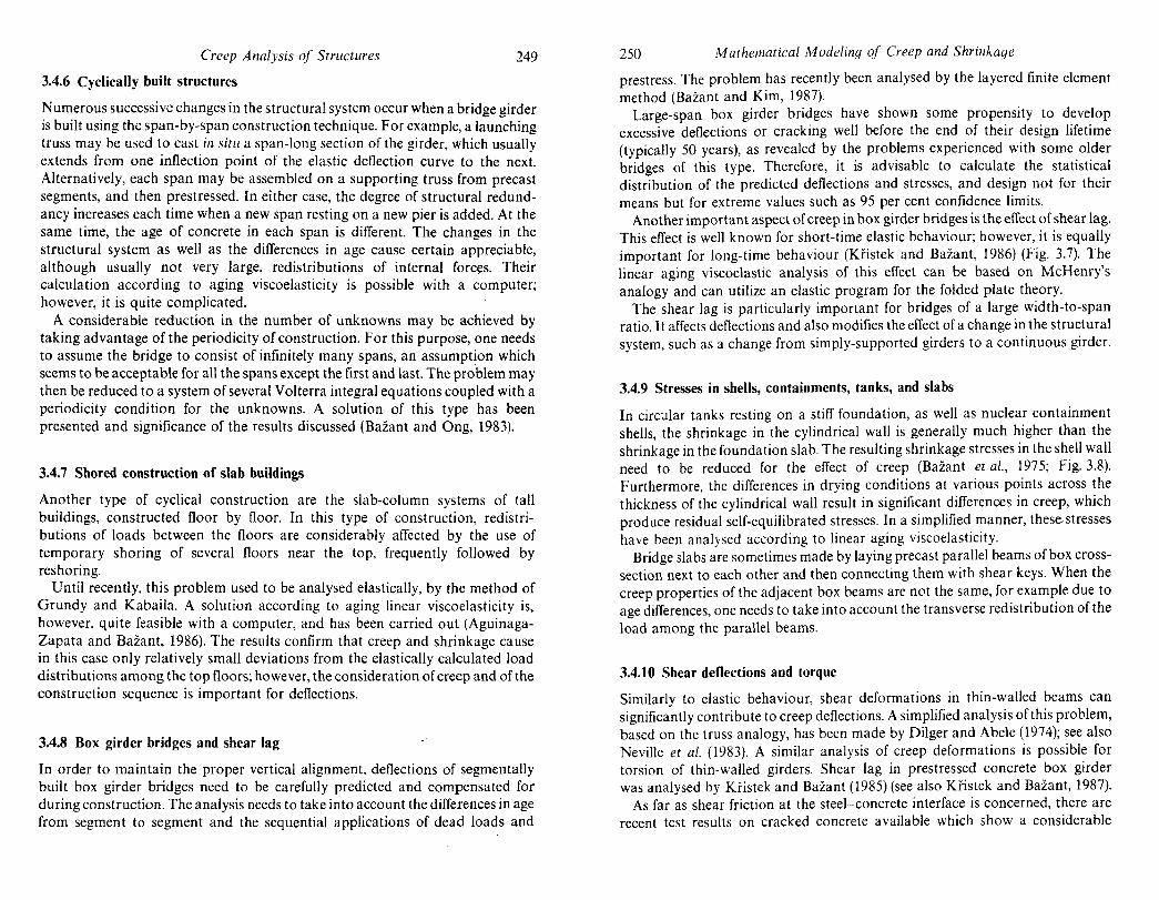
Creep Analysis of Structures
3.4.6 Cyclically built structures
249
Numerous successive changes in the structural system occur when a bridge girder is built using the span-by-span construction technique. For example, a launching truss may be used to cast in situ a span-long section of the girder, which usually extends from one inflection point of the elastic deflection curve to the next. Alternatively, each span may be assembled on a supporting truss from precast segments, and then prestressed. In either case, the degree of structural redundancy increases each time when a new span resting on a new pier is added. At the same time, the age of concrete in each span is different. The changes in the structural system as well as the differences in age cause certain appreciable, although usually not very large, redistributions of internal forces. Their calculation according to aging viscoelasticity is possible with a computer; however, it is quite complicated.
A considerable reduction in the number of unknowns may be achieved by taking advantage of the periodicity of construction. For this purpose, one needs to assume the bridge to consist of infinitely many spans, an assumption which seems to be acceptable for all the spans except the first and last. The problem may then be reduced to a system of several Volterra integral equations coupled with a periodicity condition for the unknowns. A solution of this type has been presented and significance of the results discussed (Bazant and Ong; 1983).
3.4.7 Shored construction of slab buildings
Another type of cyclical construction are the slab-column systems of tall buildings, constructed floor by floor. In this type of construction, redistributions of loads between the floors are considerably affected by the use of temporary shoring of several floors near the top, frequently followed by reshoring.
Until recently, this problem used to be analysed elastically, by the method of Grundy and Kabaila. A solution according to aging linear viscoelasticity is, however, quite feasible with a computer, and has been carried out (AguinagaZapata and Bazant, 1986). The results confirm that creep and shrinkage cause in this case only relatively small deviations from the elastically calculated load distributions among the top floors; however, the consideration of creep and of the construction sequence is important for deflections.
3.4.8 Box girder bridges and shear lag
In order to maintain the proper vertical alignment, deflections of segmentally built box girder bridges need to be carefully predicted and compensated for during construction. The analysis needs to take into account the differences in age from segment to segment and the sequential applications of dead loads and
250 Mathematical Modeling of Creep and Shrinkage
prestress. The problem has recently been analysed by the layered finite element method (BaZant and Kim, 1987).
Large-span box girder bridges have shown some propensity to develop excessive deflections or cracking well before the end of their design lifetime (typically 50 years), as revealed by the problems experienced with some older bridges of this type. Therefore, it is advisable to calculate the statistical distribution of the predicted deflections and stresses, and design not for their means but for extreme values such as 95 per cent confidence limits.
Another important aspect of creep in box girder bridges is the effect of shear lag. This effect is well known for short-time elastic behaviour; however, it is equally important for long-time behaviour (Kfistek and Bazant, 1986) (Fig. 3.7). The linear aging viscoelastic analysis of this effect can be based on McHenry's analogy and can utilize an elastic program for the folded plate theory.
The shear lag is particularly important for bridges of a large width-to-span ratio. It affects deflections and also modifies the effect of a change in the structural system, such as a change from simply-supported girders to a continuous girder.
3.4.9 Stresses in shells, containments, tanks, and slabs
In circ:.llar tanks resting on a stiff foundation, as well as nuclear containment shells, the shrinkage in the cylindrical wall is generally much higher than the shrinkage in the foundation slab. The resulting shrinkage stresses in the shell wall need to be reduced for the effect of creep (Bazant et al., 1975; Fig. 3.8). Furthermore, the differences in drying conditions at various points across the thickness of the cylindrical wall result in significant differences in creep, which produce residual self-equilibrated stresses. In a simplified manner, these. stresses have been analysed according to linear aging viscoelasticity.
Bridge slabs are sometimes made by laying precast parallel beams of box crosssection next to each other and then connecting them with shear keys. When the creep properties of the adjacent box beams are not the same, for example due to age differences, one needs to take into account the transverse redistribution of the load among the parallel beams.
3.4.10 Shear deflections and torque
Similarly to elastic behaviour, shear deformations in thin-walled beams can significantly contribute to creep deflections. A simplified analysis of this problem, based on the truss analogy, has been made by Dilger and Abele (1974); see also Neville et al. (1983). A similar analysis of creep deformations is possible for torsion of thin-walled girders. Shear lag in prestressed concrete box girder was analysed by Ki'istek and Bazant (1985) (see also Kfistek and Bazant, 1987).
As far as shear friction at the steel-concrete interface is concerned, there are recent test results on cracked concrete available which show a considerable

Creep Analysis of Structures
(0)
2 I -\
7 2 -\
(b)
1!!!!!!!!!!!!!!!!!!!!!!!'!'!""!!'!!!!"'!!'!!!!!!!!!!"!!!!!!!!!!"'!!"""!!!!""l
I· t = 25m
(c)
kN/m2 15
1 10
5
o
-I. t= 25m
251
Figure 3. 7 Effect of creep on a box girder bridge (Kfistek and Bazant, \985). (a) Cross-sectional dimension; (b) longitudinal configuration; (c) longitudinal normal stresses, mean ± standard devi
ation; (d) deflections, mean ± standard deviation
increase of the shear di$placement and crack opening during constant shear stress (Frenay, 1985). The relations among the shear stress, normal stress (or normal confining stiffness), shear displacement, and crack opening depend on the shear reinforcement ratio, the mix of concrete, and the logarithm of loading duration. Although stresses and displacements are related non-linearly, those relations can be approximated by an average relation for design purposes. Without further
-~...;J-- 70ft---~
(a)
117128ft (0)
I
37 ft 6 in I stress
Liner strain=368Xl06
121 psi Concrete stress=750 psi
(b)
400 \.--1 month (hoop) g. \ \ \ - - - 3 months (hoop) ~ \ \' -. -. 3 years (hoop) u \ \' - - -10 years (hOop) E 200,). '~\,--40yearS (vert.) ~ , ......
strain in liner
(b)
II> II>
o ,~,,,,,,,,-_-,-::~_= _._. L...~L..... __ --.--L ___ ---l0
~ Vi \ \ Q) . \
~ 400 II
,-,,-1 month
-"'-3months .. "1 year
1 fO~' \:, II> • \
II '-'-3years E 1.\ \ \ ----10years ~ ,\. \
o 200r \ \ \ \ \ \ '\ \
°l\\~~~···~·:: ....... ~. " ......
-200 L-_J-_-L_~_~~-~
o 0.2 0.4 0.6
xld
_~_---,-------4
Biaxial stress in concrete at xld=OI
~. -/\
./ /
/
Strain in liner I-~=c----- (biaxial)
103
I-I (days)
-3 'f o c .~
-2 U) /
-1
o
Figure 3.8 (a) Vertical section of typical containment shell and effects of shrinkage difTe~en~e between shell and foundation slab (\ ft = 0.305 m; 1 In = 25.4 mm; 1 pSI = 6.89 kN;m ). (b) Approximate concrete stress and linear strains caused by shri~kage and creep In general cross-
section of wall (no cracking assumed); after Bazant et al. (1975)
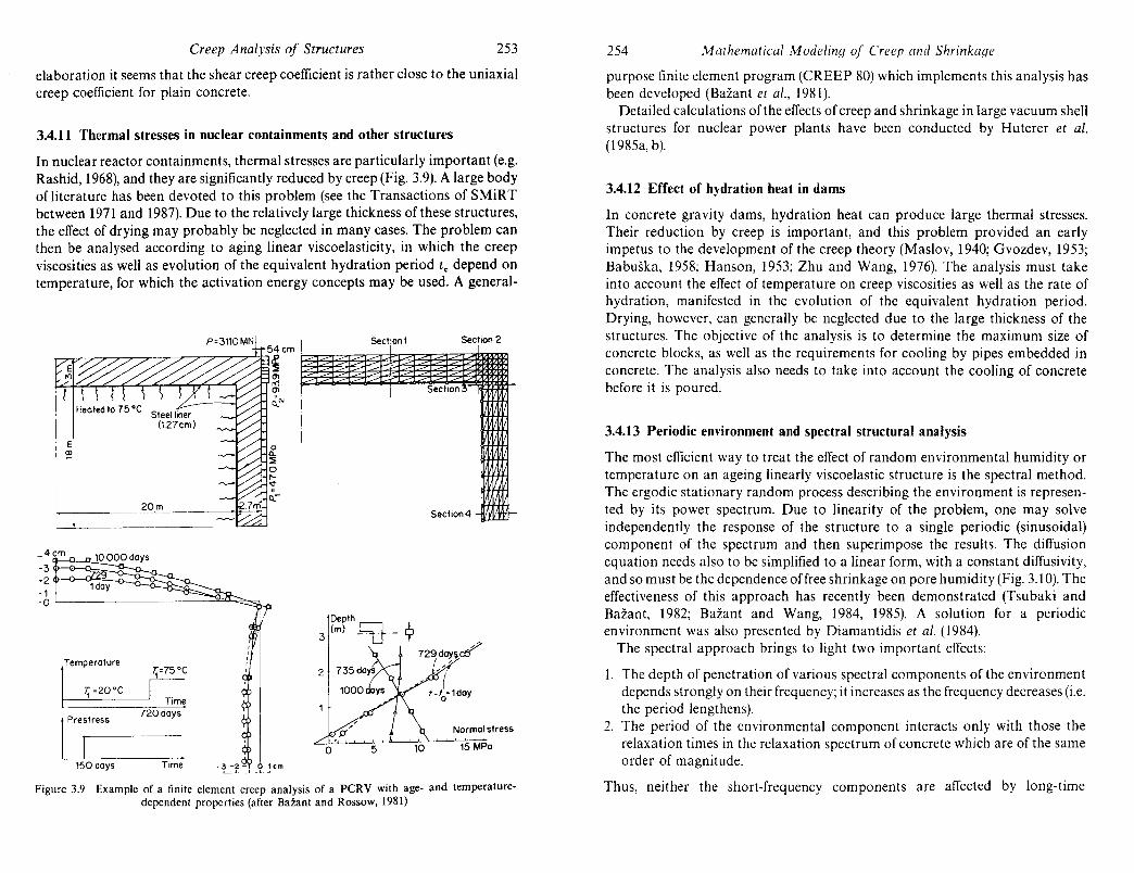
Creep Analysis of Structures 253
elaboration it seems that the shear creep coefficient is rather close to the uniaxial creep coefficient for plain concrete.
3.4.11 Thermal stresses in nuclear containments and other structures
In nuclear reactor containments, thermal stresses are particularly important (e.g. Rashid, 1968), and they are significantly reduced by creep (Fig. 3.9). A large body of literature has been devoted to this problem (see the Transactions of SMiRT between 1971 and 1987). Due to the relatively large thickness of these structures, the effect of drying may probably be neglected in many cases. The problem can then be analysed according to aging linear viscoelasticity, in which the creep viscosities as well as evolution of the equivalent hydration period to depend on temperature, for which the activation energy concepts may be used. A general-
Temperature T,=75 DC
Depth J.. 3 (m) ~- l' /
729 day~ c:tf'
7.;=20DC Time
720days 1 Prestress
I Normal stress
15 MPa
150 days Time
Figure 3.9 Example of a finite element creep analysis of a PCRV with age- and temperaturedependent properties (after Bazant and Rossow, 1981)
254 ,'I1athematical ,'I1odeling of Creep and Shrinkage
purpose finite element program (CREEP 80) which implements this analysis has been developed (Bazant et al., 1981).
Detailed calculations of the effects of creep and shrinkage in large vacuum shell structures for nuclear power plants have been conducted by Huterer et al. (1985a, b).
3.4.12 Effect of hydration heat in dams
In concrete gravity dams, hydration heat can produce large thermal stresses. Their reduction by creep is important, and this problem provided an early impetus to the development of the creep theory (Maslov, 1940; Gvozdev, 1953; Babuska, 1958: Hanson, 1953; Zhu and Wang, 1976). The analysis must take into account the effect of temperature on creep viscosities as well as the rate of hydration, manifested in the evolution of the equivalent hydration period. Drying, however, can generally be neglected due to the large thickness of the structures. The objective of the analysis is to determine the maximum size of concrete blocks, as well as the requirements for cooling by pipes embedded in concrete. The analysis also needs to take into account the cooling of concrete before it is poured.
3.4.13 Periodic environment and spectral structural analysis
The most efficient way to treat the effect of random environmental humidity or temperature on an ageing linearly viscoelastic structure is the spectral method. The ergodic stationary random process describing the environment is represented by its power spectrum. Due to linearity of the problem, one may solve independently the response of the structure to a single periodic (sinusoidal) component of the spectrum and then superimpose the results. The diffusion cquation needs also to be simplified to a linear form, with a constant diffusivity, and so must be the dependence offree shrinkage on pore humidity (Fig. 3.10). The effectiveness of this approach has recently been demonstrated (Tsubaki and Bazant, 1982; Bazant and Wang, 1984, 1985). A solution for a periodic environment was also presented by Diamantidis et al. (1984).
The spectral approach brings to light two important effects:
1. The depth of penetration of various spectral components of the environment depends strongly on their frequency; it increases as the frequency decreases (i.e. the period lengthens).
2. The period of the environmental component interacts only with those the relaxation times in the relaxation spectrum of concrete which are of the same order of magnitude.
Thus, neither the short-frequency components are affected by long-time

1.75
on
~ 150
"0 -0 ~ '0 c: 2 1 25 Ii ~ "0
Creep Analysis of Structures
01=0 -, b ~ (b)
r I /'
/'
T ~~--I 1 0
1 b
0 1 tJ 2 tJ 1 2 i "I
~; 28 days
2 3 24 25 26 48 49 50 Time I-Io(years)
Figure 3.10 (a) Cylindrical vessel and random variation of surface humid.ity h; (b) one-dimensional discretization of cylindrical wall; (c) time evolutIOn of standard deviation of radial stress (after Bazan! and Wang,
1985)
255 256 Mathl?lnatical Modeling of Creep and Shrinkage
creep, nor are the long-frequency components affected by short-time creep. Consequently, the effects of the random fluctuating part are very different for structures of different sizes or shapes, a fact which is ignored in the present design practice.
3.4.14 Viscoelastic stability: columns and shells
When the non-linearity of creep is taken into account, the effect of creep may be described in terms of the column or shell lifetime, expressing the time at which the buckli.ng deflections due to initial imperfections approach infinity (based on a linear bending theory). In the linear viscoelastic approximation, however, there is no lifetime; the deflection becomes infinite either suddenly (elastically) or at infinite time. Thus, in the linear context, the design for stability must be based either on the attainment of intolerably large deflections due to initial imperfections, or on the value of the long-time critical load which causes infinite deflection at infinite time (Fig. 3.11). However, the latter approach, widely used in nonaging viscoelasticity, is less than satisfactory for concrete, since the evolution of creep properties as a function of age has no effect on the long-time critical load. This load depends only on the asymptotic creep properties at an infinite age at loading. Thus, the first approach, based on the magnitude of buckling deflections, is preferable.
In the early researches, buckling deflections were calculated from simplified creep laws by reducing the problem to a differential equation with age-dependent coefficients; this was done for the rate-of-creep method (Naerlovic, 1960) as well as the Arutyunian formulation. For the latter, the problem was solved in terms of the incomplete gamma functions (Bazant, 1968b). Distefano 1965, Distefano and Sackman (1967), and Sackman (1963) studied the problem from the viewpoint of history integrals and Tauberian theorems. Subsequently, Bazant and Najjar (1973) presented creep buckling formulae based on the age-adjusted effective modulus method and showed that their predictions are very close to the accurate solutions obtained in step-by-step calculations using the integral-type creep law.
Using the integral operator formulation, Lazic (1985b) developed for the compliance function of any given form an accurate solution for the long-time critical load of a composite column, applicable to any boundary conditions and a constant cross-section. In two special cases, the long-time critical load linearly depends on the relaxation function (when the centres of gravity of concrete and of all the steel parts coincide and when the cross-section becomes homogeneous).
For a reinforced column of a symmetric cross-section, the creep deflection in excess of the elastic short-time deflection (Fig. 3.11; Bazant, 1968b) is given by
W~ax l-Us/l tr ) 1;(t,to) \\'max (t) = (1 P fpO ) (P" -;-----P) I -1 --( -)-:;:--( )
- "cr cr! - + X t, to 'i' t, to (3.39)

Creep Analysis of Structures 257
(b)
(a) 0.8,--,---r--,----,---,.----,
0.6 r--+------f__
p ---p _075 - -=t:::::::=1 E
0.4 t---t-----"7i"'-?,..-f==-=:l~O~====;~=1 1.5 2.0
0.2 t-~f"'---+--+--+--+-------1
2 5 10 20 50 100 1'J
a(CO)
70
",~60 ......
~
'" c 2 5.0 -u Q)
;;: Q)
"0 Q)
> - 4.0 .2 Q)
ct:
3.0
20
t -t' (days)
Figure 3.11 Creep buckling deflection of reinforced concrete column (a) calculated according to linear aging viscoelasticity (b, c); a -closed-form solution in terms of incomplete gamma function for aging standard solid (after Bazant, 1968); b-exact numerical step-by-step solution for general aging creep law compared with other methods (EMM = efI modulus, AEMM = age-adjusted eIT. modulus, ReM = rate of creep, RFM = ratio of flow, LM = Levi's, AM = Arutyunyuan's method (after Bazant
and Najjar, 1973)
258 Mathematical Modeling of. Creep and Shrinkage
in which wm .. (t) = maximum ordinate of the deflection curve at time t, w~ .. = maximum ordinate of the initial imperfect shape of the column, assumed to be sinusoidal; PCP P~r = buckling loads of an elastic column with concrete modulus Ec(t) or E" (t, to); P = axial compression load ofthe column, to = age of concrete at load application; Is, Itr = centroidal moments of inertia of steel and of the entire transformed cross-section with modulus E"(t, to). Similar equations can be written for creep buckling deflections of continuous beams, frames, arches, plates, shells, etc., in complete analogy to elastic stability theory.
The fact that coefficient X applies to creep buckling just as well as it does to relaxation problems confirms that this coefficient does not really introduce any correction for stress relaxation per se and is therefore properly called the aging coefficient (instead of the initially used term the relaxation coefficient).
Long-time stability of concrete structures is often checked by simply replacing the elastic modulus E in the corresponding elastic critical load formula with the effective modulus Eof ' The resulting formulae are somewhat simpler than those of the age-adjusted effective modulus method. This approach is the standard practice for checking the long-time stability of concrete shells (see, e.g. Kollar and Dulacska, 1984) and is also implied in the code formulae for columns, e.g. in the ACI Code. Compared to the use of the age-adjusted effective modulus, the use of the effective modulus is generally on the safe side in the case of buckling problems. However, it implies that the actual safety factor for a structure loaded at a high age is less than that for a structure loaded at a low age, while ideally it should be the same.
3.5 NON-LINEAR EFFECTS IN STRUCTURES
The linear analysis just reviewed often does not give an accurate picture of the structural behaviour, and if certain additional non-linear effects are not taken into account, the error may remain so large that little benefit is derived from the linear analysis. We will now review the basic types of non-linear effects.
3.5.1 Buckling and long-time stability
For buckling instability of columns under long-term loads it is important to realize that the specific creep (creep per unit stress) sharply increases as the peak stress is approached. This enables one to obtain, within a geometrically linear theory, an infinite deflection within a finite time. This lifetime serves as a more realistic indicator oflong-term stability. In contrast to linear analysis, the lifetime and the critical permanent load that corresponds to this lifetime depend not only on the asymptotic creep properties for very long times, but also on the intermediate and initial creep properties, including the material aging as it interacts with the stress history.
Non-linear buckling of columns (Fig. 3.12) has been studied by Manuel and
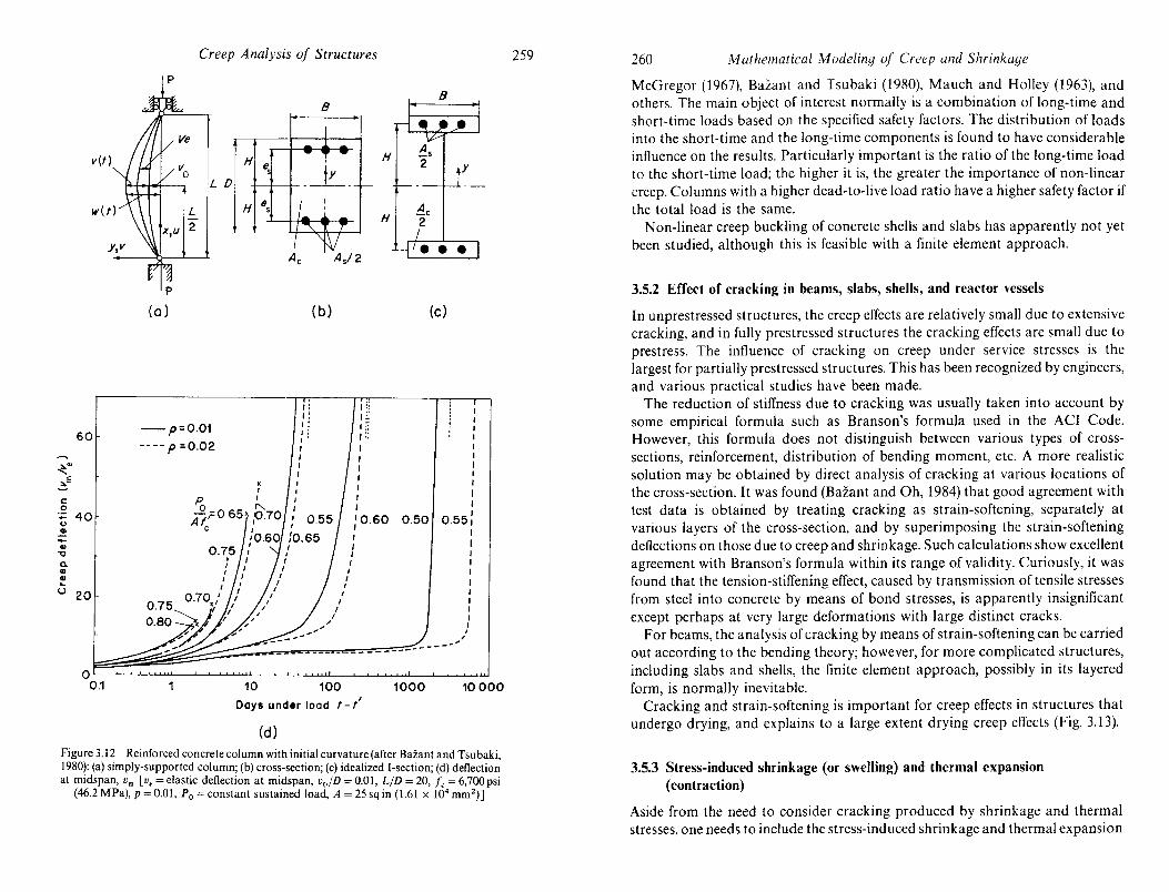
60 -p=0.01
---- P =0.02 ~ .. "" ~E c .~ 40 -()
CD .... CD
"0
Co CD
~ u 20
10
I I I I I I I
I I
I I ,-
".-
I I
'0.60 0.50 I I , , ,
I , I
--- ----------
100 1000 Days under load t - /'
(d)
0.55, I I I I I I ,
-_ .....
I I I , , ,
10000
Figure 3.12 Reinforced concrete column with initial curvature (after Bazant and Tsubaki, 1980): (a) simply-supported column; (b) cross-section; (c) idealized I-section; (d) deflection at midspan, Vrn [v, = elastic deflection at midspan, voiD = 0.01, LID = 20, Ie = 6,700 psi
(46.2 MPa), p = 0.01, Po = constant sustained load, A = 25 sq in (1.61 x 104 mm2)]
260 Mathematical Modeling of Creep and Shrinkage
McGregor (1967), Bazant and Tsubaki (1980), Mauch and Holley (1963), and others. The main object of interest normally is a combination of long-time and short-time loads based on the specified safety factors. The distribution of loads into the short-time and the long-time components is found to have considerable influence on the results. Particularly important is the ratio of the long-time load to the short-time load; the higher it is, the greater the importance of non-linear creep. Columns with a higher dead-to-live load ratio have a higher safety factor if the total load is the same.
Non-linear creep buckling of concrete shells and slabs has apparently not yet been studied, although this is feasible with a finite element approach.
3.5.2 Effect of cracking in beams, slabs, shells, and reactor vessels
In unprestressed structures, the creep effects are relatively small due to extensive cracking, and in fully prestressed structures the cracking effects are small due to prestress. The influence of cracking on creep under service stresses is the largest for partially prestressed structures. This has been recognized by engineers, and various practical studies have been made.
The reduction of stiffness due to cracking was usually taken into account by some empirical formula such as Branson's formula used in the ACI Code. However, this formula does not distinguish between various types of crosssections, reinforcement, distribution of bending moment, etc. A more realistic solution may be obtained by direct analysis of cracking at various locations of the cross-section. It was found (Bazant and Oh, 1984) that good agreement with test data is obtained by treating cracking as strain-softening, separately at various layers of the cross-section, and by superimposing the strain-softening deflections on those due to creep and shrinkage. Such calculations show excellent agreement with Branson's formula within its range of validity. Curiously, it was found that the tension-stiffening effect, caused by transmission of tensile stresses from steel into concrete by means of bond stresses, is apparently insignificant except perhaps at very large deformations with large distinct cracks.
F or beams, the analysis of cracking by means of strain-softening can be carried out according to the bending theory; however, for more complicated structures, including slabs and shells, the finite element approach, possibly in its layered form, is normally inevitable.
Cracking and strain-softening is important for creep effects in structures that undergo drying, and explains to a large extent drying creep effects (Fig. 3.13).
3.5.3 Stress-induced shrinkage (or swelling) and thermal expansion (contraction)
Aside from the need to consider cracking produced by shrinkage and thermal stresses, one needs to include the stress-induced shrinkage and thermal expansion

a. o o :r:
o "C o
a::
Creep Analysis of Structures
\0 c:i
261
" .~ '" " 0-S o " :e:
, __ ...J..LjJL-'----c'---'o L-_--ll.L...l--'_~...J 00' 0- c:i 0 0 0
o '" :----'-'::!,.........---'--:::---'o ~
o 0 .;; u
, __ ----.,---__ ----,0 ICl \0 ~ __ ;--___ '~o ,-_--,.--__ --,0 Z
-0
1\ I~
If)
t o o o N
\0 c:i
1Cl~ 0"
o 0 0 o!-....LL..o:k'-'---'-o=-- c:i oL--..,oo-Ll-..,oo..IL.-.lJo 0 o.!:---.L.L-'o-.u........--=-~ 0 o 000000 ICl ICl ICl \0 \0 ICl ICl I I" ~ rt?
(lsd) SSaJIS
" oj
... ~~ G)~ 00 " 0- 'C :::-~
~2; ..c: U -0 c oj
'" oj 'N oj
co
262 Mathematical Modeling of Creep and Shrinkage
to obtain a realistic picture of the environmental effects. While these effects can be easily taken into account in finite element analysis, they inevitably have to be neglected in the simpler linearized solution. It should be kept in mind, though, that the linearized analysis of random environment by the spectral approach (Bazant and Wang, 1984, 1985), as well as the simplified models based on a linear humidity distribution solution for a single component periodic environment (Diamantidis et az', 1984), describe only a part of the real behaviour, and the nonlinear effects will have to be considered eventually.
3.5.4 Effect of cyclic creep on bridge deflections
A periodically fluctuating stress component superimposed on a constant stress causes an increase of creep beyond that predicted according to the principle of superposition. This is of some importance for prestressed concrete bridges, in which the repeated load component is significant and is combined with the stress fluctuations due to environmental effects.
The increase of creep due to cyclic loads occurs primarily near the upper and lower faces of the beam, and is zero at the neutral axis. Thus, the beam faces undergo additional shortening which does not occur at the neutral axis. This leads to additional self-equilibrated stresses in the cross-section, tensile at the top and bottom faces and compressive at the neutral axis (Fig. 3.14).
z
o ___ CT~
5 _ CT 9
h max CT
d CT
Figure 3.14 Effect of cyclic creep on beam deflection (Bazant, 1968a)

Creep Analysis of Structures 263
If the cross-section is non-symmetric, as is usually the case, the additional cyclic creep is larger at the face which is further from the neutral axis than it is at the opposite face. Thus, the cyclic creep causes an additional warping of the beam. In a redundant structure, this further induces additional redundant internal forces. These effects have been analysed for box girder bridges (Fig. 3.14) and were found to have an appreciable although not dominant influence.
At high stress levels beyond the working stress range, the creep response due to repeated loads becomes similar to plastic shakedown, and may exhibit a timedependent version of incremental collapse, as well as fatigue.
3.5.5 Effect of clay consolidation in foundation
On certain sites, structures have to be founded on clay which undergoes gradual consolidation. This causes redistribution of internal forces in a redundant structure, and at the same time the gradual changes in support reactions affect the amount of clay consolidation in the foundation. Thus, the creep in the structure and the consolidation of clay (including the creep of clay) interact.
Since the dependence of clay consolidation settlements on the stress in clay is highly non-linear, the entire structure-soil interaction problem is rendered nonlinear as well. The problem has been analysed using a secant linearized model for clay (Bazant, 1964c; Fig. 3.15). An iterative succession of such linear analyses can be used to obtain an accurate non-linear solution.
3.5.6 Viscoplastic analysis and high-temperature behavior
Three-dimensional viscoplastic constitutive equations which represent a generalization of plasticity models for concrete have been recently applied to some problems of nuclear reactor vessels in hypothetical high-temperature core-
34
IX2
~ .. .J5=P2 <;tL.lll,lJ l
Figure 3.15 ElTect of clay consolidation in foundation
264 M atilel1Jaticai }\,f ndi'linq nf Creep and Shrinkage
disruptive accident conditions (Marchertas and Kennedy, 1983; Pfeiffer et al., 1985; Thelandersson, 1983; Bazant, 1983). At high temperature, the rapid viscous flow of concrete near the strength limit causes a rapid relaxation of the peak stresses in the structure and a rapid redistribution of internal forces. This is important for the problem of hot spots in heated walls, which is of interest not only for nuclear reactor structures but also for fire resistance.
The high local stresses produced by rapid heating limited to a small area may become rapidly relaxed. However, once the stress relief capability of the stress redistribution due to structural redundancy is exhausted, the visco plastic behaviour at high temperature is dangerous since it may lead to large deformations and rapid structural collapse.
3.6 DESIGN FOR STOCHASTIC BEHAVIOR AND OBSERVATIONS ON STRUCTURES
Eventually, further progress will require the design engineers to recognize that all the effects in structures discussed in the preceding review are in reality stochastic. As will be seen in Chapter 5, the statistical variability of creep and shrinkage is enormous, although it can be greatly reduced by certain measures such as Bayesian statistics based on short-time measurements. It will be desirable to develop design methods which are based not on the mean predictions but on certain extreme values that are exceeded only with a small specified probability
such as 5 per cent. The Latin hypercube sampling approach (see Bazant and Liu in Chapter 5, and
Kfistek and Bazant 1987) can be combined with all of the methods described in this chapter to obtain statistical information. However, the stochastic process aspects can hardly be analysed in this manner.
Another practical method based on response surface fitting has been developed by Wi urn and Buyukozturk (1985). They applied the method to calculate the variability of the long-term deformation in a multiple-span bridge. The results indicate a large variability in the response due to randomness of the factors that influence creep and shrinkage. The major source of uncertainty is found to be the variability of the material properties of the concrete.
Various observations of creep and shrinkage effects in structures have been made in the past. However, comparisons of the results of analysis with measurements on structures have so far been of limited usefulness since typically only some of the intervening effects were analysed while others have been ei~her ignored or taken into account in an oversimplified manner. Successful venfication has often been claimed; however, a fundamental question arises as to the meaning of such verification when one obtains an excellent agreement with some very limited observations or test results while at the same time the assumptions of analysis strongly disagree with known measurements of material
behaviour.

Creep Analysis of Structures 265
3.7 CONCLUDING REMARKS
In this chapter, linear and non-linear analysis of structures for the effects of creep and shrinkage have been discussed. The basic assumptions of analysis, and the current code recommendations have been reviewed and comparisons of the methods of analysis made. Creep and shrinkage effects have been considered for different types of structures under a variety of loading conditions.
The effects of creep and shrinkage on structures can be very large, generally larger than the effects of short-time loadings. Although stress redistributions that occur due to long-term effects may frequently result in favourable structural conditions, for certain cases differential creep and shrinkage in various parts of a structure can cause deleterious cracking, followed by deterioration of the structure. For certain structural situations, creep and shrinkage may unfavourably alter the safety margin against the collapse of the structure under short-time overloads. Creep in slender structures may cause the critical loads for long-time instability to become much less than the elastic critical loads.
Considerable development has taken place in recent years in the area of nonlinear creep analysis of concrete structures. However, nearly all the practical applications governed by the current codes or recommendations rely on the linearity assumption. This assumption may lead to acceptable results for service load conditions. Aging linearly viscoelastic material behaviour gives rise to a variety of effects in structures. Presently, these effects are well understood and can be analysed without difficulty. Generally, however, linear analysis does not lead to a realistic prediction of the structural behaviour for the full range ofload levels. For example, effects such as material aging as it interacts with the stress history may significantly influence the lifetime and the critical permanent load that corresponds to that lifetime. A variety of non-linear effects in structures are discussed.
Finally, it is emphasized that all the creep effects in structures are in reality stochastic. The properties of concrete exhibit a large variability due to randomness of the factors that influence creep and shrinkage. These variations introduce large scatter in the response of structures, which makes it difficult to predict the long-term response accurately.
REFERENCES AND BIBLIOGRAPHY
ACI Committee 209 Report No. ACI 209 R-82 (1982), Prediction of creep shrinkage and temperature effects in concrete structures, prepared by D. J. Carreira, Z. P. Bazant and D. E. Branson, ACI Spec. Pub I. SP76, Am. Concrete Inst., Detroit, pp. 193-300.
Aguinaga-Zapata, M., and Bazant, Z. P. (1986), Creep deflections in slab buildings and forces in shores during construction, ACI Journal, 83, pp. 719-26 (with discussion, 1987, pp. 361-3).
Aleksandrovskii, S. V. (1966), Analysis of Plain and Reinforced Concrete Structures for Temperature and Moisture Effects with Account of Creep, (in Russian), Stroyizdat, Moscow, 443 pp.
266 Mathematical .Modeling of Creep and Shrinkage
American Concrete Institute, (1983), Building Code Requirement for Reinforced Concrete (ACI318-83).
Anderson, C. A. (1980), Numerical creep analysis of structures, Los Alamos Scientific Laboratory Rep. LA-UR-80-2585, 1980, also in Z. P. Bazant and F. H. Wittman (eds), Creep and Shrinkage in Concrete Structures, Wiley, London, pp. 259-303.
Anderson, C. A., Smith, P. D., and Carruthers, L. M. (1982), NONSAP-C: A Nonlinear Strain Analysis Program for Concrete Containments under Static Dynamic and LongTerm Loadings, Report NUREG/CR0416, LA-7496-MS, Rev. 1, R7, R8, Los Alamos National Laboratory, New Mexico, Jan. 1982 (available from NTIS, Springfield, Va).
Argyris, 1. H., Pister, K. S., Szimmat, J., and Willam, K.1. (1977), Unified concepts of constitutive modeling and numerical solution methods for concrete creep problems, Comput. Meth. Appl. Mech. Eng., to, 199-246.
Argyris,1. H., Vaz, L. E., and Willam, K. 1. (1978), Improved solution methods for inelastic rate problems, Comput. Meth. Appl. Mech. Eng., 16, 231-77.
Arutyunian, N. Kh. (1952), Some Problems in the Theory of Creep (in Russian), Techteorizdat, Moscow; Eng!. transl. Pergamon Press (1966).
Babuska, I. (1958), On rheologic properties of concrete (in Czech), Stauenicky Casopis SA V, Bratislava, 6( I).
Bastgen, K. (1979), Zum Spannungs-Dehnungs-Zeit-Verhalten von Beton, Relaxation, Kriechen und deren Wechselwirkung, Dissertation, Technical University Aachen.
Bazant, Z. P. (1961), Effect of creep and shrinkage of concrete in statistically indeterminate structures with concrete of nonuniform age (in Czech), lnzenyrske Stauby (SNTL, Prague), 9, 225-8.
Bazant, Z. P. (1962), Theory of creep and shrinkage of. concrete in nonhomogeneous structures and cross sections (in Czech), Starehnicky Casopis SA V, 10, 552-76.
Bazant, Z. P. (l964a), Approximate methods of analysis of creep and shrinkage in nonhomogeneous structures and use of computers (in Czech), Stavebnicky Casopi.\ SA V, 12,414-31.
Bazant, Z. P. (l964b), Die Berechnung des Kriechens und Schwindens nichtomogener Betonkonstruktionen, Proc. 7th Congr., Int. Assoc. for Bridge and Struct. Eng., Rio de Janeiro, pp. 887-96.
BaZant, Z. P. (I 964c), Time interactton of statically indeterminate concrete structures with subsoil (in Czech), Starebnicky Casopis SA V, 12, 542-58.
Bazant, Z. P. (1965), Effect of creep on long-term stability and buckling strength of concrete columns (in Czech), Proc. 5th Nat. Conf. on Prestressed Concrete, Zilina, Czechoslovakia, pp. 115-32.
Bazant, Z. P. (1966a), Creep of Concrete in Structural Analysis (in Czech), State Publishers of Technical Literature SNTL, Prague.
Bazant, Z. P. (1966b), Phenomenolo$ical theories for creep of concrete based on rheological models, Acta Technica CSA V, Prague, 11, 82-109.
Bazant, Z. P. (1967), Linear creep problems solved by a succession of generalized thermoelasticity problems, Acta Technica CSA V, Prague, 12, 581-94.
Bazant, Z. P. (l968a), Langzeitige Durchbiegungen von Spannbetonbriicken infolge des Schwingkriechens unter Verkehrslasten, Beton- und Stahlbetonbau, 63, 282-5.
Bazant, Z. P. (1968b), Creep stability and buckling strength of concrete columns, Mag. of Concrete Research, 20, 85-94.
Bazant, Z. P. (1970), Numerical analysis of creep of an indeterminate composite beam, J. Appl. Mech .. ASME, 37,1161-4.
Bazant, Z. P. (197Ia), Numerical analysis of creep of reinforced plates, Acta Technica Hung., 70, 415-8.

Creep Analysis of Structures 267
Bazant, Z. P. (1971 b), Numerical solution of non-linear creep problems with application to plates, Int. J. Solids Struct., 7, 83-97. '"
Bazant, Z. P. (1972), Prediction of concrete creep effects usmg age-adjusted effectIve modulus method, J. Am. Concr. Inst., 69, 212-7.
Bazant, Z. P. (1975), Theory of creep and shrinkage in concrete structures: a precis of recent developments, Mech. Today, 2, 1-93.
Bazant, Z. P. (1982), Mathematical models for creep and shrinkage of concrete. In Z. P. Bazant and F. H. Wittmann (eds), Creep and Shrinkage in Concrete Structures Ch. 7, Wiley, New York, NY, pp. 163-258.
Bazant, Z. P. (1982), Mathematical models for creep and shrinkage of concrete. In Z. P. Bazant and F. H. Wittman (eds), Creep and Shrinkage in Concrete Structures, John Wiley & Sons, 163-256.
Bazant, Z. P. (1983), Mathematical model for creep and thermal shrinkage of concrete at high temperature, Nucl. Engng. and Design, 76, 183-91.
Bazant, Z. P. (1986), Mechanics of distributed cracking, Applied Mechanics Reuiews, ASME, 39(5), 675-705.
Bazant, Z. P. (1987), Matrix force-displacement relations in ageing viscoelasticity, J. Engng. Mech. ASCE, 113(8), 1239-43.
Bazant, Z. P., Carreira, D. )., and Walser, A. (1975), Creep and shrinkage in reactor containment shells, J. Struct. Diu., ASCE, 202(STlO), Proc. Paper 11632, 2117-31.
Bazant, Z. P., and Chern, J. C. (1984a), Rate-type concrete creep law with reduced time, J. Engng. Mech. Diu., ASCE, 110, 329-40.
Bazant, Z. P., and Chern, J. C. (1984b), Double power logarithmic law for concrete creep, Cem. Concrete Res., 14, 793-806; Log-double power law for concrete creep, ACI Journal, 82(1985), 665-75.
Bazant, Z. P., and Chern, ). C. (\985), Strain-softening with creep and exponential algorithm, J. Engng. Mech. ASCE, t11(EM5), 391-415.
Bazant, Z. P., and Kim, S. S. (1979a), Nonlinear creep of concrete~adaptation and flow, J. Engng. Mech. Diu. ASCE, 105(EM3), 419-46.
Bazant,'). P., and Kim, S. S. (1979b), Approximate relaxation function for concrete, J. Struct. Diu., ASCE, 105(STl2), 2695-705.
Bazant, Z. P., and Lin, K.-L. (1985), Random creep and shrinkage in structures: sampling, J. Struct. Engng., ASCE, 111, 11/3-34.
Bazant, Z. P., and Najjar, L. J. (1973), Comparison of approximate linear methods for concrete creep, J. Struct. Diu., ASCE, 99,1851-74.
Bazant, Z. P., and Oh, B. H. (1984), Deformation of progressively cracking reinforced concrete beams, J. Am. ConeI'. Inst., 81, 268-78.
Bazant, Z. P., and Ong, J. S. (1983), Creep in continuous beam built span-by-span, J. Struct. Engng. ASCE, 109, July, 1648-68.
Bazant, Z. P., and Panula, L. (1978), Practical prediction of creep and shrinkage of concrete, Materials and Structures (RILEM, Paris), Parts I and II, 11 (1978), pp. 307-28; Parts III and IV, pp. 415-34; Parts V and VI, 12(1979), pp. 169-83.
Bazant, Z. P., Rossow, E. c., and Horrigmoe, G. (1981), Finite element program for creep analysis of concrete structures, Proc. 6th Int. Conf. on Structural Mechanics in Reactor Technology, Paris, Paper H2/1.
Bazant, Z. P., and Tsubaki, T (1980), Nonlinear creep buckling of reinforced concrete columns, J. Struct. Diu., ASCE 106, 2235-56.
Bazant, Z. P., Tsubaki, T, and Celep, Z. (1982), Singular history integral for creep rate of concrete, J. Engng. Mech. Diu., ASCE. .
Bazant, Z. P., and Thonguthai, W. (1978), Pore pressure and drying of concrete at high temperature, J. Engng. Mech. Diu., ASCE, 104, 1058-80.
268 Afathemarical Modeling of Creep and Shrinkage
Bazant, Z. P., and Wang, T S. (1984), Spectral analysis of random shrinkage stresses in concrete, J. Engrg. Meeh. DiL'., ASCE, 110, 173-86.
Bazant, Z. P., and Wang, T. S. (1985), Spectral finite element analysis of random shrinkage in concrete, J. Struet. £ngng., ASC£, 110,2196-2211.
Bazant, Z. P., and Wu, S. T (1974), Rate-type creep law of ageing concrete based on Maxwell chain, Materials and Structures (RILEM, Paris), 7, 45-60.
Bazant, Z. P., and Kim, Joong-koo (1987), Segmental Box Girder: Deflection Probability and Bayesian Updating, Report, Centre for Concrete and Geomaterials, Northwestern University, Evanston, submitted to ASCE J. of Struct. Engng.
Becker, J., and Bresler, B. (1977), Reinforced concrete frames in fire environment, J. Struct. Div., ASC£, 103,211-24.
Boltzmann, Z. (1876), Zur Theorie der Elastischen Nachwirkung, Stizber. Akad. Wiss., Wiener 'Berieht 70, Wiss. Abh., 1(1874),275-306; see also Pogg. Ann. Phys., 7, 624.
Branson, D. E., Meyers, B. L, and Kripanarayanan, K. M. (l970a), Time-dependent deformation of non-composite and composite prestressed concrete structures, Highway Res. Rec., No. 324, 15-33.
Bresler, 8., and Selna, L. (1964), Analysis of time-dependent behavior of reinforced concrete structures, ACI Symp. on Creep of Concrete, ACI Spec. Pub\. SP-9.
Bridge, R. Q. (1979), Composite columns under sustained load, J. Struct. Diu., ASCE, 105, 563-76.
Chiorino, M. A. el al. (1984), CEB Design Manual on Structural effects of time-dependent behaviour of concrete, CEB Bulletin d'lnformation, No. 142/142 bis, Georgi, SaintSaphorin. Switzerland, 391 pp.
CEB-FIP (1970), International Recommendations for the AnalYSis and Construction of Concrete Structures, 2nd edn., Cement and Concrete Assoc., London.
CEB-FIP (1978), Model code for concrete structures, Comite Euro-International du Beron. Paris, Vo!' 2, Appendix e.
Cederberg, H., and David, M. (1969), Computation of creep effects in prestressed concrete pressure vessels using dynamic relaxation, Nucl. Engng. and Design, 9, 439-48.
Chetoui, S. (1985), Evaluation des proprietes effectives des materiaux heterogenes anisotropes a constituants viscoelastiques, Thesis, Ecole Nationale dts Ponts et Chaussees, Paris; see also, Chetoui, S., Navi, P., and Huet, C. (1986), Recherches sur revaluation des proprietes macroscopiques des materiaux heterogenes viscoelastiques anisotropes. In C. Huet, D. Bourgoin and S. Richemond (1986).. '.
Chiorino, M. A., Creazza, G., Mola, F., and Napoli, P. (1986), AnalYSIS of agelllg VISCOelastic structures with n-redundant elastic restraints, Preprint. In Z. P. Bazant (cd.), 4th RI LEM Intern. Symp. on Creep and Shrinkage of Concrete: Mathematical Modeliny, Northwestern University, Evanston, Ill., pp. 623-44.
Chiorino, M. A., Losana, G., and Napoli, P. (1982), Influence of creep on stresses due to temperature variations in concrete structures, CEB Bull. No. 154, Paris.
Chiorino, M. A., and Mola, F. (1982), Analysis of linear viscoelastic structures subjected to . delayed restraints. In F. H. Wittman (ed.), Fundamental Research on Creep and Shrinkage of Concrete, Martinus Nijhoff, The Hague.
Diamantidis, D., Madsen, H. 0., and Rackwitz, R. (1984), On the variability of the creep coefficient of structural concrete, M att!riaux et Constructions (RILEM, Paris), 17(100), 321-8.
Dilger, W. H., and Abele, G. (1974), Initial and time-dependent shear deflections of reinforced concrete T-beams, ACI-SP43, Detroit, pp. 487-514.
Dilger, W. H. (1981), Creep analysis of concrete structures, Symp. on the Design for Creep and Shrinkage in Concrete Structures, ACI Spec. Pub!. No. 76, pp. 325-39.
Dilger, W. H. (1982), Creep analysis of prestressed concrete members using creeptransformed section properties, J. Prestress. Concr. Ins!., 27(1), Jan.-Feb., pp. 98-117.

Creep Analysis of Structures 269
Dischinger, F. (1937), Untersuchungen uber die Knicksicherheit, die Elastiche Verformung und das Kriechen des Betons bei Bogenbriicken, Der Bauingenieur, 18,487-520, 539-52, 595-62l.
Dischinger, F. (1939), Elastische und plastische Verformungen bei Eisenbetontragwerke, Der Bauingenieur, 20, 53-63, 286-94, 426-37, 563-72. . . .
Distefano, J. N., and Sackman, 1. (1967), Stability analysis of nonlInear and vIscoelastIc column, ZAM M, 47; also Quart. App/. Math., 24( 1966), 133-4l.
Distefano, J. N. (1965), Creep buckling of slender columns, 1. Struct. Div., ASCE, 91, June, 127-50; also Publ. IABSE, 21(1961), 37-48.
Drysdale, R. G., and Huggins, M. W. (1971), Sustained biaxial load on slender concrete columns, J. Struct. Div., ASCE, 97, 1423-43.
Duhamel, J. M. C. (1838), Mcmoire sur Ie calcul des action moU:culaires developees par les changements de temperature dans les corps solides, France, 5, 440-98.
England, G. L., and Illston, 1. M. (1965), Methods of computing stress in concrete from a history of measured strain, Civ. Eng. Pub!. Works Rev., pp. 513-7, 692-4, 845-7.
Finsterwalder, V., and Knittel, G. (1955), Ergebnisse von Kriech- und Schwindmessungen an Spannbetonbauwerken, Der Bauingenieur, 1958, No.8 (also Beton u. Stahlbetonbau, No.5 (1958), 136-44).
Frenay, J. W. (1985), Shear transfer across a single crack in plain and reinforced concrete under sustained loading, Stevin Lab. Reports 5-85-5/7/13, Delft University of Technology, Delft, Netherlands.
Foure, B. (1978), Le flambement des poteaux compte tenu du fluage du beton, Annales de l'Institut Technique du Biltiment et des Travaux Publics, 359, Paris, 4-58.
Ghali, A., Neville, A. M., and Jha, P. C. (1967), Effect of elastic and creep recoveries of concrete on loss of prestress, J. Am. Concr. Inst., 64, 802-10.
Gvozdev, A. A. (1953), Thermal-shrinkage deformations in massive concrete blocks (in Russian), Izvestia A.N. SSSR, OTN, 17(4).
Haas, W. (1982), Numerical analysis of creep and shrinkage in concrete structures. In F. H. Wittmann, (ed.), Fundamental Research on Creep and Shrinkage, Martinus Nijhoff, The Hague. .
Hannant, D. J. (1967), Strain behavior of concrete up to 95° C under compressIve stresses, Proc. Conj. on Prestressed Concrete Pressure Vessels, Group C, Paper 17, Institution of Civil Engineers, London, pp. 57 -7l.
Hannant, D. (1968), The mechanism of creep of concrete, Materials and Structures, (RILEM, Paris) 1, 403-10.
Hansen, T. C. (1960), Creep and stress relaxation in concrete, Proc. Swed. Cern. Concr. Res. Inst. (CBI), Royal Inst. Tech., Stockholm, No. 3l.
Hansen, T. C. (1964), Estimating stress relaxation from creep data, Mater. Res. Stand. (ASTM),4, 12-4.
Hanson, J. A. (1953), A ten-year study of creep properties of concrete, Concrete Lab. Report No. SP-38, US Dept. of the Interior, Bureau of Reclamation, Denver, Colo.
Huet, C. (1970), Sur i'evolution des contraintes et deformations dans le~ systemes multicouches constitues des materiaux visco-eiastiques presentant du vlellllssement, Compt. Rend. Acad. Sci., Paris, 270A, 213-5. . . . . ..
H uet, C. (1972a), Sur une application du calcul symbolique a la viscoeiastlclte non-lInealre, Compt. Rend. Acad. Sci. (Paris), 275A, 793-6. . ,
Huet, C. (1972b), Application a la viscoelasticite non-lineaire du calcul symbohque a plusieurs variables, Proc. IVth Int. Congr. Rheology, Lyon, France, Rheol. Acta, 12, 279-88 (1973).
Huet, C. (1973), Sur une methode de calcul en environnement variable de systemes physiques ou physico-chimiques a comportement differe, Compt. Rend. Acad. Sci. (Paris), 976A, 1469-71.
270 Mathematical Modeling of Creep and Shrinkage
Huet, C. (1974a), Operateurs integro-differentiels matriciels pour l'etude des systemes a reponse diffi:ree presentant du vieillissement, CampI. Rend. Acad. Sci. (Paris), 278A, 1119-22.
Huet, C. (I 974b), Viscoelasticite non-Iineaire et calcul symbolique, Cahiers Groupe Frans;. Rheol., 3(4), 150-9.
Huet, C. (1978), Operateurs matriciels pour la viscoelasticite avec vieillissement, CaMers Groupe Frans;. Rheo/., 4(6), 281-90.
Huet, C. (1980), Adaptation of Bazant's algorithm to the analysis of ageing viscoelastic composite structures, Materials and Structures (RILEM, Paris), 13, No. 75,91-8 (in French).
Huet, C. (1983), Thermodynamique des comportements rheologiques en variables naturelles, Rheol. Acta, 22, 245-59.
Huet, C. (1984a), Macroscopic rheology without functionals: the natural variables formalism. In Advances in Rheology, B. Mena et al. (eds.) (Proc. I Xth Int. Congr. Rheology, Acapulco), Vol. 1 (Theory), Mexico University Press.
Huet, C. (1985), Elements de thermomecanique des materiaux hetero?enes, Cours de materiaux de construction de l'Ecole Nationale des Ponts et Chaussees, Pans.
Huterer, 1., Brown, D. G., and Yanchula, S. (1985a), Darlington GS vacuum building, Nucl. Engng. and Design, 85, 119~40. ..
Huterer, J., Brown, D. G., Yanchula, S., and Cheng, P. C. (1985b), DarlIngton generatlllg station vacuum building, SMiRT8, Brussels, paper H6/2. . .
Iding, R., and Bresler, B. (1982), Prediction of shrinkage stresses and deformatIons III
concrete. In F. H. Wittman (ed.), Proc. Conf. on Fundamental Research In Creep and Shrinkage of Concrete, Martinus Nijhoff, The Hague. .. .
Jonasson, J E. (1978), Analysis of creep and shrinkage in concrete and ItS applIcatIon tc concrete top layers, Cern. Concr. Res., 8, 397-418. . .
Jonasson, J. E. (1977), Computer programs for non-linear analysis of concrete m VIew 01 shrinkage, creep, and temperature (in Swedish with English captIons and sum~ary) ForskningjResearch 7:77, Swedish Cement and Concrete Research Institute Stockholm. . ..
Jordaan, I. 1., and England, G. L. (1977), Creep of concrete: a consIstent engmeenn! approach, J. Engng. Mech. Div., ASCE, 103, March, 471 (with Discussion, 104, JUll( 1978,1020-5). .
Klug, P., and Wittmann, T. (1970), The correlation between creep deformatIOn and stres~ relaxation in concrete Materials and Structures (RILEM, Pans) 3, 75-80.
Kollar, L., and Dul<lcsk~, E. (1984), Buckling of Shells for Engineers, Wiley, Chichester New York, p. 242.
Kfistek, V., and Bazant, Z. P. (1987), Shear lag effect and uncertainty in concrete bm girder creep, J. Struct. Engng. ASCE, 113(3), pp. 557-74; also Bazant and Kfistek 4th RILEM Int. Symp. on Creep and Shrinkage: Math. Modeling, Evanston, 111.,1986 pp.675-84. .. ..
Kordina, K. (1975), Langzeitversuche and Stahlbetonstutzen, Deutscher Ausschuss fUl Stahlbeton, 250, Berlin, 1-36.
Kfistek, V., Maca, J., Sruma, V., and Vitek, J. L., (1982), Simplified calculation of strest relaxation in concrete, Inzen}'TSke Starby (SNTL, Prague), V(5-6), 299-306.
Lazit, 1. D. (1975), Application of the linear viscoelasticity in the theory of structur~s Collection of Papers of the Faculty of Civil Engineering in Belgrade, 16(1), Belgrade (If Serbo-Croatian).
Lazit,1. D. (1982), Approximate theory of composite and prestressed structures, Naucn< knjiga, Belgrade (in Serbo-Croatian). . .
Lazit, V. B., and Lazit, 1. D. (1977), Les contraintes et les pertes de precontramte dam les structures precontraintes, Annales de l'ITBTP, Paris, TMC211, 34-5 (in Ch. 3).

Creep Analysis of Structures 271
Lazit, l. D., and Lazit, V. B. (1981), Prevision des effects du fluage du beton dans les structure mixtes et precontraintes, Annales de l'lTBTP, Paris, TMC246, 26-52.
Lazit, V. B., and Lazit, l. D. (1982a), Stresses and displacements of composite and prestressed structures. In F. H. Wittman (ed.), Fundamental Research on Creep and Shrinkage of Concrete, Martinus Nijhoff, The Hague.
Lazit, l. D., and Lazit, V. B. (1982b), General theory of composite and prestresses structures, The Serbian Academy of Sciences and Arts, Monographs DXLII(22), Belgrade (in Serbo-Croatian).
Lazit,1. D., and Lazit, V. B. (1984a) Generalized age-adjusted effective modulus method for creep in composite beam structures. Part I - Theory, Cern. Con cr. Res., 14,819-932.
Lazit, l. D., and Lazit, V. B. (1984b), Effects of interaction of different materials. In B. Mena, A. Garcia-Rejon, and C. Rangel-Nafaile (eds), Advances in Rheology, UNAM, Mexico, pp. 361-8.
Lazit,1. D., and Lazic, V. B. (1985), Generalized age-adjusted effective modulus method for creep in composite beam structures. Part II-Applications, Cern. Concr. Res., 15, 1-12.
Lazit, V. B. (1985a), Stresses and displacements in composite beam structures, I zgradnja, 1, Belgrade, 5-17 (in Serbo-Croatian).
Lazit, V. B. (1985b), Flambement des poutres mixtes droites, Annales de I'ITBTP, Paris, TMC 273, 58-67. .
LeCamus, B. (1947), Recherches experimentales sur la deformation du beton et du beton arme, Part II, Annales Inst. Techn. du Batiment et des Travaux Publics, Paris.
Leong, T. W., and Warner, R. F. (1970), Creep and shrinkage in reinforced concrete beams, J. Struct. Div., ASCE, 96, 509-33.
Levi, F., and Pizzetti, G. (1951), Fluage, Plasticite, Precontrainte, Dunod, Paris. Lin, T. H. (1968), Theory of Inelastic Structures, Wiley, New York. Madsen, G. N. (1979), Matrix formulation for practical solution of concrete creep
problems, DIALOG 1-79, Danish Engineering Academy, Lyngby. Madsen, H. 0., and Bazant, Z. P. (1982), Uncertainty analysis of creep and shrinkage effects
in concrete structures, Report No. 82-2/665u, Center for Concrete and Geomaterials, Northwestern University, Evanston, Ill.
Mandel, 1. (1974), Un principe de correspondance pour les corps viscoelastiques lineaires vieillissants, IUT AM Symp. Mechanics of Viscoelastic Media and Bodies, Gothenburg, l. Huh (ed.), Springer.
Mandel, J. (1958), Sur les corps viscoelastiques lineaire dont les proprietes dependent de ('age, Compt. Rend. Seances Acad. Sci., 247, 175-8.
Manuel, R. F., and McGregor, 1. G. (1967), Analysis of prestressed reinforced concrete columns under sustained load, J. Am. Coner. Inst., 64, 12-23.
Marchertas, A. H., and Kennedy, l. M. (1983), Analytical response of concrete structures subjected to high temperature, SMiRT7, Chicago, paper H2/2.
Maslov, G. N. (1941), Thermal stress states in concrete masses, with consideration of concrete creep (in Russian), [zvestia N auchno-I ssledovatel'skogo I nstituta Gidrotekhniki, Gosenergoizdat, 28, 175-88.
Manuel, R. F., and McGregor, 1. G. (1967), Analysis of prestressed reinforced concrete columns under sustained load, J. Am. Concr. Inst., 64, 12-23.
Mauch, S., and Holley, M.1. (1963), Creep buckling of reinforced concrete columns, Journal Struct. Div., ASCE, 89(ST4), Paper 3610, 451-81.
McHenry, D. (1943), A new aspect of creep in concrete and its application to design, Proc. ASTM,43,1069-86.
McMillan, F. R. (1916), Method of designing reinforced concrete slabs, discussion by A. C. lanni, Trans. ASCE, 80, 1738.
Mola, F. (1979), General and approximate method for the analysis of nonhomogeneous
272 Mathematical Modeling of Creep and Shrinkage
viscoelastic structures (in Italian), Studi e Ricerche, Corso Fratelli Pesenti Vol. 1, Milan. Mola, F. (1982a), The reduced relaxation function method for the analysis of inhomo
geneous linear viscoelastic structures with time-variable elastic modulus (in Italian), Studi e Ricerche, Corso Fratelli Pesenti, Vol. 3, Milan.
Mola, F. (1982b), Application of the reduced relaxations functions method to the analysis of inhomogeneous viscoelastic structures (in Italian), Studi e Ricerche, Corso Fratelli Pesenti, Vol. 4, Milan.
Mukaddam, M. A., and Bresler, B. (1972), Behavior of concrete under variable temperature and loading, Am. Concr. Inst. Spec. Publ. No. 34, Concrete for Nuclear Reactors, Detroit, pp. 771-97.
Neumann, F., Abhandl. Akad. Wiss., Part 2, p. 1, Berlin, 1841. Naerlovit, N. (1960), Der Einfluss des Kriechens auf die Tragfiihigkeit von Stahl beton
siiulen, Osterreichisches Ingenieur-Archiv, XIV(2), Wien, 1960. Neville, A. M., Dilger, W. H., and Brooks, 1. 1. (1983) Creep of Plain and Structural
Concrete, Construction Press-Longman, London, New York, 361 pp. Nielsen, L. F. (1970), Kriechen und relaxation des betons, Beton- und Stahlbetonbau, 65,
272-5. Nielsen, L. F. (1977), On the applicability of modified Dischinger equations, Cern. Con cr.
Res., 7, 149 (Discussion, 8, 117). Nielsen, L. F. (1982), The improved Dischinger method as related to other methods and
practical applicability, Symp. on the Design for Creep and Shrinkage in Concrete Structures, ACI Spec. Publ. No. 77.
Pfeiffer, P. A., Marchertas, A. H., and Bazant, Z. P. (1985), Viscoelastic creep of hightemperature concrete, SMiRT8, Brussels, Paper H5/2.
Prokopovich, I. E. (1963), Effect of Long-time Processes on Stress and Deformation State in Structures (in Russian), Gosstroyizdat, Moscow.
Rashid, Y. R. (1968), Analysis of prestressed concrete pressure vessels, Nucl. Engng. and Design, 7(4), 334-55.
Rashid, Y. R. (1972), Nonlinear analysis of two-dimensional problems in concrete creep, J. Appl. Mech., 39, 475-82.
Reissner, H. (\931), Eigenspannungen und Eigenspannungsquellen, ZAMM, 11,1-8. Rusch, H. et al. (1968), Festigkeit und Verformung von unbewehrten Beton unter
Konstanter Dauerlast, Deutscher Ausschuss fur Stahlbeton, Schriftenr; see also (1968), J. Am. Coner. [nst., 57, I-58.
Rusch, H., Jungwirth, D., and Hilsdorf, H. (1973), Kritische Sichtung der Verfahren wr Berucksightigung der Einflusse von Kriechcn, Beton- und Stahlbetonbau, 68, 49-60, 76-86, 152-8 (Discussion, 69(1974), 150-1).
Sackman, 1. L. (1963), Creep in concrete and concrete structures, Proc. Princeton Univ. Conf. on Solid Mech., pp. 15-48.
Sattler, K. (1950), Theorie der Verbundkonstruktionen, Verlag W. Ernst, Berlin, 1953. Schade, D. (1977), Alterungsbeiwerte fiir das Kreichen von Beton nach den Spannbeton
richtlinien, Beton- und Stahlbetonbau, 5, 113-17. Selna, L. G. (1967), Time-dependent behavior of reinforced concrete structures, UC
SESM Rep. No. 67-19, University of California, Berkeley. Selna, L. G. (1969), A concrete creep, shrinkage and cracking law for frame structures, J.
Am. Concr. Inst., 66, 847-8; with Suppl. No. 66-76. Stockl, S. (1967), Tatversuche uber den Einfluss von vorangegangegen Dauerlasten auf die
Kurzzeitfestigkeit des Betons, Deutscher Ausschuss for Stahlbeton, 196, 1-27. Tadros, M. K., Ghali, A., and Dilger, W. (1977a), Effect of non-prestressed steel on prestress
loss and deflection, J. Prestress. Concr. Ins!., 22(2), March-April, pp. 50-63. Tadros, M. K., Ghali, A., and Dilger, W. (1977b), Time-dependent analysis of composite
frames, J. Struct. DiL'. ASCE, 103(ST4), pp. 871-84.
Creep Analysis of Structures 273
Tadros, M, K., Ghali, A" and Dilger, W, (1979), Long-term stresses and deformations of segmental bridges, J, Prestress. Concr. Inst., 24(4), 66~87.
Thelandersson, S. (1983), On the multiaxial behavior of concrete exposed to high temperature, Nucl. Engng. and Design, 75(2), 271~82.
Trost, H. (1967), Auswirkungen des Superpositionsprinzips auf Kriech- und Relaxationsprobleme bei Beton und Spann beton, Beton- und Stahlbetonbau, 61, 230~8; see also
(1970) 65, 155~79. Trost, H., and Mainz, B. (1969), Zweckmassige Ermittlung der Durchbiegung von
Stahlbetontragern, Beton- und Stahlbetonbau, West Berlin, 64, 142~6. Trost, H, and Wolff, H. J. (1970), Zur wirklichkeitsnahen Ermittlung der Beanspruchun
gen in Abschnittsweise hergestellten Spannbetontragwerken, Der Bauingenieur, West Berlin, 45, 155~ 79.
Tsubaki, T., and Bazant, Z. P. (1982), Random shrinkage stresses in ageing viscoelastic vessel, J, Engng. Mech. Div" ASCE, 108(EM3), June, 527~45.
Van Zyl, S. F., and ScordeIis, A. C. (1979), Analysis of curved prestressed segmental bridges, J. Struct. Div" ASCE, 105(11), 2399~2417.
Volterra, V. (1913), Le(:ons sur lesfonctions de ligne, Gauthier-Villars, Paris; and (1959), Theory of Functionals and of Integral and Integra-differential Equations, Dover, New York.
Wilhelm, W. 1., and Zia, P. (1970), Effect of creep and shrinkage on prestressed concrete columns, J. Struct. Div., ASCE, 96, 2103~23.
Wittmann, F. H., and Roelfstra, p, (1980), Total deformation of loaded drying concrete, Cem. Concr, Res., 10, 601~1O.
Wium, J. W., and Buyukozturk, O. (1984), Behavior of precast segmental concrete bridges, Research Report R84-06, Department of Civil Engineering, Massachusetts Institute of Technology, May.
Wium,1. W, and Buyukozturk, O. (1985), Variability in long-term concrete deformations, J. Engng. Mech. Div., ASCE, Aug. 111(8), 1792~1809.
Wu, H" and Huggins, M. W, (1977), Size and sustained load effects in concrete columns, J. Struct, Div., ASCE, 103, 493~506.
Zeitouni, K., and England, G. (1987), Energy dissipation analysis for creep in heated concrete, IABSE Colloquium of Computational Mechanics of Concrete Structures, Delft, pp. 307~18.
Zhu, B, F., and Wang, T. S, et a/. (1976), Temperature Stresses and Temperature Control ill Hydraulic Concrete Structures (in Chinese), Water Power Press, Beijing.