chapter 3. concrete gravity dams - falmatasaba · pdf file3.1 definition a concrete gravity...
TRANSCRIPT
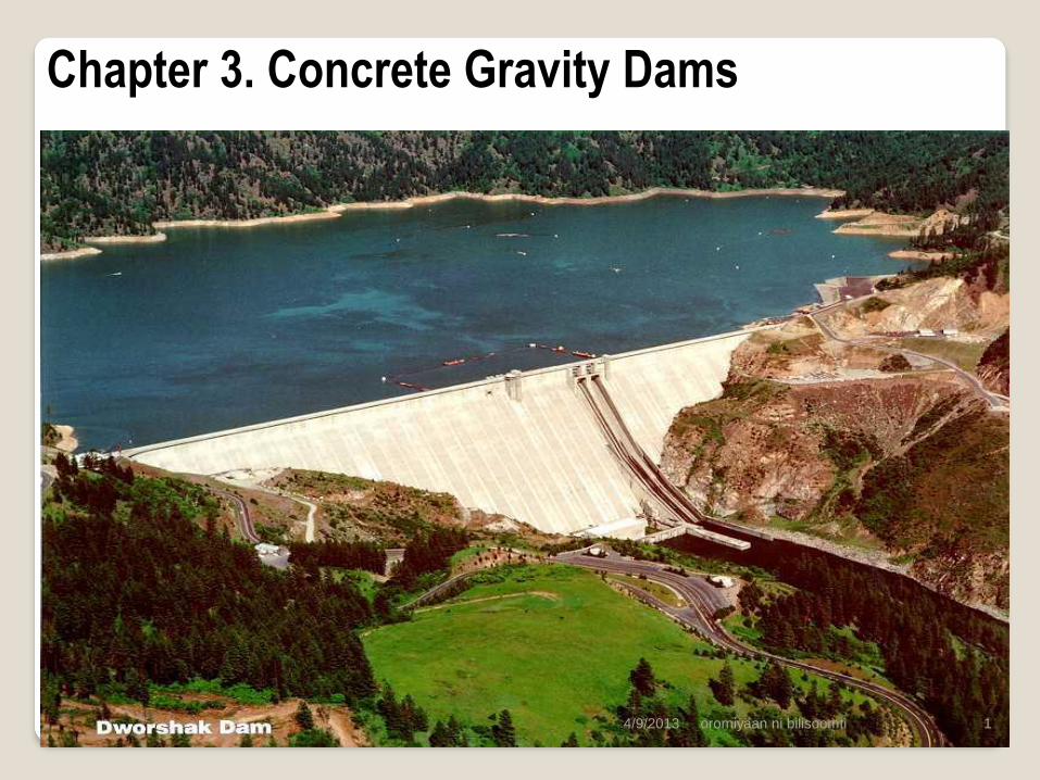
Chapter 3. Concrete Gravity Dams
oromiyaan ni bilisoomti 1 4/9/2013

3.1 Definition
A concrete gravity dam is a massive concrete structure, roughly triangular in shape,
and designed so that its weight ensures structural stability against the hydrostatic
pressure of the impounded water and other forces that may act on the dam.
Gravity dams may be classified by plan as straight gravity dams and curved gravity
dams, depending up on the axis alignment.
In the earlier periods, gravity dams were constructed from masonry. In recent years,
however, gravity dams are constructed from concrete.
Gravity dams are
permanent structures that require little maintenance
constructed to greater heights
oromiyaan ni bilisoomti
2 4/9/2013
oromiyaan ni bilisoomti 3
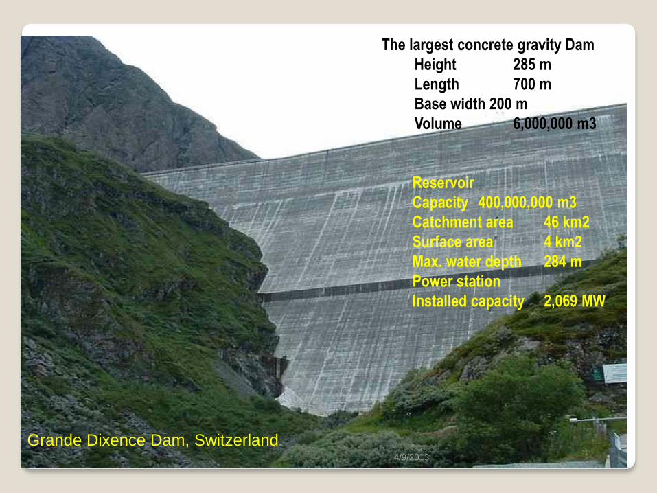
Reservoir
Capacity 400,000,000 m3
Catchment area 46 km2
Surface area 4 km2
Max. water depth 284 m
Power station
Installed capacity 2,069 MW
Grande Dixence Dam, Switzerland
The largest concrete gravity Dam
Height 285 m
Length 700 m
Base width 200 m
Volume 6,000,000 m3
4/9/2013

oromiyaan ni bilisoomti
4
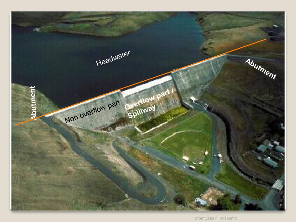
Headwater
Heel
Gallery
Outlet
Tailwater
Toe
Foundation
Crest: Top of the dam
Heel: Dam contact with foundation on the u/s side
Toe: Dam contact with foundation on the d/s side
Abutment: sides of the valley which the structure
of the dam meets
Gallery: opening or passage left in the body of
the dam for inspection and drainage purposes
Outlets: opening to discharge water
Headwater: Impounded water
4/9/2013
oromiyaan ni bilisoomti
5 4/9/2013

3.2 Types of Concrete Gravity Dams
3.2.1 Conventional Concrete Dams (CC Dams)
These are dams constructed with Mass concrete
Mass Concrete is any volume of concrete with dimensions large enough to require
that measures be taken to cope with generation of heat from hydration of the
cement and attendant volume change to minimizing cracking. (American Concrete
Institute ACI)
Cement Hydration is a very exothermic process, leading to a rise in temperature at
the core of very large pours. Expected to reach the maximum with in 1 to 3 days after
placement.
oromiyaan ni bilisoomti
6
High core temperature
during hydration
Cooled surface and
thremal cracking
if the temperature rises to 70 oc
Delayed ettringite formation (DEF) or
Ii the surface temperature is allowed to
deviate greatly from that of the core, i.e.,
temperature difference between the interior
and exterior reaches to 19 oc , thermal
cracking will develop. 4/9/2013

Cracks affects water tightness, durability, internal stresses.
Several methods for controlling cracks due to thermal stresses exist
Block construction: 15m x 15m x 1.5m
Mix design that limits heat of hydration
reduced cement content
using special low heat cement
use of pozollana and other admixtures
Embedded pipe cooling system
The main disadvantages of CC dams include
They are expensive
They require long construction time
oromiyaan ni bilisoomti
7 4/9/2013
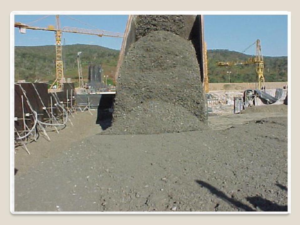
3.2.2 Roller Compacted Concrete Dams(RCC Dams)
Roller-compacted concrete is simply concrete constructed with the use of earthfill
methods. It was introduced in late 1970s
The traditional method of placing, compacting, and consolidating mass concrete is a
slow process.
Improvements in earth moving equipments made the construction of earth and rock fill
dams speedier and more cost efficient.
According to ACI,
RCC is a concrete compacted by roller compaction. The concrete, in
its unhardened state, will support a roller while being compacted
RCC thus differs from conventional concrete in its consistency requirement (zero
slump):
dry enough to support roller
wet enough to permit adequate distribution of the binder mortar during mixing
and vibration
oromiyaan ni bilisoomti
8 4/9/2013
oromiyaan ni bilisoomti 9
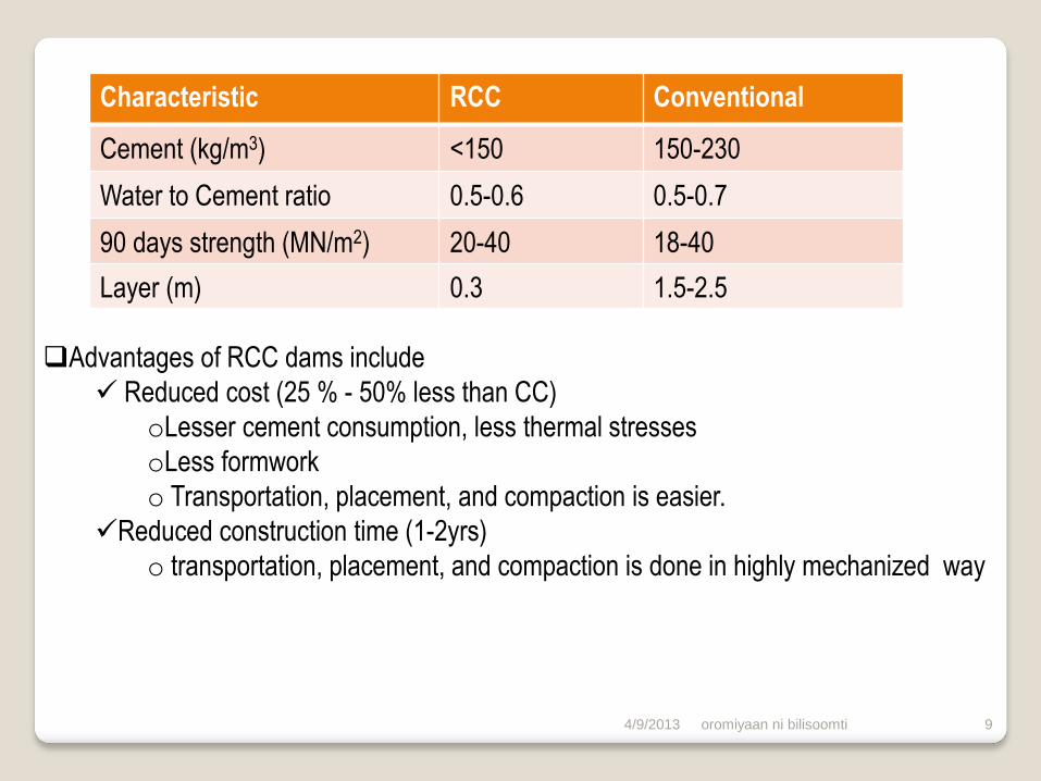
Advantages of RCC dams include
Reduced cost (25 % - 50% less than CC)
oLesser cement consumption, less thermal stresses
oLess formwork
o Transportation, placement, and compaction is easier.
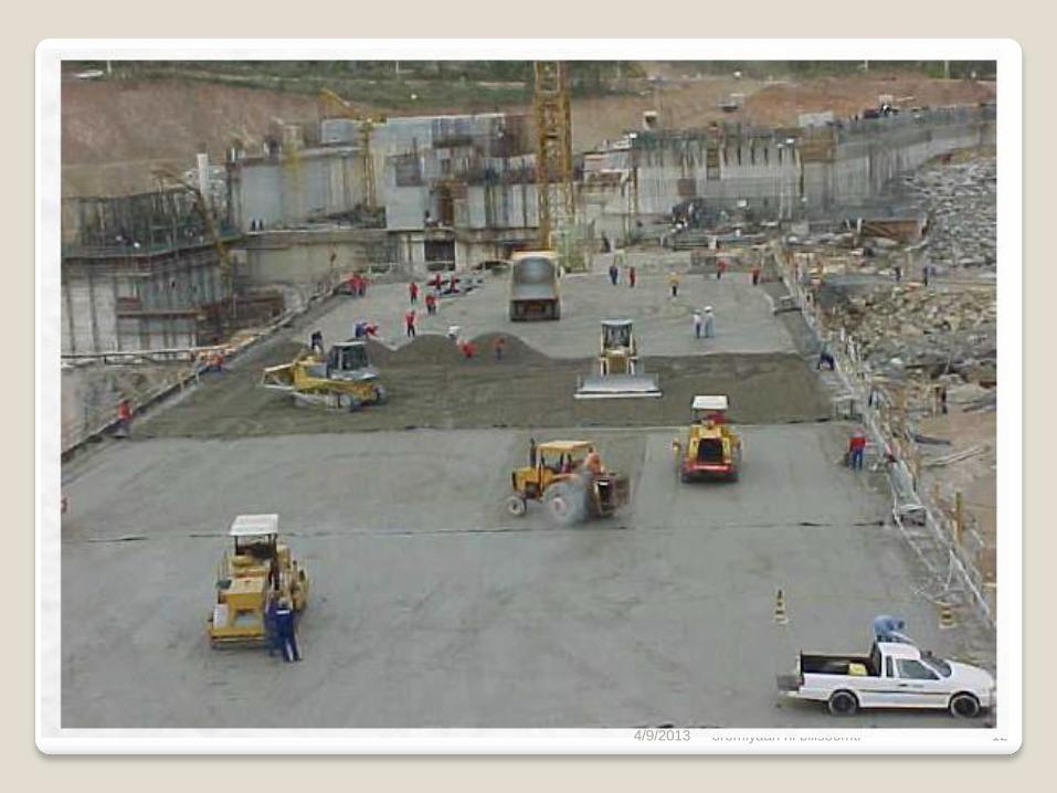
Reduced construction time (1-2yrs)
o transportation, placement, and compaction is done in highly mechanized way
Characteristic RCC Conventional
Cement (kg/m3) <150 150-230
Water to Cement ratio 0.5-0.6 0.5-0.7
90 days strength (MN/m2) 20-40 18-40
Layer (m) 0.3 1.5-2.5
4/9/2013
oromiyaan ni bilisoomti 10 4/9/2013

oromiyaan ni bilisoomti 11 4/9/2013
oromiyaan ni bilisoomti 12 4/9/2013

oromiyaan ni bilisoomti 13 4/9/2013

2.3. Loads on Gravity Dams
The structural integrity of a dam must be maintained across the range of
circumstances or events likely to arises in service. The design is therefore determined
through considerations of corresponding spectrum of loading conditions.
Gravity dams are subjected to the following main loads / forces
1. Water pressure (water load)
2. Weight of the dam
3. Uplift pressure
4. Silt pressure
5. Wave pressure
6. Ice pressure
7. Wind load
8. Earthquake load
Headwater
Tailwater
silt
P1
P1
P2
P3
P8
P6 P5
P4
oromiyaan ni bilisoomti
14
P8
4/9/2013
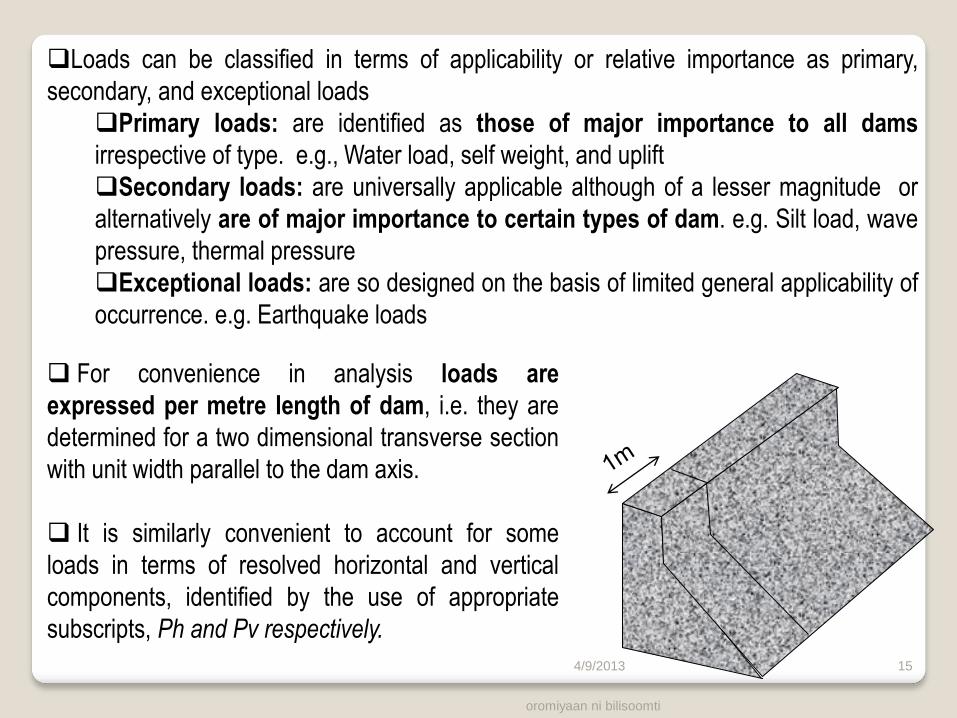
Loads can be classified in terms of applicability or relative importance as primary,
secondary, and exceptional loads
Primary loads: are identified as those of major importance to all dams
irrespective of type. e.g., Water load, self weight, and uplift
Secondary loads: are universally applicable although of a lesser magnitude or
alternatively are of major importance to certain types of dam. e.g. Silt load, wave
pressure, thermal pressure
Exceptional loads: are so designed on the basis of limited general applicability of
occurrence. e.g. Earthquake loads
oromiyaan ni bilisoomti
15
For convenience in analysis loads are
expressed per metre length of dam, i.e. they are
determined for a two dimensional transverse section
with unit width parallel to the dam axis.
It is similarly convenient to account for some
loads in terms of resolved horizontal and vertical
components, identified by the use of appropriate
subscripts, Ph and Pv respectively.
4/9/2013

2.3.1 Primary Loads
2.3.1.1 Water loads
A. Non-overflow section
PH
PH’
H
Z
PV’
H’
γw H γw H’
i) U/s vertical face
a) Upstream face: Horizontal force
The force acts horizontally at from the basis of the dam
b) Downstream face: Horizontal and vertical forces
Horizontal component
The force acts horizontally at from the basis of the dam
Vertical component d/s face
The force acts vertically at from the toe of the dam
H – Headwater depth
H’ – Tailwater depth
PH – Horizontal Headwater Pressure Force
PH ‘– Horizontal Tailwater Pressure Force
PV ‘– Vertical Tailwater Pressure Force
C
D E
oromiyaan ni bilisoomti
16 4/9/2013
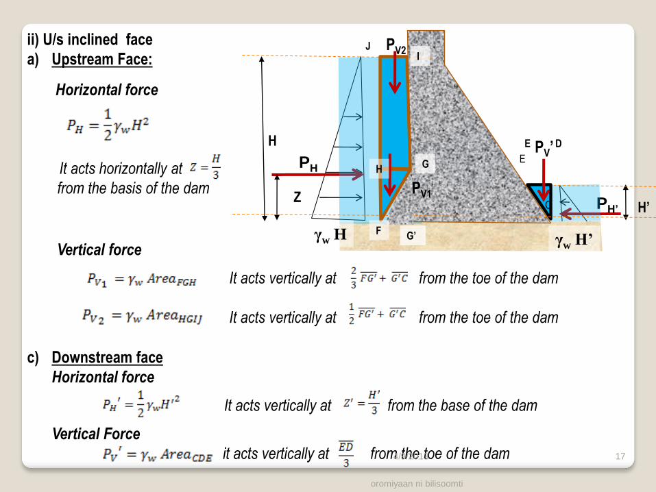
Vertical force
It acts vertically at from the toe of the dam
It acts vertically at from the toe of the dam
ii) U/s inclined face
a) Upstream Face:
Horizontal force
It acts horizontally at
from the basis of the dam
PH
PH’
H
Z
PV’
H’
γw H γw H’
c) Downstream face
Horizontal force
It acts vertically at from the base of the dam
Vertical Force
it acts vertically at from the toe of the dam
C
D
E
PV1
PV2
E
F
G H
J I
G’
oromiyaan ni bilisoomti
17 4/9/2013
oromiyaan ni bilisoomti 18
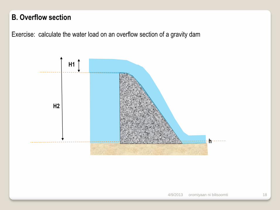
H2
H1
h
B. Overflow section
Exercise: calculate the water load on an overflow section of a gravity dam
4/9/2013
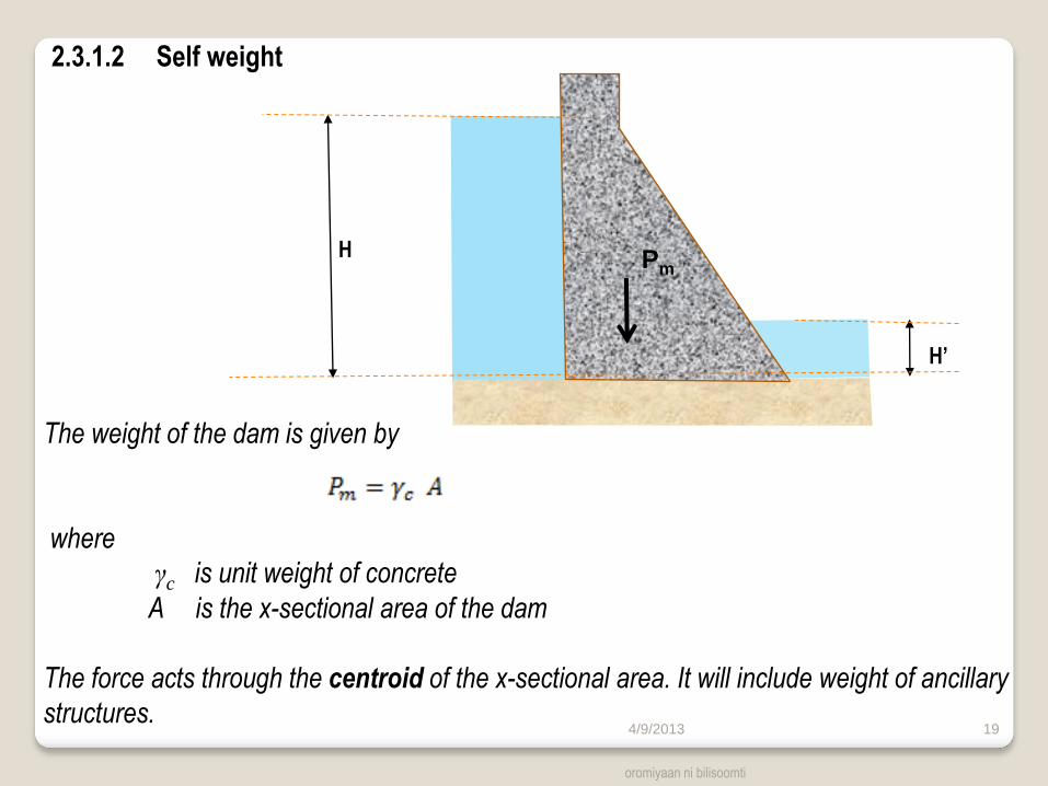
2.3.1.2 Self weight
H
H’
The weight of the dam is given by
where
γc is unit weight of concrete
A is the x-sectional area of the dam
The force acts through the centroid of the x-sectional area. It will include weight of ancillary
structures.
oromiyaan ni bilisoomti
19
Pm
4/9/2013
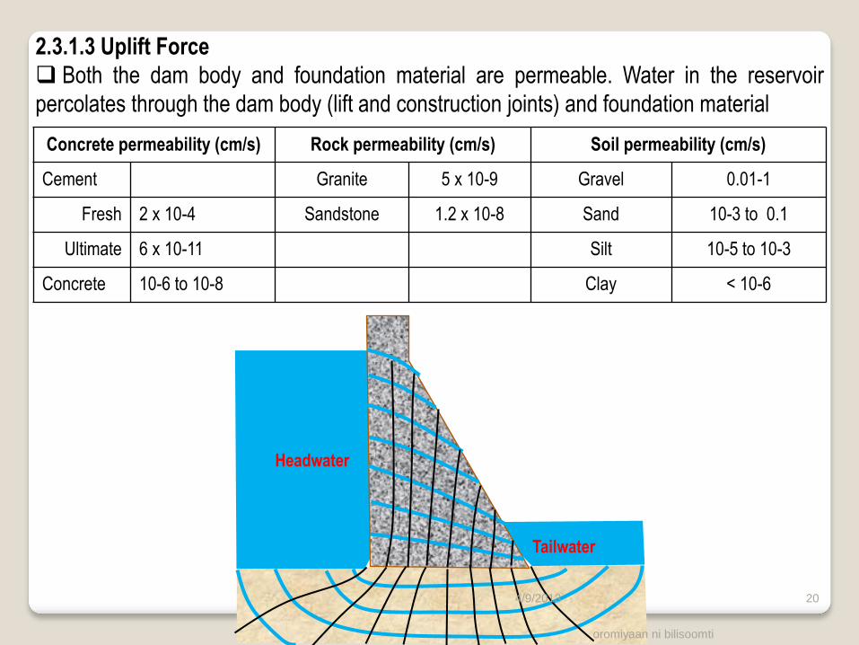
2.3.1.3 Uplift Force
Both the dam body and foundation material are permeable. Water in the reservoir
percolates through the dam body (lift and construction joints) and foundation material
Headwater
Tailwater
Concrete permeability (cm/s) Rock permeability (cm/s) Soil permeability (cm/s)
Cement Granite 5 x 10⁻⁹ Gravel 0.01-1
Fresh 2 x 10⁻⁴ Sandstone 1.2 x 10⁻⁸ Sand 10-3 to 0.1
Ultimate 6 x 10-11 Silt 10-5 to 10-3
Concrete 10-6 to 10-8 Clay < 10-6
oromiyaan ni bilisoomti
20 4/9/2013

T he percolating water exerts an uplift pressure with in the dam body and at the base
of the dam. The uplift in the dam body is small compared to at the base. The uplift force
due to the uplift pressure at the base depends on two factors
A) Area factor : the fraction of the actual area of the base over which the uplift pressure
is supposed to act. (Link)
B) Intensity factor: the intensity of pressure acting on any point of the base expressed
as a fraction of the total head Uplift at the heel = hydrostatic pressure at
the u/s headwater
Uplift at the heel = hydrostatic pressure at
the tailwater
Uplift pressure at any intermediate point =
linear interpolation
Uplift force = Average pressure intensity x
Area x Area factor (η)
It acts at from the toe
Tailwater
Pu
H
H’
B
oromiyaan ni bilisoomti
21 4/9/2013

Effects of drains on uplift pressure
To reduce uplift pressure, drains are formed through the body of the dam and also
drainage holes are drilled in the foundation rock
Uplift at the heel
Uplift at the toe
Uplift pressure at the line of drain
Hd – mean effective head at the line of drain
Kd is a function of drain geometry
The uplift force
and acts at
Tailwater
Pu
H
H’ B
a
oromiyaan ni bilisoomti 22 4/9/2013

2.3.2 Secondary Loads
2.3.2.1 Earth and Silt Load
Gravity dams are sometimes subjected to earth pressures on either u/s or d/s face,
where the foundation trench is backfilled. Such pressures usually have minor effect on
the stability of the structure, and may be ignored in design.
Practically all streams transport silts or fine sediments, particularly during floods. The
gradual accumulation of fine sediments against the face of the dam generates a
resultant horizontal force Psh. The magnitudes of Psh, which is in addition to the water load,
is a function of the sediment depth, hs, the submerged unit weight, γ’s , and the active
lateral pressure coefficient Ks. When the u/s face have flaring, the sediments will generate
vertical force Psv.
Psh
Psv
Psh hs oromiyaan ni bilisoomti
23 4/9/2013
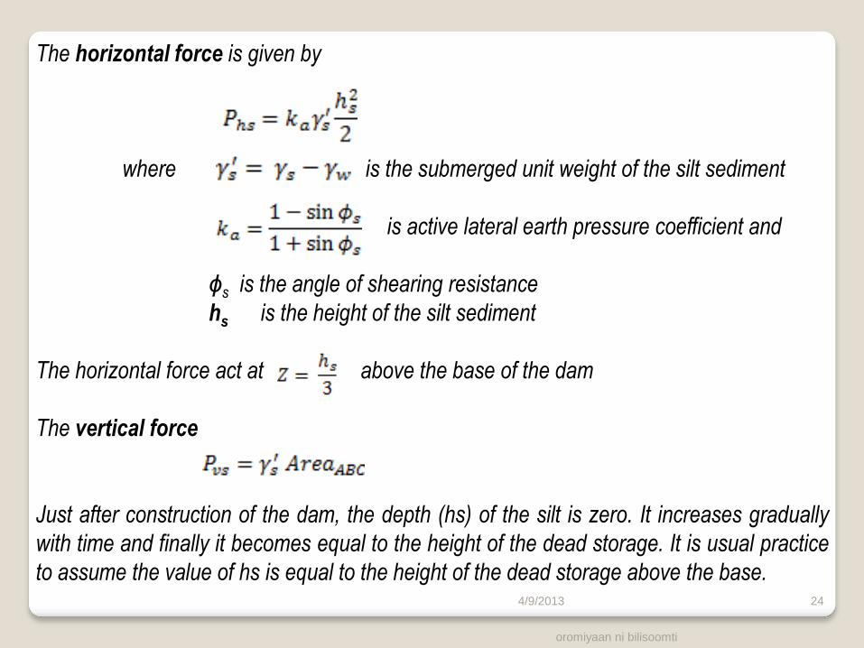
The horizontal force is given by
where is the submerged unit weight of the silt sediment
is active lateral earth pressure coefficient and
ϕs is the angle of shearing resistance
hs is the height of the silt sediment
The horizontal force act at above the base of the dam
The vertical force
Just after construction of the dam, the depth (hs) of the silt is zero. It increases gradually
with time and finally it becomes equal to the height of the dead storage. It is usual practice
to assume the value of hs is equal to the height of the dead storage above the base.
oromiyaan ni bilisoomti
24 4/9/2013
oromiyaan ni bilisoomti
25
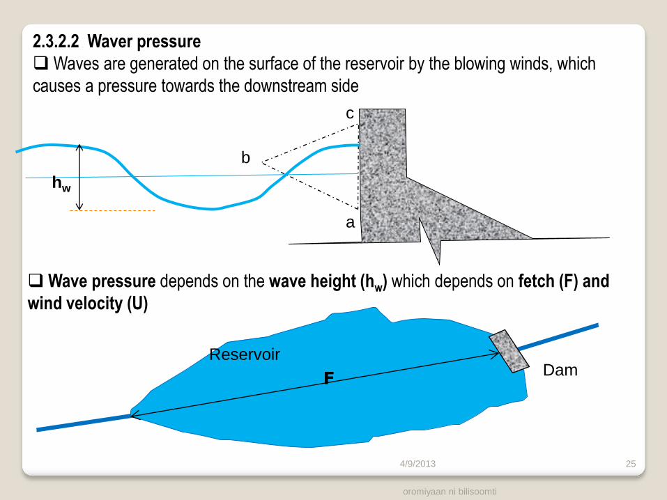
2.3.2.2 Waver pressure
Waves are generated on the surface of the reservoir by the blowing winds, which
causes a pressure towards the downstream side
Wave pressure depends on the wave height (hw) which depends on fetch (F) and
wind velocity (U)
a
c
b
hw
F Dam
Reservoir
4/9/2013
oromiyaan ni bilisoomti
26
a
c
b
hw
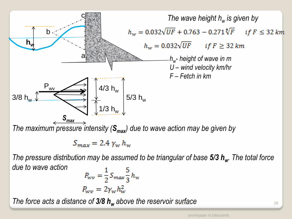
The wave height hw is given by
hw- height of wave in m
U – wind velocity km/hr
F – Fetch in km
The maximum pressure intensity (Smax) due to wave action may be given by
The pressure distribution may be assumed to be triangular of base 5/3 hw. The total force
due to wave action
The force acts a distance of 3/8 hw above the reservoir surface
5/3 hw
1/3 hw
4/3 hw Pwv
3/8 hw
Smax
4/9/2013

oromiyaan ni bilisoomti 27
2.3.3 Exceptional loads
2.3.3.1 Earth quake forces
Earthquake represents the release of built up stress in the lithosphere. It occurs
along fault lines. The released energy propagates in form of seismic waves that causes
the ground to shake. Earthquake link
Ground motions associated with earthquakes can be characterized in terms of
acceleration. The earthquake ground acceleration are expressed as fraction of
gravitational acceleration.
ground acceleration = αg
Although the seismic waves propagate in all direction, for design purpose, the
accelerations are resolved in horizontal and vertical components.
Horizontal acceleration = αh g
Vertical acceleration = αv g
Earthquake Seismic
waves Ground Motion
Equivalent to imparting
acceleration to the
ground in direction of
the wave
4/9/2013
oromiyaan ni bilisoomti 28
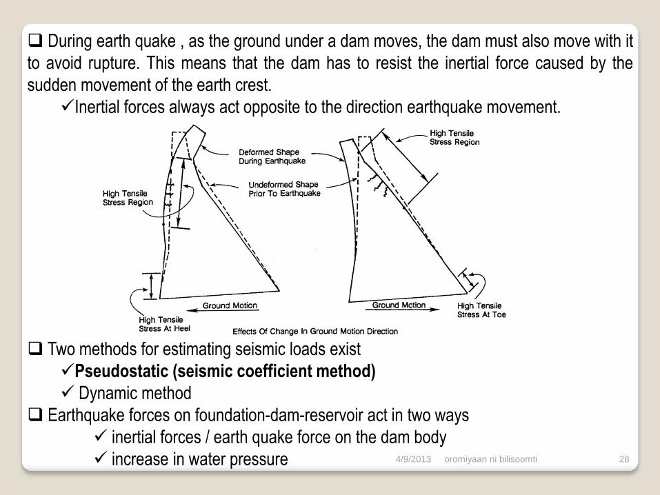
During earth quake , as the ground under a dam moves, the dam must also move with it
to avoid rupture. This means that the dam has to resist the inertial force caused by the
sudden movement of the earth crest.
Inertial forces always act opposite to the direction earthquake movement.
Two methods for estimating seismic loads exist
Pseudostatic (seismic coefficient method)
Dynamic method
Earthquake forces on foundation-dam-reservoir act in two ways
inertial forces / earth quake force on the dam body
increase in water pressure
4/9/2013
oromiyaan ni bilisoomti
29
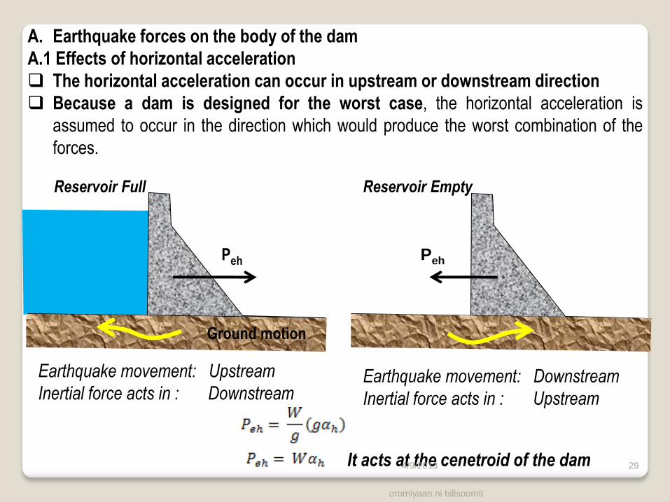
A. Earthquake forces on the body of the dam
A.1 Effects of horizontal acceleration
The horizontal acceleration can occur in upstream or downstream direction
Because a dam is designed for the worst case, the horizontal acceleration is
assumed to occur in the direction which would produce the worst combination of the
forces.
Reservoir Empty
Earthquake movement: Upstream
Inertial force acts in : Downstream
Ground motion
Reservoir Full
Peh Peh
Earthquake movement: Downstream
Inertial force acts in : Upstream
It acts at the cenetroid of the dam 4/9/2013
oromiyaan ni bilisoomti
30
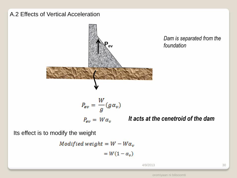
Pev
A.2 Effects of Vertical Acceleration
It acts at the cenetroid of the dam
Its effect is to modify the weight
Dam is separated from the
foundation
4/9/2013

oromiyaan ni bilisoomti
31
B. Earthquake forces on the body of water
B.1 Effects of horizontal acceleration
Dam and foundation move in upstream direction, they push against the reservoir
momentarily increasing the water pressure
An initial estimate of these forces can be obtained using a parabolic approximation to the
theoretical pressure distribution as analysed in Westergaard (1933). Relative to any
elevation at depth Z below the water surface, hydrodynamic pressure pewh is determined by
Ground motion
where
zmax is the maximum depth of water at the section of dam considered
Ce is a dimensionless pressure factor, and is a function of Z/Zmax and ϴ, the angle of
inclination of the upstream face to the vertical.
.
Zmax
Z
4/9/2013

oromiyaan ni bilisoomti
32
The resultant hydrodynamic load is given by
And the load acts at 0.4 Z
B. Effect of vertical acceleration
If the dam has an upstream flare / batter the resultant vertical hydrodynamic load, Pewv,
effective above an upstream face batter or flare may be accounted for by application of the
appropriate seismic coefficient to vertical water load, Pwv. It is considered to act through the
centroid of area thus:
ϴ, the angle of inclination of the upstream face to the vertical.
4/9/2013

oromiyaan ni bilisoomti
33
2.3.4 Load Combinations
All the forces which are discussed in the preceding sections may not act simultaneously on a dam.
A concrete dam should be designed with regard to the most rigorous adverse groupings or
combination of load which gave a reasonable probability of simultaneous occurrence.
Three nominated load combinations are sufficient for almost all circumstances. In ascending
order of severity they may be designated as normal (sometimes usual), unusual and extreme load
combinations, here denoted as NLC, ULC and ELC respectively,
Load source Qualification Load combination
NLC ULC ELC
Primary
1. Headwater At Design Flood Level (MWL) X
At Full Reservoir Level (FRL) X X
2. Tail Water At maximum tail water level X X
Minimum tail water level X
3. Self weight - X X X
4. Uplift Drains functioning X X
Drains inoperative X* X* X
Secondary 5. Silt - X X X
Exceptional Seismic - X 4/9/2013

oromiyaan ni bilisoomti
34
The Indian Standard Criteria (IS: 6512-1972) :
Load Combination Load
A. – Const Condition Dam completed but no water in reservoir and no tail water.
B – Normal Operating
Condition
Full reservoir elevation, normal dry weather tail water,
normal uplift, ice and silt (if applicable).
C – Flood Discharge
Condition
Reservoir at maximum flood elevation, all gates open, tail
water at flood elevation, normal uplift and silt (if applicable).
D Combination A with earthquake.
E Combination B with earthquake.
F Combination C, but with extreme uplift.
G Combination E, but with extreme uplift.
4/9/2013
oromiyaan ni bilisoomti
35
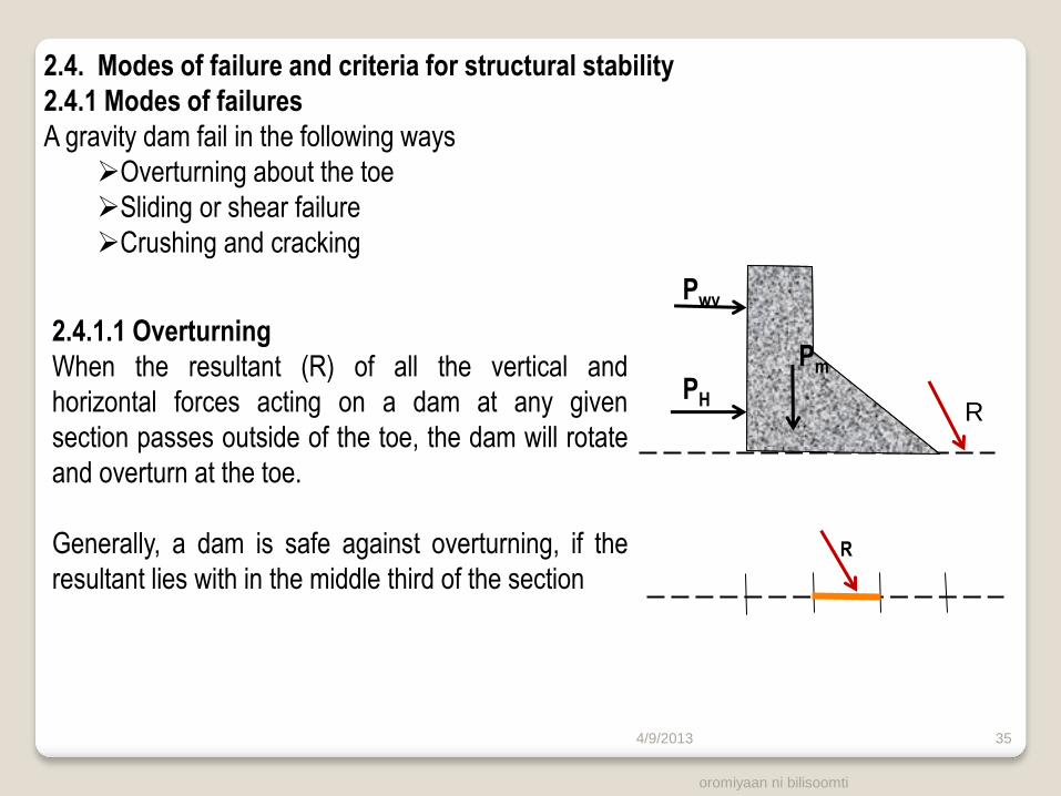
2.4. Modes of failure and criteria for structural stability
2.4.1 Modes of failures
A gravity dam fail in the following ways
Overturning about the toe
Sliding or shear failure
Crushing and cracking
2.4.1.1 Overturning
When the resultant (R) of all the vertical and
horizontal forces acting on a dam at any given
section passes outside of the toe, the dam will rotate
and overturn at the toe.
Generally, a dam is safe against overturning, if the
resultant lies with in the middle third of the section
R
Pwv
PH
Pm
R
4/9/2013
oromiyaan ni bilisoomti
36
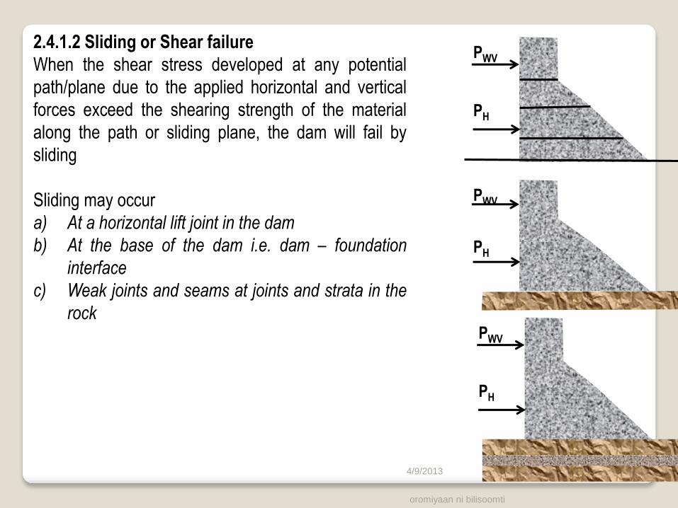
2.4.1.2 Sliding or Shear failure
When the shear stress developed at any potential
path/plane due to the applied horizontal and vertical
forces exceed the shearing strength of the material
along the path or sliding plane, the dam will fail by
sliding
Sliding may occur
a) At a horizontal lift joint in the dam
b) At the base of the dam i.e. dam – foundation
interface
c) Weak joints and seams at joints and strata in the
rock
PWV
PH
PWV
PH
PWV
PH
4/9/2013
oromiyaan ni bilisoomti 37
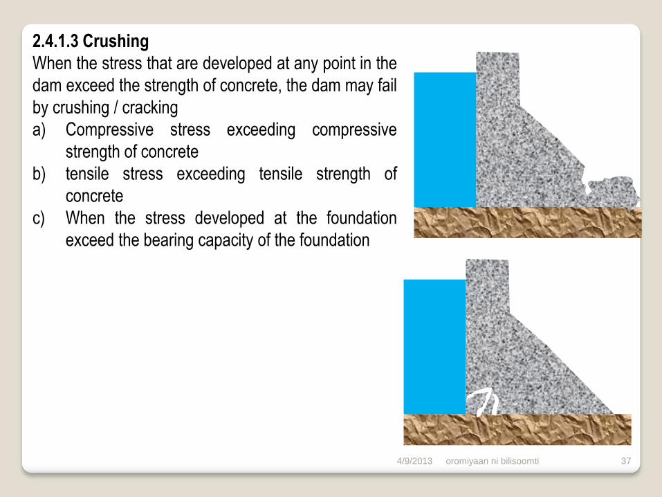
2.4.1.3 Crushing
When the stress that are developed at any point in the
dam exceed the strength of concrete, the dam may fail
by crushing / cracking
a) Compressive stress exceeding compressive
strength of concrete
b) tensile stress exceeding tensile strength of
concrete
c) When the stress developed at the foundation
exceed the bearing capacity of the foundation
4/9/2013
oromiyaan ni bilisoomti
38
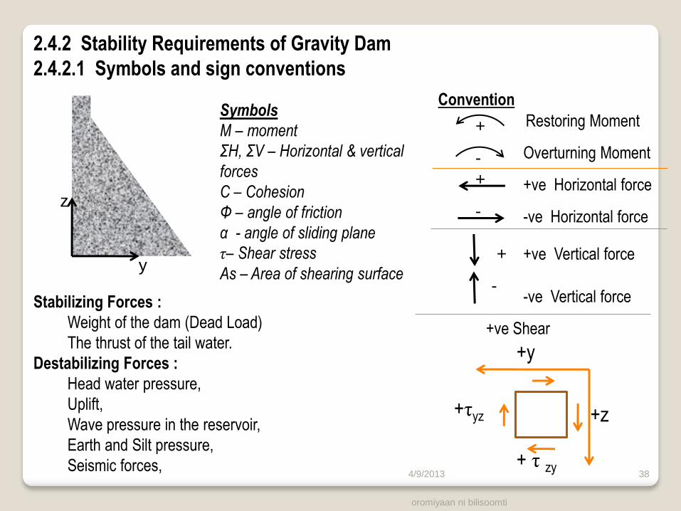
2.4.2 Stability Requirements of Gravity Dam
2.4.2.1 Symbols and sign conventions
y
z
Symbols
M – moment
ΣH, ΣV – Horizontal & vertical
forces
C – Cohesion
Φ – angle of friction
α - angle of sliding plane
τ– Shear stress
As – Area of shearing surface
Convention
Restoring Moment
Overturning Moment
+ve Horizontal force
-ve Horizontal force
+ve Vertical force
-ve Vertical force
+
-
+
+
-
-
+y
+z +τyz
+ τ zy
Stabilizing Forces :
Weight of the dam (Dead Load)
The thrust of the tail water.
Destabilizing Forces :
Head water pressure,
Uplift,
Wave pressure in the reservoir,
Earth and Silt pressure,
Seismic forces,
+ve Shear
4/9/2013

oromiyaan ni bilisoomti
39
2.4.2.2. Structural Equilibrium
Applied Force = Reactive Force
ΣM = 0 No rotational movement ΣFx = 0 No translational movement
ΣFy = 0
Pwv
R
PH
PU
Pm
Phs
PV’
PH’
R’
R = Resultant of all loads R’ = Foundation Reaction
4/9/2013

oromiyaan ni bilisoomti 40
2.4.2.3 Assumptions in Stability Analysis
1. Concrete used homogeneous, isotropic and elastic
2. Dam consist of a number of vertical cantilivers of unit length. The cantilevers act
independently
3. Perfect bond between dam and foundation
4. All loads are transferred by cantilever action by the foundation. No beam action
5. The foundation is strong and unyielding. No movement caused in the foundation due
to the imposed loads
6. Small openings, galleries, shafts, do not affect the over all stability.
4/9/2013

oromiyaan ni bilisoomti 41
2.4.2.4 Stability Requirements
A gravity dam must be designed such that it is safe against all possible modes of
failures, with adequate factor of safety. A dam may fail
a. Overturning
b. Sliding and shear
c. Crushing
2.4.2.5 Overturning Stability (Fo)
The moments are about the toe of any horizontal plane
ΣM-ve includes the moment generated by uplift.
+
-
Criteria
Fo > 1.25 Acceptable
Fo > 1.50 Desirable
4/9/2013
oromiyaan ni bilisoomti
42
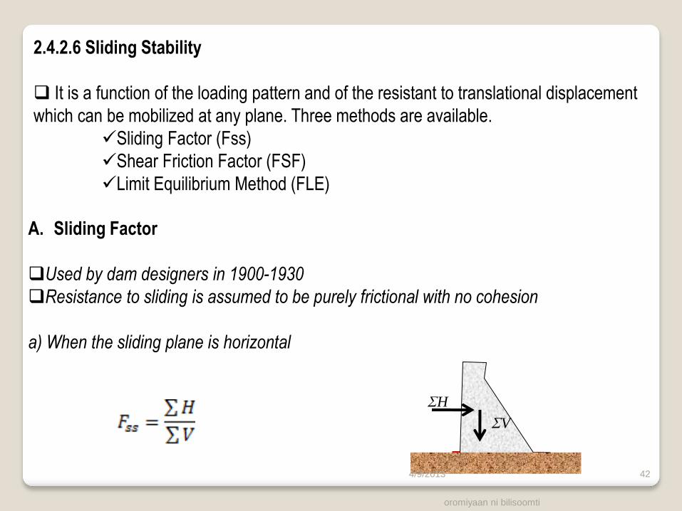
2.4.2.6 Sliding Stability
It is a function of the loading pattern and of the resistant to translational displacement
which can be mobilized at any plane. Three methods are available.
Sliding Factor (Fss)
Shear Friction Factor (FSF)
Limit Equilibrium Method (FLE)
A. Sliding Factor
Used by dam designers in 1900-1930
Resistance to sliding is assumed to be purely frictional with no cohesion
a) When the sliding plane is horizontal
ΣH
ΣV
4/9/2013
oromiyaan ni bilisoomti 43
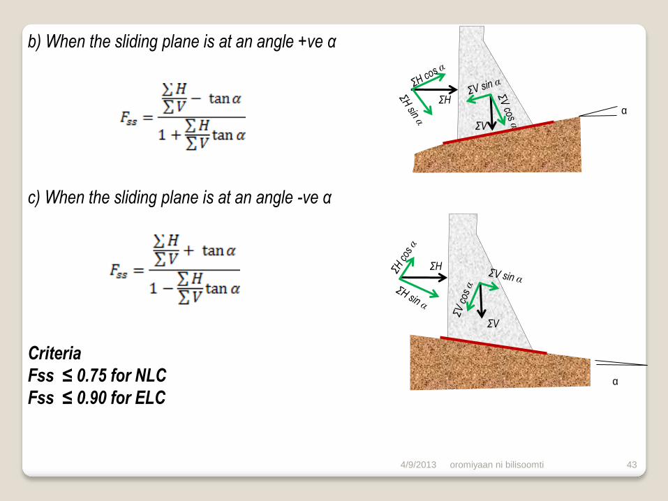
b) When the sliding plane is at an angle +ve α
c) When the sliding plane is at an angle -ve α
Criteria
Fss ≤ 0.75 for NLC
Fss ≤ 0.90 for ELC
ΣH
ΣV
α
ΣH
ΣV
α
4/9/2013
oromiyaan ni bilisoomti
44
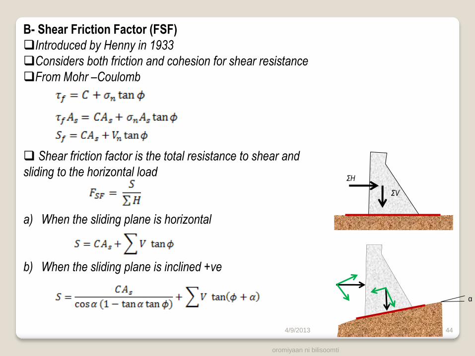
B- Shear Friction Factor (FSF)
Introduced by Henny in 1933
Considers both friction and cohesion for shear resistance
From Mohr –Coulomb
Shear friction factor is the total resistance to shear and
sliding to the horizontal load
a) When the sliding plane is horizontal
b) When the sliding plane is inclined +ve
ΣH
ΣV
α
4/9/2013
oromiyaan ni bilisoomti 45
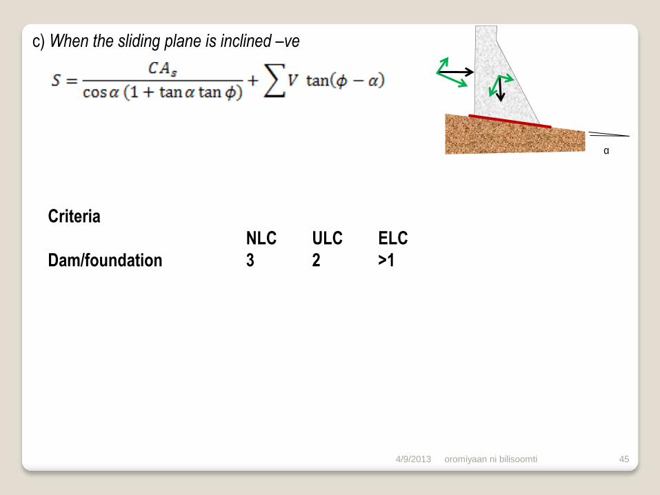
c) When the sliding plane is inclined –ve
Criteria
NLC ULC ELC
Dam/foundation 3 2 >1
α
4/9/2013

oromiyaan ni bilisoomti
46
C) Limit equilibrium Factor (FLE)
It follows the conventional soil mechanics logic
τa is the shear strength available
τ shear stress developed under the applied loading
τa is expressed by mohr-coulomb failure criteria
a) When the sliding plane is horizontal
b) When the sliding plane is inclined at an angle +ve α
c) When the sliding plane is inclined at angle –ve α
Criteria
FLE = 2 NLC
FLE = 1.3 ELC
4/9/2013

oromiyaan ni bilisoomti 47
3.4.2.7 Stress Analysis
Gravity method is commonly used
2d elastic dam on rigid foundation
stress evaluated in the analysis
The various stresses that are determined in gravity method are
1. Vertical normal stress, σz , on horizontal planes;
2. Horizontal normal stress, σy , on vertical planes;
3. Horizontal and vertical shear stresses τZy & τyz;
4. Principal stresses σ1 & σ3;
+z σz
σz
σy σ1
τyz
τzy
τzy
τyz
σy
+y
4/9/2013
oromiyaan ni bilisoomti 48
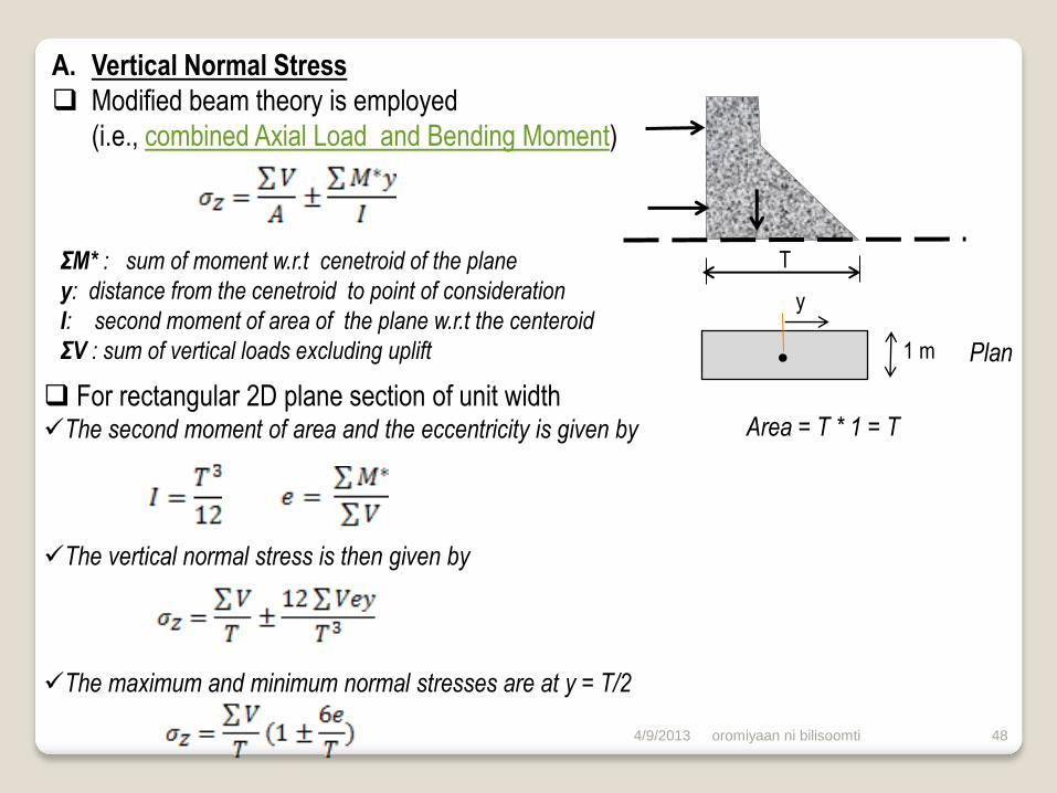
A. Vertical Normal Stress
Modified beam theory is employed
(i.e., combined Axial Load and Bending Moment)
T
1 m
y
Area = T * 1 = T
ΣM* : sum of moment w.r.t cenetroid of the plane
y: distance from the cenetroid to point of consideration
I: second moment of area of the plane w.r.t the centeroid
ΣV : sum of vertical loads excluding uplift
For rectangular 2D plane section of unit width The second moment of area and the eccentricity is given by
The vertical normal stress is then given by
The maximum and minimum normal stresses are at y = T/2
Plan
4/9/2013

A.2 For reservoir empty condition
U/s face
D/s face
oromiyaan ni bilisoomti
49
A.1 For reservoir full condition
U/s face
D/s face R
σzu σzd
R
σzd σzu
For e > T/6; -ve stress develop at u/s face, i.e., Tensile stress
4/9/2013

oromiyaan ni bilisoomti 50
B. Shear Stresses
Linearly varying normal stress generate
numerically equal and complementary
τyz horizontal shear
τzy vertical shear
Adequate to establish the shear stresses
at the boundary
Taking a small element on the u/s and d/s
faces: link
U/s face
D/s face
4/9/2013

oromiyaan ni bilisoomti 51
C. Horizontal Normal Stress
Horizontal normal stress on vertical
planes can be determined from
consideration of horizontal shear forces.
Differences in horizontal shear forces is
balanced by normal stresses on vertical
planes
U/s
D/s
4/9/2013
oromiyaan ni bilisoomti 52
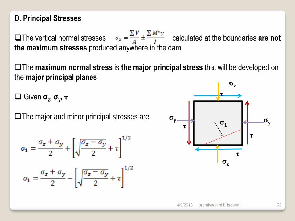
D. Principal Stresses
The vertical normal stresses calculated at the boundaries are not
the maximum stresses produced anywhere in the dam.
The maximum normal stress is the major principal stress that will be developed on
the major principal planes
Given σz, σy, τ
The major and minor principal stresses are σy
σz
σz
σy σ1 τ
τ
τ
τ
4/9/2013

oromiyaan ni bilisoomti 53
The upstream and downstream faces are places of zero shear, and therefore planes of
principal stresses. Link. The boundary values of σ1 & σ3 are then determined as follows:
For U/S face
For D/s face assuming no tail water
Criteria
Concrete Rock
NLC 3 4
ULC 2 2.7
ELC 1 1.3 4/9/2013