chapter 3 · this chapter contains the engineering properties and related characteristics of...
TRANSCRIPT

MIL-HDBK-5H1 December 1998
3-1
����� ��� ��� ����������� ��� ������� ��� ���� �������� �������������� � ���� !
AlloyGroup Major Alloying Elements
AlloyGroup Major Alloying Groups
Wrought Alloys Cast Alloys
1XXX
2XXX3XXX4XXX5XXX6XXX7XXX8XXX9XXX
99.00 percent minimum aluminumCopperManganeseSiliconMagnesiumMagnesium and SiliconZincOther ElementsUnused Series
1XX.0
2XX.03XX.04XX.05XX.06XX.07XX.08XX.09XX.0
99.00 percent minimum aluminum
CopperSilicon with added copper and/or magnesiumSiliconMagnesiumUnused SeriesZincTinOther Elements
��������
�� ������
This chapter contains the engineering properties and related characteristics of wrought and castaluminum alloys used in aircraft and missile structural applications.
General comments on engineering properties and the considerations relating to alloy selection arepresented in Section 3.1. Mechanical and physical property data and characteristics pertinent to specificalloy groups or individual alloys are reported in Sections 3.2 through 3.10. Element properties are pre-sented in Section 3.11.
Aluminum is a lightweight, corrosion-resistant structural material that can be strengthened throughalloying and, dependent upon composition, further strengthened by heat treatment and/or cold working[Reference 3.1(a)]. Among its advantages for specific applications are: low density, high strength-to-weight ratio, good corrosion resistance, ease of fabrication and diversity of form.
Wrought and cast aluminum and aluminum alloys are identified by a four-digit numericaldesignation, the first digit of which indicates the alloy group as shown in Table 3.1. For structural wroughtaluminum alloys the last two digits identify the aluminum alloy. The second digit indicates modificationsof the original alloy or impurity limits. For cast aluminum and aluminum alloys the second and third digitsidentify the aluminum alloy or indicate the minimum aluminum percentage. The last digit, which is to theright of the decimal point, indicates the product form: XXX.0 indicates castings, and XXX.1 and XXX.2indicate ingot.
CHAPTER 3

MIL-HDBK-5H1 December 1998
3-2
����� ���� �������� ����� "���#
Section Alloy DesignationSec-tion Alloy Designation
3.23.2.13.2.23.2.33.2.43.2.53.2.63.2.73.2.83.2.93.33.43.53.5.13.5.23.5.33.5.43.5.53.63.6.13.6.2
2000 series wrought alloys2014210720242025209021242219251926183000 series wrought alloys4000 series wrought alloys5000 series wrought alloys505250835086545454566000 series wrought alloys60136061
3.6.33.73.7.13.7.23.7.33.7.43.7.53.7.63.7.73.7.83.83.8.13.93.9.13.9.23.9.33.9.43.9.53.9.63.9.73.9.8
61517000 series wrought alloys70107049/7149705070757150717572497475200.0 series cast alloysA201.0300.0 series cast alloys354.0355.0C355.0356.0A356.0A357.0D357.0359.0
����� �������� ����� ��� — The layout of this chapter is in accordance with this four-digit number system for both wrought and cast alloys [Reference 3.1(b)]. Table 3.1.1 is the aluminum alloyindex that illustrates both the general section layout as well as details of those specific aluminum alloyspresently contained in this chapter. The wrought alloys are in Sections 3.2 through 3.7; whereas the castalloys are in Sections 3.8 and 3.9.
����� �� ���� ���� �� — The properties of the aluminum alloys are determined by thealloy content and method of fabrication. Some alloys are strengthened principally by cold work, whileothers are strengthened principally by solution heat treatment and precipitation hardening [Reference3.1(a)]. The temper designations, shown in Table 3.1.2 (which is based on Reference 3.1.2), are indicativeof the type of strengthening mechanism employed.
Among the properties presented herein, some, such as the room-temperature, tensile, compressive,shear and bearing properties, are either specified minimum properties or derived minimum propertiesrelated directly to the specified minimum properties. They may be directly useful in design. Data on theeffect of temperature on properties are presented so that percentages may be applied directly to the room-temperature minimum properties. Other properties, such as the stress-strain curve, fatigue and fracturetoughness data, and modulus of elasticity values, are presented as average or typical values, which may beused in assessing the usefulness of the material for certain applications. Comments on the effect oftemperature on properties are given in Sections 3.1.2.1.7 and 3.1.2.1.8; comments on the corrosion resis-tance are given in Section 3.1.2.3; and comments on the effects of manufacturing practices on these proper-ties are given in Section 3.1.3.

MIL-HDBK-5H1 December 1998
3-3
����� ���$� ���%�� ����������� &����� ��� �������� ������
Temper Designation Systemab
The temper designation system is used for allforms of wrought and cast aluminum and aluminumalloys except ingot. It is based on the sequences ofbasic treatments used to produce the various tem-pers. The temper designation follows the alloydesignation, the two being separated by a hyphen.Basic temper designations consist of letters. Sub-divisions of the basic tempers, where required, areindicated by one or more digits following the letter.These designate specific sequences of basic treat-ments, but only operations recognized as signifi-cantly influencing the characteristics of the productare indicated. Should some other variation of thesame sequence of basic operations be applied to thesame alloy, resulting in different characteristics, thenadditional digits are added to the designation.
Basic Temper Designations
F as fabricated. Applies to the products of shap-ing processes in which no special control overthermal conditions or strain-hardening isemployed. For wrought products, there are nomechanical property limits.
O annealed. Applies to wrought products whichare annealed to obtain the lowest strength temper,and to cast products which are annealed toimprove ductility and dimensional stability. TheO may be followed by a digit other than zero.
H strain-hardened (wrought products only).Applies to products which have their strengthincreased by strain-hardening, with or withoutsupplementary thermal treatments to producesome reduction in strength. The H is alwaysfollowed by two or more digits.
W solution heat-treated. An unstable temperapplicable only to alloys which spontaneouslyage at room temperature after solution heat-treatment. This designation is specific only when
the period of natural aging is indicated: forexample, W ½ hr.
T thermally treated to produce stable tempersother than F, O, or H. Applies to productswhich are thermally treated, with or withoutsupplementary strain-hardening, to producestable tempers. The T is always followed by oneor more digits.
Subdivisions of H Temper: Strain-hardened.
The first digit following H indicates the specificcombination of basic operations, as follows:
H1 strain-hardened only. Applies to productswhich are strain-hardened to obtain the desiredstrength without supplementary thermal treat-ment. The number following this designationindicates the degree of strain-hardening.
H2 strain-hardened and partially annealed.Applies to products which are strain-hardenedmore than the desired final amount and thenreduced in strength to the desired level by partialannealing. For alloys that age-soften at roomtemperature, the H2 tempers have the sameminimum ultimate tensile strength as thecorresponding H3 tempers. For other alloys, theH2 tempers have the same minimum ultimatetensile strength as the corresponding H1 tempersand slightly higher elongation. The numberfollowing this designation indicates the degreeof strain-hardening remaining after the producthas been partially annealed.
H3 strain-hardened and stabilized. Applies toproducts which are strain-hardened and whosemechanical properties are stabilized either by alow temperature thermal treatment or as a result
a From reference 3.1.2.b Temper designations conforming to this standard for wrought aluminum and wrought aluminum alloys, and aluminum alloy
castings may be registered with the Aluminum Association provided: (1) the temper is used or is available for use by more thanone user, (2) mechanical property limits are registered, (3) characteristics of the temper are significantly different from those ofall other tempers which have the same sequence of basic treatments and for which designations already have been assigned forthe same alloy and product, and (4) the following are also registered if characteristics other than mechanical properties areconsidered significant: (a) test methods and limits for the characteristics or (b) the specific practices used to produce the temper.

MIL-HDBK-5H1 December 1998
3-4
����� ���$� ���%�� ����������� &����� ��� �������� ������ ' ���������
of heat introduced during fabrication.Stabilization usually improves ductility. Thisdesignation is applicable only to those alloyswhich, unless stabilized, gradually age-soften atroom temperature. The number following thisdesignation indicates the degree of strain-hardening remaining after the stabilizationtreatment.
The digit following the designations H1, H2, andH3 indicates the degree of strain hardening. Nu-meral 8 has been assigned to indicate tempers havingan ultimate tensile strength equivalent to thatachieved by a cold reduction (temperature duringreduction not to exceed 120�F) of approximately75 percent following a full anneal. Tempers betweenO (annealed) and 8 are designated by numerals 1through 7. Material having an ultimate tensilestrength about midway between that of the O temperand that of the 8 temper is designated by the numeral4; about midway between the O and 4 tempers by thenumeral 2; and about midway between 4 and 8tempers by the numeral 6. Numeral 9 designatestempers whose minimum ultimate tensile strengthexceeds that of the 8 temper by 2.0 ksi or more. Fortwo-digit H tempers whose second digit is odd, thestandard limits for ultimate tensile strength areexactly midway between those of the adjacent twodigit H tempers whose second digits are even.
NOTE: For alloys which cannot be cold reduced anamount sufficient to establish an ultimate tensilestrength applicable to the 8 temper (75 percent coldreduction after full anneal), the 6 temper tensilestrength may be established by a cold reduction ofapproximately 55 percent following a full anneal, orthe 4 temper tensile strength may be established by acold reduction of approximately 35 percent after afull anneal.
The third digitc, when used, indicates a variation ofa two-digit temper. It is used when the degree ofcontrol of temper or the mechanical properties orboth differ from, but are close to, that (or those) forthe two-digit H temper designation to which it is
added, or when some other characteristic issignificantly affected.
NOTE: The minimum ultimate tensile strength of athree-digit H temper must be at least as close to thatof the corresponding two-digit H temper as it is tothe adjacent two-digit H tempers. Products of the Htemper whose mechanical properties are below H_1shall be variations of H_1.
Three-digit H Tempers
H_11 Applies to products which incur sufficientstrain hardening after the final anneal thatthey fail to qualify as annealed but not somuch or so consistent an amount of strainhardening that they qualify as H_1.
H112 Applies to products which may acquire sometemper from working at an elevatedtemperature and for which there are me-chanical property limits.
Subdivisions of T Temper:Thermally Treated
Numerals 1 through 10 following the T indicatespecific sequences of basic treatments, as follows.d
T1 cooled from an elevated temperature shapingprocess and naturally aged to a substantiallystable condition. Applies to products which arenot cold worked after cooling from an elevatedtemperature shaping process, or in which theeffect of cold work in flattening or straighteningmay not be recognized in mechanical propertylimits.
T2 cooled from an elevated temperature shapingprocess, cold worked and naturally aged to asubstantially stable condition. Applies toproducts which are cold worked to improvestrength after cooling from an elevated temper-ature shaping process, or in which the effect of
c Numerals 1 through 9 may be arbitrarily assigned as the third digit and registered with The Aluminum Association for an alloyand product to indicate a variation of a two-digit H temper (see footnote b).
d A period of natural aging at room temperature may occur between or after the operations listed for the T tempers. Control of thisperiod is exercised when it is metallurgically important.
MIL-HDBK-5H1 December 1998
3-5
����� ���$� ���%�� ����������� &����� ��� �������� ������ ' ���������
cold work in flattening or straightening isrecognized in mechanical property limits.
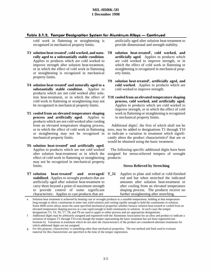
T3 solution heat-treatede, cold worked, and natu-rally aged to a substantially stable condition.Applies to products which are cold worked toimprove strength after solution heat-treatment,or in which the effect of cold work in flatteningor straightening is recognized in mechanicalproperty limits.
T4 solution heat-treatede and naturally aged to asubstantially stable condition. Applies toproducts which are not cold worked after solu-tion heat-treatment, or in which the effect ofcold work in flattening or straightening may notbe recognized in mechanical property limits.
T5 cooled from an elevated temperature shapingprocess and artificially aged. Applies toproducts which are not cold worked after coolingfrom an elevated temperature shaping process,or in which the effect of cold work in flatteningor straightening may not be recognized inmechanical property limits.
T6 solution heat-treatede and artificially aged.Applies to products which are not cold workedafter solution heat-treatment or in which theeffect of cold work in flattening or straighteningmay not be recognized in mechanical propertylimits.
T7 solution heat-treatede and overaged/stabilized. Applies to wrought products that areartificially aged after solution heat-treatment tocarry them beyond a point of maximum strengthto provide control of some significantcharacteristic. Applies to cast products that are
artificially aged after solution heat-treatment toprovide dimensional and strength stability.
T8 solution heat-treatede, cold worked, andartificially aged. Applies to products whichare cold worked to improve strength, or inwhich the effect of cold work in flattening orstraightening is recognized in mechanical prop-erty limits.
T9 solution heat-treatede, artificially aged, andcold worked. Applies to products which arecold worked to improve strength.
T10 cooled from an elevated temperature shapingprocess, cold worked, and artificially aged.Applies to products which are cold worked toimprove strength, or in which the effect of coldwork in flattening or straightening is recognizedin mechanical property limits.
Additional digitsf, the first of which shall not bezero, may be added to designations T1 through T10to indicate a variation in treatment which signifi-cantly alters the product characteristicsg that are orwould be obtained using the basic treatment.
The following specific additional digits have beenassigned for stress-relieved tempers of wroughtproducts:
Stress Relieved by Stretching
T_51 Applies to plate and rolled or cold-finishedrod and bar when stretched the indicatedamounts after solution heat-treatment orafter cooling from an elevated temperatureshaping process. The products receive nofurther straightening after stretching.
e Solution heat treatment is achieved by heating cast or wrought products to a suitable temperature, holding at that temperaturelong enough to allow constituents to enter into solid solution and cooling rapidly enough to hold the constituents in solution. Some 6000 series alloys attain the same specified mechanical properties whether furnace solution heat-treated or cooled from anelevated temperature shaping process at a rate rapid enough to hold constituents in solution. In such cases the temperdesignations T3, T4, T6, T7, T8, and T9 are used to apply to either process and are appropriate designations.
f Additional digits may be arbitrarily assigned and registered with the Aluminum Association for an alloy and product to indicate avariation of tempers T1 through T10 even though the temper representing the basic treatment has not been registered (seefootnote b). Variations in treatment which do not alter the characteristics of the product are considered alternate treatments forwhich additional digits are not assigned.
g For this purpose, characteristic is something other than mechanical properties. The test method and limit used to evaluatematerial for this characteristic are specified at the time of the temper registration.
MIL-HDBK-5H1 December 1998
3-6
����� ���$� ���%�� ����������� &����� ��� �������� ������ ' ���������
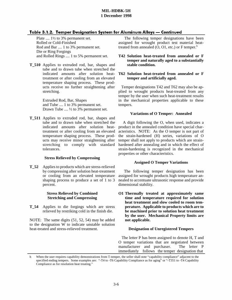
Plate .... 1½ to 3% permanent set.Rolled or Cold-FinishedRod and Bar .... 1 to 3% permanent set.Die or Ring Forgingsand Rolled Rings .... 1 to 5% permanent set.
T_510 Applies to extruded rod, bar, shapes andtube and to drawn tube when stretched theindicated amounts after solution heat-treatment or after cooling from an elevatedtemperature shaping process. These prod-ucts receive no further straightening afterstretching.
Extruded Rod, Bar, Shapesand Tube .... 1 to 3% permanent set.Drawn Tube .... ½ to 3% permanent set.
T_511 Applies to extruded rod, bar, shapes andtube and to drawn tube when stretched theindicated amounts after solution heat-treatment or after cooling from an elevatedtemperature shaping process. These prod-ucts may receive minor straightening afterstretching to comply with standardtolerances.
Stress Relieved by Compressing
T_52 Applies to products which are stress-relievedby compressing after solution heat-treatmentor cooling from an elevated temperatureshaping process to produce a set of 1 to 3percent.
Stress Relieved by CombinedStretching and Compressing
T_54 Applies to die forgings which are stressrelieved by restriking cold in the finish die.
NOTE: The same digits (51, 52, 54) may be addedto the designation W to indicate unstable solutionheat-treated and stress-relieved treatment.
The following temper designations have beenassigned for wrought product test material heat-treated from annealed (O, O1, etc.) or F temper.h
T42 Solution heat-treated from annealed or Ftemper and naturally aged to a substantiallystable condition.
T62 Solution heat-treated from annealed or Ftemper and artificially aged.
Temper designations T42 and T62 may also be ap-plied to wrought products heat-treated from anytemper by the user when such heat-treatment resultsin the mechanical properties applicable to thesetempers.
Variations of O Temper: Annealed
A digit following the O, when used, indicates aproduct in the annealed condition have special char-acteristics. NOTE: As the O temper is not part ofthe strain-hardened (H) series, variations of Otemper shall not apply to products which are strain-hardened after annealing and in which the effect ofstrain-hardening is recognized in the mechanicalproperties or other characteristics.
Assigned O Temper Variations
The following temper designation has beenassigned for wrought products high temperature an-nealed to accentuate ultrasonic response and providedimensional stability.
O1 Thermally treated at approximately sametime and temperature required for solutionheat treatment and slow cooled to room tem-perature. Applicable to products which are tobe machined prior to solution heat treatmentby the user. Mechanical Property limits arenot applicable.
Designation of Unregistered Tempers
The letter P has been assigned to denote H, T andO temper variations that are negotiated betweenmanufacturer and purchaser. The letter Pimmediately follows the temper designation that
h When the user requires capability demonstrations from T-temper, the seller shall note “capability compliance” adjacent to thespecified ending tempers. Some examples are: “-T4 to -T6 Capability Compliance as for aging” or “-T351 to -T4 CapabilityCompliance as for resolution heat treating.”

MIL-HDBK-5H1 December 1998
3-7
����� ���$� ���%�� ����������� &����� ��� �������� ������ ' ���������
most nearly pertains. Specific examples where suchdesignation may be applied include the following:
The use of the temper is sufficiently limited so as topreclude its registration. (Negotiated H tempervariations were formerly indicated by the third digitzero.)
The test conditions (sampling location, number ofsamples, test specimen configuration, etc.) aredifferent from those required for registration with theAluminum Association.
The mechanical property limits are not establishedon the same basis as required for registration with theAluminum Association.
It should be recognized not all combinations of stress and environment have been investigated, andit may be necessary to evaluate an alloy under the specific conditions involved for certain criticalapplications.
������� ���������� �� ������ —
��������� �������� ���� �� � ������� �� ������ �������� — The design strengthproperties at room temperature are listed at the beginning of the section covering the properties of an alloy.The effect of temperature on these properties is indicated in figures which follow the tables.
The A- and B-basis values for tensile properties for the direction associated with the specificationrequirements are based upon a statistical analysis of production quality control data obtained from spe-cimens tested in accordance with procurement specification requirements. For sheet and plate of heat-treatable alloys, the specified minimum values are for the long-transverse (LT) direction, while for sheetand plate of nonheat treatable alloys and for rolled, drawn, or extruded products, the specified minimumvalues are for the longitudinal (L) direction. For forgings, the specified minimum values are stated for atleast two directions. The design tensile properties in other directions and the compression, shear, andbearing properties are “derived” properties, based upon the relationships among the properties developedby tests of at least ten lots of material and applied to the appropriate established A, B, or S properties. Allof these properties are representative of the regions from which production quality control specimens aretaken, but may not be representative of the entire cross section of products appreciably thicker than the testspecimen or products of complex cross sections.
Tensile and compressive strengths are given for the longitudinal, long-transverse, and short-transverse directions wherever data are available. Short-transverse strengths may be relatively low, andtransverse properties should not be assumed to apply to the short-transverse direction unless so stated. Inthose instances where the direction in which the material will be used is not known, the lesser of theapplicable longitudinal or transverse properties should be used.
Bearing strengths are given without reference to direction and may be assumed to be about thesame in all directions, with the exception of plate, die forging, and hand forging. A reduction factor is usedfor edgewise bearing load in thick bare and clad plate of 2000 and 7000 series alloys. The results ofbearing tests on longitudinal and long-transverse specimens taken edgewise from plate, die forging, andhand forging have shown that the edgewise bearing strengths are substantially lower than those ofspecimens taken parallel to the surface. The bearing specimen orientations in thick plate are shown inFigure 3.1.2.1.1(a). For plate, bearing specimens are oriented so that the width of the specimen is parallelto the surfaces of the plate (flatwise); consequently, in cases where the stress condition approximates thatof the longitudinal or long-transverse edgewise orientations, the reductions in design values shown in Table3.1.2.1.1 should be made.

MIL-HDBK-5H1 December 1998
3-8
(����� ���$���� � ������ �%� ��������������� �� ��� ) %�����
����� ���$��� ������ *��%�������� ����� ��� ��� ) *���� �� $+++ ���,+++ &����� ������
Thickness (in.) ...
Bearing PropertyReduction, percent
1.001-6.000
Fbru (e/D = 1.5)Fbru (e/D = 2.0)Fbry (e/D = 1.5)Fbry (e.D = 2.0)
1510 5 5
It should be noted that in recent years, bearing data have been presented from tests made in accord-ance with ASTM E 238 which requires clean pins and specimens. See Reference 3.1.2.1.1 for additionalinformation. Designers should consider a reduction factor in applying these values to structural analyses.
For die and hand forgings, bearing specimens are taken edgewise so that no reduction factor isnecessary. In the case of die forgings, the location of bearing specimens is shown in Figures 3.1.2.1.1(b)and (c). For die forgings with cross-sectional shapes in the form of an I-beam or a channel, longitudinalbearing specimens are oriented so the width of the specimens is normal to the parting plane (edgewise).The specimens are positioned so the bearing test holes are midway between the parting plane and the top ofthe flange. The severity of metal flow at the parting plane near the flash can be expected to vary con-siderably for web-flange type die forgings; therefore, for consistency, the bearing test hole should not belocated on the parting plane. However, in the case of large, bulky-type die forgings, with a cross-sectionalshape similar to a square, rectangle, or trapezoid, as shown in Figure 3.1.2.1.1(c), longitudinal bearingspecimens are oriented edgewise to the parting plane, but the specimens are positioned so the bearing testholes are located on the parting plane. Similarly, for hand forgings, bearing specimens are orientededgewise and the specimens are positioned at the ½ thickness location.
Shear strengths also vary to some extent with plane of shear and direction of loading but the differ-ences are not so consistent [Reference 3.1.2.1.1(c)]. The standard test method for the determination ofshear strength of aluminum alloy products, 3/16 inch and greater in thickness, is contained in ASTM B769.
Shear strength values are presented without reference to grain direction, except for hand forgings.For products other than hand forgings, the lowest shear strength exhibited by tests in the various grain

MIL-HDBK-5H1 December 1998
3-9
(����� ���$���� � ������ �%� ��������������� ��� -��.������ ��%� �����������
(����� ���$��� � ������ �%� ��������������� ��� ��� ) ����.�� ���� �����������
directions is the design value. For hand forgings, the shear strength in short-transverse direction may be significantly lower than for the other two grain directions. Consequently, the shear strength for handforgings is presented for each grain direction.
For clad sheet and plate (i.e., containing thin surface layers of material of a different compositionfor added corrosion protection), the strength values are representative of the composite (i.e., the claddingand the core). For sheet and thin plate (�0.499 inch), the quality-control test specimens are of the fullthickness, so that the guaranteed tensile properties and the associated derived values for these productsdirectly represent the composite. For plate �0.500 inch in thickness, the quality-control test specimens aremachined from the core so the guaranteed tensile properties in specifications reflect the core material only,not the composite. Therefore, the design tensile properties for the thicker material are obtained byadjustment of the specification tensile properties and the other related properties to represent thecomposite, using the nominal total cladding thickness and the typical tensile properties of the claddingmaterial.
For clad aluminum sheet and plate products, it is also important to distinguish between primary andsecondary modulus values. The initial, or primary, modulus represents an average of the elastic moduli ofthe core and cladding; it applies only up to the proportional limit of the cladding. For example, the primarymodulus of 2024-T3 clad sheet applies only up to about 6 ksi. Similarly, the primary modulus of 7075-T6clad sheet applies only up to approximately 12 ksi. A typical use of primary moduli is for low amplitude,high frequency fatigue.
��������� �� ����� � — Elongation values are included in the tables of room-temperaturemechanical properties. In some cases where the elongation is a function of material thickness, asupplemental table is provided. Short-transverse elongations may be relatively low, and long-transversevalues should not be assumed to apply to the short-transverse direction.
��������� ������������� ������ ����� — The stress-strain relationships presented, which includeelastic and compressive tangent moduli, are typical curves based on three or more lots of test data. Beingtypical, these curves will not correspond to yield strength data presented as design allowables (minimumvalues). However, the stress-strain relationships are no less useful, since there are well-known methods forusing these curves in design by reducing them to a minimum curve affine to the typical curve or by usingRamberg-Osgood parameters obtained from the typical curves.
MIL-HDBK-5H1 December 1998
3-10
��������� ����� ��� ������ ������� — Sustained stressing at elevated temperature sufficientto result in appreciable amounts of creep deformation (e.g., more than 0.2 percent) may result in decreasedstrength and ductility. It may be necessary to evaluate an alloy under its stress-temperature environmentfor critical applications where sustained loading is anticipated (see Reference 3.1.2.1.4).
��������� ������� — Fatigue S/N curves are presented for those alloys for which sufficient dataare available. Data for both smooth and notched specimens are presented. The data from which the curveswere developed were insufficient to establish scatter bands and do not have the statistical reliability of theroom-temperature mechanical properties; the values should be considered to be representative for therespective alloys.
The fatigue strengths of aluminum alloys, with both notched and unnotched specimens, are at leastas high or higher at subzero temperatures than at room temperature [References 3.1.2.1.5(a) through (c)].At elevated temperatures, the fatigue strengths are somewhat lower than at room temperature, thedifference increasing with increase in temperature.
The data presented do not apply directly to the design of structures because they do not take intoaccount the effect of stress raisers such as reentrant corners, notches, holes, joints, rough surfaces, andother similar conditions which are present in fabricated parts. The localized high stresses induced infabricated parts by such stress raisers are of much greater importance for repeated loading than they are forstatic loading and may reduce the fatigue life of fabricated parts far below that which would be predictedby comparing the smooth-specimen fatigue strength directly with the nominal calculated stresses for theparts in question. See References 3.1.2.1.5 (d) through (q) for information on how to use high-strengthaluminum alloys, Reference 3.1.2.1.5(r) for details on the static and fatigue strengths of high-strengthaluminum-alloy bolted joints, Reference 3.1.2.1.5(s) for single-rivet fatigue-test data, and Reference1.4.9.3(b) for a general discussion of designing for fatigue. Fatigue-crack-growth data are presented in thevarious alloy sections.
��������� �������� ������� — Typical values of plane-strain fracture toughness, KIc, [Refer-ence 3.1.2.1.6(a)] for the high-strength aluminum alloy products are presented in Table 3.1.2.1.6. Mini-mum, average, and maximum values as well as coefficient of variation are presented for the alloys andtempers for which valid data are available [References 3.1.2.1.6(b) through (j)]. Although representative,these values do not have the statistical reliability of the room-temperature mechanical properties.
Graphic displays of the residual strength behavior of center-cracked tension panels are presented inthe various alloy sections. The points denote the experimental data from which the curve of fracturetoughness was derived.
�������� ��� ����� ����������� — In general, the strengths (including fatigue strengths) ofaluminum alloys increase with decrease in temperature below room temperature [References 3.1.2.1.7(a)and (b)]. The increase is greatest over the range from about -100 to -423�F (liquid hydrogen temperature);the strengths at -452�F (liquid helium temperature) are nearly the same as at -423�F [References3.1.2.1.7(c) and (d)]. For most alloys, elongation and various indices of toughness remain nearly constantor increase with decrease in temperature, while for the 7000 series, modest reductions are observed [Refer-ences 3.1.2.1.7(d) and (e)]. None of the alloys exhibit a marked transition in fracture resistance over a nar-row range of temperature indicative of embrittlement.

MIL-H
DB
K-5H
1 Decem
ber 1998
3-1
1
����� ������� ��� �� �� ������������� �� ������������ ����� �� �� ������ �� �� ��� � ���� ��
Alloy/TemperProductForm
Orien-tationb
ProductThickness
Range,inches
Numberof
SourcesSample
Size
SpecimenThickness
Range,inches
KIC, ksi ��in.
Max. Avg. Min.Coefficient of
VariationMinimum
SpecificationValue
2014-T6512014-T6512014-T6522014-T6522024-T3512024-T8512024-T8512024-T8512024-T8522024-T8522024-T8522124-T8512124-T8512124-T8512219-T8512219-T8512219-T8512219-T8512219-T85112219-T8522219-T8522219-T8522219-T872219-T877049-T737049-T737049-T737049-T737049-T737050-T73517050-T73517050-T73517050-T74
PlatePlateHand ForgingHand ForgingPlatePlatePlatePlateForgingHand ForgingHand ForgingPlatePlatePlatePlatePlatePlateForgingExtrusionForgingHand ForgingHand ForgingPlatePlateDie ForgingDie ForgingHand ForgingHand ForgingHand ForgingPlatePlatePlateDie Forging
L-TT-LL-TT-LL-TL-SL-TT-LT-LL-TT-LL-TT-LS-LL-TT-LS-LS-LT-LS-LL-TT-LL-TT-LL-TS-LL-TT-LS-LL-TT-LS-LS-L
�0.5�0.5�0.5�0.8�1.0
1.4-3.0�0.5
0.4-4.02.0-7.0
--------�0.8
0.6-6.0�0.5----�1.0�0.8----------------�1.5�1.5----1.4�0.5�0.5
2.0-7.11.0
1.0-6.02.0-6.02.0-6.00.6-7.1
122224119342131064631122231332222113
24341515111110280203517497509489671082485196032281111214628272431293012
0.5-1.00.5-1.00.8-2.00.8-2.00.8-2.00.5-0.80.4-1.40.4-1.40.7-2.00.8-2.00.7-2.00.5-2.50.5-2.00.3-1.51.0-2.50.8-2.50.5-1.51.0-1.51.8-2.00.8-2.01.5-2.51.5-2.50.8-2.0
1.00.5-1.00.5-1.00.5-1.0
1.00.8-1.01.0-2.01.5-2.00.8-1.50.6-2.0
252348304332322525382238322738372634343546303422342637282243353027
222131213125232019281829252133292225292538272722302230221935302824
191824182720151815191418191630202019232030222519271823181428252521
8.46.521.814.416.517.810.18.815.518.414.410.49.79.87.210.19.612.112.312.19.78.49.33.97.49.712.112.514.211.38.54.68.8
242018
a These values are for information only. b Refer to Figure 1.4.12.3 for definition of symbols. c Varies with thickness.

MIL-H
DB
K-5H
1 Decem
ber 1998
3-1
2
����� ������� ��� �� �� ������������� �� ������������ ����� �� �� ������ �� �� ��� ����� ��!"����� �#
Alloy/TemperProductForm
Orien-tationb
ProductThickness
Range,inches
Numberof
SourcesSample
Size
SpecimenThickness
Range,inches
KIC, ksi��in.
Max. Avg. Min.Coefficientof Variation
MinimumSpecification
Value
7050-T74517050-T74517050-T74517050-T74527050-T74527050-T74527050-T765117075-T6517075-T6517075-T6517075-T65107075-T65107075-T65107075-T65107075-T737075-T737075-T737075-T73517075-T73517075-T73517075-T735117075-T735117075-T735117075-T735117075-T73527075-T73527075-T76517075-T76517075-T76517075-T76517075-T76517075-T765117075-T76511
PlatePlatePlateHand ForgingHand ForgingHand ForgingExtrusionPlatePlatePlateExtrusionExtrusionForged BarForged BarDie ForgingHand ForgingHand ForgingPlatePlatePlateExtrusionExtrusionExtrusionExtrusionHand ForgingHand ForgingPlatePlatePlateClad PlateClad PlateExtrusionExtrusion
L-TT-LS-LL-TT-LS-LL-TL-TT-LS-LL-TT-LL-TT-LT-LL-TT-LL-TT-LS-LT-LL-TT-LS-LL-TT-LL-TT-LS-LL-TT-LL-TT-L
----�1.0�1.0
3.5-5.53.5-7.53.5-7.5
----�0.6�0.5----
0.7-3.50.7-3.50.7-5.00.7-5.0�0.5----�1.0�1.0�0.5�0.5
1.0-7.0�0.9�0.7�0.5----�0.8�0.8�0.5�0.5
0.5-0.60.5-0.61.3-7.0
1.2
1396111275211111228631333236752243
9697441113173899135372625131322101465562019283515272082962830561142
1.0-2.00.5-2.00.7-2.0
1.51.5
0.8-1.50.6-2.00.5-2.00.4-2.00.5-1.50.5-1.20.5-1.20.6-2.00.5-2.50.5-0.81.0-1.51.0-1.50.5-2.00.5-2.00.5-1.50.9-1.00.7-2.00.5-1.80.4-1.00.8-2.00.8-2.00.5-2.00.5-2.00.4-0.80.5-0.60.5-0.61.2-2.00.6-2.0
393828342221403027223228352425392736473822433522393343282030284136
322823312119312622182724292121312330272220352320332629231825243523
252121261816272018142321241718292025211719311217302322201522213120
11.715.66.38.06.77.57.87.68.910.47.88.011.68.29.98.89.08.220.132.53.79.420.39.09.29.917.87.67.77.17.711.015.5
c
c
c
c
c
c
a These values are for information only. b Refer to Figure 1.4.12.3 for definition of symbols. c Varies with thickness.

MIL-H
DB
K-5H
1 Decem
ber 1998
3-1
3
����� ������� ��� �� �� ������������� �� ������������ ����� �� �� ������ �� �� ��� ����� ��!"����� �#
Alloy/TemperProductForm
Orien-tationb
ProductThickness
Range,inches
Numberof
SourcesSample
Size
SpecimenThickness
Range,inches
KIC, ksi��in.
Max. Avg. Min.Coefficientof Variation
MinimumSpecification
Value
7175-T6/T65117175-T6517175-T6517175-T65117175-T73517175-T73517175-T735117175-T735117175-T747175-T747175-T747175-T747175-T76517175-T76517175-T76517175-T76517175-T765117175-T765117475-T6517475-T6517475-T6517475-T73517475-T73517475-T73517475-T76517475-T7651
ExtrusionPlatePlateExtrusionPlatePlateExtrusionExtrusionDie ForgingDie ForgingDie ForgingHand ForgingClad PlateClad PlatePlatePlateExtrusionExtrusionPlatePlatePlatePlatePlatePlatePlatePlate
T-LL-TT-LL-TL-TT-LL-TT-LL-TT-LS-LT-LL-TT-LL-TT-LL-TT-LL-TT-LS-LL-TT-LS-LL-TT-L
------------------------�0.7�0.5�0.5�0.5�0.5
3.0-5.0----------------
1.4-3.8�0.6----
0.6-2.0�0.6
1.3-4.0�1.3�0.7
1.0-2.0�1.0
21122255324211112432187742
2517101430324343141341105350121148493414323151132741015
0.8-1.00.7-0.80.7-0.80.8-1.00.7-1.60.7-1.60.5-1.50.5-1.50.5-1.00.5-1.00.5-0.81.0-1.5
1.50.61.51.5
0.6-2.00.6-1.80.9-2.00.6-2.00.5-1.01.3-3.00.7-3.00.5-1.51.0-2.00.9-2.0
2430263636304735383331293328322639314943366050364650
2126223233273325302426263227322533223834284737304136
1824202432252320222120243025312427203327203429253629
7.99.29.813.83.34.516.010.915.015.78.64.84.33.11.73.310.79.89.29.814.910.410.48.76.214.5
302227212125
3028
cc
253330
a These values are for information only. b Refer to Figure 1.4.12.3 for definition of symbols. c Varies with thickness.

MIL-HDBK-5H1 December 1998
3-14
The tensile and shear moduli of aluminum alloys also increase with decreasing temperature so thatat -100, -320, and -423�F, they are approximately 5, 12, and 16 percent, respectively, above the roomtemperature values [Reference 3.1.2.1.7(f)].
�������� �������� ����������� — In general, the strengths of aluminum alloys decrease andtoughness increases with increase in temperature and with time at temperature above room temperature; theeffect is generally greatest over the temperature range from 212 to 400�F. Exceptions to the general trendsare tempers developed by solution heat treatment without subsequent aging, for which the initial elevatedtemperature exposure results in some age hardening and reduction in toughness; further time at temperaturebeyond that required to achieve peak hardness results in the aforementioned decrease in strength andincrease in toughness [Reference 3.1.2.1.8].
������� �������� �� ������� — Where available from the literature, the average values of certainphysical properties are included in the room-temperature tables for each alloy. These properties includedensity, �, in lb/in.3; the specific heat, C, in Btu/(lb)(�F); the thermal conductivity, K, inBtu/[(hr)(ft2)(�F)/ft]; and the mean coefficient of thermal expansion, �, in in./in./�F. Where more extensivedata are available to show the effect of temperature on these physical properties, graphs of physicalproperty as a function of temperature are presented for the applicable alloys.
������� ��������� ���������� —
��������� ���������� � �������� �� �� � ���� ��� !��� ��"������� #$%$&$#$%�� ��� �����' — The high-strength heat treatable wrought aluminum alloys in certain tempers are susceptible tostress-corrosion cracking, depending upon product, section size, direction and magnitude of stress. Thesealloys include 2014, 2025, 2618, 7075, 7150, 7175, and 7475 in the T6-type tempers and 2014, 2024, 2124,and 2219 in the T3 and T4-type tempers. Other alloy-temper combinations, notably 2024, 2124, 2219, and2519 in the T6- or T8-type tempers and 7010, 7049, 7050, 7075, 7149, 7175, and 7475 in the T73-type tem-pers, are decidedly more resistant and sustained tensile stresses of 50 to 75 percent of the minimum yieldstrength may be permitted without concern about stress corrosion cracking. The T74 and T76 tempers of7010, 7075, 7475, 7049, 7149, and 7050 provide an intermediate degree of resistance to stress-corrosioncracking, i.e., superior to that of the T6 temper, but not as good as that of the T73 temper of 7075. Toassist in the selection of materials, letter ratings indicating the relative resistance to stress-corrosion crack-ing of various mill product forms of the wrought 2000, 6000, and 7000 series heat-treated aluminum alloysare presented in Table 3.1.2.3.1(a). This table is based upon ASTM G 64 which contains more detailedinformation regarding this rating system and the procedure for determining the ratings. In addition, morequantitative information in the form of the maximum specified tension stresses at which test specimens willnot fail when subjected to the alternate immersion stress-corrosion test described in ASTM G 47 are shownin Tables 3.1.2.3.1(b) through (e) for various heat-treated aluminum product forms, alloys, and tempers.
Where short times at elevated temperatures of 150 to 500�F may be encountered, the precipitationheat-treated tempers of 2024 and 2219 alloys are recommended over the naturally aged tempers.
Alloys 5083, 5086, and 5456 should not be used under high constant applied stress for continuousservice at temperatures exceeding 150�F, because of the hazard of developing susceptibility to stress-corrosion cracking. In general, the H34 through H38 tempers of 5086, and the H32 through H38 tempersof 5083 and 5456 are not recommended, because these tempers can become susceptible to stress-corrosioncracking.
For the cold forming of 5083 sheet and plate in the H112, H321, H323, and H343 tempers and5456 sheet and plate in the H112 and H321 tempers, a minimum bend radius of 5T should be used. Hotforming of the O temper for alloys 5083 and 5456 is recommended, and is preferred to the cold worked

MIL-HDBK-5H1 December 1998
3-15
����� ���$����� � �������� � �� &�����.��������� �������� ��� /���.&��������������� ����� *���� ��
Alloy andTemperb
TestDirectionc
RolledPlate
Rod andBard
ExtrudedShapes Forging
2014-T6
2024-T3, T4
2024-T6
2024-T8
2124-T8
2219-T351X, T37
2219-T6
2219-T85XX, T87
6061-T6
7049-T73
7049-T76
7050-T74
7050-T76
7075-T6
7075-T73
LLTSTL
LTSTL
LTSTL
LTSTL
LTSTL
LTSTL
LTSTL
LTSTL
LTSTL
LTSTL
LTSTL
LTSTL
LTSTL
LTSTL
LTST
ABe
DABe
Df
f
f
AABAABABDAAAAAAAAAAAAf
f
f
AABAACABe
DAAA
ADDADDABBAAAf
f
f
f
f
f
AAAf
f
f
AAAf
f
f
f
f
f
f
f
f
ABBADDAAA
ABe
DABe
Df
f
f
AABf
f
f
ABDAAAAAAAAAAABAACAABAACABe
DAAA
BBe
Df
f
f
AAe
DAACf
f
f
f
f
f
AAAAAAAAAAAAf
f
f
AABf
f
f
ABe
DAAA

MIL-HDBK-5H1 December 1998
3-16
����� ���$����� � �������� � �� &�����.��������� �������� ��� /���.&��������������� ����� *���� ��'���������
Alloy andTemperb
TestDirectionc
RolledPlate
Rod andBard
ExtrudedShapes Forging
7075-T74
7075-T76
7149-T73
7175-T74
7475-T6
7475-T73
7475-T76
LLTSTL
LTSTL
LTSTL
LTSTL
LTSTL
LTSTL
LTST
f
f
f
AACf
f
f
f
f
f
ABe
DAAAAAC
f
f
f
f
f
f
f
f
f
f
f
f
f
f
f
f
f
f
f
f
f
f
f
f
AACAABf
f
f
f
f
f
f
f
f
f
f
f
AABf
f
f
AAAAABf
f
f
f
f
f
f
f
f
a Ratings were determined from stress corrosion tests performed on at least ten random lots for which test results showed 95%
conformance at the 95% confidence level when tested at the stresses indicated below. A practical interpretation of these ratings
follows the rating definition.
A - Equal or greater than 75% of the specified minimum yield strength. Very high. No record of service problems and SCC not
anticipated in general applications.
B - Equal or greater than 50% of the specified minimum yield strength. High. No record of service problems and SCC not
anticipated at stresses of the magnitude caused by solution heat treatment. Precautions must be taken to avoid high sustained
tensile stress exceeding 50% of the minimum specified yield strength produced by any combination of sources including heat
treatment, straightening, forming, fit-up, and sustained service loads.
C - Equal or greater than 25% of the specified minimum yield strength. Intermediate. SCC not anticipated if the total sustained
tensile strength is less than 25% of the minimum specified yield strength. This rating is designated for the short transverse
direction in improved products used primarily for high resistance to exfoliation corrosion in relatively thin structures where
applicable short transverse stresses are unlikely.
D - Fails to meet the criterion for the rating C. Low. SCC failures have occurred in service or would be anticipated if there is any
sustained tensile stress in the designated test direction. This rating currently is designated only for the short transverse direction
in certain materials.
NOTE - The above stress levels are not to be interpreted as "threshold" stresses, and are not recommended for design. Other
documents, such as MIL-STD-1568, NAS SD-24, and MSFC-SPEC-522A, should be consulted for design
recommendations.

MIL-HDBK-5H1 December 1998
3-17
����� ���$����� � �������� � �� &�����.��������� �������� ��� /��� &��������������� ����� *���� ��'���������
b The ratings apply to standard mill products in the types of tempers indicated, including stress-relieved tempers, and could be
invalidated in some cases by application of nonstandard thermal treatments of mechanical deformation at room temperature by the
user.
c Test direction refers to orientation of the stressing direction relative to the directional grain structure typical of wrought materials,
which in the case of extrusions and forgings may not be predictable from the geometrical cross section of the product.
L�Longitudinal: parallel to the direction of principal metal extension during manufacture of the product.
LT�Long Transverse: perpendicular to direction of principal metal extension. In products whose grain structure clearly shows
directionality (width to thickness ratio greater than two) it is that perpendicular direction parallel to the major grain dimension.
ST�Short Transverse: perpendicular to direction of principal metal extension and parallel to minor dimension of grains in
products with significant grain directionality.
d Sections with width-to-thickness ratio equal to or less than two for which there is no distinction between LT and ST.
e Rating is one class lower for thicker sections: extrusion, 1 inch and over; plate and forgings, 1.5 inches and over.
f Ratings not established because the product is not offered commercially.
NOTE: This table is based upon ASTM G 64.

MIL-HDBK-5H1 December 1998
3-18
����� ���$����� � 0�#���� &%� ����� ������� &����� �� ��� � ���� &%� ����� ���� 1��(��� �� �23 1��� ��������� "�������� ����� ��� 4������ &����� ��������� ����������������� ����� *����
Alloy and TemperTest
DirectionThickness,
inchesStress,
ksi Referenced Specifications
2024-T851
2090-T81c
2124-T851
2124-T8151c
2219-T851
2219-T87
2519-T877010-T7351c
7010-T7451
7010-T76517049-T73517050-T74517050-T76517075-T7351
7075-T7651Clad 7075-T76517150-T77517475-T73517475-T7651
ST
STST
ST
ST
ST
STST
ST
STSTSTSTST
STSTSTSTST
1.001-4.0004.001-6.0000.750-1.5001.500-1.9992.000-4.0004.001-6.0001.500-3.0003.001-5.0005.001-6.0000.750-2.0002.001-4.0004.001-5.0005.001-6.0000.750-3.0003.001-4.0004.001-5.0000.750-4.0000.750-3.0003.001-5.0005.001-5.5000.750-3.0003.001-5.5000.750-5.5000.750-5.0000.750-6.0000.750-3.0000.750-2.0002.001-2.5002.501-4.0000.750-1.0000.750-1.0000.750-3.0000.750-4.0000.750-1.500
28a
27a
20
28a
28a
27a
30a
29a
28a
34b
33b
32b
31b
38b
37b
36b
43b
41b
40b
39b
31a
35
25
45
35
25
42b
39b
36b
25
25
25
40
25
Company specification
AMS 4303AMS 4101AMS-QQ-A-0025/29, ASTM B 209, AMS 4101
AMS 4221
AMS-QQ-A-250/30
AMS-QQ-A-250/30
MIL-A-46192AMS 4203
AMS 4205
AMS 4204AMS 4200AMS 4050AMS 4201AMS-QQ-A-250/12, AMS 4078, ASTM B 209
AMS-QQ-A-00250/24, ASTM B 209AMS-QQ-A-00250/25, ASTM B 209AMS 4252AMS 4202AMS 4089
a 50% of specified minimum long transverse yield strength.
b 75% of specified minimum long transverse yield strength.
c Design values are not included in MIL-HDBK-5.
d Most specifications reference ASTM G 47, which requires exposures of 10 days for 2XXX alloys and 20 days for 7XXX alloys in
ST test direction.
DO NOT USE STRESS VALUES FOR DESIGN

MIL-H
DB
K-5H
1 Decem
ber 1998
3-1
9
����� ������$�%� &�'�� � ��������# ������� ������ �� (���� ���� ��������� (��� )�� ���� �� �*+ )�"� ���������,�������� ����� ��� ����� � ������ "�������� ��������� �� ��� � ���� �����# -���. ��#�. ��# /'�� �����
Alloy and Temper Product FormTest
DirectionThickness,
inchesStress,
ksi Referenced Specifications
7075-T73-T7351
2219-T85117049-T73511
7049-T76511d
7050-T735117050-T745117050-T765117075-T73-T73510-T73511
7075-T76-T76510-T765117149-T73511d
7150-T775117175-T73511
Rolled Bar and RodExtrusionExtrusion
ExtrusionExtrusionExtrusionExtrusionExtrusion
ExtrusionExtrusion
ExtrusionExtrusion
ST
STST
STSTSTSTST
STST
STST
0.750-3.000
0.750-3.0000.750-2.9993.000-5.0000.750-5.0000.750-5.0000.750-5.0000.750-5.0000.750-1.4991.500-2.9993.000-4.9993.000-4.9990.750-1.0000.750-2.9993.000-5.0000.750-2.0000.750-2.000
42a
30
41b
40b
20
45
35
17
45a
44a
42a
41a,c
25
41b
40b
25
44
AMS-QQ-A-225/9, AMS 4124, ASTM B211
AMS 4162, AMS 4163AMS 4157
AMS 4159AMS 4341AMS 4342AMS 4340AMS-QQ-A-200/11, AMS 4166, AMS 4167, ASTM B 211
AMS-QQ-A-200/15, ASTM B 221AMS 4543
AMS 4345AMS 4344
a 75% of specified minimum longitudinal yield strength.b 65% of specified minimum longitudinal yield strength.c Over 20 square inches cross-sectional area.d Design values are not included in MIL-HDBK-5.e Most specifications reference ASTM G 47, which requires exposures of 10 days for 2XXX alloys and 20 days for 7XXX alloys in ST test direction.
DO NOT USE STRESS VALUES FOR DESIGN

MIL-HDBK-5H1 December 1998
3-20
����� ���$����� � 0�#���� &%� ����� ������� &����� �� ��� � ���� &%� ����� ����1�� (��� �� �23 1��� ��������� "�������� ����� ��� 4������ &����� ��������� ����������������� ��� (�������
Alloy and TemperTest
DirectionThickness,
inchesStress,
ksi Referenced Specifications
7049-T73
7050-T747050-T74527075-T73
7075-T7352
7075-T7354c
7075-T74c
7149-T73
7175-T74
7175-T7452c
ST
STSTST
ST
STST
ST
ST
ST
0.750-2.0002.001-5.0000.750-6.0000.750-4.0000.750-3.0003.001-4.0004.001-5.0005.001-6.0000.750-4.000
3.001-4.0000.750-3.0000.750-3.0003.001-4.0004.001-5.0005.001-6.0000.750-2.0002.001-5.0000.750-3.0003.001-4.0004.001-5.0005.001-6.0000.750-3.000
46a
45a
35
35
42a
41a
39a
38a
42a
39a
42
35
31b
30b
29b
46a
45a
35
31b
30b
29b
35
QQ-A-367, AMS 4111, ASTM B 247
AMS 4107AMS 4333MIL-A-22771, QQ-A-367AMS 4241, ASTM B 247AMS 4141
MIL-A-22771, QQ-A-367, AMS 4147,ASTM B 247
Company SpecificationAMS 4131
AMS 4320
AMS 4149, ASTM B 247AMS 4149
AMS 4179
a 75% of specified minimum longitudinal yield strength.
b 50% of specified minimum longitudinal yield strength.c Design values are not included in MIL-HDBK-5.
d Most specifications Reference ASTM G 47, which requires 20 days of exposure for 7XXX alloys in ST test direction.
DO NOT USE STRESS VALUES FOR DESIGN

MIL-HDBK-5H1 December 1998
3-21
����� ���$����� � 0�#���� &%� ����� ������� &����� �� ��� � ���� &%� ����� ����1�� (��� �� �23 1��� ��������� "�������� ����� ��� 4������ &����� ��������� ����������������� /��� (�������
Alloy and TemperTest
DirectionThickness,
inchesStress,
ksi Referenced Specifications
7049-T73
7049-T7352e
7050-T74527075-T73
7075-T7352
7075-T74e
7075-T7452e
7149-T73
7175-T74
7175-T7452
ST
ST
STST
ST
ST
ST
ST
ST
ST
2.001-3.0003.001-4.0004.001-5.0000.750-3.0003.001-4.0004.001-5.0000.750-8.0000.750-3.0003.001-4.0004.001-4.0005.001-6.0000.750-3.0003.001-4.0004.001-5.0005.001-6.0000.750-3.0003.001-4.0004.001-5.0005.001-6.0000.750-2.0002.001-3.0003.001-4.0004.001-5.0005.001-6.0002.000-3.0003.001-4.0004.001-5.0000.750-3.0003.001-4.0004.001-5.0004.001-6.0000.750-3.0003.001-4.0004.001-5.0005.001-6.000
45a
44a
42a
44a
43a
40a
35
42a
41a
39a
38a
39c
37c
36c
34c
35
30b
28b
27b
35
29d
28d
26d
24d
44c
43c
42c
35
29d
28d
26d
35
27d
26d
24d
QQ-A-367, AMS 4111, ASTM B 247
AMS 4247
AMS 4108MIL-A-22771, QQ-A-367, ASTM B 247
AMS 4147
AMS 4131
AMS 4323
AMS 4320
AMS 4149
AMS 4179
a 75% of specified minimum longitudinal yield strength.
b 50% of specified minimum longitudinal yield strength.c 75% of specified minimum long transverse yield strength.
d 50% of specified minimum long transverse yield strength.e Design values are not included in MIL-HDBK-5.
f Most specifications Reference ASTM G 47, which requires 20 days of exposure for 7XXX alloys in ST test direction.
DO NOT USE STRESS VALUES FOR DESIGN

MIL-HDBK-5H1 December 1998
3-22
tempers to avoid excessive cold work and high residual stress. If the cold worked tempers are heat-treatable alloys are heated for hot forming, a slight decrease in mechanical properties, particularly yieldstrength, may result.
��������� ���������� � �(" ����� � !��"������ #$%$&$#$&' � The high-strength wroughtaluminum alloys in certain tempers are susceptible to exfoliation corrosion, dependent upon product andsection size. Generally those alloys and tempers that have the lowest resistance to stress-corrosion crack-ing also have the lowest resistance to exfoliation. The tempers that provide improved resistance to stress-corrosion cracking also provide improved resistance or immunity to exfoliation. For example, the T76temper of 7075, 7049, 7050, and 7475 provides a very high resistance to exfoliation, i.e., decidedlysuperior to the T6 temper, and almost the immunity provided by the T73 temper of 7075 alloy (seeReference 3.1.2.3.2).
����� ������� ����� ������ ����
������� �������� ���������������� �������� — In order to avoid stress-corrosioncracking (see Section 3.1.2.3), practices, such as the use of press or shrink fits; taper pins; clevis joints inwhich tightening of the bolt imposes a bending load on female lugs; and straightening or assembly opera-tions; which result in sustained surface tensile stresses (especially when acting in the short-transverse grainorientation), should be avoided in these high-strength alloys: 2014-T451, T4, T6, T651, T652; 2024-T3,T351, T4; 7075-T6, T651, T652; 7150-T6151, T61511; and 7475-T6, T651.
Where straightening or forming is necessary, it should be performed when the material is in thefreshly quenched condition or at an elevated temperature to minimize the residual stress induced. Whereelevated temperature forming is performed on 2014-T4 T451, or 2024-T3 T351, a subsequent precipitationheat treatment to produce the T6 or T651, T81 or T851 temper is recommended.
It is good engineering practice to control sustained short-transverse tensile stress at the surface ofstructural parts at the lowest practicable level. Thus, careful attention should be given in all stages ofmanufacturing, starting with design of the part configuration, to choose practices in the heat treatment,fabrication, and assembly to avoid unfavorable combinations of end grain microstructure and sustainedtensile stress. The greatest danger arises when residual, assembly, and service stress combine to producehigh sustained tensile stress at the metal surface. Sources of residual and assembly stress have been themost contributory to stress-corrosion-cracking problems because their presence and magnitude were notrecognized. In most cases, the design stresses (developed by functional loads) are not continuous andwould not be involved in the summation of sustained tensile stress. It is imperative that, for materials withlow resistance to stress-corrosion cracking in the short-transverse grain orientation, every effort be taken tokeep the level of sustained tensile stress close to zero.
������� ����������� �������������� �������� ������ — Cold working such asstretch forming of aluminum alloy prior to solution heat treatment may result in recrystallization or graingrowth during heat treatment. The resulting strength, particularly yield strength, may be significantlybelow the specified minimum values. For critical applications, the strength should be determined on thepart after forming and heat treating including straightening operations. To minimize recrystallizationduring heat treatment, it is recommended that forming be done after solution heat treatment in the as-quenched condition whenever possible, but this may result in compressive yield strength in the direction ofstretching being lower than MIL-HDBK-5 design allowables for user heat treat tempers.
������� ���������� ������� — The dimensional changes that occur in aluminum alloyduring thermal treatment generally are negligible, but in a few instances these changes may have to be con-sidered in manufacturing. Because of many variables involved, there are no tabulated values for thesedimensional changes. In the artificial aging of alloy 2219 from the T42, T351, and T37 tempers to the T62,T851, and T87 tempers, respectively, a net dimensional growth of 0.00010 to 0.0015 in./in. may be

MIL-HDBK-5H1 December 1998
3-23
anticipated. Additional growth of as much as 0.0010 in./in. may occur during subsequent service of a yearor more at 300�F or equivalent shorter exposures at higher temperatures. The dimensional changes thatoccur during the artificial aging of other wrought heat-treatable alloys are less than one-half that for alloy2219 under the same conditions.
������� !������ — The ease with which aluminum alloys may be welded is dependent princi-pally upon composition, but the ease is also influenced by the temper of the alloy, the welding process, andthe filler metal used. Also, the weldability of wrought and cast alloys is generally considered separately.
Several weldability rating systems are established and may be found in publications by the Alu-minum Association, American Welding Society, and the American Society for Metals. Handbooks fromthese groups can be consulted for more detailed information. Specification AA-R-566 also contains usefulinformation. This document follows most of these references in adopting a four level rating system. An“A” level, or readily weldable, means that the alloy (and temper) is routinely welded by the indicated pro-cess using commercial procedures. A “B” level means that welding is accomplished for many applications,but special techniques are required, and the application may require preliminary trials to developprocedures and tests to demonstrate weld performance. A “C” level refers to limited weldability becausecrack sensitivity, loss of corrosion resistance, and/or loss of mechanical properties may occur. A “D” levelindicates that the alloy is not commercially weldable.
The weldability of aluminum alloys is rated by alloy, temper, and welding process (arc or resis-tance). Tables 3.1.3.4(a) and (b) list the ratings in the alloy section number order in which they appear inChapter 3.
When heat-treated or work-hardened materials of most systems are welded, a loss of mechanicalproperties generally occurs. The extent of the loss (if not reheat treated) over the table strength allowableswill have to be established for each specific situation.

MIL-HDBK-5H1 December 1998
3-24
����� �����5�� � (���� ����� ����������� �� ������� �������� ������
MIL-HDBK-5Section No. Alloy Tempers
Weldabilitya,c
Inert Gas Metalor Tungsten Arc
ResistanceSpotb
3.2.1
3.2.23.2.3
3.2.43.2.53.2.63.2.7
3.2.83.2.93.5.1
3.5.2
3.5.3
3.5.4
3.5.5
3.6.13.6.2
3.6.33.7.13.7.2
3.7.33.7.43.7.53.7.63.7.7
2014
20172024
2025209021242219
261825195052
5083
5086
5454
5456
60136061
615170107049714970507075715071757475
OT6, T62, T651, T652, T6510, T6511
T4, T42, T451O
T3, T351, T361, T4, T42T6, T62, T81, T851, T861
T8510, T8511, T3510, T3511T6T83T851
OT62, T81, T851, T87, T8510, T8511
T61T87O
H32, H34, H36, H38O
H321, H323, H343, H111, H112O
H32, H34, H36, H38, H111, H112O
H32, H34, H111, H112O
H111, H321, H112T6O
T4, T42, T451, T4510, T4511, T6T62, T651, T652, T6510, T6511
T6AllAll
AllAllAllAllAll
CBCDCCCCBCAACAAAAAAAAAAAAAAAACC
CCCCC
DBBDBBBBBB
B-DAB...BABABABABAABAAABB
BBBBB
a Ratings A through D are relative ratings defined as follows:A - Generally weldable by all commercial procedures and methods.
B - Weldable with special techniques or for specific applications which justify preliminary trials or testing to develop welding procedures and weld performance.
C - Limited weldability because of crack sensitivity or loss in resistance to corrosion and mechanical properties.D - No commonly used welding methods have been developed.
b See MIL-W-6858 for permissible combinations.c When using filler wire, the wire should contain less than 0.0008 percent beryllium to avoid toxic fumes.

MIL-HDBK-5H1 December 1998
3-25
����� �����5�� � (���� ����� ������������ �� ���� �������� ������
MIL-HDBK-5Section No. Alloy
Weldabilityb,c
Inert Gas Metal orTungsten Arc Resistance Spot
3.8.13.9.13.9.23.9.33.9.43.9.53.9.63.9.73.9.8
A201.0354.0355.0
C355.0356.0
A356.0A357.0D357.0359.0
CBBBAAAAA
CBBBAABAB
a Weldability related to joining a casting to another part of same composition. The weldability ratings are not
applicable to minor weld repairs. Such repairs shall be governed by the contractors procedure for in-process weldingof castings, after approval by the procuring agency.
b Ratings A through D are relative ratings defined as follows:A - Generally weldable by all commercial procedures and methods.
B - Weldable with special techniques or for specific applications which justify preliminary trials or testingto develop welding procedure and weld performance.
C - Limited weldability because of crack sensitivity or loss in resistance to corrosion and mechanicalproperties.
D - No commonly used welding methods have been developed.c When using filler wire, the wire should contain less than 0.0008 percent beryllium to avoid toxic fumes.