chapter 3 - architecture configuration - · pdf filechapter 25 draas 2.0 inmage and ......
TRANSCRIPT
Implementation Guide Addedum
C H A P T E R 3
Architecture ConfigurationThis chapter includes the following major topics:
• VMDC VSA 1.0 System Architecture, page 3-26
• Cisco UCS, page 3-28
• VMware Virtual SAN, page 3-32
• DRaaS Application Suite, page 3-38
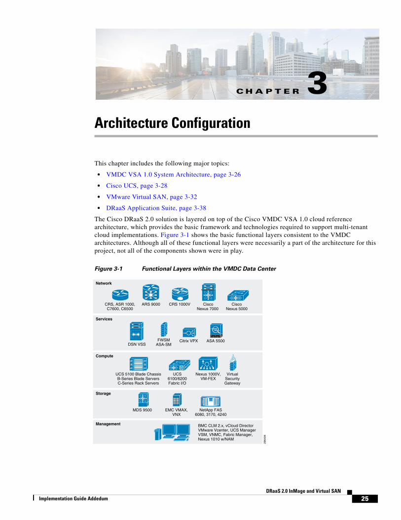
The Cisco DRaaS 2.0 solution is layered on top of the Cisco VMDC VSA 1.0 cloud reference architecture, which provides the basic framework and technologies required to support multi-tenant cloud implementations. Figure 3-1 shows the basic functional layers consistent to the VMDC architectures. Although all of these functional layers were necessarily a part of the architecture for this project, not all of the components shown were in play.
Figure 3-1 Functional Layers within the VMDC Data Center
Services
Network
Management
Storage
CiscoNexus 7000
CRS, ASR 1000,C7600, C6500
CRS 1000VARS 9000 CiscoNexus 5000
DSN VSSFWSM
ASA-SMCitrix VPX ASA 5500
Compute
2964
94
EMC VMAX,VNX
MDS 9500 NetApp FAS6080, 3170, 4240
UCS 5100 Blade ChassisB-Series Blade ServersC-Series Rack Servers
BMC CLM 2.x, vCloud DirectorVMware Vcenter, UCS ManagerVSM, VNMC, Fabric Manager,Nexus 1010 w/NAM
UCS6100/6200Fabric I/O
Nexus 1000V,VM-FEX
VirtualSecurityGateway
25DRaaS 2.0 InMage and Virtual SAN

Chapter 3 Architecture Configuration
The basic tenancy model is illustrated in Figure 3-2. It consists of a network fabric (Layer 2 & 3 switching), Layer 4-7 services (e.g., firewall and load balancing), and compute. From this infrastructure, multiple virtualized contexts—tenants—are logically created.
Figure 3-2 Multi-tenancy Design
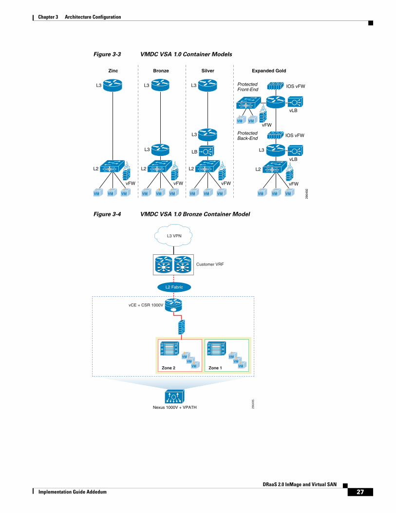
VMDC VSA 1.0 System ArchitectureVarious tenant container models that are available, validated, and supported in the VSA 1.0 architecture are differentiated by the services they provide to the individual tenants. Figure 3-3 provides an overview of these tenant container models. For this project, the Bronze Container model was used at the SP site to provide tenancy to the Enterprise customer. Figure 3-4 illustrates the details of the Bronze Container model.
2964
93
Tenant 1 Tenant 10 Tenant 20 Tenant 30
Zone 1 Zone 2
Virtualized Contexts
FirewallLoad
Balancer
Services
ComputeVirtual
FirewalllUCS
ResilientFabric
Physical Data CenterComponents
26DRaaS 2.0 InMage and Virtual SAN
Implementation Guide Addedum
Chapter 3 Architecture Configuration
Figure 3-3 VMDC VSA 1.0 Container Models
Figure 3-4 VMDC VSA 1.0 Bronze Container Model
Bronze Silver
vFW vFW
L3
L3
L2
L3
L3
L2
LB
Expanded Gold
vFW
vFW
ProtectedFront-End
ProtectedBack-End
vLB
vLB
L3
IOS vFW
IOS vFW
L2
2964
92
Zinc
vFW
L3
L2
VMVM VM VMVM VM VMVM VM VMVM
VMVM
VM
Nexus 1000V + VPATH
Zone 2
VMVM
VM Zone 1
VMVM
VM
2964
95
vCE + CSR 1000V
Customer VRF
L2 Fabric
L3 VPN
27DRaaS 2.0 InMage and Virtual SAN
Implementation Guide Addedum

Chapter 3 Architecture Configuration
Additional ResourcesFor additional information on the Cisco VMDC program, including summaries, overviews, and white papers, see the following link:
• http://www.cisco.com/go/vmdc
For information on the Cisco VMDC VSA 1.0 architecture design specifically, see this link:
• http://www.cisco.com/c/en/us/td/docs/solutions/Enterprise/Data_Center/VMDC/DCI/1-0/DG/DCI.html
For information on Cisco VMDC VSA 1.0 architecture as it relates to the DRaaS 2.0 solution, see the DRaaS 2.0 Design and Implementation Guide:
• http://www.cisco.com/c/en/us/td/docs/solutions/Hybrid_Cloud/DRaaS/2-0/DIG/DRaaS_IGx_2-0.pdf
Cisco UCSThough the Cisco UCS technology is not covered above, it is a critical component to the DRaaS 2.0 solution and boasts features that enable simplified and streamlined deployment of additional server capabilities. It is thus included here.
Each of the C240-M3S hosts used in this project as Virtual SAN cluster nodes were configured identically. Each was equipped with the following hardware:
• Dual Intel 2.60 GHz 6-core processors
• 256GB RAM
• Four 1 TB SATA 7200 RPM magnetic drives
• One 400 GB enterprise-class SAS SSD
• Cisco VIC 1225 PCI-E adapter
• MegaRAID controller
Each UCS C240-M3S was connected to upstream to a pair of UCS 6248UP fabric interconnects which were connected, in turn, to a pair of Nexus 5548UP switches. Six vNICs were configured for each host, as follows:
• Data/Inband—Two vNICs were configured to carry the data VLANs necessary for this project.
• Management/OOB—Two vNICs were configured to carry management traffic, not including vMotion or Virtual SAN control/data traffic.
• vMotion—One vNIC was dedicated to vMotion operations, with a corresponding VMkernel NIC configured as well.
• Virtual SAN—One vNIC was dedicated to Virtual SAN control and data traffic, with a VMkernel NIC to match.
28DRaaS 2.0 InMage and Virtual SAN
Implementation Guide Addedum

Chapter 3 Architecture Configuration
Hardware and SoftwareTable 3-1 provides a list of the hardware used for this project. Each of the Virtual SAN cluster nodes was identical to this configuration.
Table 3-2 provides a summary of UCS components with the software versions in use during this project:
Table 3-1 UCS Hardware Configuration
Component Quantity Cisco Part Number Description
Chassis 1 UCSC-C240-M3S UCS C240 M3 SFF w/o CPU, mem, HD, PCIe, w/ rail kit, expdr
Processor 2 UCS-CPU-E52630B 2.60 GHz E5-2630 v2/80W 6C/15MB Cache/DDR3 1600MHz
Memory 16 UCS-MR-1X162RY-A 16GB DDR3-1600-MHz RDIMM/PC3-12800/dual rank/1.35v
Hard Drives (Magnetic) 4 A03-D1TBSATA 1TB 6Gb SATA 7.2K RPM SFF HDD/hot plug/drive sled mounted
Hard Drives (Flash) 1 UCS-SD400G0KS2-EP 400GB 2.5 inch Enterprise Performance SAS SSD
RAID Controller 1 UCS-RAID9271CV-8I MegaRAID 9271CV with 8 internal SAS/SATA ports with Supercap
PCI Express Card 1 UCSC-PCIE-CSC-02 Cisco VIC 1225 Dual Port 10Gb SFP+ CAN
Table 3-2 UCS Software Versions
Component Version
UCS Manager 2.2(1b)
Cisco UCS 6248UP 5.2(3)N2(2.21b)
Cisco UCS VIC 1225 (Adapter) 2.2(1b)
CIMC Controller 1.5(4)
29DRaaS 2.0 InMage and Virtual SAN
Implementation Guide Addedum

Chapter 3 Architecture Configuration
Service Profile ConfigurationAs discussed elsewhere in this paper, service profile templates assist the compute administrator by allowing for the deployment of multiple physical servers from a single configuration file. A single service profile template was built and used to deploy the three UCS C240 Virtual SAN cluster nodes used in this project. Some of the select settings used to build the service profile are summarized in Table 3-3.
Table 3-3 UCS Service Profile Settings
Configuration Tab Element Setting Purpose
Storage Local Disk Configuration Policy
Mode Any Configuration No RAID configuration on local disks (MD & SSD)
Mode: FlexFlash State Enabled Enable the use of SD FlexFlash card
Mode: SAN Connectivity Policy
<not set>
Network vNIC #1: Name Data 1 Carry inband data VLANs
vNIC #1: MAC Address <from pool>
vNIC #1: Fabric ID Fabric A
vNIC #1: Enable Failover
No
vNIC #1: VLANs Default (Native), 102, 944, 2484, 2840-2843
vNIC #1: MTU 1500
vNIC #2: Name Data 2 Carry inband data VLANs
vNIC #2: MAC Address <from pool>
vNIC #2: Fabric ID Fabric B
vNIC #2: Enable Failover
No
vNIC #2: VLANs Default (Native), 102, 944, 2484, 2840-2843
vNIC #2: MTU 1500
vNIC #3: Name Mgmt 1 Carry OOB management VLANs
vNIC #3: MAC Address <from pool>
vNIC #3: Fabric ID Fabric A
vNIC #3: Enable Failover
No
vNIC #3: VLANs Default (Native), 101, 13, [kvm-vlan]
30DRaaS 2.0 InMage and Virtual SAN
Implementation Guide Addedum

Chapter 3 Architecture Configuration
Footnote: For this project, the VMware ESXi hypervisor image was booted from the on-board SD card. For information on SAN booting the UCS C240, see the Cisco DRaaS 2.0 Implementation Guide.
Multicast Policy
Virtual SAN control and data traffic uses multicast groups 224.1.2.3 and 224.2.3.4 to communicate so multicast had to be enabled on the service profiles used for the UCS-C servers. This was accomplished by creating a multicast policy for the Virtual SAN VLAN in the UCS LAN configuration tab. Figure 3-5 shows the policy configuration.
vNIC #3: MTU 1500
vNIC #4: Name Mgmt 2 Carry OOB management VLANs
vNIC #4: MAC Address <from pool>
vNIC #4: Fabric ID Fabric B
vNIC #4: Enable Failover
No
vNIC #4: VLANs Default (Native), 101, 13, [kvm-vlan]
vNIC #4: MTU 1500
vNIC #5: Name vMotion VLAN used for vMotion VM migration
vNIC #5: MAC Address <from pool>
vNIC #5: Fabric ID Fabric A
vNIC #5: Enable Failover
No
vNIC #5: VLANs Default (Native), 3203
vNIC #5: MTU 1500
vNIC #6: Name VSAN VLAN used for Virtual SAN control packets
vNIC #6: MAC Address <from pool>
vNIC #6: Fabric ID Fabric A
vNIC #6: Enable Failover
No
vNIC #6: VLANs Default (Native), 3201
vNIC #6: MTU 1500
Boot Order Boot Policy Boot Order 1: Local CD/DVD
2: SD Card (see footnote)
Table 3-3 UCS Service Profile Settings (continued)
Configuration Tab Element Setting Purpose
31DRaaS 2.0 InMage and Virtual SAN
Implementation Guide Addedum

Chapter 3 Architecture Configuration
Figure 3-5 UCS Service Profile Multicast Policy Configuration
VMware Virtual SANThe documentation below covers the administratively-defined aspects of deploying a Virtual SAN datastore. For this testing, five C240-M3S servers were available for use as ESXi Virtual SAN cluster nodes. Depending on the test case, from three to five nodes were online at a given time.
Host NetworkingThe five UCS C240-M3S hosts were deployed using UCS Manager with six vNICs. The six vNICs were configured to carry various VLANs, as shown in Table 3-4. Figure 3-6 shows the vNICs that were configured to carry Virtual SAN and vMotion traffic.
Note The vNICs listed in Table 3-4 carried, in practice, many more VLANs than are shown as the hosts were deployed in a test environment with the potential to be used for other testing. The VLANs shown in Table 3-4 are limited to those relevant to this project.
Table 3-4 UCS Host vNIC VLAN Configuration
Name vNIC VLANs
NIC 1 Mgmt1 1, 13, 101
NIC 2 Mgmt2 1, 13, 101
NIC 3 Data1 1, 102, 254, 944, 2840-2842
NIC 4 Data2 1, 102, 254, 944, 2840-2842
NIC 5 vMotion1 1, 3203
NIC 6 vSAN1 1, 3201
32DRaaS 2.0 InMage and Virtual SAN
Implementation Guide Addedum

Chapter 3 Architecture Configuration
Figure 3-6 UCS Host vNIC VLAN Configuration
In order for Virtual SAN networking to be established, Virtual SAN needs to be enabled on an existing or a new VMkernel NIC (VMKNIC). To keep the Virtual SAN service separate from other services, a dedicated VMKNIC was configured with only Virtual SAN enabled, as shown in Figure 3-7. The subnet chosen for Virtual SAN communication was 10.32.1.0/24, and the ESXi VMKNICs were assigned IP addresses according to Table 3-5.
Figure 3-7 Virtual SAN VMkernel Configuration
33DRaaS 2.0 InMage and Virtual SAN
Implementation Guide Addedum

Chapter 3 Architecture Configuration
Disk Group CreationEach of the UCS C240-M3S hosts used in this Virtual SAN cluster had one SSD and four MDs (Magnetic Disks) and each host was configured with a single disk group. The SSD was 400GB while the MDs were 1TB each. Thus the total MD data capacity was 4TB. The ratio of SSD:MD capacity was 1:10, which is aligned with VMware Virtual SAN recommendations.
Figure 3-8 is a screenshot of the Virtual SAN disk group configuration with three of the hosts online in the cluster. We can see from the vSphere web client that each ESXi host has one disk group and five disks. Each host belongs to Network Partition Group 1, indicating that all hosts are communicating on the Virtual SAN network. We can also see that in one of those disk groups (host 192.168.13.21) there are indeed four MDs for data and one SSD for cache.
Table 3-5 Host Virtual SAN VMkernel NIC IP Address
Host VMKNIC IP Address VLAN Mgmt Virtual SAN vMotion
cvf1-dr-vsan1 vmk0 192.168.13.21 13 X
vmk1 10.32.1.21 3201 X
vmk2 10.32.3.21 3203 X
cvf1-dr-vsan2 vmk0 192.168.13.22 13 X
vmk1 10.32.1.22 3201 X
vmk2 10.32.3.22 3203 X
cvf1-dr-vsan3 vmk0 192.168.13.23 13 X
vmk1 10.32.1.23 3201 X
vmk2 10.32.3.23 3203 X
cvf1-dr-vsan4 vmk0 192.168.13.24 13 X
vmk1 10.32.1.24 3201 X
vmk2 10.32.3.24 3203 X
cvf1-dr-vsan6 vmk0 192.168.13.26 13 X
vmk1 10.32.1.26 3201 X
vmk2 10.32.3.26 3203 X
34DRaaS 2.0 InMage and Virtual SAN
Implementation Guide Addedum

Chapter 3 Architecture Configuration
Figure 3-8 Virtual SAN Disk Group Verification
In the summary view in Figure 3-9, we can see that all 12 data disks are in use (four from each host) and the total capacity of the datastore is 10.9 TB.
Figure 3-9 Virtual SAN Resources Summary
From the Summary view of the Virtual SAN datastore in Figure 3-10, we can also see the 10.9 TB capacity available with these three hosts as well as other specifics for the datastore.
35DRaaS 2.0 InMage and Virtual SAN
Implementation Guide Addedum

Chapter 3 Architecture Configuration
Figure 3-10 SAN Datastore Summary
Storage Policy ConfigurationThe storage policy used will depend on business needs as well as criticality of the VM to which the policy is applied. For this testing, two storage policies were used.
Default Storage Policy
The default VM Storage Policy settings described in Table 3-3 on page 3-19 were used. For clarification, Table 3-6 summarizes these settings. These settings are also the VMware general recommendations as of this writing. These settings were used for the non-critical and protected VMs in the CSP site.
Recommendation
When no administratively created storage policy is applied to a VM, compliance failures will not display prominently on the vSphere client VM view (Manage > Storage Policies). We recommend the administrator configure a storage policy with the same settings as the VMware default policy and apply it to the VMs that should be governed by the default settings. This is an extra step, but doing this helps give the administrator a faster view of any compliance issues that arise.
Table 3-6 Non-Critical VM Storage Policy Settings
Policy Value
Number of Disk Stripes Per Object 1
Flash Read Cache Reservation 0%
Number of Failures to Tolerate 1
Force Provisioning Disabled
Object Space Reservation 0%
36DRaaS 2.0 InMage and Virtual SAN
Implementation Guide Addedum
Chapter 3 Architecture Configuration
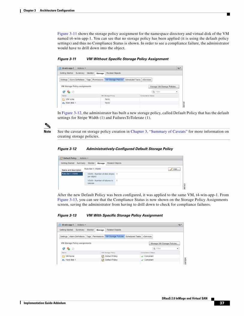
Figure 3-11 shows the storage policy assignment for the namespace directory and virtual disk of the VM named t4-win-app-1. You can see that no storage policy has been applied (it is using the default policy settings) and thus no Compliance Status is shown. In order to see a compliance failure, the administrator would have to drill down into the object.
Figure 3-11 VM Without Specific Storage Policy Assignment
In Figure 3-12, the administrator has built a new storage policy, called Default Policy that has the default settings for Stripe Width (1) and FailuresToTolerate (1).
Note See the caveat on storage policy creation in Chapter 3, “Summary of Caveats” for more information on creating storage policies.
Figure 3-12 Administratively-Configured Default Storage Policy
After the new Default Policy was been configured, it was applied to the same VM, t4-win-app-1. From Figure 3-13, you can see that the Compliance Status is now shown on the Storage Policy Assignments screen, saving the administrator from having to drill down to check for compliance failures.
Figure 3-13 VM With Specific Storage Policy Assignment
37DRaaS 2.0 InMage and Virtual SAN
Implementation Guide Addedum

Chapter 3 Architecture Configuration
Non-Default Storage Policy
For the critical management VMs of the InMage ScoutCloud deployment (e.g., MT), a non-default storage policy was created and applied. The settings for this non-default policy are summarized in Table 3-7.
DRaaS Application Suite
Project Environment ConfigurationThis project consisted of an Enterprise data center and an SP data center. No requirement exists for a specific Enterprise data center architecture for DRaaS 2.0 except for an edge device capable of being an OTV endpoint. For this project, however, the Enterprise DC was built as a tenant in a Cisco VMDC 2.2 multi-tenant test bed. For DRaaS 2.0, the SP data center is specified as being built on top of a Cisco VMDC VSA 1.0-based data center. In the case of this project, a single Bronze tenant (see Figure 3-4 on page 3-27) was used. The InMage ScoutCloud application suite, along with VMware Virtual SAN, was built on top of these two—Enterprise and SP—data center architectures, as depicted roughly in Figure 3-14.
Table 3-7 Critical VM Storage Policy Settings
Policy Value
Number of Disk Stripes Per Object 2
Flash Read Cache Reservation 0%
Number of Failures to Tolerate 2
Force Provisioning Disabled
Object Space Reservation 0%
38DRaaS 2.0 InMage and Virtual SAN
Implementation Guide Addedum

Chapter 3 Architecture Configuration
Figure 3-14 DRaaS Project Data Center Environment
Concerning the Enterprise Tenant in the above architecture:
• A three-tier application was built, including Web, App, and Database tiers.
– In the Web tier, three VMs on the 8.1.1.0/24 network existed.
– In the App tier, three VMs on the 8.1.2.0/24 network existed.
– In the DB tier, two VMs on the 8.1.3.0/24 network existed.
• A CSR 1000V was deployed as the Enterprise Edge device and configured as an OTV endpoint. The interfaces configured on the CSR 1000V included:
– Three separate interfaces for the Web, App, and DB networks.
– An OTV Overlay interface.
– An L2 trunk interface over which to carry the L2-extended VLANs.
– A management interface.
• A local InMage Process Server (PS) VM installation with interfaces on both the inband (8.1.1.0/24) and out-of-band (192.168.60.0/24) networks.
• All VMs in the Enterprise tenant were deployed using EMC VNX storage.
• Out-of-band network, 192.168.60.0/24.
• (Not shown) vSphere version 5.1 vCenter.
• (Not shown) Cisco Nexus 1000V deployed as the virtual switch.
Concerning the CSP IaaS instance configured for the Enterprise tenant:
• A Bronze container from a VMDC VSA 1.0 data center.
• A CSR 1000V deployed specifically as an OTV endpoint for the Enterprise tenant for L2 extension, with the same interfaces as for the Enterprise tenant.
Enterprise Tenant
Cloud Service Provider
2964
96
OTV
DRaaS Tenant 1
Mgmt (192.168.101.0/24)
8.1.1.0/24
11.1.5.186.68.1.6
cvf6-t4-csr
cvf1-sp4-csr
.33
8.1.1.1
.101
.32
.252
Mgmt (192.168.60.0/24)
.31
.253
.131
8.1.1.0/24
.101
.102
.103
.251 .1
.44
8.1.2.0/24
.101
.102
.103
8.1.3.0/24
.101
.102
cvf1-t4 im-mtp
.1
.1
t4-w
in-d
b-2
t4-w
in-d
b-1
t4-w
in-a
pp-3
t4-w
in-a
pp-2
t4-w
in-a
pp-1
t4-w
in-w
eb-3
cvf6
-t4-
im-p
s
t4-w
in-w
eb-2
t4-w
in-w
eb-1
cvf1-t4 im-ps cvf1-sp4 im-mtVM
39DRaaS 2.0 InMage and Virtual SAN
Implementation Guide Addedum

Chapter 3 Architecture Configuration
• A local InMage Process Server (PS) installation with interfaces on both the inband and OOB networks.
• An InMage MT installation.
• An InMage Multi-Tenant Portal (MTP) for multi-tenant manageability of DRaaS replication tasks.
• All VMs in the CSP were deployed using VMware Virtual SAN storage.
• Out-of-band network, 192.168.101.0/24.
• (Not shown) vSphere version 5.5 vCenter.
• (Not shown) VMware Virtual SAN cluster and datastore.
• (Not shown) Cisco Nexus 1000V deployed as the virtual switch.
Note The InMage ScoutCloud architecture allows for component redundancy for resiliency. This project did not take advantage of these redundancy options. For instance, in many installations, as mentioned above, an MT would be installed both in the CSP and in the Enterprise tenant so that recovery disks (VMDKs) could be mounted on a local machine. For this project, a single MT was deployed, residing in the CSP.
OTV ConsiderationsOverlay Transport Virtualization (OTV) is a critical technology in the DRaaS 2.0 solution, providing Layer 2 extension between the Enterprise and CSP or between two CSP sites, depending on the use case. The following information is necessary for understanding how to tune the InMage ScoutCloud deployment to work optimally in an OTV-enabled environment.
InMage Replication over OTV
OTV is an IP-based functionality designed to provide Layer 2 extension capabilities over any transport infrastructure whether Layer 2-based, Layer 3-based, IP-switched, label-switched, etc. The only requirement from the transport infrastructure is to provide IP connectivity between remote data center sites. OTV enables Layer 2 connectivity between separate Layer 2 domains while keeping these domains independent and preserving the fault-isolation, resiliency, and load-balancing benefits of an IP-based interconnection. OTV can be thought of as MAC-address routing, in which destinations are MAC addresses and next hops are IP addresses. OTV simply maps MAC address destinations to IP next hops that are reachable through the network cloud. Traffic destined for a particular MAC address is encapsulated in IP and carried through the IP cloud to its MAC address routing next hop. OTV encapsulates the MAC frame in an IP/UDP packet.
Multiple VLANs were extended over OTV between data centers for this testing. Figure 3-15 shows a CSR 1000V deployment with three server VLANs having one Layer 2 and one Layer 3 interface in each server VLAN. The first server VLAN was used for all of the replication traffic flowing between the SP and the Enterprise environments.
40DRaaS 2.0 InMage and Virtual SAN
Implementation Guide Addedum

Chapter 3 Architecture Configuration
Figure 3-15 OTV Data Center
Adjusting the Maximum Transmission Unit (MTU) on the PS Server
MTU consideration is critical when the WAN provider only supports an MTU of 1500 Bytes. By default, the PS server uses an IP MTU of 1500 bytes. During testing, packets of this size were observed when the PS server was performing an initial synchronization. Initial sync requires large amounts of data to be transmitted across the WAN link and large packets are used for efficiency. If the WAN uses encapsulation or encryption, the MTU of 1500 bytes may be too small for the WAN link and packets may need to be fragmented. This could result in lower throughput and performance issues.
In the tested topology, OTV with encryption was used between the Enterprise and Cloud SP sites. A CSR 1000V router was deployed at each site and the OTV link was configured between the two CSR 1000V routers. The OTV header consumed 42 bytes: Ethernet (14 bytes) + IP (20 bytes) + GRE (4 bytes) + MPLS (4 bytes).
In addition to the OTV encapsulation, encryption was also used to protect customer data. The encryption was allocated 86 bytes, although the configuration only consumed 62 bytes. Therefore, the 42 + 86 =128 bytes of overhead reserved for the CSR 1000V.
In the tested topology then (seen in Figure 3-14 on page 3-39), when the default MTU (1500 bytes) was configured on the PS server, the CSR 1000V had to fragment packets coming from the PS server during the initial sync. This resulted in low throughput across the WAN and increased the amount of time for the synch to complete. To avoid this scenario, the MTUs on the PS servers were lowered to 1372 bytes (1500 - 128) to accommodate the overhead used by the CSR 1000V.
In order to change the MTU on the PS Server, the root login/password is required, which is provided in the InMage documentation. After logging in as root, the MTU can be viewed using ifconfig in a terminal session. See Figure 3-16.
VLAN 2 VLAN 3VLAN 1
802.
1q
802.
1q
L3-V
LAN
2
802.
1qL3
-VLA
N1
L3-V
LAN
3
2947
52
CSR 1000V
Nexus 1000V
WAN/PE
CSR 1000V• LISP TR• L3 Gateway• OTV Edge• Ipsec• eBGP
802.1q Trunk – OTV Internal InterfaceL3 – Default Gateway
UplinkOTV Join Interface
WAN
VMDC Network Container
41DRaaS 2.0 InMage and Virtual SAN
Implementation Guide Addedum

Chapter 3 Architecture Configuration
Figure 3-16 NIC MTU Settings
The MTU can be changed at the command line, but those changes will not persist through a reboot of the VM. To change the MTU properly, the appropriate interface configuration file in /etc/sysconfig/network-scripts/ should be edited and the command mtu 1372 line appended to the file.
Figure 3-17 Edit MTU
Once the edits are complete, the networking can be restarted using the service network restart command. The change can be verified by again using the ifconfig command.
Disabling TCP Segmentation Offload and Large Receive Offload on PS Servers
In order to increase throughput of TCP traffic, a source host CPU can bypass the segmentation of large units of data (e.g., 64kB or 65,536 bytes) and rely on the network interface to perform the segmentation. This technique is called TCP Segmentation Offload (TSO) and decreases the CPU overhead while increasing the overall output throughput.
At the receiving side, the counterpart of TSO is called Large Receive Offload (LRO). The incoming packets are buffered by the network interface and passed up the network stack once the larger unit of data is received. A performance gain is realized since the CPU has fewer packets to process.
In the VMware vSphere environment, it is possible for TSO and LRO to cause significant performance degradation. This can occur when both the sending and receiving VMs reside on the same ESXi host. The sending host CPU may use TSO and expect that the network interface will perform the TCP segmentation, but the network interface does not perform this step. The large packets are delivered to the receiving VM. This scenario is specific to the two VMs being on the same host. If the receiving VM resides on a second ESXi host, this issue will not be observed.
In the test topology, we observed this scenario with the InMage PS server and the CSR 1000V. The PS server and CSR 1000V resided on the same host in the Enterprise data center. During the initial sync by InMage, the PS server collected data from the protected VM and sent the data across the WAN link by way of the OTV link on the CSR 1000V. The PS server sent the large data unit, and we observed the CSR 1000V dropping the packet. Use the show platform command, shown below, to view these drops on the CSR 1000V.
cvf6-t1#show platform hardware qfp active statistics drop -------------------------------------------------------------------------Global Drop Stats Packets Octets -------------------------------------------------------------------------Disabled 173 19588 FirewallInvalidZone 8238 692285 FirewallL4 31255 3438050 L2BDSourceFilter 56781862 63724490841 Layer2NoRoute 12 1275
42DRaaS 2.0 InMage and Virtual SAN
Implementation Guide Addedum
Chapter 3 Architecture Configuration
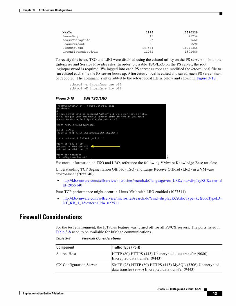
MaxTu 1976 5310229 ReassDrop 19 28234 ReassNoFragInfo 23 1662 ReassTimeout 38 1590 UidbNotCfgd 147434 16778366 UnconfiguredIpv6Fia 11052 1801680
To rectify this issue, TSO and LRO were disabled using the ethtool utility on the PS servers on both the Enterprise and Service Provider sites. In order to disable TSO/LRO on the PS server, the root login/password is required. We logged into each PS server as root and modified the /etc/rc.local file to run ethtool each time the PS server boots up. After /etc/rc.local is edited and saved, each PS server must be rebooted. The command syntax added to the /etc/rc.local file is below and shown in Figure 3-18.
ethtool -K interface tso offethtool -K interface lro off
Figure 3-18 Edit TSO/LRO
For more information on TSO and LRO, reference the following VMware Knowledge Base articles:
Understanding TCP Segmentation Offload (TSO) and Large Receive Offload (LRO) in a VMware environment (2055140)
• http://kb.vmware.com/selfservice/microsites/search.do?language=en_US&cmd=displayKC&externalId=2055140
Poor TCP performance might occur in Linux VMs with LRO enabled (1027511)
• http://kb.vmware.com/selfservice/microsites/search.do?cmd=displayKC&docType=kc&docTypeID=DT_KB_1_1&externalId=1027511
Firewall ConsiderationsFor the test environment, the IpTables feature was turned off for all PS/CX servers. The ports listed in Table 3-8 need to be available for InMage communications.
Table 3-8 Firewall Considerations
Component Traffic Type (Port)
Source Host HTTP (80) HTTPS (443) Unencrypted data transfer (9080) Encrypted data transfer (9443)
CX Configuration Server SMTP (25) HTTP (80) HTTPS (443) MySQL (3306) Unencrypted data transfer (9080) Encrypted data transfer (9443)
43DRaaS 2.0 InMage and Virtual SAN
Implementation Guide Addedum

Chapter 3 Architecture Configuration
Deploying Application VMs on the Virtual SAN DatastoreIn the CSP site, with VMware Virtual SAN providing the storage, all of the VMs needed for the InMage application were deployed on the Virtual SAN cluster. To summarize, here are the specifics of the Virtual SAN configuration once again:
• Three ESXi hosts running version 5.5.
• Virtual SAN datastore made of twelve 1 TB spindles and three 400 GB SSDs.
• A total datastore capacity of 12.3 TB (raw).
• Virtual SAN default policies set, including Stripe Width of 1 and FailuresToTolerate of 1.
• VMware Distributed Resource Scheduler (DRS) functionality enabled and configured for Automatic.
• VMware High Availability (HA) feature disabled.
Note VMware HA is certainly an option for Virtual SAN deployments. It was not used in this project due to the inherent resiliency that Virtual SAN provides and the fact that the project environment was limited to three nodes. In a four-node Virtual SAN cluster, HA would be a suitable choice.
Virtual SAN Component Distribution
In Chapter 3, “Technology Overview,” we looked at how Virtual SAN created distributed RAID trees for the VM storage objects that it manages. Figure 3-13 on page 3-21 provided a hypothetical look at how those objects and their subcomponents might be distributed on a 5-node Virtual SAN cluster. Figure 3-19 looks at one of the VMs deployed on the Virtual SAN cluster used at the CSP site when three nodes were used in this project. Because this VM was powered down at the time of this test, no SWAP file exists. Nor had any snapshots been taken of this VM. Therefore, the only storage objects belonging to this VM were the Namespace and the VMDK Disk.
Target Host HTTP (80) HTTPS (443) VX replication data traffic (873) FX replication (874) Unencrypted data transfer (9080) Encrypted data transfer (9443)
Optional SNMP 162
Process Server MySQL (3306) Unencrypted data transfer (9080) Encrypted data transfer (9443)
Table 3-8 Firewall Considerations (continued)
Component Traffic Type (Port)
44DRaaS 2.0 InMage and Virtual SAN
Implementation Guide Addedum

Chapter 3 Architecture Configuration
Figure 3-19 Virtual SAN Distributed RAID Tree, FTT=1 and Stripe Width=1
With Stripe Width=1, no striping occurs across spindles; Each duplicate of the Virtual SAN object is written to a single MD. In Figure 3-19, then, each object has a single RAID-1 group, consisting of two copies of the object data, the Comp(onent) in the illustration. One of those data copies is active, depicted in yellow in the illustration. Each object has a single witness in this scenario, to arbitrate potential active-active conflicts.
If this VM were powered on, there would be an additional RAID-1 object for swap. If snapshots had been taken of this VM, there would be additional RAID-1 objects for each of the delta disks, one per snapshot.
Using the Ruby vSphere Console (RVC) Virtual SAN commands, we can see the structure of the RAID tree and the distribution of these components across hosts and MDs. The vsan.vm_object_info command was used to explore the structure of the storage objects belonging to a VM called NewVM which was powered off with no snapshots.
/localhost/VSAN-DC/computers/VSAN Cluster> vsan.vm_object_info ../../vms/NewVM/2014-04-23 14:49:46 +0000: Fetching VSAN disk info from 192.168.13.23 (may take a moment) ...2014-04-23 14:49:46 +0000: Fetching VSAN disk info from 192.168.13.21 (may take a moment) ...2014-04-23 14:49:46 +0000: Fetching VSAN disk info from 192.168.13.22 (may take a moment) ...2014-04-23 14:49:47 +0000: Done fetching VSAN disk infos
VM NewVM: Namespace directory DOM Object: b3d15753-4cc3-db86-45ad-0025b5c262cc (owner: 192.168.13.21, policy: hostFailuresToTolerate = 1) Witness: b4d15753-6e46-06d2-568f-0025b5c262cc (state: ACTIVE (5), host: 192.168.13.22, md: naa.600605b006f7dae01ab65f7317f942d1, ssd: naa.600605b006f7dae01abde7e20e633fb2) RAID_1 Component: b4d15753-52a2-05d2-0475-0025b5c262cc (state: ACTIVE (5), host: 192.168.13.21, md: naa.600605b006f7fb701ab654db583860a1, ssd: naa.600605b006f7fb701abde07e0de6c455) Component: b4d15753-3a65-04d2-a98d-0025b5c262cc (state: ACTIVE (5), host: 192.168.13.23, md: naa.600605b006f7f9701ab603b21e8eff9d, ssd: naa.600605b006f7f9701abe00d3102940d7) Disk backing: [vsanDatastore] b3d15753-4cc3-db86-45ad-0025b5c262cc/NewVM.vmdk DOM Object: b9d15753-8a7a-33af-324a-0025b5c262cc (owner: 192.168.13.23, policy: hostFailuresToTolerate = 1, proportionalCapacity = 100) Witness: b9d15753-20da-4dbc-d7c0-0025b5c262cc (state: ACTIVE (5), host: 192.168.13.21, md: naa.600605b006f7fb701ab654db583860a1, ssd: naa.600605b006f7fb701abde07e0de6c455) RAID_1 Component: b9d15753-b4ad-4cbc-70be-0025b5c262cc (state: ACTIVE (5), host: 192.168.13.23, md: naa.600605b006f7f9701ab603db21047437, ssd: naa.600605b006f7f9701abe00d3102940d7)
2964
98
192.168.13.21 192.168.13.22 192.168.13.23
MD
1
MD
1
MD
1
MD
2
MD
2
MD
2
MD
3
MD
3
MD
3
MD
4
MD
4
MD
4
Comp
CompComp
Witness
RAID 1
Witness Comp
RAID 1
VM: Namespace VM: Disk
45DRaaS 2.0 InMage and Virtual SAN
Implementation Guide Addedum

Chapter 3 Architecture Configuration
Component: b9d15753-04d4-4abc-3237-0025b5c262cc (state: ACTIVE (5), host: 192.168.13.22, md: naa.600605b006f7dae01ab65f7317f942d1, ssd: naa.600605b006f7dae01abde7e20e633fb2)
The Namespace and Disk objects have been highlighted (boldface) for clarity. Each of these objects has a RAID tree consisting of RAID-1 duplication of data as components. The output from this RVC command provides information on which MDs the components are written to, which host owns the storage object, where the witnesses exist, what the relevant policies are (notice hostFailuresToTolerate values in the output, and the SSDs that are front-ending the I/O for each disk for a particular component.
Note One piece of information this command does not reveal is which of the object's duplicates are actually active and used by the VM. For this information, use the vsan.disk_object_info disk_uuid command, which is referenced in Virtual SAN Command Line Commands, page 3-1. This command will return all VMs and objects, using asterisks (**) to signify the active components.
Another way to view this output is to place it in a table showing the components, the RAID sets, and the hosts on which they reside. Table 3-9 gives such a view for the VMDK Disk object.
Using Table 3-9, we can evaluate the witness component placement in light of the witness deployment rules covered in Chapter 3, “Technology Overview.” When the witness calculation-based on those three rules-is performed in this scenario, the witness logic comes into play as below:
• Primary Witnesses—The data components are spread over only 2 nodes (which is not greater than 2*FTT+1), so we need to deploy a primary witness on the excluded node to achieve 2*FTT+1.
• Secondary Witnesses—With the addition of the Primary Witness, each node now has one component and equal voting power, so no Secondary Witnesses are needed.
• Tiebreaker Witness—With the addition of the Primary Witness, there already an odd number of total components, so no Tiebreaker Witness is needed.
Through the vSphere web client, we can see the RAID tree by exploring the VM, and drilling down into Manage > VM Storage Policies, as in Figure 3-20. Here, for the VMDK Disk object, we see the RAID tree with the data object duplicated across two hosts (written to a single disk in each).
Table 3-9 VM Storage Object View in Table, FTT=1 and Stripe Width=1
Type Component State Host SSD Disk Name MD Disk Name
Witness Active 192.168.13.21 naa.*6c455 naa.*860a1
RAID 1
Component Active 192.168.13.23 naa.*940d7 naa.*47437
Component Active 192.168.13.22 naa.*33fb2 naa.*942d1
46DRaaS 2.0 InMage and Virtual SAN
Implementation Guide Addedum

Chapter 3 Architecture Configuration
Figure 3-20 vSphere Web Client VM Storage Object View
For the sake of further explanation and demonstration, the Stripe Width policy was set to 2 for this VM. The object scheme shown in Figure 3-21 is the resultant layout for the new RAID tree.
47DRaaS 2.0 InMage and Virtual SAN
Implementation Guide Addedum

Chapter 3 Architecture Configuration
Figure 3-21 Virtual SAN Distributed RAID Tree, FTT=1 and Stripe Width=2
Several key changes should be noted, including:
• The Namespace RAID tree has not changed in character. It is still being handled as if Stripe Width=1. As mentioned in Chapter 2 above, the namespace and delta-disk objects will retain this striping policy regardless of what the administrator configures. These objects are not performance limited and therefore do not really benefit from having data striped across multiple spindles.
• The Disk (VMDK) RAID tree now includes two RAID-0 branches to handle the component striping across the spindles. Each component-the duplicate of the VMDK disk data-that had previously been written to a single MD is now written across two MDs.
• The VMDK Disk data is striped across MDs belonging to the same host. It is possible, with Virtual SAN, for striping to happen between MDs on different hosts as well.
• Three witnesses exist for the VMDK Disk object, due to the striping and MD distribution.
For our NewVM, we created a new storage policy with FailuresToTolerate=1 and Stripe Width=2 and applied it as shown in Figure 3-22.
Figure 3-22 Applying a Stripe Width=2 Policy to an Existing VM
192.168.13.21 192.168.13.22 192.168.13.23
MD
1
MD
1
MD
1
MD
2
MD
2
MD
2
MD
3
MD
3
MD
3
MD
4
MD
4
MD
4
2964
99
Comp
Comp
Comp
Witness
RAID 1
Witness
Comp
RAID 0 RAID 0
RAID 1
cvf1-wshark: Namespace cvf1-wshark: Disk
WitnessWitness
Comp
Comp
48DRaaS 2.0 InMage and Virtual SAN
Implementation Guide Addedum

Chapter 3 Architecture Configuration
The RVC command output following this change, which is shown below, can be compared to the output above where the striping was set to 1. Notice that the RAID tree has not changed shape for the Namespace object, for the reasons explained above. Notice also that the VMDK Disk object now has the RAID-1 group split into two RAID-0 branches, with the components striped across multiple spindles (across multiple hosts in one case).
/localhost/VSAN-DC/computers/VSAN Cluster> vsan.vm_object_info ../../vms/NewVM/VM NewVM: Namespace directory DOM Object: b3d15753-4cc3-db86-45ad-0025b5c262cc (owner: 192.168.13.21, policy: hostFailuresToTolerate = 1, stripeWidth = 1, spbmProfileId = 84fb64de-2308-4214-b4d5-6024e6f3b523, proportionalCapacity = [0, 100], spbmProfileGenerationNumber = 0) Witness: 80d95753-a67e-6264-5291-0025b5c262cc (state: ACTIVE (5), host: 192.168.13.22, md: naa.600605b006f7dae01ab65f7317f942d1, ssd: naa.600605b006f7dae01abde7e20e633fb2) RAID_1 Component: b4d15753-52a2-05d2-0475-0025b5c262cc (state: ACTIVE (5), host: 192.168.13.21, md: naa.600605b006f7fb701ab654db583860a1, ssd: naa.600605b006f7fb701abde07e0de6c455) Component: b4d15753-3a65-04d2-a98d-0025b5c262cc (state: ACTIVE (5), host: 192.168.13.23, md: naa.600605b006f7f9701ab603b21e8eff9d, ssd: naa.600605b006f7f9701abe00d3102940d7) Disk backing: [vsanDatastore] b3d15753-4cc3-db86-45ad-0025b5c262cc/NewVM.vmdk DOM Object: b9d15753-8a7a-33af-324a-0025b5c262cc (owner: 192.168.13.23, policy: spbmProfileGenerationNumber = 0, stripeWidth = 2, spbmProfileId = 84fb64de-2308-4214-b4d5-6024e6f3b523, hostFailuresToTolerate = 1) Witness: e1d95753-424a-6464-6924-0025b5c2622c (state: ACTIVE (5), host: 192.168.13.22, md: naa.600605b006f7dae01ab65f4b159bff8c, ssd: naa.600605b006f7dae01abde7e20e633fb2) Witness: e1d95753-f278-5e64-b8c8-0025b5c2622c (state: ACTIVE (5), host: 192.168.13.23, md: naa.600605b006f7f9701ab603db21047437, ssd: naa.600605b006f7f9701abe00d3102940d7) Witness: e1d95753-5c28-6264-2cb6-0025b5c2622c (state: ACTIVE (5), host: 192.168.13.22, md: naa.600605b006f7dae01ab65f7317f942d1, ssd: naa.600605b006f7dae01abde7e20e633fb2) RAID_1 RAID_0 Component: e1d95753-26e0-0448-6233-0025b5c2622c (state: ACTIVE (5), host: 192.168.13.21, md: naa.600605b006f7fb701ab654db583860a1, ssd: naa.600605b006f7fb701abde07e0de6c455, dataToSync: 0.00 GB) Component: e1d95753-6028-0248-bb0b-0025b5c2622c (state: ACTIVE (5), host: 192.168.13.21, md: naa.600605b006f7fb701ab6548453137d63, ssd: naa.600605b006f7fb701abde07e0de6c455, dataToSync: 0.00 GB) RAID_0 Component: e1d95753-622e-ff47-dca8-0025b5c2622c (state: ACTIVE (5), host: 192.168.13.23, md: naa.600605b006f7f9701ab603b21e8eff9d, ssd: naa.600605b006f7f9701abe00d3102940d7, dataToSync: 0.00 GB) Component: e1d95753-be88-f947-1472-0025b5c2622c (state: ACTIVE (5), host: 192.168.13.22, md: naa.600605b006f7dae01ab65f4b159bff8c, ssd: naa.600605b006f7dae01abde7e20e633fb2, dataToSync: 0.00 GB)
49DRaaS 2.0 InMage and Virtual SAN
Implementation Guide Addedum

Chapter 3 Architecture Configuration
Again, populating a table with the output data for the VMDK Disk object can provide greater clarity, as in Table 3-10.
Using Table 3-10, we can again evaluate the witness component placement in light of the witness deployment rules covered in Chapter 3, “Technology Overview.” When the witness calculation-based on those three rules-is performed in this scenario, the witness logic comes into play as below:
• Primary Witnesses—The data components are spread over all 3 nodes (which is equal to 2*FTT+1), so no primary witnesses are needed.
• Secondary Witnesses—Since one node (.21) has two votes and the other two nodes only have one vote each, we need to add a Secondary Witness on each of the other two nodes (.22 and .23).
• Tiebreaker Witness—With the addition of the two Secondary Witnesses, the total component is 6 (4 data + 2 witnesses). An even number of total components occurs, so a Tiebreaker Witness is needed and added on the .22 host.
The vSphere web client reflects this new storage policy, visualizing the new RAID tree for the VMDK Disk object, as shown in Figure 3-23.
Table 3-10 VM Storage Object View in Table, FTT=1 and Stripe Width=2
Type Component State Host SSD Disk Name MD Disk Name
Witness Active 192.168.13.22 naa.*33fb2 naa.*bff8c
Witness Active 192.168.13.23 naa.*940d7 naa.*47437
Witness Active 192.168.13.22 naa.*33fb2 naa.*942d1
RAID 1
RAID 0
Component Active 192.168.13.21 naa.*6c455 naa.*860a1
Component Active 192.168.13.21 naa.*6c455 naa.*37d63
RAID 0
Component Active 192.168.13.23 naa.*940d7 naa.*eff9d
Component Active 192.168.13.22 naa.*33fb2 naa.*bff8c
50DRaaS 2.0 InMage and Virtual SAN
Implementation Guide Addedum

Chapter 3 Architecture Configuration
Figure 3-23 vSphere Web Client VM Storage Object View Stripe Width=2
InMage Application Suite on Virtual SAN at CSP Site
As discussed in Chapter 3, “Technology Overview,” a complete InMage deployment will have several VMs built and configured at the CSP data center site, including the Master Target (MT), Multi-tenant Portal (MTP), and the local CX-PS server. While some of these have HA options available, this project did not deploy any DRaaS application-level redundancy.
We also mentioned Virtual SAN scalability in Chapter 3, “Technology Overview,” specifically the soft limits on the number of storage objects per ESXi host. At the time of this writing, with the initial release of Virtual SAN running, a soft limit of 3000 storage objects exists per ESXi host. Table 3-11 summarizes
51DRaaS 2.0 InMage and Virtual SAN
Implementation Guide Addedum
Chapter 3 Architecture Configuration
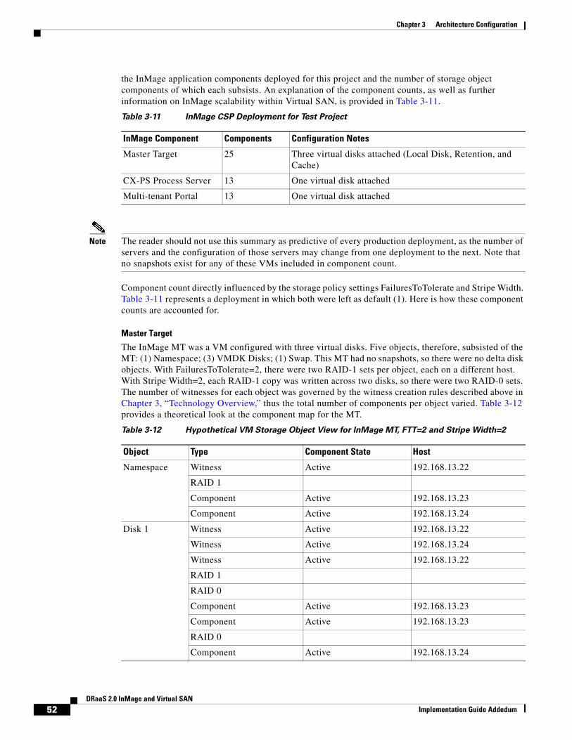
the InMage application components deployed for this project and the number of storage object components of which each subsists. An explanation of the component counts, as well as further information on InMage scalability within Virtual SAN, is provided in Table 3-11.
Note The reader should not use this summary as predictive of every production deployment, as the number of servers and the configuration of those servers may change from one deployment to the next. Note that no snapshots exist for any of these VMs included in component count.
Component count directly influenced by the storage policy settings FailuresToTolerate and Stripe Width. Table 3-11 represents a deployment in which both were left as default (1). Here is how these component counts are accounted for.
Master Target
The InMage MT was a VM configured with three virtual disks. Five objects, therefore, subsisted of the MT: (1) Namespace; (3) VMDK Disks; (1) Swap. This MT had no snapshots, so there were no delta disk objects. With FailuresToTolerate=2, there were two RAID-1 sets per object, each on a different host. With Stripe Width=2, each RAID-1 copy was written across two disks, so there were two RAID-0 sets. The number of witnesses for each object was governed by the witness creation rules described above in Chapter 3, “Technology Overview,” thus the total number of components per object varied. Table 3-12 provides a theoretical look at the component map for the MT.
Table 3-11 InMage CSP Deployment for Test Project
InMage Component Components Configuration Notes
Master Target 25 Three virtual disks attached (Local Disk, Retention, and Cache)
CX-PS Process Server 13 One virtual disk attached
Multi-tenant Portal 13 One virtual disk attached
Table 3-12 Hypothetical VM Storage Object View for InMage MT, FTT=2 and Stripe Width=2
Object Type Component State Host
Namespace Witness Active 192.168.13.22
RAID 1
Component Active 192.168.13.23
Component Active 192.168.13.24
Disk 1 Witness Active 192.168.13.22
Witness Active 192.168.13.24
Witness Active 192.168.13.22
RAID 1
RAID 0
Component Active 192.168.13.23
Component Active 192.168.13.23
RAID 0
Component Active 192.168.13.24
52DRaaS 2.0 InMage and Virtual SAN
Implementation Guide Addedum

Chapter 3 Architecture Configuration
Process Server and Multi-tenant Portal
Because both the InMage PS and the MTP were configured similarly, with a single virtual disk, the following explanation applies equally. Each of these servers had three objects: (1) Namespace; (1) VMDK Disks; (1) Swap. There were no snapshots, so there were no delta disk objects. With FailuresToTolerate=2, there were two RAID-1 sets per object, each on a different host. With Stripe Width=2, each RAID-1 copy was written across two disks, so there were two RAID-0 sets. The number
Component Active 192.168.13.24
Disk 2 Witness Active 192.168.13.23
Witness Active 192.168.13.24
Witness Active 192.168.13.23
RAID 1
RAID 0
Component Active 192.168.13.21
Component Active 192.168.13.21
RAID 0
Component Active 192.168.13.24
Component Active 192.168.13.23
Disk 3 Witness Active 192.168.13.22
Witness Active 192.168.13.22
Witness Active 192.168.13.24
RAID 1
RAID 0
Component Active 192.168.13.24
Component Active 192.168.13.24
RAID 0
Component 192.168.13.23
Component 192.168.13.23
Swap Witness Active 192.168.13.22
RAID 1
Component Active 192.168.13.23
Component Active 192.168.13.21
Table 3-12 Hypothetical VM Storage Object View for InMage MT, FTT=2 and Stripe Width=2
Object Type Component State Host
53DRaaS 2.0 InMage and Virtual SAN
Implementation Guide Addedum

Chapter 3 Architecture Configuration
of witnesses for each object was governed by the witness creation rules described above in Chapter 3, “Technology Overview,” thus the total number of components per object varied. Table 3-13 provides a theoretical look at the component map for the InMage PS and MTP.
InMage Component Scalability on Virtual SAN
As mentioned above, the scalability of a given InMage DRaaS deployment will be directly related to the configuration of the InMage environment. The other factor governing scalability is servers that are being protected by the InMage DRaaS service running at the CSP. Just as with the InMage application nodes themselves, the configuration of the hosts that are protected by InMage will determine scalability within Virtual SAN.
This paper cannot predict absolute scalability and make definitive statements regarding the number of hosts that can be protected by InMage backed by a given Virtual SAN deployment. Instead, we will strive to provide the guidance needed for the administrators to predict scalability in their own, unique deployments. We therefore, offer the following guidelines.
Protection Plan Creation
When an InMage protection plan created, a replicate of the protected machine is deployed in the CSP, on the Virtual SAN cluster, using the Virtual SAN datastore. This replicate is powered off until a DR event occurs. The machine's disks will be replicated at the CSP, but until the DR event occurs, those VMDKs will be owned by the MT. Regardless, the VMDKs will consume components on the Virtual SAN datastore. With this in mind, the guidelines for scalability at the point at which the protection plan is created are as follows.
Table 3-13 Hypothetical VM Storage Object View for InMage PS & MTP, FTT=2 and Stripe
Width=2
Object Type Component State Host
Namespace Witness Active 192.168.13.22
RAID 1
Component Active 192.168.13.23
Component Active 192.168.13.24
Disk Witness Active 192.168.13.23
Witness Active 192.168.13.23
Witness Active 192.168.13.24
RAID 1
RAID 0
Component Active 192.168.13.21
Component Active 192.168.13.21
RAID 0
Component Active 192.168.13.24
Component Active 192.168.13.23
Swap Witness Active 192.168.13.21
RAID 1
Component Active 192.168.13.23
Component Active 192.168.13.22
54DRaaS 2.0 InMage and Virtual SAN
Implementation Guide Addedum

Chapter 3 Architecture Configuration
• Guideline #1—One Namespace object will exist per protected machine.
• Guideline #2—Regardless of the storage policy being used, the Namespace object will have Stripe Width=1 and FailuresToTolerate=1.
• Guideline #3—With Stripe Width=1, two components will be created for the Namespace object.
• Guideline #4—Following the rules for witness creation in Chapter 2, one witness will be created.
• Guideline #5—One object will be created per virtual disk on the machine.
• Guideline #6—The number of mirror copies created of each Disk object will be determined by the FailuresToTolerate policy, using the formula [#Copies = FTT + 1].
• Guideline #7—The number of components created for each of the Disk object copies will be governed by the Stripe Width policy, using the formula [#Components = #Copies * #Stripes].
• Guideline #8—Follow the rules for witness creation to determine the number of witness components that will be created.
• Guideline #9—No swap objects will be created until the machine is powered on, following the DR event.
• Guideline #10—None of the snapshots for the protected machine will be propagated to the InMage replicate, so no delta disk objects will exist.
Summary
On the CSP side, the machine that is protected will have, at this point, objects for its disks and namespace.
Recover Event
When the protection plan is invoked to recover Enterprise machines in the CSP, the replicate VMs in the CSP will take ownership of their VMDKs from the MT, and the VMs will be powered on. Each VM that is powered on will be assigned a swap file, which is subject to the Virtual SAN storage policies. The guidelines for scalability at the point at which a protected machine is recovered in the CSP are as follows.
• Guideline #1—All Disk and Namespace objects and components will remain the same as when the machine was initially protected.
• Guideline #2—A Swap object will be created for the recovered VM.
• Guideline #3—Regardless of the storage policy being used, the Namespace object will have Stripe Width=1 and FailuresToTolerate=1.
• Guideline #4— Stripe Width=1, two components will be created for the Namespace object.
• Guideline #5—Following the rules for witness creation in Chapter 2, one witness will be created.
Summary
The protected machine will add to its existing count three components for the Swap object when it is powered on.
Resume Protection
When the InMage administrator resumes protection for a given machine, the VM in the CSP will be powered down. When this happens, the Swap object is destroyed, reducing the component count for that protected machine by three, back to the original count at Protection Plan Creation.
55DRaaS 2.0 InMage and Virtual SAN
Implementation Guide Addedum
Chapter 3 Architecture Configuration
InMage Storage Scalability on Virtual SAN
We must mention in brief how storage consumption on the CSP Virtual SAN datastore is scaled. This, too, is governed by the VM storage policies being employed on the Virtual SAN cluster, specifically the FailuresToTolerate policy. When FTT=1, for example, two copies of the data are created. For a crude estimation, determine storage consumption using the following formula: [StorageUsed = DiskSize * (FTT + 1)]. For example, given a protected machine having one 20GB disk and FTT=1, 40GB of storage will be used. If a protected machine has three 100 GB disks and FTT=2, 900GB of storage will be used.
Note For a finer calculation, please use the Virtual SAN datastore calculate on Duncan Epping's blog: http://www.yellow-bricks.com/2014/01/17/virtual-san-datastore-calculator/
The storage consumed for non-Disk objects (including witnesses) is negligible, unless at very large scales. For example, a witness object consumes 2 MB of disk. This is not a big deal for a few VMs, but for hundreds of VMs and storage policies set to non-default values, it could add up.
56DRaaS 2.0 InMage and Virtual SAN
Implementation Guide Addedum