chapter 23 mortar ranges - … · a mortar range needs little, if any, permanent construction. ......
TRANSCRIPT

Any Copies of this Document, either Paper or Electronic are Uncontrolled Mortar Ranges
CHAPTER 23
JSP 403 Volume 2 Edition 3 Change 6
MORTAR RANGES INTRODUCTION
2301. General. A mortar range needs little, if any, permanent construction. Selection of the range and preparation of the firing points (mortar line) by the mortar detachment may be all that is required. However, on permanent training ranges it may be advantageous for some permanent construction to be undertaken. 2302. Training Area Status. The status of the training area for firing mortars depends on the ammunition nature:
a. HE and Smoke. These may only be fired on a designated range authorised in accordance with Reference A (Volume I). b. Para-Illuminating. This may be fired on a designated range or on military training areas subject to the approval of the RAU.
2303. Aim. This chapter describes the facilities that may be constructed on a mortar range and in particular:
a. Introduction 2301 - 2303 b. Range danger areas 2304 - 2306 c. Construction 2307 - 2310 d. Communications 2311 - 2312 e. Maintenance 2313
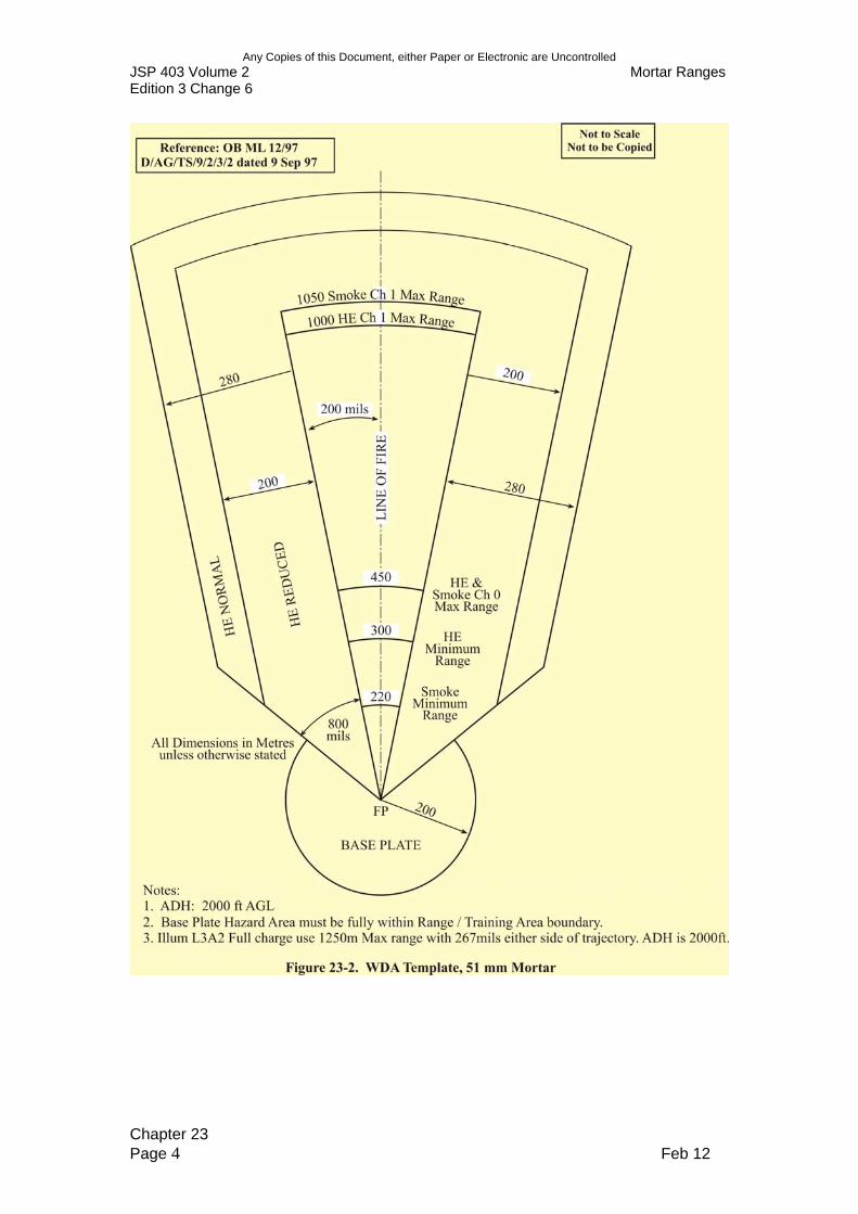
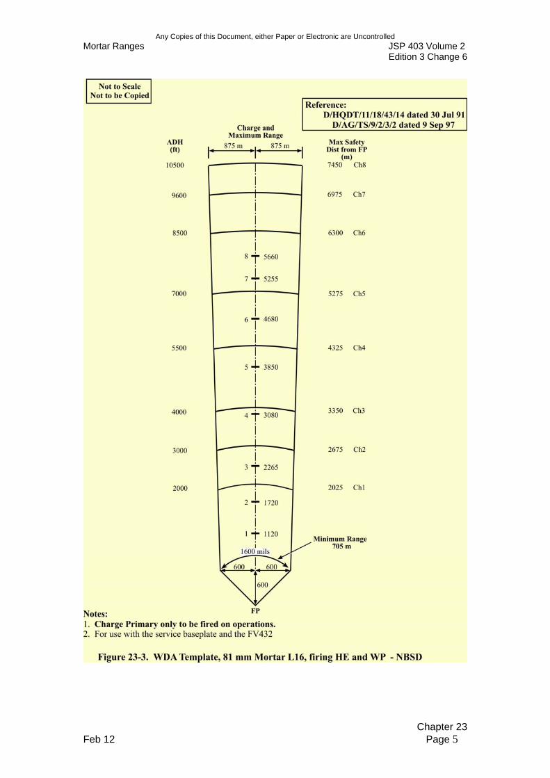
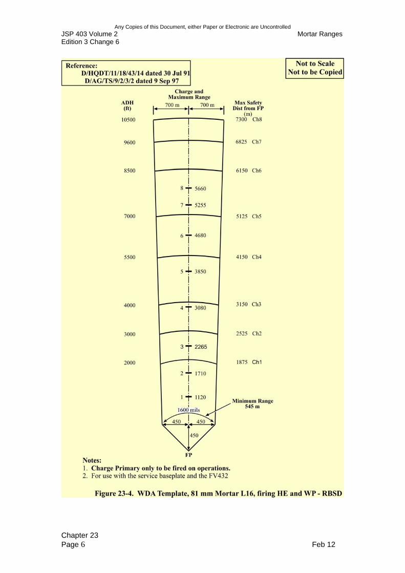
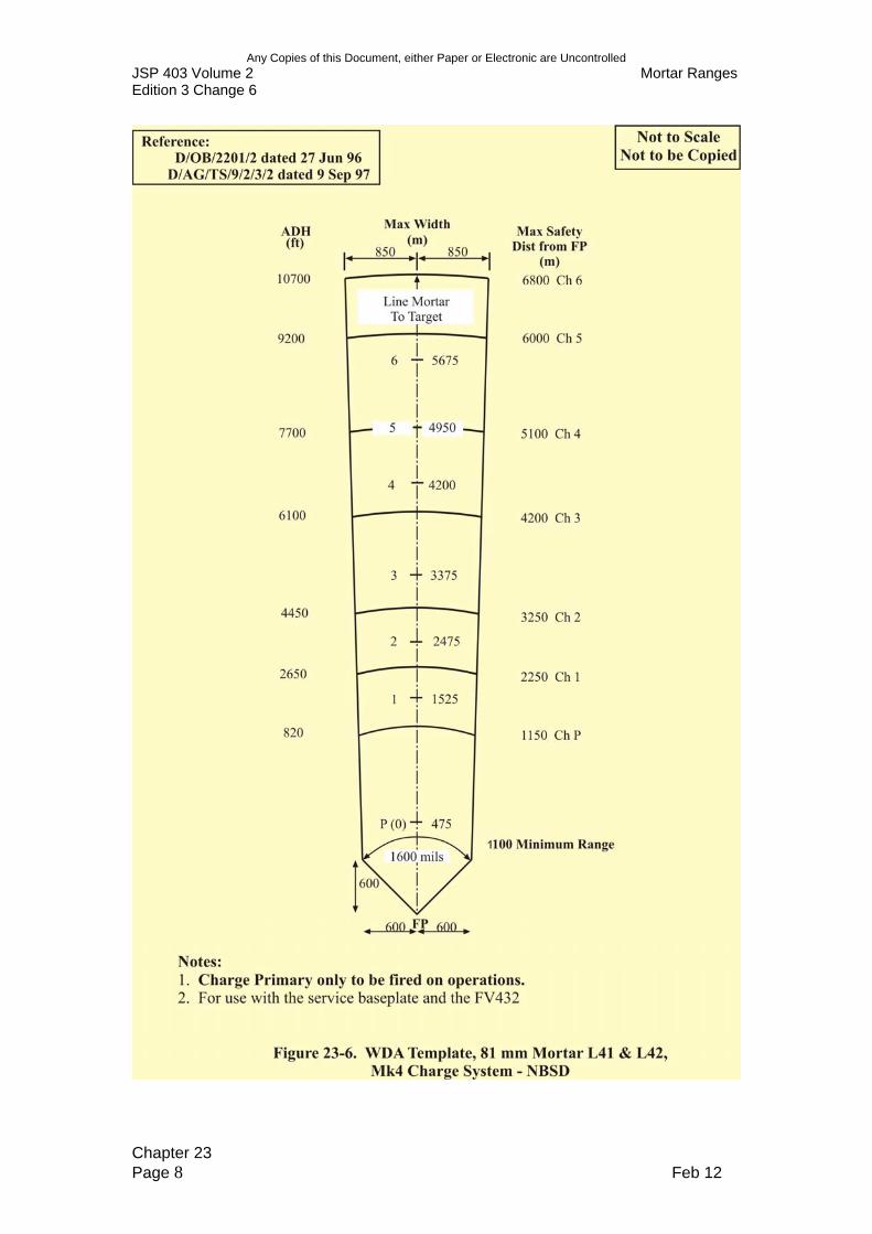
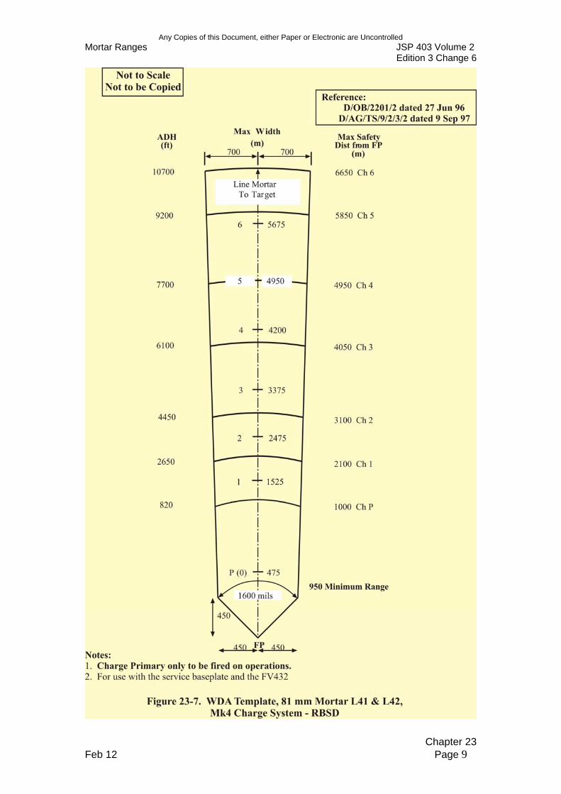
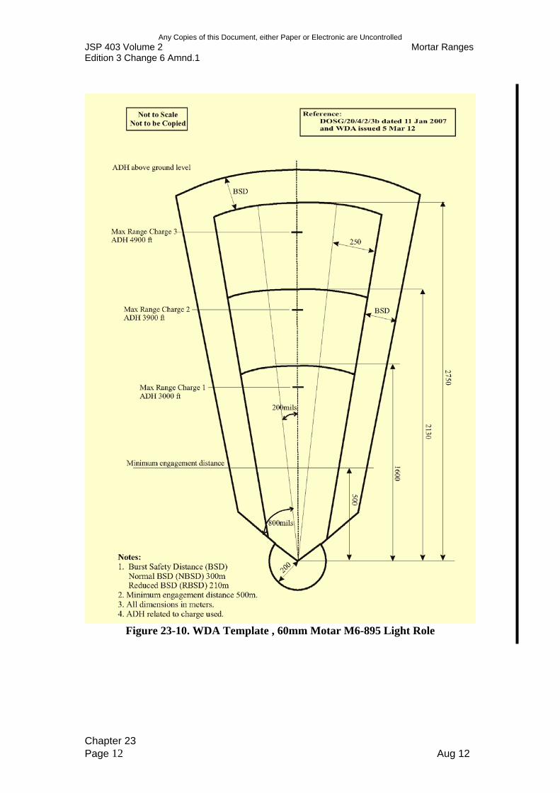
RANGE DANGER AREAS 2304. Weapon Danger Area Templates. The currently approved WDA templates for Light and Medium Mortars are shown in the Figures to this Chapter. The conditions for applying the templates are set out in Reference B (Pamphlet 21). However, the overhead mortar fire safety template (Figure 23-9) can only be used on ranges that permit this type of training (see Reference B (Pamphlet 21)). Any deviation in applying the WDA templates will require approval from HQ Infantry. 2305. Topography. At extreme ranges the difference in height between the firing position and the target has to be taken into account (see Reference B (Pamphlet 21)). 2306. Impact Areas. Refer to Chapter 2.
CONSTRUCTION 2307. Siting. The area selected for a mortar range has to contain the WDA and should be large enough to exercise the mortar platoon in fire and manoeuvre using, ideally, the maximum range of the weapons. The ADH and the requirement for notification as stated in Chapter 1 will need to be considered. In woodland, there must be sufficient muzzle clearance over the full arcs of fire at the mortar line.
Chapter 23 Feb 12 Page 1
Any Copies of this Document, either Paper or Electronic are Uncontrolled JSP 403 Volume 2 Mortar Ranges Edition 3 Change 6
2308. Targets. There are no specific targets for mortar ranges. They may be physical features, simulated defensive positions, figure targets or vehicles. The target area should be firm and dry ground to reduce the number of blinds. 2309. Mortar Fire Controller Positions. Mortar fire controller (MFC) positions on PTR may require prepared observation posts (OP) and surfaces for AFV. 2310. Mortar Lines. Tactically, mortars will be positioned 40 m apart but this may be reduced to 10 m if space is restricted. A permanent mortar line may require pre-positioned mortar positions and prepared sites or hides for AFV mounted mortars.
COMMUNICATIONS 2311. External. A means of summoning the emergency services, ideally a land laid telephone, is to be available. 2312. Internal. Radio or telephones must be provided between the RCO, MFC , mortar lines and range control. Permanent ranges will normally have their own range safety network.
MAINTENANCE 2326. Little maintenance is necessary on a mortar range. Constructed positions, such as MFC and dug-in firing positions, require to be inspected and kept in a safe state. Clearing undergrowth, dead wood, litter and debris reduces the fire risk.
Chapter 23 Page 2 Feb 12

Any Copies of this Document, either Paper or Electronic are Uncontrolled Mortar Ranges JSP 403 Volume 2
Edition 3 Change 6
Chapter 23 Feb 12 Page 3
Any Copies of this Document, either Paper or Electronic are Uncontrolled JSP 403 Volume 2 Mortar Ranges Edition 3 Change 6
Chapter 23 Page 4 Feb 12
Any Copies of this Document, either Paper or Electronic are Uncontrolled Mortar Ranges JSP 403 Volume 2
Edition 3 Change 6
Chapter 23 Feb 12 Page 5
Any Copies of this Document, either Paper or Electronic are Uncontrolled JSP 403 Volume 2 Mortar Ranges Edition 3 Change 6
Chapter 23 Page 6 Feb 12

Any Copies of this Document, either Paper or Electronic are Uncontrolled Mortar Ranges JSP 403 Volume 2
Edition 3 Change 6
Chapter 23 Feb 12 Page 7
Any Copies of this Document, either Paper or Electronic are Uncontrolled JSP 403 Volume 2 Mortar Ranges Edition 3 Change 6
Chapter 23 Page 8 Feb 12
Any Copies of this Document, either Paper or Electronic are Uncontrolled Mortar Ranges JSP 403 Volume 2
Edition 3 Change 6
Chapter 23 Feb 12 Page 9

Any Copies of this Document, either Paper or Electronic are Uncontrolled JSP 403 Volume 2 Mortar Ranges Edition 3 Change 6
Chapter 23 Page 10 Feb 12
Any Copies of this Document, either Paper or Electronic are Uncontrolled Mortar Ranges JSP 403 Volume 2
Edition 3 Change 6
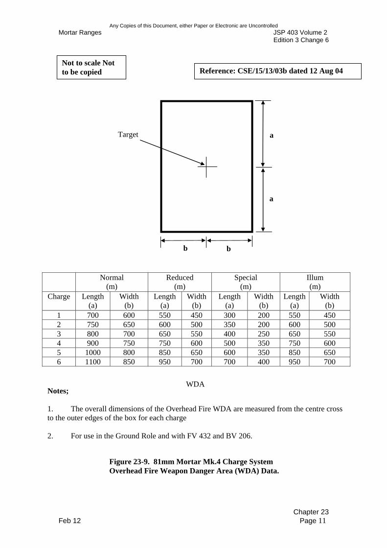
Not to scale Not to be copied Reference: CSE/15/13/03b dated 12 Aug 04
Target a
a
b b
Normal (m)
Reduced (m)
Special (m)
Illum (m)
Charge Length (a)
Width (b)
Length (a)
Width (b)
Length (a)
Width (b)
Length (a)
Width (b)
1 700 600 550 450 300 200 550 450 2 750 650 600 500 350 200 600 500 3 800 700 650 550 400 250 650 550 4 900 750 750 600 500 350 750 600 5 1000 800 850 650 600 350 850 650 6 1100 850 950 700 700 400 950 700
WDA Notes;
1. The overall dimensions of the Overhead Fire WDA are measured from the centre cross to the outer edges of the box for each charge
2. For use in the Ground Role and with FV 432 and BV 206.
Figure 23-9. 81mm Mortar Mk.4 Charge System Overhead Fire Weapon Danger Area (WDA) Data.
Chapter 23 Feb 12 Page 11
Any Copies of this Document, either Paper or Electronic are Uncontrolled JSP 403 Volume 2 Mortar Ranges Edition 3 Change 6 Amnd.1
Figure 23-10. WDA Template , 60mm Motar M6-895 Light Role
Chapter 23 Page 12 Aug 12
Any Copies of this Document, either Paper or Electronic are Uncontrolled Mortar Ranges JSP 403 Volume 2
Edition 3 Change 6 Amnd. 1
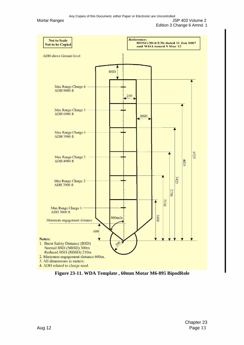
Figure 23-11. WDA Template , 60mm Motar M6-895 BipodRole
Chapter 23 Aug 12 Page 13
Any Copies of this Document, either Paper or Electronic are Uncontrolled JSP 403 Volume 2 Edition 3 Change 6
Mortar Ranges
Not to Scale Not to be Copied
Reference: DOSG/20/4/2/3 dated Sep 08
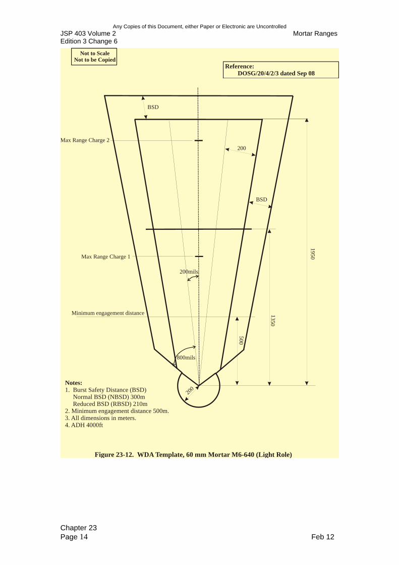
Notes: 1. Burst Safety Distance (BSD)
Normal BSD (NBSD) 300m Reduced BSD (RBSD) 210m
2. Minimum engagement distance 500m. 3. All dimensions in meters. 4. ADH 4000ft
200mils
1 950
1350
500
200
200
800mils
Minimum engagement distance
Max Range Charge 2
Max Range Charge 1
BSD
BSD
Figure 23-12. WDA Template, 60 mm Mortar M6-640 (Light Role)
Chapter 23 Page 14 Feb 12