chapter 21 wright state university - university of …nsf-pad.bme.uconn.edu/1999/chapter 21.pdf ·...
TRANSCRIPT

323
CHAPTER 21 WRIGHT STATE UNIVERSITY College of Engineering and Computer Science
Department of Biomedical and Human Factors Engineering Dayton, Ohio 45435-0001
Principal Investigator:
Chandler A. Phillips (937) 775-5044 [email protected]
David B. Reynolds (937) 775-5045

324 NSF 1999 Engineering Senior Design Projects to Aid Persons with Disabilities
LEARNING AUDIO DEVICE Designers: Benjamin R. Lucas, Anthony J. Ewald, and Russel A. Clark
Supervising Professor: Dr. Thomas N. Hangartner Department of Biomedical and Human Factors Engineering
Wright State University Dayton, OH 45435-0001
INTRODUCTION A teacher at a school for children with disabilities requested a modification of a toy to help foster learning of shape recognition. The students previously used a cylindrical plastic toy with three holes in its lid. The holes were square, triangular, and circular. The child dropped red, yellow, and blue plastic blocks corresponding to the holes in the cylinder as they learned to recognize different shapes and colors. Children frequently placed a shape at the opening of the correct hole but moved the block to another hole when it did not immediately fit. This was because the child was not holding the block in the correct orientation and did not have enough affirmation that the block was near the correct hole.
The teacher requested a similar toy that would emit a beeping sound when a block was above its corresponding hole. With this proximity feedback the child knows that the hole was correct and that the block must be rotated to the correct position. This process would encourage the child to concentrate on the configuration of the shape of the
block and the hole.
The teacher also requested an audio reward for the child when a block is successfully placed inside the toy. The success feedback was to be independent of the proximity sensing method. Additional specifications were that the toy be:
• Portable,
• Small enough to enable small children seated at a desk or table to see the whole lid,
• Battery powered to eliminate cords that might pose a tripping hazard, and
• Safe for use with small children, having no sharp edges, exposed electrical components, or small pieces that can be swallowed.
The learning audio device is illustrated in Figure 21.1, and shown in use in Figure 21.2.
SUMMARY OF IMPACT The learning audio device is safe and fun. There are a few recommendations for further work that would make this product more enjoyable and practical. Battery life is less than an hour, meaning frequent replacement by the user. Supplying the user with a 9-volt battery charger would reduce maintenance cost. For future development one could find ways
Figure 21.1. Learning Audio Device.
Figure 21.2. Children Safely Interacting With The Learning Audio Device.

Chapter 21: Wright State University 325
to reduce the overall power consumption to get more life out of the battery. Another recommendation would be to institute a means of audio volume control on the device. According to the evaluator, the design is thoughtful, as are the switch options. The easy-access collection box eliminates the need to open the box itself. The battery is easy to change. The instruction manual was reportedly very helpful.
TECHNICAL DESCRIPTION For proximity sensing, the method implemented is mutual inductive coupling. The basic physical concept behind this method is Faraday’s Law, which states that if an alternating current is sent through a (primary) wire, an electromagnetic field will be induced around the wire. The magnitude of this field is proportional to the frequency of the current (i.e. the derivative of the current with respect to time). If another (secondary) wire is brought within proximity of this field, energy will be transferred to it, and a current will be induced.
Winding both of the wires into coils capitalizes on this phenomenon while keeping the system compact. Each coil acts as a large inductor, with an inductance value (L) that depends on both the geometry of the coil and the number of windings. If a coil is then placed in parallel with a capacitor, the transfer of energy back and forth between the two components results in an oscillating system. The magnitude of energy transfer is maximized at a particular frequency, known as the resonant frequency. By varying the capacitor, the circuit can be “tuned” to any desired frequency. The circuitry is depicted in Figure 21.3.
Application of this method to the design involves attaching an active (power supplied) coil around each of the holes in the lid. A passive coil is placed inside the block. Each shape (in both the block and the lid) is tuned to a specific frequency so that when the coils are brought together, energy is transferred from the active coil to the passive one. Shapes can be differentiated by frequency modulation (e.g. the squares are tuned to 600 kHz, circles to 455 kHz, and triangles to 300kHz). The voltage change associated with the active coil is then used to trigger audio feedback. This means that the passive circuit (in the block) is only absorbing and dissipating power, and therefore requires no power supply in the blocks. Implementing this circuitry is inexpensive since wire
coils and passive components are readily available and inexpensive.
The proximity sensor relies on three different components:
• A measuring resistor,
• A half-wave rectifier, and
• A comparator.
The measuring resistor is placed in series with the RLC circuit, and when the coils are tuned, the voltage across the resistor is at its minimum because the voltage across the coils is at its maximum (Ohm’s Law).
When a tuned passive coil comes close to the active, it draws current from the active coil, which in turn increases the current in the circuit. By Ohm’s Law, this increases the voltage across the measuring resistor. This increase in AC voltage is then rectified and smoothed before it is sent to a comparator. An appropriate threshold voltage is input to the comparator also. This is done by constructing a voltage divider from the power source. When the input from the rectifier exceeds this threshold (i.e. when a block is brought near the correct hole), a high output pulse is sent to a piezoelectric beeper, producing the required feedback.
For the success sound, three different microswitches are mounted on the underside of the ramp inside the toy. The lever arms of these switches extend up through the holes in the ramp under each of the differently shaped holes. As the blocks fall through the lid of the toy, they strike the switches before hitting the ramp and sliding down into the collection bin. When the switches are thrown, they complete a circuit connecting the voltage supply to an audio chip that was extracted from a children’s book. Each momentary switch is connected to a different location on the chip, causing a different jingle for each shape. The schematic of these components is illustrated in Figure 21.3.
The finished toy is a small box constructed with poplar wood, stained with a red oak finish and sealed with polyurethane. All of the electrical components were connected using standard soldering techniques and IC sockets wherever possible. A computer-generated diagram of the circuitry is shown in Figure 21.4.

326 NSF 1999 Engineering Senior Design Projects to Aid Persons with Disabilities
The master switch is a red, three-position switch located on the side of the toy. When this switch is in the center position, the toy is off. When the switch is thrown toward the collection bin of the toy, only the success feedback is activated. When the switch is thrown in the other direction, both the proximity and success feedback systems are activated. When the toy is not in use, it is important that the switch be in the “off” (center) position. Leaving the toy on, especially when both success and proximity feedback are activated (i.e. the switch is away from the collection bin) will rapidly decrease the life of the batteries inside the toy.
In order to change the battery, the lid of the toy must be opened, exposing the inner success slope. After carefully lifting this slope (making sure the large wires to the lid area out of the way), the underlying circuitry can be seen. The battery holder is mounted
on the same side as the switch. The battery is placed so that the large terminal slides onto the small terminal on the holder. Finally, the battery is firmly put in place in full contact with the terminals of the holder.
The base can be rotated from side to side to vary the positions of the holes, but the collection bin should not be oriented toward the child. Giving the child a block with the indentation (grip) directed upward helps ensure correct vertical orientation and a good signal for proximity sensing. After the block has been put in the correct hole, it slides to the collection bin. The collection bin lid can be kept open to clear the ramp.
The overall cost of the learning audio device is $890.00.

Chapter 21: Wright State University 327
6.4nF .8nF 50nF22k 22k
1k
300kHz
-5/5V
22k
10nF
6.4nF .8nF 50nF22k 22k
1k
300kHz
-5/5V
22k
10nF
6.4nF .8nF 50nF22k 22k
1k
300kHz-5/5V
22k
10nF
2.2k
5k
2.2k
5k
2.2k
5k
-+
-+
-+
DC/DC Converter
+15v
-15v
IN
COM
7.2V78L05
COM
IN OUT
18
8
Figure 21.3. Circuit Schematic.
EPROM
SpeakerBattery
ProximityBeeperCircuitry for
On/Off switch
VoltageRegulator
TrimmingCapacitors (3)
VariableResistors (3)
Comparators(2)
Oscillators (3) Raised Circuit Board
Figure 21.4. Circuitry Diagram.

328 NSF 1999 Engineering Senior Design Projects to Aid Persons with Disabilities
WHEELCHAIR ADAPTED BARCODE SCANNER SYSTEM
Designers: Angeles Seibert and Mary Yinger Supervising Professor: Dr. Blair Rowley
Department of Biomedical and Human Factors Engineering Wright State University
Dayton, Ohio 45435-0001
INTRODUCTION A fifty-year old man with spastic cerebral palsy is employed at a home improvement warehouse. His employer would like him to scan barcodes on the shelves to check for incorrect prices. The client’s movement and posture disorder is characterized by increased muscle tone that results in movement difficulty. He uses a wheelchair and has moderate ataxia (shaking). The client’s ataxia makes it difficult to hold the bar code scanner steadily enough to scan a barcode. The client uses a Ranger X Storm Series wheelchair and his steering mechanism is located on the left side of his wheelchair. The barcode scanner is a Symbol Technology LRT 3800.
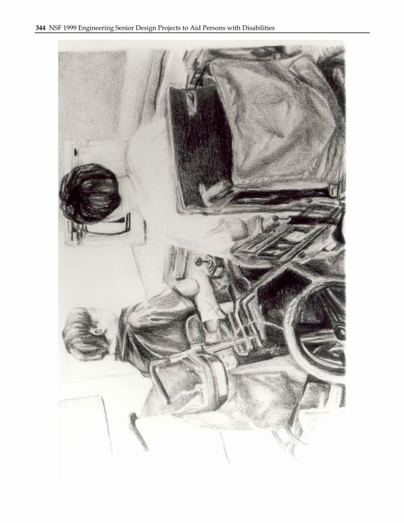
The purpose of this design was to create a system that securely attaches a barcode scanner to the client’s wheelchair without inhibiting use of the scanner or wheelchair. The system, depicted in Figure 21.5, must allow raising and lowering of the scanner as well as triggering of the scanner and data entry.
SUMMARY OF IMPACT The client was a very active part of the design process. The current system requires some physical exertion from the client. The repetitiveness of the exercise will increase his muscle tone and will improve his ability to use the system.
Unfortunately, the design is not as easy for the client to operate as originally intended. It is recommended that further work involving the scanner be achieved. Additionally, the scanner should be internally wired to a stereo jack located at the back of the scanner, allowing for a push button to be plugged into the jack to eliminate one rope from the system, which in turn would reduce some of the physical exertion required.
With a securely mounted scanner, the client is able to raise and lower the scanner, trigger the scanner and press the enter button, thus allowing him to perform his job duties successfully. The whole system can be easily removed from the wheelchair and the scanner can be easily removed from the system.
TECHNICAL DESCRIPTION The barcode system is constructed of ¾ inch PVC pipe. It measures 5 feet high, 10 inches across, and 5 inches deep. The entire system weight is less than 7 pounds without the scanner attached. There is a 4½- foot steel rod inserted into the PVC pipe to help keep the system from bending. The scanner is attached to a ½ inch thick wood backboard by Velcro straps. The scanner is raised and lowered by ropes and six 1” rigidly mounted pulleys. The scanner’s operating range is 14 to 55 inches from the floor. The system is not designed to lift more than 20 pounds.
To operate this system, the scanner is positioned into the upper cutout on the backboard. It is necessary
Figure 21.5. Bar Code Adapter System.
Chapter 21: Wright State University 329
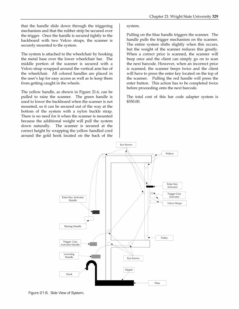
that the handle slide down through the triggering mechanism and that the rubber strip be secured over the trigger. Once the handle is secured tightly to the backboard with two Velcro straps, the scanner is securely mounted to the system.
The system is attached to the wheelchair by hooking the metal base over the lower wheelchair bar. The middle portion of the scanner is secured with a Velcro strap wrapped around the vertical arm bar of the wheelchair. All colored handles are placed in the user’s lap for easy access as well as to keep them from getting caught in the wheels.
The yellow handle, as shown in Figure 21.6, can be pulled to raise the scanner. The green handle is used to lower the backboard when the scanner is not mounted, so it can be secured out of the way at the bottom of the system with a nylon buckle strap. There is no need for it when the scanner is mounted because the additional weight will pull the system down naturally. The scanner is secured at the correct height by wrapping the yellow handled cord around the gold hook located on the back of the
system.
Pulling on the blue handle triggers the scanner. The handle pulls the trigger mechanism on the scanner. The entire system shifts slightly when this occurs, but the weight of the scanner reduces this greatly. When a correct price is scanned, the scanner will beep once and the client can simply go on to scan the next barcode. However, when an incorrect price is scanned, the scanner beeps twice and the client will have to press the enter key located on the top of the scanner. Pulling the red handle will press the enter button. This action has to be completed twice before proceeding onto the next barcode.
The total cost of this bar code adapter system is $550.00.
Enter Key ActivatorHandle
Raising Handle
Trigger GunActivator Handle
LoweringHandle
Hook
Plate
Nipple
Eye Screws
Pulley
Velcro Straps
Trigger GunActivator
Enter KeyActivator
Pulleys
Eye Screws
Figure 21.6. Side View of System.

330 NSF 1999 Engineering Senior Design Projects to Aid Persons with Disabilities
ERGONOMIC ANALYSIS OF THE BLOOD MANUFACTURING PROCESS
Designers: Brian Bautsch, Nora Buzek, P. Joseph Gilkerson, and Kristianne Liebel Supervising Professor: Dr. Richard Koubek
Department of Biomedical and Human Factors Engineering Wright State University Dayton, OH 45435-0001
INTRODUCTION An ergonomic analysis of the current blood collection process utilized by the American Red Cross (ARC) indicates that the current hand tools used during this process are predisposing employees to repetitive motion injuries, or cumulative trauma disorders (CTDs), due to inadequate design considerations and improper technique. From January 1990 to December 1995, it is reported the ARC spent over $2.75 million for workers’ compensation claims related to repetitive injuries. This basic fact has led them to seek out possible methods of eliminating such injuries and subsequent claims. The current hand tools require repetitive bent-wrist motions and require the wrist to be in an ulnar deviation posture. These combinations of repetitive motions that are completed in a non-neutral wrist posture increase the chances of CTDs.
While the repetitive nature of the task cannot be cost efficiently reduced, the redesign of the current hand tool can help to eliminate the problem. The hand tools should incorporate ergonomic advantages, including:
• Neutral wrist posture,
• Curved handles,
• Longer handles,
• Reduction in required grip strength to perform the stripping task, and
• Cushioned gripped handles.
This redesigned hand tool, along with proper training techniques, will be the proposed as a viable solution to the costly CTD problem.
There are several additional design specifications. The tool must incorporate both the crimper and the stripper into one tool, to allow the user to work
continuously without stopping to switch tools during the process. Employees may be left or right handed, thus necessitating a tool that can be used easily by both. The wrist must be placed in a neutral position, promoting neutral hand and wrist posture so as to reduce the risk of CTDs. The weight of the hand tool should not exceed 0.5 kg. The tool must be intuitive to use such that the training time is minimal. It is also desired that the grip span be between 2.5 and 3.5 inches and the handle grip length be at least 5.5 inches.
SUMMARY OF IMPACT The design goal was to reduce the likelihood of CTDs by minimizing awkward wrist posture. Following a through design process, excessive force was determined not to be a significant factor and repetition is a part of the job beyond the control of the design team. It has been determined, through preliminary user analysis, that an enhanced hand tool design promoting a neutral wrist posture will reduce wrist deviation. Based on statistical analysis, the design goal is achieved. The design group was unable to perform long-term follow-up testing, given time constraints. Follow-up testing would
Figure 21.7. Newly Designed Hand Tool.

Chapter 21: Wright State University 331
determine the true reduction of incidences related to CTDs.
TECHNICAL DESCRIPTION For the stripping process, a longer moment arm (in the handle) is implemented in the new tool. The new handle is approximately 3 inches longer. This provides a greater mechanical advantage during the task of stripping, thereby requiring less force to operate the tool. For the crimping process, Instron testing demonstrated that the round aluminum clip required less compressive force than the square aluminum clip. The final design of the new hand tool is shown in Figure 21.8.
Once the tool had been designed and machined, the next stage of the design process was to validate the tool. The testing process consisted of having two groups of ten subjects, each group responsible for evaluating one of the two tools.
The parameters of interest in the testing process included:
• Functionality of the tool,
• Intuitiveness of the tool,
• Wrist deviation, and
• Performance time.
Based upon the results, both tools are equally functional; however, evidence suggested that the new tool is more intuitive than the old. The angle of wrist deviation on the new tool is consistently lower than that on the old tool, such that the new tool promotes a more neutral wrist posture than the old. The old tool proved to have faster performance times; however, the observed improvement times suggests that the performance time of the new tool will eventually converge with the performance time of the old tool.
The total cost of this project, including labor and materials, is $960.00.
8.00
.625
1.438
2.313
Ø1.25
1.468
.250
10-24 UNC THRU (2X)
.250
.625
.500
.625
1.438
1.750
1.125
.750
.313
Ø 1.25 .250
10-24 UNC THRU (3X)
.500.185
.625
.250 DIATHRU
+.005-.000
Arm B
Arm A
.938
10-24 UNC THRU (3X)
R5.000Assembly
.750 Ø.938
.250 DIATHRU
+.005-.000
.265 DIA.306 DIA
Wheel Crimp Ring
.500
.250
.500
FullRadius
NOTES:
1) Dimensions are in inches.
2) Material: 6061 T6 Aluminum Alloy
3) Finish: Black Anodize
4) Finish Texture: 75
Notch shall be centered .125"in from both edges.
Figure 21.8. AutoCAD Drawing of the Hand Tool Design.

332 NSF 1999 Engineering Senior Design Projects to Aid Persons with Disabilities
PHYSIOLOGICAL ACTIVITY MONITOR Designers: Dean Acker, Lisa Carnes, Jere McLucas, and Tracy Rausch
Supervising Professors: Xudong Zhang, Ph. D. and D. Drew Pringle, Ed. D. Department of Biomedical and Human Factors Engineering
Wright State University Dayton, OH 45435-0001
INTRODUCTION Actigraphy, the long-term continuous measurement of movement with a small solid-state recorder, is being used in an increasing number of research fields. Actigraphs are easy to wear because they are small and lightweight and have been found to effectively measure movement using a number of different devices. Devices used include accelerometers, pizoelectric bimorphous beam motion sensors, and electromagnetic systems. Activity monitors currently on the market have several limitations. First, they merely give an indication of movement duration, causing potentially valuable information about the acceleration, velocity, and position amplitudes of the movements to be lost.
In order to completely define actual movement and the effects thereof, one must obtain more information about the movements being performed, including the direction of movement, range of movement, or the force exerted by the muscles. The goal of this project was to design a device, as depicted in Figure 21.9, that will be able to define specific movements as well as collect information about an individual’s heart rate and skin temperature.
Based upon available funding and time constraints, a device was built for one limb. If one limb can be analyzed, then theoretically, the other three that would need to be analyzed would be identical. The objective of this project was to utilize accelerometers, contraction sensors, a polar heart rate monitor, and a thermistor to obtain specific limb movement direction, heart rate, muscle group contraction, and skin temperature. These devices were chosen based on availability, budget requirements, and time constraints.
There were several design requirements for the physiological activity monitor (PAM), including that it measure heart rate, skin temperature, movement direction, movement acceleration, and contraction.
The PAM must not restrict movement of the subject and must be easily attached to the subject. Additionally, the PAM must dissipate heat adequately, be operable in multiple environments, have high thresholds for muscle contractions, use standard parts, be portable, and comply with AAMI.
SUMMARY OF IMPACT Human body movement has become increasingly popular when studying neuromuscular diseases, sleep patterns, and sports rehabilitation. A device that can monitor human movement outside of a laboratory setting can provide researchers useful insights.
This device utilizes two triaxial accelerometers, two contraction sensors, a heart rate monitor and a temperature probe. The accelerometers enable location of limb position. The contraction sensors, constructed of strain gauges and epoxy resin board, aid in the determination of changes in limb segment diameter, possibly signifying a muscle group contraction. When coupled together, the accelerometers and contraction sensors can assist in determining limb movement.
The device proved to be accurate in all measurements so long as the accelerometer remained in the same orientation as the stance file. Should any tilt or rotation occur, it is impossible to separate the effects of gravity and the actual inertial accelerations. These results warrant further study.
Figure 21.9. Physiological Activity Monitor.

Chapter 21: Wright State University 333
TECHNICAL DESCRIPTION The physiological activity monitor consists of two contraction sensors, two triaxial accelerometers, a heart rate monitor and a thermistor. Data are collected on a laptop computer using Labview. The data is then analyzed using Matlab. The block diagram for the PAM is shown in Figure 21.6. Two contraction sensors are used in the PAM. One is placed on the forearm directly over the extensor muscle group and the other is placed over the biceps brachii. This maximizes any limb volume change, which can be assumed to be a muscle contraction.
The sensors are composed of two strain gauges mounted on a glass epoxy resin board with precision resistors. This board is then attached to a strap made of headliner material, which is breathable but does not slide easily. The distal strap is decreased in size for better comfort. The strain gauges and resistors are delicate. A black rubber protective coating is placed over the gauges and resistors for protection. Overstrain of the gauges will cause them to fatigue, which in turn permanently deforms the gauges. It was determined that normal human movement would not cause the strain gauges to fatigue.
The accelerometers are ADXL150EM-3 triaxial accelerometers, which are pre-assembled mountable modules, comprised of a silicon micromachined
capacitive beam accelerometer. They have a range of +10g. They are fragile and may be damaged if dropped or abused. Each accelerometer is placed on the distal end of a limb segment. They are attached with a cotton-belting strap, which is fit snuggly around the arm and attached with Velcro. Each is situated so that when the body is in anatomical position, the z-plane is parallel to the transverse plane with positive facing towards the posterior of the body. The x-pane is parallel with the frontal plane with positive in the medialateral direction. The y-plane is parallel with the midsagittal plane with positive being superior to the hand. The major problem with the accelerometers is that they also measure gravity; therefore, to pick up inertial acceleration of the human body, gravity must be corrected for with two accelerometers.
Heart rate is measured from the R-R wave using a Polar Heart Rate Monitor. The heart rate monitor sends to a belt worn receiver, which is tethered to the laptop computer and it attached around the chest of the subject. When applying it, it is best to dampen the monitor with water and place across the chest. The signal is viewed in the LED on the receiver worn on the belt. Total cost of project is $640.00.
Figure 21.10. Block Diagram for PAM.

334 NSF 1999 Engineering Senior Design Projects to Aid Persons with Disabilities
PEDESTRIAN KNEE LEGFORM Designers: Matt Freyhoff, Thor Castillo, Gilbert Bandry, and Jonathan Geist
Supervising Professor: Dr. David Reynolds Department of Biomedical and Human Factors Engineering
Wright State University Dayton, OH 45435-0001
INTRODUCTION The National Highway Traffic Safety Administration (NHTSA) has historically tried to reduce the amount of pedestrian injuries and fatalities through injury reduction and collision prevention programs. Education and enforcement programs have been used in efforts to increase the level of collision prevention. These programs focus on behavior modification. To date, lower extremity and knee injuries account for the most frequent pedestrian injuries. These injuries result in significant financial and personal loss due to the occurrence of long-term damage to the affected area(s). Although most fatal injuries are in the head and thorax region, most non-fatal injuries occur in the lower extremities of the body.
International automobile research facilities have developed legform impactors for biofidelic research. However, these legforms have all utilized a frangible part approach to represent the anthropometry correctly. In our approach to the problem, we are designing a non-frangible legform for testing, which requires more consideration for the part selection. In the current design, the static bending testing proposed by the European Experimental Vehicles Committee (EEVC) is being addressed. The current problem with the friction plates that currently are used in the legform is non-uniformity of testing. More specifically, the friction facings do not always perform similarly during the first testing as they do during the last test due to the nature of the plates. The plates initially must be bent a few times in order to prepare them for data requisition. It is inconvenient and time consuming to perform testing and certification. Therefore, the legform should meet the current static-testing corridors specified by the EEVC certification documentation. Prior failed attempts at solving this problem have included the use of springs, dashpot/shock absorbers, and cables and pulleys.
SUMMARY OF IMPACT Solving the problem of static testing allows the legform to be certified for testing on automobiles. Once the testing can be started on automobiles, recommendations can be made to automobile manufacturers about the improvement of their designs. Data will enable the car manufacturer’s to build better and safer automobiles. In 1996 alone, there were approximately 5400 fatal vehicle-pedestrian accidents, and thousands more causing injuries that could have been less severe with design improvement.
TECHNICAL DESCRIPTION The focus of this design is on the knee joint of the legform, and specifically the mechanisms provided to impede angular displacement, in this case bending. The current legform uses friction plates to resist bending. The proposed design uses a cam mechanism to resist bending. The cams measure 50 mm in diameter and from 2 mm thick, at the
Figure 21.11. Pedestrian Knee Legform.

Chapter 21: Wright State University 335
shallowest point, to 3 mm thick at its thickest pint. The cams are made of A-2 steel and have been treated with carbon-nitride to harden the surfaces. This is a means of insuring that no premature wear is experienced by the components.
The cams are sloped so that the legform bends from 0 to 4 degrees; the thickness increases at an angle of 16 degrees. At this point the angle changes to 1.375 degrees until the thickness of the cam reaches 3 mm. The significance of difference in thickness is that it causes deflection between the cams and the key elements. It is this deflection that enables the legform to resist bending. The amount of force required at each bend is determined from the force vs. bend curve, as depicted in Figure 21.12, and mandated by EEVC. In turn, the deflection can be calculated from its mathematical relationship to the force.
Installation of the cams is a two-step process. The first part deals with the insertion of the key elements. These are simply slid into the grooves located on each side of the shear element casing. They are oriented so that the sloped portion is facing outward. The next step involves the mounting of the cams. Each cam is screwed onto a bending clamp so that the cams are facing one another, specifically the sloped portions of the cams. The cams are not tightened down until the bending pin in inserted through the assembled knee joint. This
makes it easier to fit the bending pin. Once the knee joint is together the cams are tightened.
The operational range of the legform is from 0 to 16 degrees but this range may be exceeded to accommodate other tests, such as dynamic bending tests. The range of the corridors specifies 250 Newtons as the upper limit of the force. Again this limit may be exceeded, but it is not advised since it may cause some of the components to go beyond their region of elasticity.
Safety considerations in the context of this device mostly apply to the safety of the device during testing. The testing apparatus should not apply extreme stresses or strain rates to the knee joint. For static testing, strain rates will necessarily be low, so only extreme stresses need be considered. The knee design calls for both aluminum and steel parts. The steel parts lend strength and stability to the bending clamp and shear casing. The steel also exhibits the elastic behavior required for the deflection cycles the bending clamps will go through. The aluminum is used primarily because it is lightweight while providing reasonable strength. The maximum stress on the flanges was found to be 38 MPa and the yield strength of A36 steel is approximately 260 MPa. This means the factor of safety for the flange deflection is roughly 6.
The total cost of this project is $600.00.
0
50
100
150
200
250
300
4 8 12 16
LowerLimit
UpperLimit
Figure 21.12. EECV Corridors for Static Bending.

336 NSF 1999 Engineering Senior Design Projects to Aid Persons with Disabilities
ADJUSTABLE WHEELCHAIR TRAY Designers: Latisha Long, Larita Jo’ Martin, and Janell Thomas
Supervising Professor: Dr. Chandler Phillips Department of Biomedical and Human Factors Engineering
Wright State University Dayton, OH 45435-0001
INTRODUCTION An adjustable lap tray was designed for a small child with cerebral palsy. He is unable to walk or crawl and uses to a wheelchair. He usually holds his arms close to his chest due to muscle spasms. His head is secured backward and strapped to his chair because he is unable to control it. The adjustable wheelchair, as shown in Figure 21.13, was designed to assist in bringing objects on the tray into view and reach of the user.
The child’s previous tray was wooden and was fixed at a 45-degree angle. He was unable to view objects on the tray. The angle of the tray allowed objects to slide and fall from the surface. The child has limited hand and arm mobility, so he is unable to grasp objects. Although gains have been made with his am mobility, the current tray allows no arm or elbow room or adjustability for improvement.
Manual raise and tilt mechanisms were use instead of hydraulic mechanisms due to budget restrictions. The tray clamps onto the right and left arms of the wheelchair, and it raises and lowers along lightweight telescoping aluminum tubes, which are held in position by pins on each side. It pivots about a joint on each side and the angle position is held by pins and telescoping tubes. The tube is made of wood, with cork on its surface for traction, and holes around the perimeter for the tying of toys. There is an additional, attachable wooden surface for writing and eating.
SUMMARY OF IMPACT This adjustable wheelchair tray improves the child’s interaction with objects in an educational setting, such that brings objects into the view and reach of the child.
TECHNICAL DESCRIPTION The material of the desk is wood, as shown in Figure 21.10, and its dimensions are 59 x 32 x 2 cm. The material of the attachment and tilt elements is aluminum. There are three telescoping poles, from largest to smallest, the diameters of which are 2 ¼”, 1 ¾”, and 1” respectively. The attachment dimensions are 2” x 6 ¼”. The minimum height for vertical adjustment is 4 ¼” and the maximum height is 9”. The minimum tilt angle is 0 degrees and the maximum is 45 degrees.
The total cost of this project is $580.00.
Figure 21.13. Adjustable Wheelchair Tray.

Chapter 21: Wright State University 337
Figure 21.14. Adjustable Wooden Desk.

338 NSF 1999 Engineering Senior Design Projects to Aid Persons with Disabilities
AUTOMATIC CAN OPENER Designers: James Klosterboer, Charles Platt, and Stephanie Taylor
Supervising Professor: Dr. David B. Reynolds Department of Biomedical and Human Factors Engineering
Wright State University Dayton, OH 45435-0001
INTRODUCTION The objective of this design project was to assist an individual in opening cans through the use of an automated can opener. The individual has partial paraplegia due to a fracture of the C5 and C6 vertebrae. The fracture has left the individual with little to no finger dexterity and limited hand motion. He has found it difficult to position cans for a can opener while simultaneously trying to control the device.
The client does not have movement of the lower muscles below the point where he was injured. He does have the ability to move his hands by contracting his forearms, thus moving his hands up and down. The client uses a wheelchair with his back strapped to the vertical backing of the chair. His reach from this position from shoulder to hand is 25 inches. He is able to reach only 14 inches beyond his knees. Sitting in his wheelchair his height comes to 36 inches. He is not able to exert control over the movement of his fingers, but he can force a can into his hand. He cannot release the can on his own.
The automatic can opener, as depicted in Figure 21.15, has been designed such that the client can open cans without additional human assistance. This device allows the client to place a can of food in any spot he chooses on a surface, and press a button to automatically position the can under a mechanism that will open it. The can opener returns to its original position to allow for easy access for the user to remove the can.
SUMMARY OF IMPACT By using this opener the client is able to cook meals without any additional assistance, greatly increasing his overall independence, as shown in Figure 21.16. The biggest shortcoming of the device to this point is the lack of covering of the height adjustment motor in the rear of the device. The goal of passing
mechanical safety testing would most likely not be fulfilled because of this.
TECHNICAL DESCRIPTION The basic concept of the positioning mechanism is to move the can forward to a precise position directly under the opening mechanism’s blade without deviation every time. This is accomplished using a threaded rod (threaded at 16 threads per inch) connected to a 13- by 2-inch aluminum plate with two dowel pins on either end. This assembly is attached directly under the aluminum platform upon which the can is placed when the device is in
Figure 21.15. Automatic Can Opener.
Figure 21.16. Client Operating Automatic Can Opener.

Chapter 21: Wright State University 339
operation. The primary reason for this was for safety purposes so that the user cannot come into contact with the moving parts.
The threaded rod spins powered by a reversible 60 Hz AC motor, and the aluminum plate, centrally threaded through the rod, advances forward and backward depending on the direction that the motor is rotating. The two dowel pins on either side of the aluminum plate rise above the platform on which the can is placed. A block of plastic cutting board material with a centrally placed V, placed on the dowel pins and extending across the width of the platform, catches the can and advances it to a position directly under the opening mechanism.
For the opening mechanism, a commercial device make by Krups was chosen so that the user could easily replace a faulty opening mechanism. The Krups Open Master is a device that does not cut a can in a conventional way. Instead, it decrimps the edges of the can and removes the top of the can without producing sharp edges. The top of the can is then easily replaceable to cover the remaining contents for refrigeration.
The height adjustment mechanism is designed to include an attachment site for the Krups Open
Master. This is accomplished using an aluminum plate, through which three rods are attached. The outer two rods are made of unthreaded aluminum, while the central rod is threaded at 16 threads per inch.
The two outer rods provide stability for the aluminum plate while it is advancing either up or down, and a common aluminum bar at the top of all three rods provides additional stability and safety. The threaded rod also spins powered by an AC motor. The operation of the motor is aided by a slip clutch, providing torque to lift the opening mechanism/plate combination in addition to acting as a sort of brake for the height adjustment.
When the can is in position and the opening mechanism has been lowered until the blade contacts the edge of the can, the remainder of the operation of the device requires operation of the Krups Open Master. Figure 21.17 depicts the circuitry schematic for the automatic can opener. The total cost of this project is $840.00.
Motor 2
2.3 uF
Motor 1
2.3 uF
S2
S31/2 CS2
1/2 CS2
S1
CS12A
OpenerSocket
Figure 21.17. Circuitry Schematic.

340 NSF 1999 Engineering Senior Design Projects to Aid Persons with Disabilities
VISUAL TRACKING DEVICE Designers: Ken Imhoff, Barb Scheide, and Stephanie Ives
Supervising Professor: Dr. Chandler Phillips Department of Biomedical and Human Factors Engineering
Wright State University Dayton, OH 45435-0001
INTRODUCTION A ball drop toy was in use by children with disabilities in an elementary school. The purpose of the toy was to enhance motion tracking abilities and attention span. The original toy consists of a series of five wooden ramps down which a ball rolls. Each ramp has a hole cut in the lower end to allow the ball to drop to the next level. A ball is dropped through a hole at the top of the toy by a student. The ball then rolls down the series of ramps until it reaches the holding tray at the bottom. Children track the progression of the ball down the ramps. A teacher requested that the device be redesigned so that the majority of the children in her classroom could use it.
The original device was approximately two feet tall and one and a half feet wide. The size of the ball drop prevented some of the children from using it without assistance. When the toy was placed on a table, most of the students, especially those in wheelchairs, were not able to reach the top of the device where the ball must be placed, four to five feet off the ground. The other problem with the original ball drop was the need for a wide range of arm movement and motor skills on the part of the user. Many of the children are not physically able to pick up the ball.
The same design was attempted two years ago by a design team at Wright State University. Their final project did have motion, but failed to incorporate lights and sound. Their device mainly consisted of a series of multi-level ramps encased in see-through acrylic. A ball was dropped into the device through a hole in the top and then it traveled down the ramps until it reached the bottom. Once at the bottom, the ball exited into a small hole in the side of the device. The elevator would then take the ball back to the top where it would start over. However, there were problems with the gears slipping on the elevator and the device is now unusable. Therefore,
a newer, more sophisticated mechanism was constructed. The new device is toy now completely automatic. Students easily activate it through the use of a button, transporting the ball from the base of the ball drop to the top, as shown in Figure 21.18.
SUMMARY OF IMPACT The redesign of this toy eliminates the need for the user to manually place the ball at the top of the ball drop. The device can be used by all the children. It allows students with limited dexterity to operate a device and helps them to develop their motion tracking abilities. In addition, this device incorporates lights and sound to enhance the user’s enjoyment.
TECHNICAL DESCRIPTION A microprocessor is used to control all of the ball drop components. This greatly reduces the amount of circuitry that is needed to control the system and allows for design flexibility. If a problem occurs with the microprocessor, it can be reprogrammed, requiring minimal wiring reconfigurations. The microprocessor is a BASIC Stamp II, which has sixteen general-purpose input/output lines, 2048 bytes of program space (up to 600 instructions), a 20MHz clock, and a 5-volt regulator. The BASIC Stamp II is inexpensive and easy to program.
Figure 21.18. Visual Tracking Device.

Chapter 21: Wright State University 341
The design of this project called for a retrieval and drop-off system for the ball. In order to meet this specification, an elevator was used to first travel down an elevator shaft, retrieve the ball, ascend back up the shaft and finally deposit the ball at the top of the device. Attached to the top level of the device is an angled platform that slightly protrudes into the elevator shaft. This platform is angled to facilitate rolling of the ball once it has left the elevator car.
The driving force behind this system is a 12-volt permanent magnet, reversible DC motor. Attached to the shaft of the motor is a smaller shaft equipped with two ¾ inch diameter spools. Fishing line is wound around these spools in opposite directions. As the motor rotates the shaft, one spool is taking up line while the other spool is letting out slack, both working at the same rate. This provides a pull in the desired direction while at the same time winding the opposite spool in preparation for pulling in the opposite direction. Two guides are fixed to the backside of the elevator car to prevent the car from rotating off track.
The direction of the motor is controlled by a BASIC STAMP II microprocessor, which receives input from magnetic switches positioned at the top and bottom of the elevator shaft and one on the back of the elevator car. As the switch on the elevator car comes into the proximity of either of the other switches, a signal is sent to the microprocessor to stop the motor and change its direction. Safety switches are also positioned at the top and bottom of the elevator shaft to stop the motor should the magnetic switches fail.
Panel mount LEDs are used for additional tracking. These are wired in series with current limiting resistors directly to the output ports of the microprocessor. The LEDs are attached to the ball drop using Formic sample chips. A circuit diagram is shown in Figure 21.19. Two mechanical bells were used to create sound in the toy. The design is simple and visually appealing to students.
The total cost of the visual tracking device is $650.00.
LED1
470 LED2P1
470 LED3P2
470 LED4P3
470 LED5P4
470Warning LED
P6
470 LED6P5
PO470
P7
P13
P12
P9
P8
8.7k 8.7k 8.7k 8.7k 8.7k
VDD (+15V)
VSS
Vin
MicroprocessorPorts
A
B
On/Off Switch
+12V
Main Push Button
Bottom Safety
Top Mag. Reed
Bottom Mag. Reed
Top Safety
.015uF .015uF
12V+V
6.8k6.8kP14
P15
12V+V
12V+V Connected to
Point A
Connected toPoint B
Figure21.19. Circuit Diagram.

342 NSF 1999 Engineering Senior Design Projects to Aid Persons with Disabilities
ERGONOMIC ANALYSIS OF LUG/SHAFT ASSEMBLY PROCESS
Designers: David Frederick, Chad Harshman-Smith, Jeff King, and Kristy Robeson Supervising Professor: Xudong Zhang
Department of Biomedical and Human Factors Engineering Wright State University Dayton, OH 45435-0001
INTRODUCTION According to results from administration of the IUE/GM Ergonomics Risk Factor Checklist, an assembly process at a factory, involving manual assembly of steel lugs to a shaft, posed twelve different risk factors to workers. Three injury reports had been filed regarding the job process. A modification was implemented to ensure worker safety and prevent CTDs.
The previous process involved getting a lug with one hand from a lock-tight conveyor, positioning the lug to the lughole on a V5 shaft, and screwing lugs into the V5 shaft until they “seat.” Along with this previous job process there were several irregular tasks.
Given that the workers were half men and half women, with varying body dimensions, the new design was to be adjustable. Body dimension information is important when designing or modifying products, equipment, or the workplace, as it allows more people of different sizes to be able to use them safely and effectively. Properly designed work areas can also reduce or eliminate risk factors that aggravate, contribute to, or cause CTDs.
Previous administrative controls included:
• Job rotation,
• Warming exercises,
• Controlling for pre-existing conditions, and
• Removing time and pace pressures.
The factory had implemented a job rotation system that required workers to rotate job duties every two hours. This resulted in less exposure to the high repetitiveness of the lug-to-shaft assembly process. The job rotation program did minimize exposure to
the highly repetitive job process, but did not correct the problem entirely. Workers were still being exposed to high repetition for four hours during the workday. It is suspected that this exposure is enough to continue creating injuries. The goal of the design solution was to eliminate injuries and illnesses caused by repetitive motions by administering Engineering controls.
SUMMARY OF IMPACT Engineering controls include automation, job and workspace redesign, tool redesign, and work/rest cycle control. The ultimate goal was to prevent injury by considering the worker and his/her capabilities in the design solution. By eliminating the ergonomic risk factors that cause CTDs, the works will work without the risk of injury. This will give the workers more confidence in their work and higher morale, which will ultimately result in higher production and quality.
A few additional improvements could be implemented. One recommendation would be to make the height of the table adjustable to decrease the amount of pressure applied to the forearm. For light work, it is recommended that the work surface be at or above elbow height. In addition to table height, the actual balancer-adjustment height could prove to be slightly easier to operate and adjust. Currently, the setting makes the gun hang from the ceiling, and in order for the employee to bring it down to a working height, he or she must stretch up as high as possible to pull it down. It is recommended that the adjuster be lowered within easier reach, preferably right above the tool rather than at ceiling level.
TECHNICAL DESCRIPTION

Chapter 21: Wright State University 343
The design of the DEPRAG hand-held screw driving system, shown in Figure 21.20, incorporated several key ergonomic principles. First, it was designed to perform assemblies where depth is required independently of torque. The purpose of the lug-shaft assembly station is not to torque the lug down, but rather to get the lug started so that the next machining operation can be performed.
The depth-stop driver has an integrated and adjustable finder that activates the depth shut-off clutch and allows an exact and consistent screw depth. This system reduces guesswork while performing the lug-shaft assembly and reduces the likelihood that the wrist and forearm would be subject to a force that would cause deviation of the neutral wrist posture. Instead of using a standard socket to holds the lug in place, the socket used holds the lug in place with a strong magnet. The magnet has enough force to hold the lug with little or no force on the wrist.
The screw driving system’s outer shell is designed to fit the shape of a right- or left-handed grip. Its oval shape eliminates any abnormal hand position, such as the use of a pinch grip. Its outer casing is also comprised of a vibration-reducing (damping) material that reduces the damage to the nerves and smooth muscles of the blood vessels in the hand, a risk associated with hand held pneumatic tools of this type.
The new key design eliminates the use of the thumb or index finger as a means of activating the screwing mechanism. If the index finger is used excessively for operating the trigger, a condition known as trigger finger may develop. A person who suffers
from this typically can flex but cannot extend the fingers actively. Normally, using either a thumb switch or a recessed finger strip that allows all the fingers to share the load has solved this problem. However, the DEPRAG screw-driving system was designed with an integrated switch that requires the user to apply a small force to the end of the screwing mechanism to start the rotating process. After testing the gun with a pressure gauge, it was found that it took approximately nine pounds to activate the screwing mechanism. This pressure was applied to the computer simulations that were used to calculate and analyze different postures involved in the assembly process.
A key rule in hand tool use is to avoid ulnar or radial deviation. The design of this straight type screw-driving system allows for a more natural alignment of the wrist and forearm. When the wrist is aligned with the forearm, the flexor tendons of the fingers pass freely through the carpal tunnel of the wrist, reducing such conditions as tenosynovitis and carpal tunnel syndrome.
Figure 21.21 depicts the top view of the redesigned workstation involving the lug/shaft assembly process.
The total cost of this project is $990.00.
Figure 20.20: DEPRAG Hand-Held Screw Driver.
Aligning Track
Slug Insertion Arm
Unloading ArmLoading Arm
Aligning Arm
Figure 20.21: Top View of Redesigned Workstation.
344 NSF 1999 Engineering Senior Design Projects to Aid Persons with Disabilities